EP2765600A1 - Semiconductor device - Google Patents
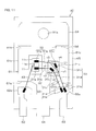
Semiconductor device Download PDFInfo
- Publication number
- EP2765600A1 EP2765600A1 EP12837253.9A EP12837253A EP2765600A1 EP 2765600 A1 EP2765600 A1 EP 2765600A1 EP 12837253 A EP12837253 A EP 12837253A EP 2765600 A1 EP2765600 A1 EP 2765600A1
- Authority
- EP
- European Patent Office
- Prior art keywords
- bonded
- die pad
- pad
- plan
- view
- Prior art date
- Legal status (The legal status is an assumption and is not a legal conclusion. Google has not performed a legal analysis and makes no representation as to the accuracy of the status listed.)
- Pending
Links
Images





Classifications
-
- H—ELECTRICITY
- H10—SEMICONDUCTOR DEVICES; ELECTRIC SOLID-STATE DEVICES NOT OTHERWISE PROVIDED FOR
- H10D—INORGANIC ELECTRIC SEMICONDUCTOR DEVICES
- H10D84/00—Integrated devices formed in or on semiconductor substrates that comprise only semiconducting layers, e.g. on Si wafers or on GaAs-on-Si wafers
- H10D84/80—Integrated devices formed in or on semiconductor substrates that comprise only semiconducting layers, e.g. on Si wafers or on GaAs-on-Si wafers characterised by the integration of at least one component covered by groups H10D12/00 or H10D30/00, e.g. integration of IGFETs
- H10D84/811—Combinations of field-effect devices and one or more diodes, capacitors or resistors
-
- H—ELECTRICITY
- H10—SEMICONDUCTOR DEVICES; ELECTRIC SOLID-STATE DEVICES NOT OTHERWISE PROVIDED FOR
- H10W—GENERIC PACKAGES, INTERCONNECTIONS, CONNECTORS OR OTHER CONSTRUCTIONAL DETAILS OF DEVICES COVERED BY CLASS H10
- H10W70/00—Package substrates; Interposers; Redistribution layers [RDL]
- H10W70/40—Leadframes
- H10W70/464—Additional interconnections in combination with leadframes
- H10W70/465—Bumps or wires
-
- H—ELECTRICITY
- H10—SEMICONDUCTOR DEVICES; ELECTRIC SOLID-STATE DEVICES NOT OTHERWISE PROVIDED FOR
- H10W—GENERIC PACKAGES, INTERCONNECTIONS, CONNECTORS OR OTHER CONSTRUCTIONAL DETAILS OF DEVICES COVERED BY CLASS H10
- H10W70/00—Package substrates; Interposers; Redistribution layers [RDL]
- H10W70/40—Leadframes
- H10W70/481—Leadframes for devices being provided for in groups H10D8/00 - H10D48/00
-
- H—ELECTRICITY
- H10—SEMICONDUCTOR DEVICES; ELECTRIC SOLID-STATE DEVICES NOT OTHERWISE PROVIDED FOR
- H10W—GENERIC PACKAGES, INTERCONNECTIONS, CONNECTORS OR OTHER CONSTRUCTIONAL DETAILS OF DEVICES COVERED BY CLASS H10
- H10W72/00—Interconnections or connectors in packages
- H10W72/90—Bond pads, in general
-
- H—ELECTRICITY
- H10—SEMICONDUCTOR DEVICES; ELECTRIC SOLID-STATE DEVICES NOT OTHERWISE PROVIDED FOR
- H10W—GENERIC PACKAGES, INTERCONNECTIONS, CONNECTORS OR OTHER CONSTRUCTIONAL DETAILS OF DEVICES COVERED BY CLASS H10
- H10W90/00—Package configurations
-
- H—ELECTRICITY
- H10—SEMICONDUCTOR DEVICES; ELECTRIC SOLID-STATE DEVICES NOT OTHERWISE PROVIDED FOR
- H10W—GENERIC PACKAGES, INTERCONNECTIONS, CONNECTORS OR OTHER CONSTRUCTIONAL DETAILS OF DEVICES COVERED BY CLASS H10
- H10W90/00—Package configurations
- H10W90/811—Multiple chips on leadframes
-
- H—ELECTRICITY
- H10—SEMICONDUCTOR DEVICES; ELECTRIC SOLID-STATE DEVICES NOT OTHERWISE PROVIDED FOR
- H10W—GENERIC PACKAGES, INTERCONNECTIONS, CONNECTORS OR OTHER CONSTRUCTIONAL DETAILS OF DEVICES COVERED BY CLASS H10
- H10W72/00—Interconnections or connectors in packages
- H10W72/071—Connecting or disconnecting
- H10W72/0711—Apparatus therefor
- H10W72/07141—Means for applying energy, e.g. ovens or lasers
-
- H—ELECTRICITY
- H10—SEMICONDUCTOR DEVICES; ELECTRIC SOLID-STATE DEVICES NOT OTHERWISE PROVIDED FOR
- H10W—GENERIC PACKAGES, INTERCONNECTIONS, CONNECTORS OR OTHER CONSTRUCTIONAL DETAILS OF DEVICES COVERED BY CLASS H10
- H10W72/00—Interconnections or connectors in packages
- H10W72/071—Connecting or disconnecting
- H10W72/075—Connecting or disconnecting of bond wires
-
- H—ELECTRICITY
- H10—SEMICONDUCTOR DEVICES; ELECTRIC SOLID-STATE DEVICES NOT OTHERWISE PROVIDED FOR
- H10W—GENERIC PACKAGES, INTERCONNECTIONS, CONNECTORS OR OTHER CONSTRUCTIONAL DETAILS OF DEVICES COVERED BY CLASS H10
- H10W72/00—Interconnections or connectors in packages
- H10W72/071—Connecting or disconnecting
- H10W72/075—Connecting or disconnecting of bond wires
- H10W72/07551—Connecting or disconnecting of bond wires characterised by changes in properties of the bond wires during the connecting
- H10W72/07552—Connecting or disconnecting of bond wires characterised by changes in properties of the bond wires during the connecting changes in structures or sizes
-
- H—ELECTRICITY
- H10—SEMICONDUCTOR DEVICES; ELECTRIC SOLID-STATE DEVICES NOT OTHERWISE PROVIDED FOR
- H10W—GENERIC PACKAGES, INTERCONNECTIONS, CONNECTORS OR OTHER CONSTRUCTIONAL DETAILS OF DEVICES COVERED BY CLASS H10
- H10W72/00—Interconnections or connectors in packages
- H10W72/071—Connecting or disconnecting
- H10W72/075—Connecting or disconnecting of bond wires
- H10W72/07551—Connecting or disconnecting of bond wires characterised by changes in properties of the bond wires during the connecting
- H10W72/07553—Connecting or disconnecting of bond wires characterised by changes in properties of the bond wires during the connecting changes in shapes
-
- H—ELECTRICITY
- H10—SEMICONDUCTOR DEVICES; ELECTRIC SOLID-STATE DEVICES NOT OTHERWISE PROVIDED FOR
- H10W—GENERIC PACKAGES, INTERCONNECTIONS, CONNECTORS OR OTHER CONSTRUCTIONAL DETAILS OF DEVICES COVERED BY CLASS H10
- H10W72/00—Interconnections or connectors in packages
- H10W72/071—Connecting or disconnecting
- H10W72/075—Connecting or disconnecting of bond wires
- H10W72/07551—Connecting or disconnecting of bond wires characterised by changes in properties of the bond wires during the connecting
- H10W72/07554—Connecting or disconnecting of bond wires characterised by changes in properties of the bond wires during the connecting changes in dispositions
-
- H—ELECTRICITY
- H10—SEMICONDUCTOR DEVICES; ELECTRIC SOLID-STATE DEVICES NOT OTHERWISE PROVIDED FOR
- H10W—GENERIC PACKAGES, INTERCONNECTIONS, CONNECTORS OR OTHER CONSTRUCTIONAL DETAILS OF DEVICES COVERED BY CLASS H10
- H10W72/00—Interconnections or connectors in packages
- H10W72/30—Die-attach connectors
- H10W72/351—Materials of die-attach connectors
- H10W72/352—Materials of die-attach connectors comprising metals or metalloids, e.g. solders
-
- H—ELECTRICITY
- H10—SEMICONDUCTOR DEVICES; ELECTRIC SOLID-STATE DEVICES NOT OTHERWISE PROVIDED FOR
- H10W—GENERIC PACKAGES, INTERCONNECTIONS, CONNECTORS OR OTHER CONSTRUCTIONAL DETAILS OF DEVICES COVERED BY CLASS H10
- H10W72/00—Interconnections or connectors in packages
- H10W72/50—Bond wires
- H10W72/521—Structures or relative sizes of bond wires
-
- H—ELECTRICITY
- H10—SEMICONDUCTOR DEVICES; ELECTRIC SOLID-STATE DEVICES NOT OTHERWISE PROVIDED FOR
- H10W—GENERIC PACKAGES, INTERCONNECTIONS, CONNECTORS OR OTHER CONSTRUCTIONAL DETAILS OF DEVICES COVERED BY CLASS H10
- H10W72/00—Interconnections or connectors in packages
- H10W72/50—Bond wires
- H10W72/521—Structures or relative sizes of bond wires
- H10W72/527—Multiple bond wires having different sizes
-
- H—ELECTRICITY
- H10—SEMICONDUCTOR DEVICES; ELECTRIC SOLID-STATE DEVICES NOT OTHERWISE PROVIDED FOR
- H10W—GENERIC PACKAGES, INTERCONNECTIONS, CONNECTORS OR OTHER CONSTRUCTIONAL DETAILS OF DEVICES COVERED BY CLASS H10
- H10W72/00—Interconnections or connectors in packages
- H10W72/50—Bond wires
- H10W72/531—Shapes of wire connectors
-
- H—ELECTRICITY
- H10—SEMICONDUCTOR DEVICES; ELECTRIC SOLID-STATE DEVICES NOT OTHERWISE PROVIDED FOR
- H10W—GENERIC PACKAGES, INTERCONNECTIONS, CONNECTORS OR OTHER CONSTRUCTIONAL DETAILS OF DEVICES COVERED BY CLASS H10
- H10W72/00—Interconnections or connectors in packages
- H10W72/50—Bond wires
- H10W72/531—Shapes of wire connectors
- H10W72/536—Shapes of wire connectors the connected ends being ball-shaped
-
- H—ELECTRICITY
- H10—SEMICONDUCTOR DEVICES; ELECTRIC SOLID-STATE DEVICES NOT OTHERWISE PROVIDED FOR
- H10W—GENERIC PACKAGES, INTERCONNECTIONS, CONNECTORS OR OTHER CONSTRUCTIONAL DETAILS OF DEVICES COVERED BY CLASS H10
- H10W72/00—Interconnections or connectors in packages
- H10W72/50—Bond wires
- H10W72/531—Shapes of wire connectors
- H10W72/5363—Shapes of wire connectors the connected ends being wedge-shaped
-
- H—ELECTRICITY
- H10—SEMICONDUCTOR DEVICES; ELECTRIC SOLID-STATE DEVICES NOT OTHERWISE PROVIDED FOR
- H10W—GENERIC PACKAGES, INTERCONNECTIONS, CONNECTORS OR OTHER CONSTRUCTIONAL DETAILS OF DEVICES COVERED BY CLASS H10
- H10W72/00—Interconnections or connectors in packages
- H10W72/50—Bond wires
- H10W72/531—Shapes of wire connectors
- H10W72/5366—Shapes of wire connectors the bond wires having kinks
-
- H—ELECTRICITY
- H10—SEMICONDUCTOR DEVICES; ELECTRIC SOLID-STATE DEVICES NOT OTHERWISE PROVIDED FOR
- H10W—GENERIC PACKAGES, INTERCONNECTIONS, CONNECTORS OR OTHER CONSTRUCTIONAL DETAILS OF DEVICES COVERED BY CLASS H10
- H10W72/00—Interconnections or connectors in packages
- H10W72/50—Bond wires
- H10W72/541—Dispositions of bond wires
- H10W72/5445—Dispositions of bond wires being orthogonal to a side surface of the chip, e.g. parallel arrangements
-
- H—ELECTRICITY
- H10—SEMICONDUCTOR DEVICES; ELECTRIC SOLID-STATE DEVICES NOT OTHERWISE PROVIDED FOR
- H10W—GENERIC PACKAGES, INTERCONNECTIONS, CONNECTORS OR OTHER CONSTRUCTIONAL DETAILS OF DEVICES COVERED BY CLASS H10
- H10W72/00—Interconnections or connectors in packages
- H10W72/50—Bond wires
- H10W72/541—Dispositions of bond wires
- H10W72/547—Dispositions of multiple bond wires
-
- H—ELECTRICITY
- H10—SEMICONDUCTOR DEVICES; ELECTRIC SOLID-STATE DEVICES NOT OTHERWISE PROVIDED FOR
- H10W—GENERIC PACKAGES, INTERCONNECTIONS, CONNECTORS OR OTHER CONSTRUCTIONAL DETAILS OF DEVICES COVERED BY CLASS H10
- H10W72/00—Interconnections or connectors in packages
- H10W72/50—Bond wires
- H10W72/541—Dispositions of bond wires
- H10W72/547—Dispositions of multiple bond wires
- H10W72/5473—Dispositions of multiple bond wires multiple bond wires connected to a common bond pad
-
- H—ELECTRICITY
- H10—SEMICONDUCTOR DEVICES; ELECTRIC SOLID-STATE DEVICES NOT OTHERWISE PROVIDED FOR
- H10W—GENERIC PACKAGES, INTERCONNECTIONS, CONNECTORS OR OTHER CONSTRUCTIONAL DETAILS OF DEVICES COVERED BY CLASS H10
- H10W72/00—Interconnections or connectors in packages
- H10W72/50—Bond wires
- H10W72/541—Dispositions of bond wires
- H10W72/547—Dispositions of multiple bond wires
- H10W72/5475—Dispositions of multiple bond wires multiple bond wires connected to common bond pads at both ends of the wires
-
- H—ELECTRICITY
- H10—SEMICONDUCTOR DEVICES; ELECTRIC SOLID-STATE DEVICES NOT OTHERWISE PROVIDED FOR
- H10W—GENERIC PACKAGES, INTERCONNECTIONS, CONNECTORS OR OTHER CONSTRUCTIONAL DETAILS OF DEVICES COVERED BY CLASS H10
- H10W72/00—Interconnections or connectors in packages
- H10W72/50—Bond wires
- H10W72/551—Materials of bond wires
- H10W72/552—Materials of bond wires comprising metals or metalloids, e.g. silver
- H10W72/5522—Materials of bond wires comprising metals or metalloids, e.g. silver comprising gold [Au]
-
- H—ELECTRICITY
- H10—SEMICONDUCTOR DEVICES; ELECTRIC SOLID-STATE DEVICES NOT OTHERWISE PROVIDED FOR
- H10W—GENERIC PACKAGES, INTERCONNECTIONS, CONNECTORS OR OTHER CONSTRUCTIONAL DETAILS OF DEVICES COVERED BY CLASS H10
- H10W72/00—Interconnections or connectors in packages
- H10W72/50—Bond wires
- H10W72/551—Materials of bond wires
- H10W72/552—Materials of bond wires comprising metals or metalloids, e.g. silver
- H10W72/5524—Materials of bond wires comprising metals or metalloids, e.g. silver comprising aluminium [Al]
-
- H—ELECTRICITY
- H10—SEMICONDUCTOR DEVICES; ELECTRIC SOLID-STATE DEVICES NOT OTHERWISE PROVIDED FOR
- H10W—GENERIC PACKAGES, INTERCONNECTIONS, CONNECTORS OR OTHER CONSTRUCTIONAL DETAILS OF DEVICES COVERED BY CLASS H10
- H10W72/00—Interconnections or connectors in packages
- H10W72/50—Bond wires
- H10W72/59—Bond pads specially adapted therefor
-
- H—ELECTRICITY
- H10—SEMICONDUCTOR DEVICES; ELECTRIC SOLID-STATE DEVICES NOT OTHERWISE PROVIDED FOR
- H10W—GENERIC PACKAGES, INTERCONNECTIONS, CONNECTORS OR OTHER CONSTRUCTIONAL DETAILS OF DEVICES COVERED BY CLASS H10
- H10W72/00—Interconnections or connectors in packages
- H10W72/851—Dispositions of multiple connectors or interconnections
- H10W72/874—On different surfaces
- H10W72/884—Die-attach connectors and bond wires
-
- H—ELECTRICITY
- H10—SEMICONDUCTOR DEVICES; ELECTRIC SOLID-STATE DEVICES NOT OTHERWISE PROVIDED FOR
- H10W—GENERIC PACKAGES, INTERCONNECTIONS, CONNECTORS OR OTHER CONSTRUCTIONAL DETAILS OF DEVICES COVERED BY CLASS H10
- H10W72/00—Interconnections or connectors in packages
- H10W72/90—Bond pads, in general
- H10W72/921—Structures or relative sizes of bond pads
- H10W72/926—Multiple bond pads having different sizes
-
- H—ELECTRICITY
- H10—SEMICONDUCTOR DEVICES; ELECTRIC SOLID-STATE DEVICES NOT OTHERWISE PROVIDED FOR
- H10W—GENERIC PACKAGES, INTERCONNECTIONS, CONNECTORS OR OTHER CONSTRUCTIONAL DETAILS OF DEVICES COVERED BY CLASS H10
- H10W72/00—Interconnections or connectors in packages
- H10W72/90—Bond pads, in general
- H10W72/931—Shapes of bond pads
- H10W72/932—Plan-view shape, i.e. in top view
-
- H—ELECTRICITY
- H10—SEMICONDUCTOR DEVICES; ELECTRIC SOLID-STATE DEVICES NOT OTHERWISE PROVIDED FOR
- H10W—GENERIC PACKAGES, INTERCONNECTIONS, CONNECTORS OR OTHER CONSTRUCTIONAL DETAILS OF DEVICES COVERED BY CLASS H10
- H10W72/00—Interconnections or connectors in packages
- H10W72/90—Bond pads, in general
- H10W72/951—Materials of bond pads
- H10W72/952—Materials of bond pads comprising metals or metalloids, e.g. PbSn, Ag or Cu
-
- H—ELECTRICITY
- H10—SEMICONDUCTOR DEVICES; ELECTRIC SOLID-STATE DEVICES NOT OTHERWISE PROVIDED FOR
- H10W—GENERIC PACKAGES, INTERCONNECTIONS, CONNECTORS OR OTHER CONSTRUCTIONAL DETAILS OF DEVICES COVERED BY CLASS H10
- H10W74/00—Encapsulations, e.g. protective coatings
-
- H—ELECTRICITY
- H10—SEMICONDUCTOR DEVICES; ELECTRIC SOLID-STATE DEVICES NOT OTHERWISE PROVIDED FOR
- H10W—GENERIC PACKAGES, INTERCONNECTIONS, CONNECTORS OR OTHER CONSTRUCTIONAL DETAILS OF DEVICES COVERED BY CLASS H10
- H10W90/00—Package configurations
- H10W90/701—Package configurations characterised by the relative positions of pads or connectors relative to package parts
- H10W90/731—Package configurations characterised by the relative positions of pads or connectors relative to package parts of die-attach connectors
- H10W90/736—Package configurations characterised by the relative positions of pads or connectors relative to package parts of die-attach connectors between a chip and a stacked lead frame, conducting package substrate or heat sink
-
- H—ELECTRICITY
- H10—SEMICONDUCTOR DEVICES; ELECTRIC SOLID-STATE DEVICES NOT OTHERWISE PROVIDED FOR
- H10W—GENERIC PACKAGES, INTERCONNECTIONS, CONNECTORS OR OTHER CONSTRUCTIONAL DETAILS OF DEVICES COVERED BY CLASS H10
- H10W90/00—Package configurations
- H10W90/701—Package configurations characterised by the relative positions of pads or connectors relative to package parts
- H10W90/751—Package configurations characterised by the relative positions of pads or connectors relative to package parts of bond wires
- H10W90/753—Package configurations characterised by the relative positions of pads or connectors relative to package parts of bond wires between laterally-adjacent chips
-
- H—ELECTRICITY
- H10—SEMICONDUCTOR DEVICES; ELECTRIC SOLID-STATE DEVICES NOT OTHERWISE PROVIDED FOR
- H10W—GENERIC PACKAGES, INTERCONNECTIONS, CONNECTORS OR OTHER CONSTRUCTIONAL DETAILS OF DEVICES COVERED BY CLASS H10
- H10W90/00—Package configurations
- H10W90/701—Package configurations characterised by the relative positions of pads or connectors relative to package parts
- H10W90/751—Package configurations characterised by the relative positions of pads or connectors relative to package parts of bond wires
- H10W90/755—Package configurations characterised by the relative positions of pads or connectors relative to package parts of bond wires between a chip and a laterally-adjacent insulating package substrate, interpose or RDL
-
- H—ELECTRICITY
- H10—SEMICONDUCTOR DEVICES; ELECTRIC SOLID-STATE DEVICES NOT OTHERWISE PROVIDED FOR
- H10W—GENERIC PACKAGES, INTERCONNECTIONS, CONNECTORS OR OTHER CONSTRUCTIONAL DETAILS OF DEVICES COVERED BY CLASS H10
- H10W90/00—Package configurations
- H10W90/701—Package configurations characterised by the relative positions of pads or connectors relative to package parts
- H10W90/751—Package configurations characterised by the relative positions of pads or connectors relative to package parts of bond wires
- H10W90/756—Package configurations characterised by the relative positions of pads or connectors relative to package parts of bond wires between a chip and a stacked lead frame, conducting package substrate or heat sink
Definitions
- the present invention relates to a semiconductor device.
- MOSFETs Metal-Oxide-Semiconductor Field Effect Transistors
- MOSFETs include a parasitic PN junction diode (body diode) as a bipolar device.
- body diode parasitic PN junction diode
- MOSFET Metal-Oxide-Semiconductor Field Effect Transistors
- MOSFETs include a parasitic PN junction diode (body diode) as a bipolar device.
- body diode parasitic PN junction diode
- the properties of the device may deteriorate.
- an electron-hole recombination may occur at a crystal fault, if it exists in the MOSFET, to result in an expansion of the crystal fault.
- Basal Plane Dislocation exists in an SiC semiconductor crystal.
- the crystal structure at the BPD is different from those in other portions, that is, the band gap of the crystal is smaller than the inherent band gap of the SiC semiconductor.
- the BPD is therefore likely to be an electron-hole recombination center. Accordingly, when a forward current flows through the PN joint portion, the BPD expands to be a planar fault (stacking fault). This leads to an increase in the on-resistance of the SiC-MOSFET.
- Patent Document 1 Japanese Unexamined Patent Publication No. 2006-310790
- the present invention is directed to a first semiconductor device including a die pad, a bipolar device die-bonded to a surface of the die pad, the bipolar device having a first electrode pad on a surface opposite to a die-bonded surface, a unipolar device die-bonded to the surface of the die pad, the unipolar device having a second electrode pad to be connected electrically to the fist electrode pad on a surface opposite to a die-bonded surface, a conductive member disposed laterally to the die pad to be connected electrically with the second electrode pad, and a bonding wire, one end of which is bonded to the first electrode pad, the other end of which is bonded to the conductive member, and the center of which is bonded to the second electrode pad.
- a first wire portion of the bonding wire between the portion bonded to the first electrode pad and the portion bonded to the second electrode pad is at an angle of 90 degrees or more, in a plan view, with respect to a second wire portion of the bonding wire between the portion bonded to the second electrode pad and the portion bonded to the conductive member.
- connection between the portion of the bonding wire bonded to the second electrode pad and the first wire portion as well as the connection between the portion of the bonding wire bonded to the second electrode pad and the second wire portion are likely to be under load.
- the angle between the first wire portion and the second wire portion is 90 degrees or more in a plan view, which cannot cause unnecessary load and therefore strength reduction, whereby it is possible for the connections to have increased strength.
- the die pad has a quadrangular shape in a plan view.
- the conductive member is disposed in a manner opposed to a portion near one end of a predetermined first side of the die pad in a plan view.
- One of the four sides of the die pad extending perpendicular to the first side from the one end of the first side near which the conductive member is disposed being defined as a second side in a plan view, the unipolar device is disposed at a position closer to the second side and the first side of the die pad than the bipolar device. In accordance with this arrangement, it is possible to increase the angle between the first wire portion and the second wire portion.
- the unipolar device being disposed at a position closer to the second side and the first side of the die pad than the bipolar device means that the center of gravity of the unipolar device is disposed at a position closer to the second side and the first side of the die pad than the center of gravity of the bipolar device.
- the bipolar device has a quadrangular shape in a plan view.
- the bipolar device is die-bonded to the die pad at a posture rotated, from a posture in which the four sides of the bipolar device are parallel, respectively, with the four sides of the die pad in a plan view, by a required angle with respect to the die pad such that the corresponding opposed sides of the bipolar device and the die pad are not parallel with each other.
- the length direction of one of the four sides of the bipolar device inclined with respect to the first side of the die pad in a manner coming close to the first side so as to come close to the second side of the die pad is parallel, in a plan view, with the length direction of the portion of the bonding wire bonded to the first electrode pad.
- the bipolar device has a rectangular shape in a plan view.
- the long sides of the bipolar device are inclined with respect to the first side of the die pad and extend toward the intersection between the first side and the second side of the die pad. In accordance with this arrangement, it is possible to further increase the bonding area between the bonding wire and the first electrode pad.
- the unipolar device has a quadrangular shape in a plan view.
- the unipolar device is die-bonded to the die pad at a posture rotated, from a posture in which the four sides of the unipolar device are parallel, respectively, with the four sides of the die pad in a plan view, by a required angle with respect to the die pad such that the corresponding opposed sides of the unipolar device and the die pad are not parallel with each other.
- the length direction of one of the four sides of the unipolar device inclined with respect to the first side of the die pad in a manner coming close to the first side so as to come close to the second side of the die pad is parallel, in a plan view, with the length direction of the portion of the bonding wire bonded to the second electrode pad.
- the unipolar device has a rectangular shape in a plan view.
- the long sides of the unipolar device are inclined with respect to the first side of the die pad and extend toward the intersection between the first side and the second side of the die pad. In accordance with this arrangement, it is possible to further increase the bonding area between the bonding wire and the second electrode pad.
- the surface opposite to the die-bonded surface of the bipolar device is provided with a third electrode pad at a position different from that of the first electrode pad, the third electrode pad corresponding to a gate electrode if the bipolar device is a MOS transistor, to a gate electrode if the bipolar device is an IGBT, or to a base electrode if the bipolar device is a bipolar transistor.
- the third electrode pad is disposed at one of the corners on the surface of the bipolar device farther from the second side but closer to the first side of the die pad.
- the die pad has a quadrangular shape in a plan view.
- the conductive member is disposed in a manner opposed to a portion near one end of a predetermined first side of the die pad in a plan view.
- One of the four sides of the die pad extending perpendicular to the first side from the one end of the first side near which the conductive member is disposed being defined as a second side in a plan view, the bipolar device and the unipolar device are disposed side by side in the direction parallel with the second side and the unipolar device is disposed closer to the first side than the bipolar device.
- the bipolar device has a quadrangular shape in a plan view.
- the bipolar device is die-bonded to the die pad at a posture in which the four sides of the bipolar device are parallel, respectively, with the four sides of the die pad in a plan view.
- the length direction of one of the four sides of the bipolar device parallel with the second side of the die pad is parallel, in a plan view, with the length direction of the portion of the bonding wire bonded to the first electrode pad.
- the unipolar device has a quadrangular shape in a plan view.
- the unipolar device is die-bonded to the die pad at a posture in which the four sides of the unipolar device are parallel, respectively, with the four sides of the die pad in a plan view.
- the length direction of one of the four sides of the unipolar device parallel with the second side of the die pad is parallel, in a plan view, with the length direction of the portion of the bonding wire bonded to the second electrode pad.
- the surface opposite to the die-bonded surface of the bipolar device is provided with a third electrode pad at a position different from that of the first electrode pad, the third electrode pad corresponding to a gate electrode if the bipolar device is a MOS transistor, to a gate electrode if the bipolar device is an IGBT, or to a base electrode if the bipolar device is a bipolar transistor.
- the third electrode pad is disposed at one of the corners on the surface of the bipolar device farther from the second side but closer to the first side of the die pad.
- the first wire portion is shorter than the second wire portion.
- the angle between the portion of the bonding wire bonded to the second electrode pad and the first wire portion is greater, in a plan view, than the angle between the portion of the bonding wire bonded to the second electrode pad and the second wire portion.
- the first wire portion is shorter than the second wire portion, the first wire portion is less likely to absorb an external force such as a pulling force, if applied thereto, than the second wire portion.
- the angle between the portion of the bonding wire bonded to the second electrode pad and the first wire portion is made greater than the angle between the portion of the bonding wire bonded to the second electrode pad and the second wire portion, so that the strength of the connection between the portion of the bonding wire bonded to the second electrode pad and the first wire portion is higher than the strength of the connection between the portion of the bonding wire bonded to the second electrode pad and the second wire portion.
- multiple sets of the bipolar device and the unipolar device are disposed on the surface of the die pad in a spaced manner in the direction parallel with the second side of the die pad and connected in parallel to each other.
- another bipolar device having a fourth electrode pad and another unipolar device having a fifth electrode pad are disposed side by side between the bipolar device and the unipolar device on the surface of the die pad, and the center of the first wire portion is bonded to the fourth electrode pad and the fifth electrode pad.
- the die pad has a quadrangular shape in a plan view, in which the conductive member is disposed in a manner opposed to a portion near one end of a predetermined first side of the die pad in a plan view, and in which one of the four sides of the die pad extending perpendicular to the first side from the one end of the first side near which the conductive member is disposed being defined as a second side in a plan view, the unipolar device is disposed at a position closer to the second side of the die pad than the bipolar device.
- Multiple bonding wires are provided and disposed in a spaced manner in a plan view, in which the angle between the first wire portion and the second wire portion is greater at the position of each bonding wire farther from the first side of the die pad.
- the multiple bonding wires are two bonding wires, in which the bipolar device has a rectangular shape in a plan view and the first electrode pad has a rectangular shape in a plan view, and the bipolar device is die-bonded to the die pad at a posture in which the long sides of the bipolar device are parallel with the second side of the die pad.
- the first bonded portion of one of the two bonding wires positioned farther from the first side of the die pad is bonded to one of two regions defined by bisecting the surface of the first electrode pad along the second side of the die pad, the one region being farther from the first side.
- the first bonded portion of the other of the two bonding wires positioned closer to the first side of the die pad is bonded to the other of the two regions defined by bisecting the surface of the first electrode pad along the second side of the die pad, the other region being closer to the first side.
- the unipolar device has a square shape in a plan view and the second electrode pad has a square shape in a plan view, in which the unipolar device is die-bonded to the die pad at a posture in which the four sides of the unipolar device are parallel, respectively, with the four sides of the die pad.
- One of the four vertices of the second electrode pad closer to the first side and the second side of the die pad being defined as a first vertex
- one of the four vertices closer to the first side but farther from the second side of the die pad being defined as a second vertex
- the vertex diagonal to the first vertex being defined as a third vertex
- the vertex diagonal to the second vertex being defined as a fourth vertex
- the second bonded portion of one of the two bonding wires positioned farther from the first side of the die pad is bonded to one of two regions defined by bisecting the surface of the second electrode with the diagonal line running between the first vertex and the third vertex, the one region being closer to the fourth vertex.
- the second bonded portion of the other of the two bonding wires positioned closer to the first side of the die pad is bonded to the other of the two regions defined by bisecting the surface of the second electrode pad with the diagonal line, the other region being closer to the second vertex.
- the center of gravity of the unipolar device is disposed at a position closer to the first side of the die pad than the center of gravity of the bipolar device in a plan view.
- the bipolar device includes a PN junction diode structure and the unipolar device includes a Schottky barrier diode.
- the present invention is directed to a second semiconductor device including two first semiconductor devices, in which the first electrode pad in one of the first semiconductor devices is connected to the die pad in the other of the first semiconductor devices through a connective metal member.
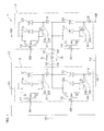
- FIG. 1 is an electrical circuit diagram of an inverter circuit 1 to which a semiconductor device according to a preferred embodiment of the present invention is applied.
- the inverter circuit 1 includes a first module 2 and a second module 3.
- the first module 2 includes a first power supply terminal 51, a second power supply terminal 53, two gate terminals 54 and 55, and an output terminal 52.
- the second module 3 includes a first power supply terminal 56, a second power supply terminal 58, two gate terminals 59 and 60, and an output terminal 57.
- the first power supply terminals 51 and 56 of the respective modules 2 and 3 are connected to the positive terminal of a power supply 15 (DC power supply) via a first output line 17.
- An inductive load 16 is connected between the output terminals 52 and 57 of the respective modules 2 and 3 via a second output line 18.
- the second power supply terminals 53 and 58 of the respective modules 2 and 3 are connected to the negative terminal of the power supply 15 via a third output line 19.
- a control unit not shown is connected to the gate terminals 54, 55, 59, and 60 of the respective modules 2 and 3.
- the first module 2 includes a high-side first MOSFET 11 and a low-side second MOSFET 12 connected in series to the first MOSFET 11.
- the MOSFETs 11 and 12 incorporate a first PN junction diode (body diode) 11a and a second PN junction diode 12a, respectively.
- the PN junction diodes 11a and 12a are bipolar devices.
- the anodes and cathodes of the PN junction diodes 11a and 12a are connected electrically to the sources and drains of the corresponding MOSFETs 11 and 12, respectively.
- a first Schottky barrier diode 21 and a second Schottky barrier diode 22 serving as unipolar devices are connected in parallel to the respective MOSFETs 11 and 12. That is, the Schottky barrier diodes 21 and 22 serving as unipolar devices are connected in parallel to the PN junction diodes 11a and 12a serving as bipolar devices.
- the drain of the first MOSFET 11 is connected to the first power supply terminal 51 of the first module 2.
- the cathode of the first Schottky barrier diode 21 is connected to the drain of the first MOSFET 11 (the cathode of the first PN junction diode 11a).
- the source of the first MOSFET 11 (the anode of the first PN junction diode 11a) is connected to the anode of the first Schottky barrier diode 21 via a connective metal member 32.
- the anode of the first Schottky barrier diode 21 is connected to the output terminal 52 of the first module 2 via a connective metal member 33.
- the connective metal members 32 and 33 include parasitic inductances L1 and L2, respectively.
- the connective metal members 32 and 33 are composed of a single bonding wire 31 as will hereinafter be described.
- the drain of the second MOSFET 12 is connected to the output terminal 52 of the first module 2.
- the cathode of the second Schottky barrier diode 22 is connected to the drain of the second MOSFET 12 (the cathode of the second PN junction diode 12a).
- the source of the second MOSFET 12 (the anode of the second PN junction diode 12a) is connected to the anode of the second Schottky barrier diode 22 via a connective metal member 35.
- the anode of the second Schottky barrier diode 22 is connected to the second power supply terminal 53 of the first module 2 via a connective metal member 36.
- the connective metal members 35 and 36 include parasitic inductances L3 and L4, respectively.
- the connective metal members 35 and 36 are composed of a single bonding wire 34.
- the secondmodule 3 includes a high-side thirdMOSFET 13 and a low-side fourth MOSFET 14 connected in series to the third MOSFET 13.
- the MOSFETs 13 and 14 incorporate third and fourthPNjunctiondiodes (body diodes) 13a and 14a, respectively.
- the PN junction diodes 13a and 14a are bipolar devices.
- the anodes and cathodes of the PN junction diodes 13a and 14a are connected electrically to the sources and drains of the corresponding MOSFETs 13 and 14, respectively.
- Third and fourth Schottky barrier diodes 23 and 24 are connected in parallel to the respective MOSFETs 13 and 14. That is, the Schottky barrier diodes 23 and 24 serving as unipolar devices are connected in parallel to the PN junction diodes 13a and 14a serving as bipolar devices.
- the drain of the third MOSFET 13 is connected to the first power supply terminal 56 of the second module 3.
- the cathode of the third Schottky barrier diode 23 is connected to the drain of the third MOSFET 13 (the cathode of the third PN junction diode 13a).
- the source of the third MOSFET 13 (the anode of the third PN junction diode 13a) is connected to the anode of the third Schottky barrier diode 23 via a connective metal member 38.
- the anode of the third Schottky barrier diode 23 is connected to the output terminal 57 of the second module 3 via a connective metalmember 39.
- the connective metal members 38 and 39 include parasitic inductances L5 and L6, respectively.
- the connective metal members 38 and 39 are composed of a single bonding wire 37.
- the drain of the fourth MOSFET 14 is connected to the output terminal 57 of the second module 3.
- the cathode of the fourth Schottky barrier diode 24 is connected to the drain of the fourth MOSFET 14 (the cathode of the fourth PN junction diode 14a).
- the source of the fourth MOSFET 14 (the anode of the fourth PN junction diode 14a) is connected to the anode of the fourth Schottky barrier diode 24 via a connective metal member 41.
- the anode of the fourth Schottky barrier diode 24 is connected to the second power supply terminal 58 of the second module 3 via a connective metal member 42.
- the connective metal members 41 and 42 include parasitic inductances L7 and L8, respectively.
- the connective metal members 41 and 42 are composed of a single bonding wire 40.
- the first to fourth MOSFETs 11 to 14 are SiC devices prepared using a semiconductor material such as SiC (silicon carbide), an example of composite semiconductor.
- the forward turn-on voltage Vf1 of the Schottky barrier diodes 21 to 24 is lower than the forward turn-on voltage Vf2 of the PN junction diodes 11a to 14a.
- the forward turn-on voltage Vf2 of the PN junction diodes 11a to 14a is, for example, 2.0 V.
- the forward turn-on voltage Vf1 of the Schottky barrier diodes 21 to 24 is, for example, 1.0 V.
- the first MOSFET 11 and the fourth MOSFET 14 are turned on, for example. Thereafter, the MOSFETs 11 and 14 are turned off, so that all of the MOSFETs 11 to 14 are put in an off-state. After a predetermined dead time, the second MOSFET 12 and the third MOSFET 13 are subsequently turned on. Thereafter, the MOSFETs 12 and 13 are turned off, so that all of the MOSFETs 11 to 14 are put in an off-state. After a predetermined dead time, the first MOSFET 11 and the fourth MOSFET 14 are turned on again. Such a repetitive operation drives the load 16 alternately.
- the inductance of the inductive load 16 acts to maintain the current flowing through the load 16 (flowing in the direction indicated by the arrow A).
- This causes a current to flow from the connective metal member 36 to the third Schottky barrier diode 23 through the connective metal member 36, the second Schottky barrier diode 22, the load 16, the connective metal member 39, and the third Schottky barrier diode 23.
- the current thus flows through the connective metal member 36 and the connective metal member 39.
- the parasitic inductance L4 When the current thus flows through the connective metal member 36, the parasitic inductance L4 generates a back electromotive force.
- the anode of the second PN junction diode 12a is connected to the anode of the second Schottky barrier diode 22 through the connective metal member 35, the voltage applied to the second PN junction diode 12a can only be as high as the forward turn-on voltage Vf1 of the second Schottky barrier diode 22. That is, the voltage applied to the second PN junction diode 12a cannot be equal to or higher than the forward turn-on voltage Vf2 thereof. No current can thus flow through the second PN junction diode 12a.
- the parasitic inductance L6 when the current thus flows through the connective metal member 39, the parasitic inductance L6 generates a back electromotive force.
- the anode of the third PN junction diode 13a is connected to the anode of the third Schottky barrier diode 23 through the connective metal member 38, the voltage applied to the third PN junction diode 13a can only be as high as the forward turn-on voltage Vf1 of the third Schottky barrier diode 23. That is, the voltage applied to the third PN junction diode 13a cannot be equal to or higher than the forward turn-on voltage Vf2 thereof. No current can thus flow through the third PN junction diode 13a.
- the inductance of the inductive load 16 acts to maintain the current flowing through the load 16 (flowing in the direction indicated by the arrow B).
- This causes a current to flow from the connective metal member 42 to the first Schottky barrier diode 21 through the connective metal member 42, the fourth Schottky barrier diode 24, the load 16, the connective metal member 33, and the first Schottky barrier diode 21.
- the current thus flows through the connective metal member 42 and the connective metal member 33.
- the parasitic inductance L8 When the current thus flows through the connective metal member 42, the parasitic inductance L8 generates a back electromotive force.
- the anode of the fourth PN junction diode 14a is connected to the anode of the fourth Schottky barrier diode 24 through the connective metal member 41, the voltage applied to the fourth PN junction diode 14a can only be as high as the forward turn-on voltage Vf1 of the fourth Schottky barrier diode 24. That is, the voltage applied to the fourth PN junction diode 14a cannot be equal to or higher than the forward turn-on voltage Vf2 thereof. No current can thus flow through the fourth PN junction diode 14a.
- the parasitic inductance L2 when the current thus flows through the connective metal member 33, the parasitic inductance L2 generates a back electromotive force.
- the anode of the first PN junction diode 11a is connected to the anode of the first Schottky barrier diode 21 through the connective metal member 32, the voltage applied to the first PN junction diode 11a can only be as high as the forward turn-on voltage Vf1 of the first Schottky barrier diode 21. That is, the voltage applied to the first PN junction diode 11a cannot be equal to or higher than the forward turn-on voltage Vf2 thereof. No current can thus flow through the first PN junction diode 11a.
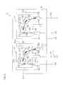
- FIG. 2 is a schematic plan view showing the internal structure of the module 2 shown in FIG. 1 .
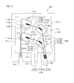
- FIG. 3 is an enlarged plan view of the package 4 shown in FIG. 2 .
- FIG. 4 is a partially enlarged plan view of FIG. 3 .
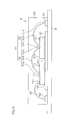
- FIG. 5 is a schematic side view showing the internal structure of the package 4 shown in FIG. 2 .
- the module 2 includes an insulating substrate 8, two packages 4 and 5 fixed on the insulating substrate 8, and a case (not shown) fixed on a surface of the insulating substrate 8 to house the two packages 4 and 5 therein.
- the insulating substrate 8 is formed in a rectangular shape in a plan view elongated laterally in FIG. 2 .
- the packages 4 and 5 are each formed in a rectangular shape in a plan view elongated laterally in FIG. 2 .
- the two packages 4 and 5 are disposed side by side in the longitudinal direction of the insulating substrate 8.
- front represents the lower side in FIG. 3
- rear represents the upper side in FIG. 3
- left represents the left side in FIG. 3
- right represents the right side in FIG. 3 .
- the package 4 includes a die pad 61, a gate lead 62, a source lead (conductive member) 63, the first MOSFET 11, the first Schottky barrier diode 21, and a molding resin 65 encapsulating these components therein.
- the die pad 61 has an approximately rectangular shape elongated laterally in a plan view, having a pair of long sides 61a and 61b and a pair of short sides 61c and 61d.
- the first MOSFET 11 and the first Schottky barrier diode 21 each have a rectangular shape in a plan view.
- the die pad 61 has a lead portion (hereinafter referred to as "drain lead 64") protruding forward from approximately the center of the front long side (first side) 61a.
- the leading end of the drain lead 64 protrudes out of the molding resin 65.
- the gate lead 62 and the source lead 63 are disposed on either side of and parallel with the drain lead 64.
- the gate lead 62 is disposed in a manner opposed to a portion near the left end of the front long side 61a of the die pad 61
- the source lead 63 is disposed in a manner opposed to a portion near the right end of the front long side 61a of the die pad 61.
- One end of the gate lead 62 and the source lead 63 protrudes out of the molding resin 65.
- the die pad 61, the gate lead 62, and the source lead 63 are each composed of, for example, a copper or aluminum plate-like body.
- the first MOSFET 11 and the first Schottky barrier diode 21 are disposed in such a manner that the first Schottky barrier diode 21 is positioned obliquely forward to the right from the first MOSFET 11 in a plan view. That is, the first Schottky barrier diode 21 is disposed at a position closer to the right short side (second side) 61d and the front long side 61a of the die pad 61 than the first MOSFET 11.
- the first MOSFET 11 is disposed at a posture rotated, from a posture in which the four sides of the first MOSFET 11 are parallel, respectively, with the four sides 61a to 61d of the die pad 61 in a plan view, by a first required angle with respect to the die pad 61 such that the corresponding opposed sides of the first MOSFET 11 and the die pad 61 are not parallel with each other.
- the long sides of the first MOSFET 11 are inclined, in a plan view, with respect to the long sides 61a and 61b of the die pad 61 in a manner coming close to the front long side 61a of the die pad 61 so as to come close to the right short side 61d of the die pad 61.
- the long sides of the first MOSFET 11 also extend toward the intersection between the right short side 61d and the front long side 61a of the die pad 61.
- the first Schottky barrier diode 21 is disposed at a posture rotated, from a posture in which the four sides of the first Schottky barrier diode 21 are parallel, respectively, with the four sides 61a to 61d of the die pad 61 in a plan view, by a second required angle with respect to the die pad 61 such that the corresponding opposed sides of the first Schottky barrier diode 21 and the die pad 61 are not parallel with each other.
- the long sides of the first Schottky barrier diode 21 are inclined, in a plan view, with respect to the long sides 61a and 61b of the die pad 61 in a manner coming close to the front long side 61a of the die pad 61 so as to come close to the right short side 61d of the die pad 61.
- the long sides of the first Schottky barrier diode 21 also extend toward the intersection between the right short side 61d and the front long side 61a of the die pad 61.
- the angle of inclination of the long sides of the first Schottky barrier diode 21 with respect to the long sides 61a and 61b of the die pad 61 is greater than the angle of inclination of the long sides of the first MOSFET 11 with respect to the long sides 61a and 61b of the die pad 61.
- the first MOSFET 11 and the first Schottky barrier diode 21 are die-bonded to the surface of the die pad 61.
- the first MOSFET 11 has a drain electrode (drain pad) 11 D on a surface opposed to the die pad 61, the drain electrode 11 D being bonded to the die pad 61 with conductive brazing metal.
- the first MOSFET 11 also has a source electrode (source pad) 11 S and a gate electrode (gate pad) 11 G on the surface opposite to the surface die-bonded to the die pad 61.
- the source electrode 11 S has an approximately rectangular shape in a plan view and is formed to cover almost all of the surface of the first MOSFET 11.
- the length of the long sides of the source electrode 11 S is, for example, about 1.7 mm, while the length of the short sides of the source electrode 11 S is, for example, about 1.5 mm.
- the front left corner of the source electrode 11 S is removed to form a region having an approximately square shape in a plan view. In the removed region, the source electrode 11 S is not formed.
- the gate electrode 11 G is disposed in the removed region.
- the gate electrode 11 G is disposed at one of the four corners on the surface of the first MOSFET 11 farthest from the right short side 61d of the die pad 61.
- the gate electrode 11 G is thus disposed at the corner farther from the right short side 61d of the die pad 61 but closer to the front long side 61a of the die pad 61.
- the gate electrode 11 G has an approximately square shape in a plan view and the length of each side is, for example, about 600 ⁇ m.
- the first Schottky barrier diode 21 has a cathode electrode (cathode pad) 21 K on a surface opposed to the die pad 61, the cathode electrode 21 K being bonded to the die pad 61 with conductive brazing metal.
- the first Schottky barrier diode 21 also has an anode electrode (anode pad) 21 A on the surface opposite to the surface die-bonded to the die pad 61.
- the anode electrode 21 A has an approximately rectangular shape in a plan view and is formed to cover almost all of the surface of the first Schottky barrier diode 21. In a plan view, the length of the long sides of the anode electrode 21 A is about 1. 5 mm, while the length of the short sides of the anode electrode 21 A is about 1.4 mm.
- the gate electrode 11 G of the first MOSFET 11 is connected electrically to the gate lead 62 through a bonding wire 43.
- the connection is achieved by, for example, ball bonding using an Au wire with a diameter of about 25 to 75 ⁇ m or wedge bonding using an Al wire with a diameter of about 50 to 150 ⁇ m.
- the source electrode 11 S of the first MOSFET 11, the anode electrode 21 A of the first Schottky barrier diode 21, and the source lead 63 are bonded electrically to each other via a bonding wire 31, one end of which is bonded to the source electrode 11 S of the first MOSFET 11, the other end of which is bonded to the source lead 63, and the center of which is bonded to the anode electrode 21 A of the first Schottky barrier diode 21.
- the connections are achieved by wedge bonding.
- connections are achieved by stitch bonding starting from one of the source electrode 11 S of the first MOSFET 11 and the source lead 63 through the anode electrode 21 A of the first Schottky barrier diode 21 to end at the other of the source electrode 11 S of the first MOSFET 11 and the source lead 63.
- first bonded portion 31a The portion of the bonding wire 31 bonded to the source electrode 11 S of the first MOSFET 11 will hereinafter be referred to as first bonded portion 31a
- second bonded portion 31c the portion bonded to the anode electrode 21 A of the first Schottky barrier diode 21
- third bonded portion 31e the portion bonded to the source lead 63
- first wire portion 31b the portion of the bonding wire 31 between the first bonded portion 31a and the second bonded portion 31c
- second wire portion 31d the portion between the second bonded portion 31c and the third bonded portion 31e
- the source electrode 11 S of the first MOSFET 11 and the anode electrode 21 A of the first Schottky barrier diode 21 are connected electrically to each other through the portion (connective metal member) 32 of the entire length of the bonding wire 31, including the first bonded portion 31a, the first wire portion 31b, and the second bonded portion 31c.
- the anode electrode 21 A of the first Schottky barrier diode 21 and the source lead 63 are connected electrically to each other through the portion (connective metal member) 33 of the entire length of the bonding wire 31, including the second bonded portion 31c, the second wire portion 31d, and the third bonded portion 31e.
- the bonding wire 31 is, for example, an Al wire with a diameter of about 250 to 400 ⁇ m.
- the bonded portions 31a, 31c, and 31e each have an approximately rectangular shape in a plan view elongated in the length direction of the bonding wire 31 and have a longitudinal length about four times the diameter of the bonding wire 31 (about 1 to 1. 6 mm), while having a width length about two times the diameter of the bonding wire 31 (about 0.5 to 0.8 mm). Accordingly, the size of the bonded portion 31a relative to the source electrode 11 S of the first MOSFET 11 and the size of the second bonded portion 31c relative to the anode electrode 21 A of the first Schottky barrier diode 21 are actually larger than those shown in FIG. 3 .
- the first bonded portion 31a of the bonding wire 31 is bonded to the source electrode 11 S of the first MOSFET 11 in a state where the longitudinal direction of the first bonded portion 31a is parallel, in a plan view, with the long sides of the first MOSFET 11 (the long sides of the source electrode 11 S ). It is therefore possible to increase the bonding area between the bonding wire 31 and the source electrode 11 S and therefore the bonding strength between the bonding wire 31 and the source electrode 11 S can be increased.
- the flattened portion of the bonding wire 31 is bonded to the source electrode 11 S in a state where the longitudinal direction of the flattened portion is parallel with the long sides of the first MOSFET 11, which can prevent or reduce such partial run-off of the flattened portion from the surface of the source electrode 11 S . It is therefore possible to increase the bonding area between the bonding wire 31 and the source electrode 11 S .
- the second bonded portion 31c of the bonding wire 31 is bonded to the anode electrode 21 A of the first Schottky barrier diode 21 in a state where the longitudinal direction of the second bonded portion 31c is parallel with the long sides of the Schottky barrier diode 21 (the long sides of the anode electrode 21 A ). It is therefore possible to increase the bonding area between the bonding wire 31 and the anode electrode 21 A and therefore the bonding strength between the bonding wire 31 and the anode electrode 21 A can be increased.
- the source lead 63 is disposed in a manner opposed to a portion near the right end of the front long side 61a of the die pad 61.
- the first Schottky barrier diode 21 is disposed at a position closer to the right short side 61d and the front long side 61a of the die pad 61 than the first MOSFET 11.
- the angle ⁇ 1 (the narrower; the same applies hereinafter) between the first wire portion 31b and the second wire portion 31d to be great in a plan view, as shown in FIG. 4 .
- the angle ⁇ 1 can be 90 degrees or more.
- the angle ⁇ 2 between the first wire portion 31b and the second bonded portion 31c and the angle ⁇ 3 between the second wire portion 31d and the second bonded portion 31c are each also 90 degrees or more in a plan view.
- connection between the first wire portion 31b and the second bonded portion 31c as well as the connection between the second wire portion 31d and the second bonded portion 31c are likely to be under load, but the angles ⁇ 1, ⁇ 2, and ⁇ 3 are 90 degrees or more, whereby it is possible for the connections to have increased strength.
- the first wire portion 31b is shorter than the second wire portion 31d and the angle ⁇ 2 is greater than the angle ⁇ 3. Since the first wire portion 31b is shorter than the second wire portion 31d, the first wire portion 31b is less likely to absorb an external force such as a pulling force, if applied thereto, than the second wire portion 31d. Hence, the angle ⁇ 2 is made greater than the angle ⁇ 3, so that the strength of the connection between the first wire portion 31b and the second bonded portion 31c is higher than the strength of the connection between the second wire portion 31d and the second bonded portion 31c.
- the package 5 includes a die pad 66 having a lead portion (drain lead 69), a gate lead 67, a source lead 68, the second MOSFET 12, the second Schottky barrier diode 22, and a molding resin 70 encapsulating these components therein.
- the internal structure of the package 5, which is the same as the internal structure of the package 4, will not be described in detail.
- the sign 45 denotes a bonding wire for electrically connecting the gate electrode 12 G of the second MOSFET 12 to the gate lead 67, corresponding to the bonding wire 43 in the package 4.
- the sign 34 denotes a bonding wire for electrically connecting the source electrode 12 S of the second MOSFET 12, the anode electrode 22 A of the second Schottky barrier diode 22, and the source lead 68, corresponding to the bonding wire 31 in the package 4.
- the source lead 63 of the package 4 and the drain lead 69 of the package 5 are connected electrically to each other through a strip-like metal pattern 71 having a U shape in a plan view.
- the metal pattern 71 is composed of, for example, copper or aluminum thin film wiring and formed on the surface of the insulating substrate 8.
- the gate lead 62 of the package 4 is connected to a gate terminal 54.
- the gate terminal 54 is on the outside of the case of the module 2.
- the drain lead 64 of the package 4 is connected to the first power supply terminal 51.
- the first power supply terminal 51 is on the outside of the case of the module 2.
- the first power supply terminal 51 is connected with the power supply 15.
- the metal pattern 71 is connected to the output terminal 52.
- the output terminal 52 is on the outside of the case of the module 2.
- the gate lead 67 of the package 5 is connected to a gate terminal 55.
- the gate terminal 55 is on the outside of the case of the module 2.
- the source lead 68 of the package 5 is connected to the second power supply terminal 53.
- the second power supply terminal 53 is on the outside of the case of the module 2.
- the second power supply terminal 53 is grounded (connected to the negative terminal of the power supply 15).
- FIG. 6 is a schematic plan view showing a first exemplary variation of the package 4.
- components corresponding to those in FIG. 3 are designated by the same signs in FIG. 3 .
- front represents the lower side in FIG. 6
- rear represents the upper side in FIG. 6
- left represents the left side in FIG. 6
- right represents the right side in FIG. 6 .
- the first MOSFET 11 and the first Schottky barrier diode 21 are disposed differently from the package 4 shown in FIG. 3 .
- the first MOSFET 11 and the first Schottky barrier diode 21 are disposed side by side in the anteroposterior direction in the width center of the die pad 61 in a plan view.
- Schottky barrier diode 21 is disposed in front of the first MOSFET 11.
- the first MOSFET 11 has a rectangular shape in a plan view and is disposed such that the long sides thereof are parallel with the right short side 61d of the die pad 61.
- the first Schottky barrier diode 21 has a rectangular shape in a plan view and is disposed such that the long sides thereof are parallel with the right short side 61d of the die pad 61.
- the gate electrode (gate pad) 11 G of the first MOSFET 11 is disposed at the front left corner on the surface of the first MOSFET 11. That is, the gate electrode 11 G is disposed at one of the four corners on the surface of the first MOSFET 11 farther from the right short side 61d but closer to the front long side 61a of the die pad 61.
- the gate electrode 11 G of the first MOSFET 11 is connected electrically to the gate lead 62 through the bonding wire 43.
- the source electrode 11 S of the first MOSFET 11, the anode electrode 21 A of the first Schottky barrier diode 21, and the source lead 63 are bonded electrically to each other through the bonding wire 31, one end of which is bonded to the source electrode 11 S of the first MOSFET 11, the other end of which is bonded to the source lead 63, and the center of which is bonded to the anode electrode 21 A of the first Schottky barrier diode 21.
- the connections are achieved by stitch bonding.
- first bonded portion 31a The portion of the bonding wire 31 bonded to the source electrode 11 S of the first MOSFET 11 will hereinafter be referred to as first bonded portion 31a
- second bonded portion 31c the portion bonded to the anode electrode 21 A of the first Schottky barrier diode 21
- third bonded portion 31e the portion bonded to the source lead 63
- first wire portion 31b the portion of the bonding wire 31 between the first bonded portion 31a and the second bonded portion 31c
- second wire portion 31d the portion between the second bonded portion 31c and the third bonded portion 31e
- the source electrode 11 S of the first MOSFET 11 and the anode electrode 21 A of the first Schottky barrier diode 21 are connected electrically to each other through the portion (connective metal member) 32 of the entire length of the bonding wire 31, including the first bonded portion 31a, the first wire portion 31b, and the second bonded portion 31c.
- the anode electrode 21 A of the first Schottky barrier diode 21 and the source lead 63 are connected electrically to each other through the portion (connective metal member) 33 of the entire length of the bonding wire 31, including the second bonded portion 31c, the second wire portion 31d, and the third bonded portion 31e.
- the first bonded portion 31a of the bonding wire 31 is bonded to the source electrode 11 S of the first MOSFET 11 in a state where the longitudinal direction of the first bonded portion 31a is parallel, in a plan view, with the long sides of the first MOSFET 11 (the long sides of the source electrode 11 S ). It is therefore possible to increase the bonding area between the bonding wire 31 and the source electrode 11 S and therefore the bonding strength between the bonding wire 31 and the source electrode 11 S can be increased.
- the second bonded portion 31c of the bonding wire 31 is bonded to the anode electrode 21 A of the first Schottky barrier diode 21 in a state where the longitudinal direction of the second bonded portion 31c is parallel with the long sides of the Schottky barrier diode 21 (the long sides of the anode electrode 21 A ). It is therefore possible to increase the bonding area between the bonding wire 31 and the anode electrode 21 A and therefore the bonding strength between the bonding wire 31 and the anode electrode 21 A can be increased.
- the angle between the first wire portion 31b and the second wire portion 31d is 90 degrees or more in a plan view.
- the angle between the first wire portion 31b and the second bonded portion 31c is also 90 degrees or more (180 degrees in this example) in a plan view.
- the angle between the second wire portion 31d and the second bonded portion 31c is also 90 degrees or more in a plan view.
- the connection between the first wire portion 31b and the second bonded portion 31c as well as the connection between the second wire portion 31d and the second bonded portion 31c are likely to be under load, but the angles are 90 degrees or more, whereby it is possible for the connections to have increased strength.
- first wire portion 31b is shorter than the second wire portion 31d, and the angle between the first wire portion 31b and the second bonded portion 31c is greater than the angle between the second wire portion 31d and the second bonded portion 31c in a plan view.
- the strength of the connection between the first wire portion 31b, which is shorter, and the second bonded portion 31c is thus higher than the strength of the connection between the second wire portion 31d, which is longer, and the second bonded portion 31c.
- FIG. 7 is a schematic plan view showing a second exemplary variation of the package 4.
- FIG. 8 is an electrical circuit diagram showing the electrical configuration of the second exemplary variation of the package 4.
- the package 4B according to the second exemplary variation includes two sets of the first MOSFET 11 and the first Schottky barrier diode 21 of the package 4 shown in FIG. 3 . The sets are then connected in parallel to each other.
- the package 4B includes a drain lead terminal (drain lead) 64, a source lead terminal (source lead) 63, a gate lead terminal (gate lead) 62, two first MOSFETs 11A and 11B, and two first Schottky barrier diodes 21A and 21B.
- the first MOSFETs 11A and 11B incorporate first PN junction diodes (body diodes) 11Aa and 11Ba, respectively.
- the anodes and cathodes of the first PN junction diodes 11Aa and 11Ba are connected electrically to the sources and drains of the corresponding first MOSFETs 11A and 11B, respectively.
- First Schottky barrier diodes 21A and 21B are connected in parallel to the respective first MOSFETs 11A and 11B.
- the drains of the first MOSFETs 11A and 11B are connected to the drain lead terminal 64.
- the cathodes of the first Schottky barrier diodes 21A and 21B are connected to the drains of the respective first MOSFETs 11A and 11B (the cathodes of the first PN junction diodes 11Aa and 11Ba).
- the sources of the first MOSFETs 11A and 11B (the anodes of the first PN junction diodes 11Aa and 11Ba) are connected to the anodes of the respective first Schottky barrier diodes 21A and 21B via connective metal members 32A and 32B, respectively.
- the anodes of the first Schottky barrier diodes 21A and 21B are connected to the source lead terminal 63 via connective metal members 33A and 33B, respectively.
- the connective metal members 32A, 32B, 33A, and 33B include parasitic inductances LA1, LB1, LA2, and LB2, respectively.
- the connective metal members 32A and 33A are composed of a single bonding wire 31A as will hereinafter be described.
- the connective metal members 32B and 33B are composed of a single bonding wire 31B as will hereinafter be described.
- the gates of the first MOSFETs 11A and 11B are connected to the gate lead terminal 62.
- FIG. 7 The internal structure of the package 4B will be described with reference to FIG. 7 .
- “front” represents the lower side in FIG. 7
- “rear” represents the upper side in FIG. 7
- “left” represents the left side in FIG. 7
- “right” represents the right side in FIG. 7 .
- the package 4B includes a die pad 61, the gate lead 62, the source lead 63, the two first MOSFETs 11A and 11B, the two first Schottky barrier diodes 21A and 21B, and a molding resin 65 encapsulating these components therein.
- the die pad 61 has an approximately square shape in a plan view, having a pair of laterally extending sides 61a and 61b and a pair of anteroposteriorly extending sides 61c and 61d.
- the first MOSFETs 11A and 11B and the first Schottky barrier diodes 21A and 21B each have a rectangular shape in a plan view.
- the die pad 61 has a lead portion (hereinafter referred to as "drain lead 64") protruding forward from approximately the center of the front side 61a.
- the leading end of the drain lead 64 protrudes out of the molding resin 65.
- the gate lead 62 and the source lead 63 are disposed on either side of and parallel with the drain lead 64.
- the gate lead 62 is disposed in a manner opposed to a portion near the left end of the front side 61a of the die pad 61
- the source lead 63 is disposed in a manner opposed to a portion near the right end of the front side 61a of the die pad 61.
- One end of the gate lead 62 and the source lead 63 protrudes out of the molding resin 65.
- the die pad 61, the gate lead 62, and the source lead 63 are each composed of, for example, a copper or aluminum plate-like body.
- the first MOSFETs 11A and 11B and the first Schottky barrier diodes 21A and 21B are disposed on a surface of the die pad 61.
- the first MOSFET 11A and the corresponding first Schottky barrier diode 21A are disposed in such a manner that the first Schottky barrier diode 21A is positioned obliquely forward to the right from the first MOSFET 11A in a plan view. That is, the first Schottky barrier diode 21A is disposed at a position closer to the right side 61d and the front side 61a of the die pad 61 than the first MOSFET 11A.
- the first MOSFET 11B and the first Schottky barrier diode 21B are disposed, respectively, at the rear of the first MOSFET 11A and the first Schottky barrier diode 21A.
- the first MOSFET 11B and the corresponding first Schottky barrier diode 21B are disposed in such a manner that the first Schottky barrier diode 21B is positioned obliquely forward to the right from the first MOSFET 11B in a plan view. That is, the first Schottky barrier diode 21B is disposed at a position closer to the right side 61d and the front side 61a of the die pad 61 than the first MOSFET 11B.
- the first MOSFETs 11A and 11B are disposed at a posture rotated, from a posture in which the four sides of the first MOSFETs 11A and 11B are parallel, respectively, with the four sides 61a to 61d of the die pad 61 in a plan view, by a first required angle with respect to the die pad 61 such that the corresponding opposed sides of the first MOSFETs 11A and 11B and the die pad 61 are not parallel with each other.
- the long sides of the first MOSFETs 11A and 11B are inclined, in a plan view, with respect to the front and rear sides 61a and 61b of the die pad 61 in a manner coming close to the front side 61a of the die pad 61 so as to come close to the right side 61d of the die pad 61.
- the first Schottky barrier diodes 21A and 21B are disposed at a posture rotated, from a posture in which the four sides of the first Schottky barrier diodes 21A and 21B are parallel, respectively, with the four sides 61a to 61d of the die pad 61 in a plan view, by a second required angle with respect to the die pad 61 such that the corresponding opposed sides of the first Schottky barrier diodes 21A and 21B and the die pad 61 are not parallel with each other.
- the long sides of the first Schottky barrier diodes 21A and 21B are inclined, in a plan view, with respect to the front and rear sides 61a and 61b of the die pad 61 in a manner coming close to the front side 61a of the die pad 61 so as to come close to the right side 61d of the die pad 61.
- the angle of inclination of the long sides of the first Schottky barrier diodes 21A and 21B with respect to the long sides 61a and 61b of the die pad 61 is greater than the angle of inclination of the long sides of the first MOSFETs 11A and 11B with respect to the long sides 61a and 61b of the die pad 61.
- the first MOSFETs 11A and 11B and the first Schottky barrier diodes 21A and 21B are die-bonded to the surface of the die pad 61.
- the first MOSFETs 11A and 11B each have a drain electrode (drain pad) on a surface opposed to the die pad 61, the drain electrode being bonded to the die pad 61 with conductive brazing metal.
- the first MOSFETs 11A and 11B each have a source electrode (source pad) 11A S or 11B S and a gate electrode (gate pad) 11A G or 11B G on the surface opposite to the surface die-bonded to the die pad 61.
- the gate electrodes 11A G and 11B G are disposed at the front left corner on the surface of the respective first MOSFETs 11A and 11B.
- the first Schottky barrier diodes 21A and 21B each have a cathode electrode (cathode pad) on a surface opposed to the die pad 61, the cathode electrode being bonded to the die pad 61 with conductive brazing metal. Also, the first Schottky barrier diodes 21A and 21B each have an anode electrode (anode pad) 21A A or 21B A on the surface opposite to the surface die-bonded to the die pad 61.
- the gate electrode 11A G of the first MOSFET 11A is connected electrically to the gate lead 62 through a bonding wire 43A.
- the source electrode 11A S of the first MOSFET 11A, the anode electrode 21A A of the corresponding first Schottky barrier diode 21A, and the source lead 63 are bonded electrically to each other through the bonding wire 31A, one end of which is bonded to the source electrode 11A S of the first MOSFET 11A, the other end of which is bonded to the source lead 63, and the center of which is bonded to the anode electrode 21A A of the first Schottky barrier diode 21A.
- the connections are achieved by stitch bonding.
- first bonded portion 31Aa The portion of the bonding wire 31A bonded to the source electrode 11A S of the first MOSFET 11A will hereinafter be referred to as first bonded portion 31Aa
- second bonded portion 31Ac the portion bonded to the anode electrode 21A A of the first Schottky barrier diode 21A
- third bonded portion 31Ae The portion bonded to the source lead 63 will hereinafter be referred to as third bonded portion 31Ae.
- first wire portion 31Ab first wire portion
- second wire portion 31Ad second wire portion
- the source electrode 11A S of the first MOSFET 11A and the anode electrode 21A A of the first Schottky barrier diode 21A are connected electrically to each other through the portion (connective metal member) 32A of the entire length of the bonding wire 31A, including the first bonded portion 31Aa, the first wire portion 31Ab, and the second bonded portion 31Ac.
- the anode electrode 21A A of the first Schottky barrier diode 21A and the source lead 63 are connected electrically to each other through the portion (connective metal member) 33A of the entire length of the bonding wire 31A, including the second bonded portion 31Ac, the second wire portion 31Ad, and the third bonded portion 31Ae.
- the first bonded portion 31Aa of the bonding wire 31A is bonded to the source electrode 11A S of the first MOSFET 11A in a state where the longitudinal direction of the first bonded portion 31Aa is parallel, in a plan view, with the long sides of the first MOSFET 11A (the long sides of the source electrode 11A S ). It is therefore possible to increase the bonding area between the bonding wire 31A and the source electrode 11A S and therefore the bonding strength between the bonding wire 31A and the source electrode 11A S can be increased.
- the second bonded portion 31Ac of the bonding wire 31A is bonded to the anode electrode 21A A of the first Schottky barrier diode 21A, in a plan view, in a state where the longitudinal direction of the second bonded portion 31Ac is parallel with the long sides of the Schottky barrier diode 21A (the long sides of the anode electrode 21A A ). It is therefore possible to increase the bonding area between the bonding wire 31A and the anode electrode 21A A and therefore the bonding strength between the bonding wire 31A and the anode electrode 21A A can be increased.
- the angle between the first wire portion 31Ab and the second wire portion 31Ad is 90 degrees or more in a plan view.
- the angle between the first wire portion 31Ab and the second bonded portion 31Ac as well as the angle between the second wire portion 31Ad and the second bonded portion 31Ac are also 90 degrees or more in a plan view.
- the connection between the first wire portion 31Ab and the second bonded portion 31Ac as well as the connection between the second wire portion 31Ad and the second bonded portion 31Ac are likely to be under load, but the angles are 90 degrees ormore, whereby it is possible for the connections to have increased strength.
- the gate electrode 11B G of the first MOSFET 11B is connected electrically to the gate lead 62 through a bonding wire 43B.
- the source electrode 11B S of the first MOSFET 11B, the anode electrode 21B A of the corresponding first Schottkybarrier diode 21B, and the source lead 63 are bonded electrically to each other through the bonding wire 31B, one end of which is bonded to the source electrode 11B S of the first MOSFET 11B, the other end of which is bonded to the source lead 63, and the center of which is bonded to the anode electrode 21B A of the first Schottky barrier diode 21B.
- the connections are achieved by stitch bonding.
- first bonded portion 31Ba The portion of the bonding wire 31B bonded to the source electrode 11B S of the first MOSFET 11B will hereinafter be referred to as first bonded portion 31Ba
- second bonded portion 31Bc the portion bonded to the anode electrode 21B A of the first Schottky barrier diode 21B
- third bonded portion 31Be The portion of the bonding wire 31B bonded to the source lead 63 will hereinafter be referred to as third bonded portion 31Be.
- first wire portion 31Bb first wire portion
- second wire portion 31Bd second wire portion
- the source electrode 11B S of the first MOSFET 11B and the anode electrode 21B A of the first Schottky barrier diode 21B are connected electrically to each other through the portion (connective metal member) 32B of the entire length of the bonding wire 31B, including the first bonded portion 31Ba, the first wire portion 31Bb, and the second bonded portion 31Bc.
- the anode electrode 21B A of the first Schottky barrier diode 21B and the source lead 63 are connected electrically to each other through the portion (connective metal member) 33B of the entire length of the bonding wire 31B, including the second bonded portion 31Bc, the second wire portion 31Bd, and the third bonded portion 31Be.
- the first bonded portion 31Ba of the bonding wire 31B is bonded to the source electrode 11B S in a state where the longitudinal direction of the first bonded portion 31Ba is parallel, in a plan view, with the long sides of the first MOSFET 11B (the long sides of the source electrode 11B S ). It is therefore possible to increase the bonding area between the bonding wire 31B and the source electrode 11B S and therefore the bonding strength between the bonding wire 31B and the source electrode 11B S can be increased.
- the second bonded portion 31Bc of the bonding wire 31B is bonded to the anode electrode 21B A in a state where the longitudinal direction of the second bonded portion 31Bc is parallel, inaplanview, with the long sides of the first Schottky barrier diode 21B (the long sides of the anode electrode 21B A ). It is therefore possible to increase the bonding area between the bonding wire 31B and the anode electrode 21B A and therefore the bonding strength between the bonding wire 31B and the anode electrode 21B A can be increased.
- the angle between the first wire portion 31Bb and the second wire portion 31Bd is 90 degrees or more in a plan view.
- the angle between the first wire portion 31Bb and the second bonded portion 31Bc as well as the angle between the second wire portion 31Bd and the second bonded portion 31Bc are also 90 degrees or more in a plan view.
- the connection between the first wire portion 31Bb and the second bonded portion 31Bc as well as the connection between the second wire portion 31Bd and the second bonded portion 31Bc are likely to be under load, but the angles are 90 degrees ormore, whereby it is possible for the connections to have increased strength.
- FIG. 9 is a schematic plan view showing a third exemplary variation of the package 4.
- FIG. 10 is an electrical circuit diagram showing the electrical configuration of the third exemplary variation of the package 4.
- another first MOSFET and another first Schottky barrier diode are disposed between the first MOSFET 11 and the first Schottky barrier diode 21 with a space therebetween increased relative to the package 4 shown in FIG. 3 .
- the package 4C includes a drain lead terminal (drain lead) 64, a source lead terminal (source lead) 63, a gate lead terminal (gate lead) 62, two first MOSFETs 11C and 11D, and two first Schottkybarrier diodes 21C and 21D.
- the first MOSFETs 11C and 11D incorporate first PN junction diodes (body diodes) 11Ca and 11Da, respectively.
- the anodes and cathodes of the first PN junction diodes 11Ca and 11Da are connected electrically to the sources and drains of the corresponding first MOSFETs 11C and 11D, respectively.
- the first MOSFET 11C is connected in parallel to the first MOSFET 11D.
- the first MOSFET 11D is connected in parallel to the first Schottky barrier diode 21C.
- the first Schottky barrier diode 21C is connected in parallel to the first Schottky barrier diode 21D.
- the drains of the first MOSFETs 11C and 11D and the cathodes of the first Schottky barrier diodes 21C and 21D are connected to the drain lead terminal 64.
- the source of the first MOSFET 11C is connected to the source of the first MOSFET 11D via a connective metal member 81.
- the source of the first MOSFET 11D is connected to the anode of the first Schottky barrier diode 21C via a connective metal member 82.
- the anode of the first Schottky barrier diode 21C is connected to the anode of the first Schottky barrier diode 21D via a connective metal member 83.
- the anode of the first Schottky barrier diode 21D is connected to the source lead terminal 63 via a connective metal member 84.
- the connective metal members 81, 82, 83, and 84 include parasitic inductances L81, L82, L83, and L84, respectively.
- the connective metal members 81 to 84 are composed of a single bonding wire 31C as will hereinafter be described.
- the gates of the first MOSFETs 11C and 11D are connected to the gate lead terminal 62.
- FIG. 9 The internal structure of the package 4C will be described with reference to FIG. 9 .
- front represents the lower side in FIG. 9
- rear represents the upper side in FIG. 9
- left represents the left side in FIG. 9
- right represents the right side in FIG. 9 .
- the package 4C includes a die pad 61, the gate lead 62, the source lead (conductive member) 63, the two first MOSFETs 11C and 11D, the two first Schottky barrier diodes 21C and 21D, and a molding resin 65 encapsulating these components therein.
- the die pad 61 has an approximately rectangular shape elongated laterally in a plan view, having a pair of long sides 61a and 61b and a pair of short sides 61c and 61d.
- the first MOSFETs 11C and 11C and the first Schottky barrier diodes 21C and 21D each have a rectangular shape in a plan view.
- the die pad 61 has a lead portion (hereinafter referred to as "drain lead 64") protruding forward from approximately the center of the front long side 61a.
- the leading end of the drain lead 64 protrudes out of the molding resin 65.
- the gate lead 62 and the source lead 63 are disposed on either side of and parallel with the drain lead 64.
- the gate lead 62 is disposed in a manner opposed to a portion near the left end of the front long side 61a of the die pad 61
- the source lead 63 is disposed in a manner opposed to a portion near the right end of the front long side 61a of the die pad 61.
- One end of the gate lead 62 and the source lead 63 protrudes out of the molding resin 65.
- the die pad 61, the gate lead 62, and the source lead 63 are each composed of, for example, a copper or aluminum plate-like body.
- the first MOSFETs 11C and 11D and the first Schottky barrier diodes 21C and 21D are disposed side by side in this order in the direction from the rear left to the front right on the surface of the die pad 61.
- the first MOSFET 11C is disposed at a rear left position on the surface of the die pad 61, and the first Schottky barrier diode 21D is disposed at a front right position on the surface of the die pad 61, between which the first MOSFET 11D and the first Schottky barrier diode 21C are disposed side by side.
- the first MOSFET 11D is disposed closer to the first MOSFET 11C, while the first Schottky barrier diode 21C is disposed closer to the first Schottky barrier diode 21D.
- the first MOSFETs 11C and 11D and the left first Schottky barrier diode 21C are disposed at a posture rotated, from a posture in which the four sides of the first MOSFETs 11C and 11D and the first Schottky barrier diode 21C are parallel, respectively, with the four sides 61a to 61d of the die pad 61 in a plan view, by a first required angle with respect to the die pad 61 such that the corresponding opposed sides of the first MOSFETs 11C and 11D and the first Schottky barrier diode 21C and the die pad 61 are not parallel with each other.
- the right first Schottky barrier diode 21D is disposed at a posture rotated, from a posture in which the four sides of the first Schottky barrier diode 21D are parallel, respectively, with the four sides 61a to 61d of the die pad 61 in a plan view, by a second required angle with respect to the die pad 61 such that the corresponding opposed sides of the first Schottky barrier diode 21D and the die pad 61 are not parallel with each other.
- the long sides of the first MOSFETs 11C and 11D and the first Schottky barrier diodes 21C and 21D are inclined, in a plan view, with respect to the long sides 61a and 61b of the die pad 61 in a manner coming close to the front long side 61a so as to come close to the right short side 61d of the die pad 61.
- the angle of inclination of the long sides of the first Schottky barrier diode 21D with respect to the long sides 61a and 61b of the die pad 61 is greater than the angle of inclination of the long sides of the first MOSFETs 11C and 11D and the first Schottky barrier diode 21C with respect to the long sides 61a and 61b of the die pad 61.
- the first MOSFETs 11C and 11D and the first Schottky barrier diodes 21C and 21D are die-bonded to the surface of the die pad 61.
- the first MOSFETs 11C and 11D each have a drain electrode (drain pad) on a surface opposed to the die pad 61, the drain electrode being bonded to the die pad 61 with conductive brazing metal.
- the first MOSFETs 11C and 11D each have a source electrode (source pad) 11C S or 11D S and a gate electrode (gate pad) 11C G or 11D G on the surface opposite to the surface die-bonded to the die pad 61.
- the gate electrodes 11C G and 11D G are disposed at the front left corner on the surface of the respective first MOSFETs 11C and 11D.
- the first Schottky barrier diodes 21C and 21D each have a cathode electrode (cathode pad) on a surface opposed to the die pad 61, the cathode electrode being bonded to the die pad 61 with conductive brazing metal. Also, the first Schottky barrier diodes 21C and 21D each have an anode electrode (anode pad) 21C A or 21D A on the surface opposite to the surface die-bonded to the die pad 61.
- the gate electrode 11C G of the first MOSFET 11C is connected electrically to the gate lead 62 through a bonding wire 43C.
- the gate electrode 11D G of the first MOSFET 11D is connected electrically to the gate lead 62 through a bonding wire 43D.
- the source electrode 11C S of the first MOSFET 11C, the source electrode 11D S of the first MOSFET 11D, the anode electrode 21C A of the first Schottky barrier diode 21C, the anode electrode 21D A of the first Schottky barrier diode 21D, and the source lead 63 are connected to each other through the bonding wire 31C, one end of which is bonded to the source electrode 11C S of the first MOSFET 11C, the other end of which is bonded to the source lead 63, and the center of which is bonded at three points to the source electrode 11D S of the first MOSFET 11D, the anode electrode 21C A of the first Schottky barrier diode 21C, and the anode electrode 21D A of the first Schottky barrier diode 21D, respectively.
- connections are achieved by stitch bonding starting from one of the source electrode 11C S of the first MOSFET 11C and the source lead 63 through the source electrode 11D S of the first MOSFET 11D, the anode electrode 21C A of the first Schottky barrier diode 21C, and the anode electrode 21D A of the first Schottky barrier diode 21D to end at the other of the source electrode 11C S of the first MOSFET 11C and the source lead 63.
- first bonded portion 31Ca The portion of the bonding wire 31C bonded to the source electrode 11C S of the first MOSFET 11C will hereinafter be referred to as first bonded portion 31Ca
- second bonded portion 31Cc the portion bonded to the source electrode 11D S of the first MOSFET 11D will hereinafter be referred to as second bonded portion 31Cc
- third bonded portion 31Ce the portion bonded to the anode electrode 21D A of the first Schottky barrier diode 21D
- fourth bonded portion 31Cg the portion bonded to the source lead 63 will hereinafter be referred to as fifth bonded portion 31Ci.
- first wire portion 31Cb first wire portion
- second wire portion 31Cd second wire portion
- third wire portion 31Cf third wire portion
- fourth wire portion 31Ch fourth wire portion
- the source electrode 11C S of the first MOSFET 11C and the source electrode 11D S of the first MOSFET 11D are connected electrically to each other through the portion (connective metal member) 81 of the entire length of the bonding wire 31C, including the first bonded portion 31Ca, the first wire portion 31Cb, and the second bonded portion 31Cc.
- the source electrode 11D S of the first MOSFET 11D and the anode electrode 21C A of the first Schottky barrier diode 21C are connected electrically to each other through the portion (connective metal member) 82 of the entire length of the bonding wire 31C, including the second bonded portion 31Cc, the second wire portion 31Cd, and the third bonded portion 31Ce.
- the anode electrode 21C A of the first Schottky barrier diode 21C and the anode electrode 21D A of the first Schottky barrier diode 21D are connected electrically to each other through the portion (connective metal member) 83 of the entire length of the bonding wire 31C, including the third bonded portion 31Ce, the third wire portion 31Cf, and the fourth bonded portion 31Cg.
- the anode electrode 21D A of the first Schottky barrier diode 21D and the source lead 63 are connected electrically to each other through the portion (connective metal member) 84 of the entire length of the bonding wire 31C, including the fourth bonded portion 31Cg, the fourth wire portion 31Ch, and the fifth bonded portion 31Ci.
- the first bonded portion 31Ca of the bonding wire 31C is bonded to the source electrode 11C S of the first MOSFET 11C in a state where the longitudinal direction of the first bonded portion 31Ca is parallel, in a plan view, with the long sides of the first MOSFET 11C (the long sides of the source electrode 11C S ).
- the second bonded portion 31Cc of the bonding wire 31C is bonded to the source electrode 11D S of the first MOSFET 11D in a state where the longitudinal direction of the second bonded portion 31Cc is parallel, in a plan view, with the long sides of the first MOSFET 11D (the long sides of the source electrode 11D S ).
- the third bonded portion 31Ce of the bonding wire 31C is bonded to the anode electrode 21C A of the first Schottky barrier diode 21C in a state where the longitudinal direction of the third bonded portion 31Ce is parallel, in a plan view, with the long sides of the first Schottky barrier diode 21C (the long sides of the anode electrode 21C A ).
- the fourth bonded portion 31Cg of the bonding wire 31C is bonded to the anode electrode 21D A of the first Schottky barrier diode 21D in a state where the longitudinal direction of the fourth bonded portion 31Cg is parallel, in a plan view, with the long sides of the first Schottky barrier diode 21D (the long sides of the anode electrode 21D A ).
- the first wire portion 31Cb, the second wire portion 31Cd, and the third wire portion 31Cf of the bonding wire 31C are connected in a straight line, in a plan view, via the second and third bonded portions 31Cc and 31Ce.
- the angle between the straight portion including the first to third wire portions 31Cb, 31Cd, and 31Cf and the fourth wire portion 31Ch is 90 degrees or more in a plan view.
- the angle between the straight portion and the fourth bonded portion 31Cg (the angle between the third wire portion 31Cf and the fourth bonded portion 31Cg) is also 90 degrees or more in a plan view. Further, the angle between the fourth wire portion 31Ch and the fourth bonded portion 31Cg is also 90 degrees or more in a plan view.
- connection between the third wire portion 31Cf and the fourth bonded portion 31Cg as well as the connection between the fourth wire portion 31Ch and the fourth bonded portion 31Cg are likely to be under load, but the angles are 90 degrees or more, whereby it is possible for the connections to have increased strength.
- one set of another first MOSFET and another first Schottky barrier diode are disposed between the first MOSFET 11C and the first Schottky barrier diode 21D
- two or more sets of another first MOSFET and another first Schottky barrier diode may be disposed between the first MOSFET 11C and the first Schottky barrier diode 21D.
- FIG. 11 is a schematic plan view showing a fourth exemplary variation of the package 4.
- components corresponding to those in FIG. 3 are designated by the same signs in FIG. 3 .
- front represents the lower side in FIG. 11
- rear represents the upper side in FIG. 11
- left represents the left side in FIG. 11
- right represents the right side in FIG. 11 .
- the package 4D includes a fixation plate 91, a die pad 61, a gate lead 62, a source lead (conductive member) 63, a first MOSFET 11, a first Schottky barrier diode 21, and a molding resin 65 encapsulating these components therein.
- the back surfaces (corresponding to the reverse side of the paper of FIG. 11 ) of the die pad 61 and the fixation plate 91 are exposed to the outside of the molding resin 65.
- the fixation plate 91 has an approximately rectangular shape elongated laterally in a plan view.
- the die pad 61 also has an approximately rectangular shape elongated laterally in a plan view, having a pair of long sides 61a and 61b and a pair of short sides 61c and 61d.
- the fixation plate 91 is disposed at the rear of the die pad 61.
- the fixation plate 91 and the die pad 61 are coupled to each other through a coupler 92 coupling the center of the front edge of the fixation plate 91 and the center of the rear edge of the die pad 61.
- a mounting hole 91a is formed at the center of the fixation plate 91.
- the molding resin 65 is also formed with a mounting hole that is aligned with the mounting hole 91a.
- the mounting holes 91a formed in the fixation plate 91 and the molding resin 65 can be used to mount the package 4D on the insulating substrate 8 (see FIG. 2 ).
- the die pad 61 has a lead portion (hereinafter referred to as "drain lead 64") protruding forward from approximately the center of the front long side (first side) 61a.
- the drain lead 64 extends forward and obliquely upward from a portion coupled to the die pad 61 and then extends forward. The leading end of the drain lead 64 protrudes out of the molding resin 65.
- the gate lead 62 and the source lead 63 are disposed on either side of and parallel with the drain lead 64.
- the gate lead 62 is disposed in a manner opposed to the left end of the front long side 61a of the die pad 61
- the source lead 63 is disposed in a manner opposed to the right end of the front long side 61a of the die pad 61.
- One end of the gate lead 62 is formed with a wide pad portion 62a, while the other end protrudes out of the molding resin 65.
- one end of the source lead 63 is formed with a wide pad portion 63a, while the other end protrudes out of the molding resin 65.
- the die pad 61, the gate lead 62, and the source lead 63 are each composed of, for example, a copper or aluminum plate-like body.
- the first MOSFET 11 and the first Schottky barrier diode 21 are disposed in such a manner that the first Schottky barrier diode 21 is positioned on the right side of the first MOSFET 11 in a plan view.
- the first MOSFET 11 has a rectangular shape in a plan view and is disposed at a posture in which the four sides thereof are parallel, respectively, with the four sides of the die pad 61 and the long sides thereof are parallel with the right short side 61d of the die pad 61.
- the first Schottky barrier diode 21 has a square shape in a plan view and is disposed at a posture in which the four sides thereof are parallel, respectively, with the four sides of the die pad 61.
- the center of gravity of the first Schottky barrier diode 21 is disposed anterior to the center of gravity of the first MOSFET 11 in a plan view. Accordingly, the center of gravity of the first Schottky barrier diode 21 is positioned closer to the right short side (second side) 61d and the front long side (first side) 61a of the die pad 61 than the center of gravity of the first MOSFET 11 in a plan view.
- the first MOSFET 11 and the first Schottky barrier diode 21 are die-bonded to the surface of the die pad 61.
- the first MOSFET 11 has a drain electrode (drain pad) on a surface opposed to the die pad 61, the drain electrode being bonded to the die pad 61 with conductive brazing metal.
- the first MOSFET 11 also has a source electrode (source pad) 11 S and a gate electrode (gate pad) 11 G on the surface opposite to the surface die-bonded to the die pad 61.
- the source electrode 11 S has an approximately rectangular shape elongated anteroposteriorly in a plan view and is formed to cover almost all of the surface of the first MOSFET 11.
- the length of the long sides of the source electrode 11 S is, for example, about 4 mm, while the length of the short sides of the source electrode 11 S is, for example, about 3 mm.
- the anteroposterior center on the left edge of the source electrode 11 S is removed to form a region having an approximately rectangular shape in a plan view. In the removed region, the source electrode 11 S is not formed.
- the gate electrode 11 G is disposed in the removed region.
- the gate electrode 11 G has an approximately rectangular shape elongated anteroposteriorly in a plan view and the length of the long sides is, for example, about 0.6 mm, while the length of the short sides is, for example, about 0.4 mm.
- the first Schottky barrier diode 21 has a cathode electrode (cathode pad) on a surface opposed to the die pad 61, the cathode electrode being bonded to the die pad 61 with conductive brazing metal.
- the first Schottky barrier diode 21 also has an anode electrode (anode pad) 21 A on the surface opposite to the surface die-bonded to the die pad 61.
- the anode electrode 21 A has an approximately square shape in a plan view and is formed to cover almost all of the surface of the first Schottky barrier diode 21. In a plan view, the length of each side of the anode electrode 21 A is about 3 mm.
- the gate electrode 11 G of the first MOSFET 11 is connected electrically to the pad portion 62a of the gate lead 62 through a bonding wire 43.
- the connection is achieved by, for example, ball bonding using an Au wire with a diameter of about 25 to 75 ⁇ m or wedge bonding using an Al wire with a diameter of about 50 to 150 ⁇ m.
- One end of multiple (two in this example) bonding wires 31 is bonded to the source electrode 11 S of the first MOSFET 11.
- the other end of the bonding wires 31 is bonded to the pad portion 63a of the source lead 63.
- the center of the bonding wires 31 is bonded to the anode electrode 21 A of the first Schottky barrier diode 21.
- the connections are achieved by wedge bonding.
- connections are achieved by stitch bonding starting from one of the source electrode 11 S of the first MOSFET 11 and the source lead 63 through the anode electrode 21 A of the first Schottky barrier diode 21 to end at the other of the source electrode 11 S of the first MOSFET 11 and the source lead 63.
- first bonded portion 31a The portion of each of the bonding wires 31 bonded to the source electrode 11 S of the first MOSFET 11 will hereinafter be referred to as first bonded portion 31a
- second bonded portion 31c the portion bonded to the anode electrode 21 A of the first Schottky barrier diode 21
- third bonded portion 31e the portion bonded to the source lead 63
- first wire portion 31b the portion of each of the bonding wires 31 between the first bonded portion 31a and the second bonded portion 31c
- second wire portion 31d the portion between the second bonded portion 31c and the third bonded portion 31e
- the source electrode 11 S of the first MOSFET 11 and the anode electrode 21 A of the first Schottky barrier diode 21 are connected electrically to each other through the portion (connective metal member) 32 of the entire length of each of the bonding wires 31, including the first bonded portion 31a, the first wire portion 31b, and the second bonded portion 31c.
- the anode electrode 21 A of the first Schottky barrier diode 21 and the source lead 63 are connected electrically to each other through the portion (connective metal member) 33 of the entire length of each of the bonding wires 31, including the second bonded portion 31c, the second wire portion 31d, and the third bonded portion 31e.
- the bonding wires 31 are, for example, Al wires with a diameter of about 250 to 400 ⁇ m.
- the bonded portions 31a, 31c, and 31e of the bonding wires 31 each have an approximately rectangular shape in a plan view elongated in the length direction of the bonding wires 31 and have a longitudinal length about four times the diameter of the bonding wires 31 (about 1 to 1.6 mm), while having a width length about two times the diameter of the bonding wires 31 (about 0.5 to 0.8 mm).
- first wire portion 31b and the second wire portion 31d of one of the bonding wires 31 are disposed approximately parallel, respectively, with the first wire portion 31b and the second wire portion 31d of the other bonding wire 31. That is, the bonding wires 31 are disposed in an anteroposteriorly spaced manner in a plan view.
- the front one of the bonding wires 31 may hereinafter be referred to as “first bonding wire 31 F ,” and the rear bonding wire 31 may hereinafter be referred to as "second bonding wire 31 R .”
- the first bonded portion 31a of the first bonding wire 31 F is bonded to the front (front half) one of two regions defined by anteroposteriorly bisecting the surface of the source electrode 11 S of the first MOSFET 11.
- the first bonded portion 31a of the second bonding wire 31 R is bonded to the rear (rear half) one of the two regions defined by anteroposteriorly bisecting the surface of the source electrode 11 S of the first MOSFET 11. It is therefore easy to bond the one end of each of the two bonding wires 31 to the source electrode 11 S .
- the first bonded portions 31a of the bonding wires 31 are bonded to the source electrode 11 S in a state where the longitudinal direction of the first bonded portions 31a is parallel, in a plan view, with the long sides of the first MOSFET 11 (the long sides of the source electrode 11 S ). It is therefore possible to increase the bonding area between the bonding wires 31 and the source electrode 11 S and therefore the bonding strength between the bonding wires 31 and the source electrode 11 S can be increased.
- the front right vertex, the front left vertex, the rear left vertex, and the rear right vertex of the anode electrode 21 A - of the Schottky barrier diode 21 are defined, respectively, as a first vertex v1, a second vertex v2, a third vertex v3, and a fourth vertex v4.
- the diagonal line running between the first vertex v1 and the third vertex v3 will hereinafter be referred to as "diagonal line dl.”
- the second bonded portion 31c of the first bonding wire 31 F is bonded to one of two regions defined by bisecting the surface of the anode electrode 21 A with the diagonal line dl, the one region being closer to the second vertex v2.
- the second bonded portion 31c of the second bonding wire 31 R is bonded to the other of the two regions defined by bisecting the surface of the anode electrode 21 A with the diagonal line dl, the other region being closer to the fourth vertex v4. It is therefore easy to bond the center of the two bonding wires 31 to the anode electrode 21 A .
- the angle ⁇ F (the narrower) between the first wire portion 31b and the second wire portion 31d of the first bonding wire 31 F and the angle ⁇ R (the narrower) between the first wire portion 31b and the second wire portion 31d of the second bonding wire 31 R are 90 degrees or more in a plan view.
- the angle ⁇ R is greater than the angle ⁇ F ( ⁇ R > ⁇ F ). Accordingly, it is easier to bond the center of the two bonding wires 31 to the anode electrode 21 A .
- FIG. 12 is a schematic plan view showing an exemplary variation of the module 2 shown in FIG. 2 .
- “front” represents the lower side in FIG. 12
- “rear” represents the upper side in FIG. 12
- “left” represents the left side in FIG. 12
- “right” represents the right side in FIG. 12 .
- the module 2A includes an insulating substrate 101, assemblies 102 and 103 fixed on the insulating substrate 101, and a molding resin 104 encapsulating these components therein.
- the insulating substrate 101 is formed in a rectangular shape elongated anteroposteriorly in a plan view.
- the first assembly 102 for a high-side circuit and the second assembly 103 for a low-side circuit are disposed side by side in the anteroposterior direction on the insulating substrate 101.
- the first assembly 102 is disposed in a region between the longitudinal center and the rear short side of the insulating substrate 101.
- the second assembly 103 is disposed in a region between the longitudinal center and the front short side of the insulating substrate 101.
- the first assembly 102 includes a die pad 111, first, second, and third lead connecting pads 112, 113, and 114, a source lead 115 (corresponding to the output terminal 52 shown in FIG. 1 ), a drain lead 116 (corresponding to the first power supply terminal 51 shown in FIG. 1 ), a gate lead 117 (corresponding to the gate terminal 54 shown in FIG. 1 ), a first MOSFET 11, and a first Schottky barrier diode 21.
- the die pad 111 has a rectangular shape elongated laterally in a plan view, having a pair of long sides 111a and 111b and a pair of short sides 111c and 111d.
- the first MOSFET 11 and the first Schottky barrier diode 21 each have a rectangular shape in a plan view.
- the three lead connecting pads 112, 113, and 114 are disposed in a region between the insulating substrate 101 and the rear long side 111b of the die pad 111.
- the first lead connecting pad 112 (conductive member) is disposed in a manner opposed to a portion near the left end of the rear long side 111b of the die pad 111.
- the second lead connecting pad 113 is disposed in a manner opposed to the longitudinal center of the rear long side 111b of the die pad 111.
- the third lead connecting pad 114 is disposed in a manner opposed to a portion near the right end of the rear long side 111b of the die pad 111.
- the base end of the source lead 115 is bonded to the first lead connecting pad 112.
- the leading end of the source lead 115 protrudes out of the molding resin 104.
- the base end of the drain lead 116 is bonded to the second lead connecting pad 113.
- the leading end of the drain lead 116 protrudes out of the molding resin 104.
- the base end of the gate lead 117 is bonded to the third lead connecting pad 114.
- the leading end of the gate lead 117 protrudes out of the molding resin 104.
- the die pad 111, the lead connecting pads 112, 113, and 114, the source lead 115, the drain lead 116, and the gate lead 117 are each composed of, for example, a copper or aluminum plate-like body.
- the first MOSFET 11 and the first Schottky barrier diode 21 are disposed in such a manner that the first Schottky barrier diode 21 is positioned obliquely rearward to the left from the first MOSFET 11 in a plan view. That is, the first Schottky barrier diode 21 is disposed at a position closer to the left short side 111c and the rear long side 111b of the die pad 111 than the first MOSFET 11.
- the first MOSFET 11 is disposed at a posture rotated, from a posture in which the four sides of the first MOSFET 11 are parallel, respectively, with the four sides 111a to 111d of the die pad 111 in a plan view, by a first required angle with respect to the die pad 111 such that the corresponding opposed sides of the first MOSFET 11 and the die pad 111 are not parallel with each other.
- the long sides of the first MOSFET 11 are inclined, in a plan view, with respect to the long sides 111a and 111b of the die pad 111 in a manner coming close to the rear long side 111b of the die pad 111 so as to come close to the left short side 111c of the die pad 111.
- the first Schottky barrier diode 21 is disposed at a posture rotated, from a posture in which the four sides of the first Schottky barrier diode 21 are parallel, respectively, with the four sides 111a to 111d of the die pad 111 in a plan view, by a second required angle with respect to the die pad 111 such that the corresponding opposed sides of the first Schottky barrier diode 21 and the die pad 111 are not parallel with each other.
- the long sides of the first Schottky barrier diode 21 are inclined, in a plan view, with respect to the long sides 111a and 111b of the die pad 111 in a manner coming close to the rear long side 111b of the die pad 111 so as to come close to the left short side 111c of the die pad 111.
- the angle of inclination of the long sides of the first Schottky barrier diode 21 with respect to the long sides 111a and 111b of the die pad 111 is greater than the angle of inclination of the long sides of the first MOSFET 11 with respect to the long sides 111a and 111b of the die pad 111.
- the first MOSFET 11 and the first Schottky barrier diode 21 are die-bonded to the surface of the die pad 111.
- the first MOSFET 11 has a drain electrode (drain pad) on a surface opposed to the die pad 111, the drain electrode being bonded to the die pad 111 with conductive brazing metal.
- the first MOSFET 11 also has a source electrode (source pad) 11 S and a gate electrode (gate pad) 11 G on the surface opposite to the surface die-bonded to the die pad 111.
- the source electrode 11 S has an approximately rectangular shape in a plan view and is formed to cover almost all of the surface of the first MOSFET 11.
- the length of the long sides of the source electrode 11 S is, for example, about 1.7 mm, while the length of the short sides of the source electrode 11 S is, for example, about 1.5 mm.
- the rear right corner of the source electrode 11 S is removed to form a region having an approximately square shape in a plan view. In the removed region, the source electrode 11 S is not formed.
- the gate electrode 11 G is disposed in the removed region.
- the gate electrode 11 G has an approximately square shape in a plan view and the length of each side is, for example, about 600 ⁇ m.
- the first Schottky barrier diode 21 has a cathode electrode (cathode pad) on a surface opposed to the die pad 111, the cathode electrode being bonded to the die pad 111 with conductive brazing metal.
- the first Schottky barrier diode 21 also has an anode electrode (anode pad) 21 A on the surface opposite to the surface die-bonded to the die pad 111.
- the anode electrode 21 A has an approximately rectangular shape in a plan view and is formed to cover almost all of the surface of the first Schottky barrier diode 21. In a plan view, the length of the long sides of the anode electrode 21 A is about 1. 5 mm, while the length of the short sides of the anode electrode 21 A is about 1.4 mm.
- the die pad 111 is connected electrically to the second lead connecting pad 113 through a bonding wire 44.
- the connection is achieved by, for example, wedge bonding using an Al wire with a diameter of about 250 to 400 ⁇ m.
- the gate electrode 11 G of the first MOSFET 11 is connected electrically to the third lead connecting pad 114 through a bonding wire 43.
- the connection is achieved by, for example, ball bonding using an Au wire with a diameter of about 25 to 75 ⁇ m or wedge bonding using an Al wire with a diameter of about 50 to 150 ⁇ m.
- the source electrode 11 S of the first MOSFET 11, the anode electrode 21 A of the first Schottky barrier diode 21, and the first lead connecting pad 112 are connected electrically to each other through a bonding wire 31, one end of which is bonded to the source electrode 11 S of the first MOSFET 11, the other end of which is bonded to the first lead connecting pad 112, and the center of which is bonded to the anode electrode 21 A of the first Schottky barrier diode 21.
- connections are achieved by stitch bonding starting from one of the source electrode 11 S of the first MOSFET 11 and the first lead connecting pad 112 through the anode electrode 21 A of the first Schottky barrier diode 21 to end at the other of the source electrode 11 S of the first MOSFET 11 and the first lead connecting pad 112.
- first bonded portion 31a The portion of the bonding wire 31 bonded to the source electrode 11 S of the first MOSFET 11 will hereinafter be referred to as first bonded portion 31a
- second bonded portion 31c the portion bonded to the anode electrode 21 A of the first Schottky barrier diode 21
- third bonded portion 31e the portion bonded to the first lead connecting pad 112 will hereinafter be referred to as third bonded portion 31e.
- first wire portion 31b the portion of the bonding wire 31b
- second wire portion 31d the portion between the second bonded portion 31c and the third bonded portion 31e
- the source electrode 11 S of the first MOSFET 11 and the anode electrode 21 A of the first Schottky barrier diode 21 are connected electrically to each other through the portion (connective metal member) 32 of the entire length of the bonding wire 31, including the first bonded portion 31a, the first wire portion 31b, and the second bonded portion 31c.
- the anode electrode 21 A of the first Schottky barrier diode 21 and the first lead connecting pad 112 are connected electrically to each other through the portion (connective metal member) 33 of the entire length of the bonding wire 31, including the second bonded portion 31c, the second wire portion 31d, and the third bonded portion 31e.
- the bonding wire 31 is, for example, an Al wire with a diameter of about 250 to 400 ⁇ m.
- the bonded portions 31a, 31c, and 31e each have an approximately rectangular shape in a plan view elongated in the length direction of the bonding wire 31 and have a longitudinal length about four times the diameter of the bonding wire 31 (about 1 to 1.6 mm), while having a width length about two times the diameter of the bonding wire 31 (about 0.5 to 0.8 mm). Accordingly, the size of the bonded portion 31a relative to the source electrode 11 S of the first MOSFET 11 and the size of the second bonded portion 31c relative to the anode electrode 21 A of the first Schottky barrier diode 21 are actually larger than those shown in FIG. 12 .
- the first bonded portion 31a of the bonding wire 31 is bonded to the source electrode 11 S of the first MOSFET 11 in a state where the longitudinal direction of the first bonded portion 31a is parallel, in a plan view, with the long sides of the first MOSFET 11 (the long sides of the source electrode11 S ). It is therefore possible to increase the bonding area between the bonding wire 31 and the source electrode 11 S and therefore the bonding strength between the bonding wire 31 and the source electrode 11 S can be increased.
- the second bonded portion 31c of the bonding wire 31 is bonded to the anode electrode 21 A of the first Schottky barrier diode 21 in a state where the longitudinal direction of the second bonded portion 31c is parallel with the long sides of the first Schottky barrier diode 21 (the long sides of the anode electrode 21 A ). It is therefore possible to increase the bonding area between the bonding wire 31 and the anode electrode 21 A and therefore the bonding strength between the bonding wire 31 and the anode electrode 21 A can be increased.
- the first lead connecting pad 112 is disposed in a manner opposed to a portion near the left end of the rear long side 111b of the die pad 111.
- the first Schottky barrier diode 21 is disposed at a position closer to the left short side 111c and the rear long side 111b of the die pad 111 than the first MOSFET 11.
- the angle between the first wire portion 31b and the second wire portion 31d causes the angle between the first wire portion 31b and the second wire portion 31d to be 90 degrees or more in a plan view.
- the angle between the first wire portion 31b and the second bonded portion 31c and the angle between the second wire portion 31d and the second bonded portion 31c are each also 90 degrees or more in a plan view.
- the connection between the first wire portion 31b and the second bonded portion 31c as well as the connection between the second wire portion 31d and the second bonded portion 31c are likely to be under load, but the angles are 90 degrees or more, whereby it is possible for the connections to have increased strength.
- first wire portion 31b is shorter than the second wire portion 31d, and the angle between the first wire portion 31b and the second bonded portion 31c is greater than the angle between the second wire portion 31d and the second bonded portion 31c in a plan view.
- the strength of the connection between the first wire portion 31b, which is shorter, and the second bonded portion 31c is thus higher than the strength of the connection between the second wire portion 31d, which is longer, and the second bonded portion 31c.
- the second assembly 103 includes a die pad 121, first, second, and third lead connecting pads 122, 123, and 124, a source lead 125 (corresponding to the second power supply terminal 53 shown in FIG. 1 ), a drain lead 126 (corresponding to the output terminal 52 shown in FIG. 1 ), a gate lead 127 (corresponding to the gate terminal 55 shown in FIG. 1 ), a second MOSFET 12, and a second Schottky barrier diode 22.
- the die pad 121 has a rectangular shape elongated laterally in a plan view, having a pair of long sides 121a and 121b and a pair of short sides 121c and 121d.
- the rear long side 121b of the die pad 121 is opposed to the front long side 111a of the die pad 111 of the first assembly 102.
- the second MOSFET 12 and the second Schottky barrier diode 22 each have a rectangular shape in a plan view.
- the three lead connecting pads 122, 123, and 124 are disposed in a region between the insulating substrate 101 and the front long side 121a of the die pad 121.
- the first lead connecting pad 122 (conductive member) is disposed in a manner opposed to a portion near the right end of the front long side 121a of the die pad 121.
- the second lead connecting pad 123 is disposed in a manner opposed to the longitudinal center of the front long side 121a of the die pad 121.
- the third lead connecting pad 124 is disposed in a manner opposed to a portion near the left end of the front long side 121a of the die pad 121.
- the base end of the source lead 125 is bonded to the first lead connecting pad 122.
- the leading end of the source lead 125 protrudes out of the molding resin 104.
- the base end of the drain lead 126 is bonded to the second lead connecting pad 123.
- the leading end of the drain lead 126 protrudes out of the molding resin 104.
- the base end of the gate lead 127 is bonded to the third lead connecting pad 124.
- the leading end of the gate lead 127 protrudes out of the molding resin 104.
- the die pad 121, the lead connecting pads 122, 123, and 124, the source lead 125, the drain lead 126, and the gate lead 127 are each composed of, for example, a copper or aluminum plate-like body.
- the second MOSFET 12 and the second Schottky barrier diode 22 are disposed in such a manner that the second Schottky barrier diode 22 is positioned obliquely forward to the right from the second MOSFET 12 in a plan view. That is, the second Schottky barrier diode 22 is disposed at a position closer to the right short side 121d and the front long side 121a of the die pad 121 than the second MOSFET 12.
- the secondMOSFET 12 is disposed at a posture rotated, from a posture in which the four sides of the second MOSFET 12 are parallel, respectively, with the four sides 121a to 121d of the die pad 121 in a plan view, by a first required angle with respect to the die pad 121 such that the corresponding opposed sides of the second MOSFET 12 and the die pad 121 are not parallel with each other.
- the long sides of the second MOSFET 12 are inclined, in a plan view, with respect to the long sides 121a and 121b of the die pad 121 in a manner coming close to the front long side 121a of the die pad 121 so as to come close to the right short side 121d of the die pad 121.
- the second Schottky barrier diode 22 is disposed at a posture rotated, from a posture in which the four sides of the second Schottky barrier diode 22 are parallel, respectively, with the four sides 121a to 121d of the die pad 121 in a plan view, by a second required angle with respect to the die pad 121 such that the corresponding opposed sides of the second Schottky barrier diode 22 and the die pad 121 are not parallel with each other.
- the long sides of the second Schottky barrier diode 22 are inclined, in a plan view, with respect to the long sides 121a and 121b of the die pad 121 in a manner coming close to the front long side 121a so as to come close to the right short side 121d of the die pad 121.
- the angle of inclination of the long sides of the second Schottky barrier diode 22 with respect to the long sides 121a and 121b of the die pad 121 is greater than the angle of inclination of the long sides of the second MOSFET 12 with respect to the long sides 121a and 121b of the die pad 121.
- the second MOSFET 12 and the second Schottky barrier diode 22 are die-bonded to the surface of the die pad 111.
- the second MOSFET 12 has a drain electrode (drain pad) on a surface opposed to the die pad 121, the drain electrode being bonded to the die pad 121 with conductive brazing metal.
- the second MOSFET 12 also has a source electrode (source pad) 12 S and a gate electrode (gate pad) 12 G on the surface opposite to the surface die-bonded to the die pad 121.
- the source electrode 12 S has an approximately rectangular shape in a plan view and is formed to cover almost all of the surface of the second MOSFET 12.
- the length of the long sides of the source electrode 12 S is, for example, about 1.7 mm, while the length of the short sides of the source electrode 12 S is, for example, about 1.5 mm.
- the front left corner of the source electrode 12 S is removed to form a region having an approximately square shape in a plan view. In the removed region, the source electrode 12 S is not formed.
- the gate electrode 12 G is disposed in the removed region.
- the gate electrode 12 G has an approximately square shape in a plan view and the length of each side is, for example, about 600 ⁇ m.
- the second Schottky barrier diode 22 has a cathode electrode (cathode pad) on a surface opposed to the die pad 121, the cathode electrode being bonded to the die pad 121 with conductive brazing metal.
- the second Schottky barrier diode 22 also has an anode electrode (anode pad) 22 A on the surface opposite to the surface die-bonded to the die pad 121.
- the anode electrode 22 A has an approximately rectangular shape in a plan view and is formed to cover almost all of the surface of the second Schottky barrier diode 22. In a plan view, the length of the long sides of the anode electrode 22 A is about 1.5 mm, while the length of the short sides of the anode electrode 22 A is about 1.4 mm.
- the die pad 121 is connected electrically to the source electrode 11 S of the first MOSFET 11 of the first assembly 102 through a bonding wire 47.
- the connection is achieved by, for example, wedge bonding using an Al wire with a diameter of about 250 to 400 ⁇ m.
- the die pad 121 is connected electrically to the second lead connecting pad 123 through a bonding wire 46.
- the connection is achieved by, for example, wedge bonding using an Al wire with a diameter of about 250 to 400 ⁇ m.
- the gate electrode 12 G of the second MOSFET 12 is connected electrically to the third lead connecting pad 124 through a bonding wire 45.
- the connection is achieved by, for example, ball bonding using an Au wire with a diameter of about 25 to 75 ⁇ m or wedge bonding using an Al wire with a diameter of about 50 to 150 ⁇ m.
- the source electrode 12 S of the second MOSFET 12, the anode electrode 22 A of the second Schottky barrier diode 22, and the first lead connecting pad 122 are bonded electrically to each other through a bonding wire 34, one end of which is bonded to the source electrode 12 S of the second MOSFET 12, the other end of which is bonded to the first lead connecting pad 122, and the center of which is bonded to the anode electrode 22 A of the second Schottky barrier diode 22.
- connections are achieved by stitch bonding starting from one of the source electrode 12 S of the second MOSFET 12 and the first lead connecting pad 122 through the anode electrode 22 A of the second Schottky barrier diode 22 to end at the other of the source electrode 12 S of the second MOSFET 12 and the first lead connecting pad 122.
- first bonded portion 34a The portion of the bonding wire 34 bonded to the source electrode 12 S of the second MOSFET 12 will hereinafter be referred to as first bonded portion 34a
- second bonded portion 34c the portion bonded to the anode electrode 22 A of the second Schottky barrier diode 22
- third bonded portion 34e the portion bonded to the first lead connecting pad 122
- first wire portion 34b the portion of the bonding wire 34 between the first bonded portion 34a and the second bonded portion 34c
- second wire portion 34d the portion between the second bonded portion 31c and the third bonded portion 31e
- the source electrode 12 S of the second MOSFET 12 and the anode electrode 22 A of the second Schottky barrier diode 22 are connected electrically to each other through the portion (connective metal member) 35 of the entire length of the bonding wire 34, including the first bonded portion 34a, the first wire portion 34b, and the second bonded portion 34c.
- the anode electrode 22 A of the second Schottky barrier diode 22 and the first lead connecting pad 122 are connected electrically to each other through the portion (connective metal member) 36 of the entire length of the bonding wire 34, including the second bonded portion 34c, the second wire portion 34d, and the third bonded portion 34e.
- the bonding wire 34 is, for example, an Al wire with a diameter of about 250 to 400 ⁇ m.
- the bonded portions 34a, 34c, and 34e each have an approximately rectangular shape in a plan view elongated in the length direction of the bonding wire 34 and have a longitudinal length about four times the diameter of the bonding wire 34 (about 1 to 1. 6 mm), while having a width length about two times the diameter of the bonding wire 34 (about 0.5 to 0.8 mm). Accordingly, the size of the bonded portion 34a relative to the source electrode 12 S of the second MOSFET 12 and the size of the second bonded portion 34c relative to the anode electrode 22 A of the second Schottky barrier diode 22 are actually larger than those shown in FIG. 12 .
- the first bonded portion 34a of the bonding wire 34 is bonded to the source electrode 12 S of the second MOSFET 12 in a state where the longitudinal direction of the first bonded portion 34a is parallel, in a plan view, with the long sides of the second MOSFET 12 (the long sides of the source electrode 12 S ). It is therefore possible to increase the bonding area between the bonding wire 34 and the source electrode 12 S and therefore the bonding strength between the bonding wire 34 and the source electrode 12 S can be increased.
- the second bonded portion 34c of the bonding wire 34 is bonded to the anode electrode 22 A of the second Schottky barrier diode 22 in a state where the longitudinal direction of the second bonded portion 34c is parallel with the long sides of the anode electrode 22 A of the second Schottky barrier diode 22. It is therefore possible to increase the bonding area between the bonding wire 34 and the anode electrode 22 A and therefore the bonding strength between the bonding wire 34 and the anode electrode 22 A can be increased.
- the first lead connecting pad 122 is disposed in a manner opposed to a portion near the right end of the front long side 121a of the die pad 121.
- the second Schottky barrier diode 22 is disposed at a position closer to the right short side 121d and the front long side 121a of the die pad 121 than the second MOSFET 12.
- the angle between the first wire portion 34b and the second wire portion 34d causes the angle between the first wire portion 34b and the second wire portion 34d to be 90 degrees or more in a plan view.
- the angle between the first wire portion 34b and the second bonded portion 34c and the angle between the second wire portion 34d and the second bonded portion 34c are each also 90 degrees or more in a plan view.
- the connection between the first wire portion 34b and the second bonded portion 34c as well as the connection between the second wire portion 34d and the second bonded portion 34c are likely to be under load, but the angles are 90 degrees or more, whereby it is possible for the connections to have increased strength.
- first wire portion 34b is shorter than the second wire portion 34d, and the angle between the first wire portion 34b and the second bonded portion 34c is greater than the angle between the second wire portion 34d and the second bonded portion 34c in a plan view.
- the strength of the connection between the first wire portion 34b, which is shorter, and the second bonded portion 34c is thus higher than the strength of the connection between the second wire portion 34d, which is longer, and the second bonded portion 34c.
- the MOSFETs 11 to 14 and 11A to 11D may be Si devices prepared using Si (silicon) as a semiconductor material, although they are SiC devices in the above-described preferred embodiments.
Landscapes
- Wire Bonding (AREA)
- Semiconductor Integrated Circuits (AREA)
Abstract
Description
- The present invention relates to a semiconductor device.
- MOSFETs (Metal-Oxide-Semiconductor Field Effect Transistors) are used as switching devices in electronic circuits such as inverter circuits and converter circuits. MOSFETs include a parasitic PN junction diode (body diode) as a bipolar device. In an electronic circuit in which a MOSFET is used, when a current flows through a parasitic PN junction diode (body diode) of the MOSFET, the properties of the device may deteriorate. Specifically, when a current flows through the PN junction diode, an electron-hole recombination may occur at a crystal fault, if it exists in the MOSFET, to result in an expansion of the crystal fault.
- In particular, in an SiC-MOSFET prepared with semiconductor materials mainly including SiC, when a current flows through a PN junction diode, a forward deterioration occurs. More specifically, it is known that a crystal fault called Basal Plane Dislocation (BPD) exists in an SiC semiconductor crystal. The crystal structure at the BPD is different from those in other portions, that is, the band gap of the crystal is smaller than the inherent band gap of the SiC semiconductor. The BPD is therefore likely to be an electron-hole recombination center. Accordingly, when a forward current flows through the PN joint portion, the BPD expands to be a planar fault (stacking fault). This leads to an increase in the on-resistance of the SiC-MOSFET.
- In order to prevent a current from flowing through a PN junction diode, a circuit configuration has hence been proposed in which a Schottky barrier diode having an operating voltage lower than that of the PN junction diode is connected in parallel to the PN junction diode.
- Patent Document 1: Japanese Unexamined Patent Publication No.
2006-310790 - However, even employing such a circuit configuration with a parallel-connected Schottky barrier diode could result in a phenomenon that a current flows through the PN junction diode. The inventor of this application has found that this phenomenon is caused by the parasitic inductance of the current path passing through the Schottky barrier diode. That is, when a current starts flowing through the Schottky barrier diode, the parasitic inductance of the current path passing through the Schottky barrier diode generates a back electromotive force. When the back electromotive force reaches the forward turn-on voltage of the PN junction diode, which is connected in parallel to the Schottky barrier diode, a current flows through the PN junction diode.
- It is hence an object of the present invention to provide a semiconductor device with a bipolar device through which a current is prevented from flowing.
- The present invention is directed to a first semiconductor device including a die pad, a bipolar device die-bonded to a surface of the die pad, the bipolar device having a first electrode pad on a surface opposite to a die-bonded surface, a unipolar device die-bonded to the surface of the die pad, the unipolar device having a second electrode pad to be connected electrically to the fist electrode pad on a surface opposite to a die-bonded surface, a conductive member disposed laterally to the die pad to be connected electrically with the second electrode pad, and a bonding wire, one end of which is bonded to the first electrode pad, the other end of which is bonded to the conductive member, and the center of which is bonded to the second electrode pad. A first wire portion of the bonding wire between the portion bonded to the first electrode pad and the portion bonded to the second electrode pad is at an angle of 90 degrees or more, in a plan view, with respect to a second wire portion of the bonding wire between the portion bonded to the second electrode pad and the portion bonded to the conductive member.
- The connection between the portion of the bonding wire bonded to the second electrode pad and the first wire portion as well as the connection between the portion of the bonding wire bonded to the second electrode pad and the second wire portion are likely to be under load. In the present invention, the angle between the first wire portion and the second wire portion is 90 degrees or more in a plan view, which cannot cause unnecessary load and therefore strength reduction, whereby it is possible for the connections to have increased strength.
- In a preferred embodiment of the present invention, the die pad has a quadrangular shape in a plan view. The conductive member is disposed in a manner opposed to a portion near one end of a predetermined first side of the die pad in a plan view. One of the four sides of the die pad extending perpendicular to the first side from the one end of the first side near which the conductive member is disposed being defined as a second side in a plan view, the unipolar device is disposed at a position closer to the second side and the first side of the die pad than the bipolar device. In accordance with this arrangement, it is possible to increase the angle between the first wire portion and the second wire portion.
- In addition, the unipolar device being disposed at a position closer to the second side and the first side of the die pad than the bipolar device means that the center of gravity of the unipolar device is disposed at a position closer to the second side and the first side of the die pad than the center of gravity of the bipolar device.
- In a preferred embodiment of the present invention, the bipolar device has a quadrangular shape in a plan view. The bipolar device is die-bonded to the die pad at a posture rotated, from a posture in which the four sides of the bipolar device are parallel, respectively, with the four sides of the die pad in a plan view, by a required angle with respect to the die pad such that the corresponding opposed sides of the bipolar device and the die pad are not parallel with each other. The length direction of one of the four sides of the bipolar device inclined with respect to the first side of the die pad in a manner coming close to the first side so as to come close to the second side of the die pad is parallel, in a plan view, with the length direction of the portion of the bonding wire bonded to the first electrode pad.
- In accordance with the arrangement above, it is possible to increase the bonding area between the bonding wire and the first electrode pad and therefore the bonding strength between the bonding wire and the first electrode pad can be increased. This allows the wire bonding to be more reliable.
- In a preferred embodiment of the present invention, the bipolar device has a rectangular shape in a plan view. The long sides of the bipolar device are inclined with respect to the first side of the die pad and extend toward the intersection between the first side and the second side of the die pad. In accordance with this arrangement, it is possible to further increase the bonding area between the bonding wire and the first electrode pad.
- In a preferred embodiment of the present invention, the unipolar device has a quadrangular shape in a plan view. The unipolar device is die-bonded to the die pad at a posture rotated, from a posture in which the four sides of the unipolar device are parallel, respectively, with the four sides of the die pad in a plan view, by a required angle with respect to the die pad such that the corresponding opposed sides of the unipolar device and the die pad are not parallel with each other. The length direction of one of the four sides of the unipolar device inclined with respect to the first side of the die pad in a manner coming close to the first side so as to come close to the second side of the die pad is parallel, in a plan view, with the length direction of the portion of the bonding wire bonded to the second electrode pad.
- In accordance with the arrangement above, it is possible to increase the bonding area between the bonding wire and the second electrode pad and therefore the bonding strength between the bonding wire and the second electrode pad can be increased. This allows the wire bonding to be more reliable.
- In a preferred embodiment of the present invention, the unipolar device has a rectangular shape in a plan view. The long sides of the unipolar device are inclined with respect to the first side of the die pad and extend toward the intersection between the first side and the second side of the die pad. In accordance with this arrangement, it is possible to further increase the bonding area between the bonding wire and the second electrode pad.
- In a preferred embodiment of the present invention, the surface opposite to the die-bonded surface of the bipolar device is provided with a third electrode pad at a position different from that of the first electrode pad, the third electrode pad corresponding to a gate electrode if the bipolar device is a MOS transistor, to a gate electrode if the bipolar device is an IGBT, or to a base electrode if the bipolar device is a bipolar transistor. The third electrode pad is disposed at one of the corners on the surface of the bipolar device farther from the second side but closer to the first side of the die pad.
- In a preferred embodiment of the present invention, the die pad has a quadrangular shape in a plan view. The conductive member is disposed in a manner opposed to a portion near one end of a predetermined first side of the die pad in a plan view. One of the four sides of the die pad extending perpendicular to the first side from the one end of the first side near which the conductive member is disposed being defined as a second side in a plan view, the bipolar device and the unipolar device are disposed side by side in the direction parallel with the second side and the unipolar device is disposed closer to the first side than the bipolar device. In accordance with this arrangement, it is possible to increase the angle between the first wire portion and the second wire portion.
- In a preferred embodiment of the present invention, the bipolar device has a quadrangular shape in a plan view. The bipolar device is die-bonded to the die pad at a posture in which the four sides of the bipolar device are parallel, respectively, with the four sides of the die pad in a plan view. The length direction of one of the four sides of the bipolar device parallel with the second side of the die pad is parallel, in a plan view, with the length direction of the portion of the bonding wire bonded to the first electrode pad.
- In accordance with the arrangement above, it is possible to increase the bonding area between the bonding wire and the first electrode pad and therefore the bonding strength between the bonding wire and the first electrode pad can be increased. This allows the wire bonding to be more reliable.
- In a preferred embodiment of the present invention, the unipolar device has a quadrangular shape in a plan view. The unipolar device is die-bonded to the die pad at a posture in which the four sides of the unipolar device are parallel, respectively, with the four sides of the die pad in a plan view. The length direction of one of the four sides of the unipolar device parallel with the second side of the die pad is parallel, in a plan view, with the length direction of the portion of the bonding wire bonded to the second electrode pad.
- In accordance with the arrangement above, it is possible to increase the bonding area between the bonding wire and the second electrode pad and therefore the bonding strength between the bonding wire and the second electrode pad can be increased. This allows the wire bonding to be more reliable.
- In a preferred embodiment of the present invention, the surface opposite to the die-bonded surface of the bipolar device is provided with a third electrode pad at a position different from that of the first electrode pad, the third electrode pad corresponding to a gate electrode if the bipolar device is a MOS transistor, to a gate electrode if the bipolar device is an IGBT, or to a base electrode if the bipolar device is a bipolar transistor. The third electrode pad is disposed at one of the corners on the surface of the bipolar device farther from the second side but closer to the first side of the die pad.
- In a preferred embodiment of the present invention, the first wire portion is shorter than the second wire portion. The angle between the portion of the bonding wire bonded to the second electrode pad and the first wire portion is greater, in a plan view, than the angle between the portion of the bonding wire bonded to the second electrode pad and the second wire portion.
- Since the first wire portion is shorter than the second wire portion, the first wire portion is less likely to absorb an external force such as a pulling force, if applied thereto, than the second wire portion. Hence, the angle between the portion of the bonding wire bonded to the second electrode pad and the first wire portion is made greater than the angle between the portion of the bonding wire bonded to the second electrode pad and the second wire portion, so that the strength of the connection between the portion of the bonding wire bonded to the second electrode pad and the first wire portion is higher than the strength of the connection between the portion of the bonding wire bonded to the second electrode pad and the second wire portion.
- In a preferred embodiment of the present invention, multiple sets of the bipolar device and the unipolar device are disposed on the surface of the die pad in a spaced manner in the direction parallel with the second side of the die pad and connected in parallel to each other.
- In a preferred embodiment of the present invention, another bipolar device having a fourth electrode pad and another unipolar device having a fifth electrode pad are disposed side by side between the bipolar device and the unipolar device on the surface of the die pad, and the center of the first wire portion is bonded to the fourth electrode pad and the fifth electrode pad.
- In a preferred embodiment of the present invention, the die pad has a quadrangular shape in a plan view, in which the conductive member is disposed in a manner opposed to a portion near one end of a predetermined first side of the die pad in a plan view, and in which one of the four sides of the die pad extending perpendicular to the first side from the one end of the first side near which the conductive member is disposed being defined as a second side in a plan view, the unipolar device is disposed at a position closer to the second side of the die pad than the bipolar device. Multiple bonding wires are provided and disposed in a spaced manner in a plan view, in which the angle between the first wire portion and the second wire portion is greater at the position of each bonding wire farther from the first side of the die pad.
- In accordance with the arrangement above, it is easy to bond the center of each of the multiple bonding wires to the second electrode pad.
- In a preferred embodiment of the present invention, the multiple bonding wires are two bonding wires, in which the bipolar device has a rectangular shape in a plan view and the first electrode pad has a rectangular shape in a plan view, and the bipolar device is die-bonded to the die pad at a posture in which the long sides of the bipolar device are parallel with the second side of the die pad. The first bonded portion of one of the two bonding wires positioned farther from the first side of the die pad is bonded to one of two regions defined by bisecting the surface of the first electrode pad along the second side of the die pad, the one region being farther from the first side. On the other hand, the first bonded portion of the other of the two bonding wires positioned closer to the first side of the die pad is bonded to the other of the two regions defined by bisecting the surface of the first electrode pad along the second side of the die pad, the other region being closer to the first side.
- In accordance with the arrangement above, it is easy to bond the one end of each of the two bonding wires to the first electrode pad.
- In a preferred embodiment of the present invention, the unipolar device has a square shape in a plan view and the second electrode pad has a square shape in a plan view, in which the unipolar device is die-bonded to the die pad at a posture in which the four sides of the unipolar device are parallel, respectively, with the four sides of the die pad. One of the four vertices of the second electrode pad closer to the first side and the second side of the die pad being defined as a first vertex, one of the four vertices closer to the first side but farther from the second side of the die pad being defined as a second vertex, the vertex diagonal to the first vertex being defined as a third vertex, and the vertex diagonal to the second vertex being defined as a fourth vertex, the second bonded portion of one of the two bonding wires positioned farther from the first side of the die pad is bonded to one of two regions defined by bisecting the surface of the second electrode with the diagonal line running between the first vertex and the third vertex, the one region being closer to the fourth vertex. The second bonded portion of the other of the two bonding wires positioned closer to the first side of the die pad is bonded to the other of the two regions defined by bisecting the surface of the second electrode pad with the diagonal line, the other region being closer to the second vertex.
- In accordance with the arrangement above, it is easy to bond the center of each of the two bonding wires to the second electrode pad.
- In a preferred embodiment of the present invention, the center of gravity of the unipolar device is disposed at a position closer to the first side of the die pad than the center of gravity of the bipolar device in a plan view.
- In a preferred embodiment of the present invention, the bipolar device includes a PN junction diode structure and the unipolar device includes a Schottky barrier diode.
- The present invention is directed to a second semiconductor device including two first semiconductor devices, in which the first electrode pad in one of the first semiconductor devices is connected to the die pad in the other of the first semiconductor devices through a connective metal member.
- The above and further objects, features, and advantages of the present invention will be apparent from the following detailed description of preferred embodiments as illustrated in the accompanying drawings.
-
- [
FIG. 1] FIG. 1 is an electrical circuit diagram of aninverter circuit 1 to which a semiconductor device according to a preferred embodiment of the present invention is applied. - [
FIG. 2] FIG. 2 is a schematic plan view showing the internal structure of the module shown inFIG. 1 . - [
FIG. 3] FIG. 3 is an enlarged plan view of thepackage 4 shown inFIG. 2 . - [
FIG. 4] FIG. 4 is a partially enlarged plan view ofFIG. 3 . - [
FIG. 5] FIG. 5 is a schematic side view showing the internal structure of thepackage 4 shown inFIG. 2 . - [
FIG. 6] FIG. 6 is a schematic plan view showing a first exemplary variation of thepackage 4. - [
FIG. 7] FIG. 7 is a schematic plan view showing a second exemplary variation of thepackage 4. - [
FIG. 8] FIG. 8 is an electrical circuit diagram showing the electrical configuration of the second exemplary variation of thepackage 4. - [
FIG. 9] FIG. 9 is a schematic plan view showing a third exemplary variation of thepackage 4. - [
FIG. 10] FIG. 10 is an electrical circuit diagram showing the electrical configuration of the third exemplary variation of thepackage 4. - [
FIG. 11] FIG. 11 is a schematic plan view showing a fourth exemplary variation of thepackage 4. - [
FIG. 12] FIG. 12 is a schematic plan view showing an exemplary variation of themodule 2 shown inFIG. 2 . - Preferred embodiments of the present invention will hereinafter be described in detail with reference to the accompanying drawings.
-
FIG. 1 is an electrical circuit diagram of aninverter circuit 1 to which a semiconductor device according to a preferred embodiment of the present invention is applied. - The
inverter circuit 1 includes afirst module 2 and asecond module 3. Thefirst module 2 includes a firstpower supply terminal 51, a secondpower supply terminal 53, twogate terminals output terminal 52. Thesecond module 3 includes a firstpower supply terminal 56, a secondpower supply terminal 58, twogate terminals output terminal 57. The firstpower supply terminals respective modules first output line 17. Aninductive load 16 is connected between theoutput terminals respective modules power supply terminals respective modules power supply 15 via athird output line 19. A control unit not shown is connected to thegate terminals respective modules - The
first module 2 includes a high-sidefirst MOSFET 11 and a low-sidesecond MOSFET 12 connected in series to thefirst MOSFET 11. TheMOSFETs PN junction diode 12a, respectively. ThePN junction diodes 11a and 12a are bipolar devices. The anodes and cathodes of thePN junction diodes 11a and 12a are connected electrically to the sources and drains of the correspondingMOSFETs - A first
Schottky barrier diode 21 and a secondSchottky barrier diode 22 serving as unipolar devices are connected in parallel to therespective MOSFETs Schottky barrier diodes PN junction diodes 11a and 12a serving as bipolar devices. - The drain of the
first MOSFET 11 is connected to the firstpower supply terminal 51 of thefirst module 2. The cathode of the firstSchottky barrier diode 21 is connected to the drain of the first MOSFET 11 (the cathode of the first PN junction diode 11a). The source of the first MOSFET 11 (the anode of the first PN junction diode 11a) is connected to the anode of the firstSchottky barrier diode 21 via aconnective metal member 32. The anode of the firstSchottky barrier diode 21 is connected to theoutput terminal 52 of thefirst module 2 via aconnective metal member 33. That is, the anode of the firstSchottky barrier diode 21 is connected to the second output line 18 via theconnective metal member 33. Theconnective metal members connective metal members single bonding wire 31 as will hereinafter be described. - The drain of the
second MOSFET 12 is connected to theoutput terminal 52 of thefirst module 2. The cathode of the secondSchottky barrier diode 22 is connected to the drain of the second MOSFET 12 (the cathode of the secondPN junction diode 12a). The source of the second MOSFET 12 (the anode of the secondPN junction diode 12a) is connected to the anode of the secondSchottky barrier diode 22 via aconnective metal member 35. The anode of the secondSchottky barrier diode 22 is connected to the secondpower supply terminal 53 of thefirst module 2 via aconnective metal member 36. That is, the anode of the secondSchottky barrier diode 22 is connected to thethird output line 19 via theconnective metal member 36. Theconnective metal members connective metal members single bonding wire 34. - The
secondmodule 3 includes a high-side thirdMOSFET 13 and a low-sidefourth MOSFET 14 connected in series to thethird MOSFET 13. TheMOSFETs PN junction diodes PN junction diodes MOSFETs - Third and fourth
Schottky barrier diodes respective MOSFETs Schottky barrier diodes PN junction diodes - The drain of the
third MOSFET 13 is connected to the firstpower supply terminal 56 of thesecond module 3. The cathode of the thirdSchottky barrier diode 23 is connected to the drain of the third MOSFET 13 (the cathode of the thirdPN junction diode 13a). The source of the third MOSFET 13 (the anode of the thirdPN junction diode 13a) is connected to the anode of the thirdSchottky barrier diode 23 via aconnective metal member 38. The anode of the thirdSchottky barrier diode 23 is connected to theoutput terminal 57 of thesecond module 3 via aconnective metalmember 39. That is, the anode of thethird Schottkybarrier diode 23 is connected to the second output line 18 via theconnective metal member 39. Theconnective metal members connective metal members single bonding wire 37. - The drain of the
fourth MOSFET 14 is connected to theoutput terminal 57 of thesecond module 3. The cathode of the fourthSchottky barrier diode 24 is connected to the drain of the fourth MOSFET 14 (the cathode of the fourthPN junction diode 14a). The source of the fourth MOSFET 14 (the anode of the fourthPN junction diode 14a) is connected to the anode of the fourthSchottky barrier diode 24 via aconnective metal member 41. The anode of the fourthSchottky barrier diode 24 is connected to the secondpower supply terminal 58 of thesecond module 3 via aconnective metal member 42. That is, the anode of the fourthSchottky barrier diode 24 is connected to thethird output line 19 via theconnective metal member 42. Theconnective metal members connective metal members single bonding wire 40. - The first to
fourth MOSFETs 11 to 14 are SiC devices prepared using a semiconductor material such as SiC (silicon carbide), an example of composite semiconductor. The forward turn-on voltage Vf1 of theSchottky barrier diodes 21 to 24 is lower than the forward turn-on voltage Vf2 of the PN junction diodes 11a to 14a. The forward turn-on voltage Vf2 of the PN junction diodes 11a to 14a is, for example, 2.0 V. On the other hand, the forward turn-on voltage Vf1 of theSchottky barrier diodes 21 to 24 is, for example, 1.0 V. - In the thus arranged
inverter circuit 1, thefirst MOSFET 11 and thefourth MOSFET 14 are turned on, for example. Thereafter, theMOSFETs MOSFETs 11 to 14 are put in an off-state. After a predetermined dead time, thesecond MOSFET 12 and thethird MOSFET 13 are subsequently turned on. Thereafter, theMOSFETs MOSFETs 11 to 14 are put in an off-state. After a predetermined dead time, thefirst MOSFET 11 and thefourth MOSFET 14 are turned on again. Such a repetitive operation drives theload 16 alternately. - When the
first MOSFET 11 and thefourth MOSFET 14 are turned on, a current flows from the positive terminal of thepower supply 15 through thefirst output line 17, thefirst MOSFET 11, theconnective metal member 32, theconnective metal member 33, the second output line 18, theload 16, the second output line 18, thefourth MOSFET 14, theconnective metal member 41, and theconnective metal member 42 to thethird output line 19. In this case, the current flows through theload 16 in the direction indicated by the arrow A. - In this state, when all of the
MOSFETs 11 to 14 are put in an off-state, the inductance of theinductive load 16 acts to maintain the current flowing through the load 16 (flowing in the direction indicated by the arrow A). This causes a current to flow from theconnective metal member 36 to the thirdSchottky barrier diode 23 through theconnective metal member 36, the secondSchottky barrier diode 22, theload 16, theconnective metal member 39, and the thirdSchottky barrier diode 23. The current thus flows through theconnective metal member 36 and theconnective metal member 39. - When the current thus flows through the
connective metal member 36, the parasitic inductance L4 generates a back electromotive force. However, since the anode of the secondPN junction diode 12a is connected to the anode of the secondSchottky barrier diode 22 through theconnective metal member 35, the voltage applied to the secondPN junction diode 12a can only be as high as the forward turn-on voltage Vf1 of the secondSchottky barrier diode 22. That is, the voltage applied to the secondPN junction diode 12a cannot be equal to or higher than the forward turn-on voltage Vf2 thereof. No current can thus flow through the secondPN junction diode 12a. - Similarly, when the current thus flows through the
connective metal member 39, the parasitic inductance L6 generates a back electromotive force. However, since the anode of the thirdPN junction diode 13a is connected to the anode of the thirdSchottky barrier diode 23 through theconnective metal member 38, the voltage applied to the thirdPN junction diode 13a can only be as high as the forward turn-on voltage Vf1 of the thirdSchottky barrier diode 23. That is, the voltage applied to the thirdPN junction diode 13a cannot be equal to or higher than the forward turn-on voltage Vf2 thereof. No current can thus flow through the thirdPN junction diode 13a. - When the
second MOSFET 12 and thethird MOSFET 13 are turned on, a current flows from the positive terminal of thepower supply 15 through thefirst output line 17, thethird MOSFET 13, theconnective metal member 38, theconnective metal member 39, the second output line 18, theload 16, the second output line 18, thesecondMOSFET 12, theconnective metal member 35, and theconnective metal member 36 to thethird output line 19. In this case, the current flows through theload 16 in the direction indicated by the arrow B. - In this state, when all of the
MOSFETs 11 to 14 are put in an off-state, the inductance of theinductive load 16 acts to maintain the current flowing through the load 16 (flowing in the direction indicated by the arrow B). This causes a current to flow from theconnective metal member 42 to the firstSchottky barrier diode 21 through theconnective metal member 42, the fourthSchottky barrier diode 24, theload 16, theconnective metal member 33, and the firstSchottky barrier diode 21. The current thus flows through theconnective metal member 42 and theconnective metal member 33. - When the current thus flows through the
connective metal member 42, the parasitic inductance L8 generates a back electromotive force. However, since the anode of the fourthPN junction diode 14a is connected to the anode of the fourthSchottky barrier diode 24 through theconnective metal member 41, the voltage applied to the fourthPN junction diode 14a can only be as high as the forward turn-on voltage Vf1 of the fourthSchottky barrier diode 24. That is, the voltage applied to the fourthPN junction diode 14a cannot be equal to or higher than the forward turn-on voltage Vf2 thereof. No current can thus flow through the fourthPN junction diode 14a. - Similarly, when the current thus flows through the
connective metal member 33, the parasitic inductance L2 generates a back electromotive force. However, since the anode of the first PN junction diode 11a is connected to the anode of the firstSchottky barrier diode 21 through theconnective metal member 32, the voltage applied to the first PN junction diode 11a can only be as high as the forward turn-on voltage Vf1 of the firstSchottky barrier diode 21. That is, the voltage applied to the first PN junction diode 11a cannot be equal to or higher than the forward turn-on voltage Vf2 thereof. No current can thus flow through the first PN junction diode 11a. - It is thus possible to prevent a current from flowing through the PN junction diodes 11a to 14a incorporated in the
respective MOSFETs 11 to 14 during the dead time. This can prevent forward degradation of theMOSFETs 11 to 14. Next will be described the internal structure of themodules FIG. 1 .FIG. 2 is a schematic plan view showing the internal structure of themodule 2 shown inFIG. 1 .FIG. 3 is an enlarged plan view of thepackage 4 shown inFIG. 2 .FIG. 4 is a partially enlarged plan view ofFIG. 3 .FIG. 5 is a schematic side view showing the internal structure of thepackage 4 shown inFIG. 2 . - The
module 2 includes an insulatingsubstrate 8, twopackages substrate 8, and a case (not shown) fixed on a surface of the insulatingsubstrate 8 to house the twopackages substrate 8 is formed in a rectangular shape in a plan view elongated laterally inFIG. 2 . Thepackages FIG. 2 . The twopackages substrate 8. - The arrangement of the
package 4 will be described with reference toFIGS. 2 to 5 . In the following description, "front" represents the lower side inFIG. 3 , "rear" represents the upper side inFIG. 3 , "left" represents the left side inFIG. 3 , and "right" represents the right side inFIG. 3 . - The
package 4 includes adie pad 61, agate lead 62, a source lead (conductive member) 63, thefirst MOSFET 11, the firstSchottky barrier diode 21, and amolding resin 65 encapsulating these components therein. Thedie pad 61 has an approximately rectangular shape elongated laterally in a plan view, having a pair oflong sides short sides first MOSFET 11 and the firstSchottky barrier diode 21 each have a rectangular shape in a plan view. - The
die pad 61 has a lead portion (hereinafter referred to as "drain lead 64") protruding forward from approximately the center of the front long side (first side) 61a. The leading end of thedrain lead 64 protrudes out of themolding resin 65. Thegate lead 62 and the source lead 63 are disposed on either side of and parallel with thedrain lead 64. In a plan view, thegate lead 62 is disposed in a manner opposed to a portion near the left end of the frontlong side 61a of thedie pad 61, while thesource lead 63 is disposed in a manner opposed to a portion near the right end of the frontlong side 61a of thedie pad 61. One end of thegate lead 62 and the source lead 63 protrudes out of themolding resin 65. Thedie pad 61, thegate lead 62, and the source lead 63 are each composed of, for example, a copper or aluminum plate-like body. - On a surface of the
die pad 61, thefirst MOSFET 11 and the firstSchottky barrier diode 21 are disposed in such a manner that the firstSchottky barrier diode 21 is positioned obliquely forward to the right from thefirst MOSFET 11 in a plan view. That is, the firstSchottky barrier diode 21 is disposed at a position closer to the right short side (second side) 61d and the frontlong side 61a of thedie pad 61 than thefirst MOSFET 11. - The
first MOSFET 11 is disposed at a posture rotated, from a posture in which the four sides of thefirst MOSFET 11 are parallel, respectively, with the foursides 61a to 61d of thedie pad 61 in a plan view, by a first required angle with respect to thedie pad 61 such that the corresponding opposed sides of thefirst MOSFET 11 and thedie pad 61 are not parallel with each other. The long sides of thefirst MOSFET 11 are inclined, in a plan view, with respect to thelong sides die pad 61 in a manner coming close to the frontlong side 61a of thedie pad 61 so as to come close to the rightshort side 61d of thedie pad 61. The long sides of thefirst MOSFET 11 also extend toward the intersection between the rightshort side 61d and the frontlong side 61a of thedie pad 61. - Similarly, the first
Schottky barrier diode 21 is disposed at a posture rotated, from a posture in which the four sides of the firstSchottky barrier diode 21 are parallel, respectively, with the foursides 61a to 61d of thedie pad 61 in a plan view, by a second required angle with respect to thedie pad 61 such that the corresponding opposed sides of the firstSchottky barrier diode 21 and thedie pad 61 are not parallel with each other. The long sides of the firstSchottky barrier diode 21 are inclined, in a plan view, with respect to thelong sides die pad 61 in a manner coming close to the frontlong side 61a of thedie pad 61 so as to come close to the rightshort side 61d of thedie pad 61. The long sides of the firstSchottky barrier diode 21 also extend toward the intersection between the rightshort side 61d and the frontlong side 61a of thedie pad 61. The angle of inclination of the long sides of the firstSchottky barrier diode 21 with respect to thelong sides die pad 61 is greater than the angle of inclination of the long sides of thefirst MOSFET 11 with respect to thelong sides die pad 61. - The
first MOSFET 11 and the firstSchottky barrier diode 21 are die-bonded to the surface of thedie pad 61. Thefirst MOSFET 11 has a drain electrode (drain pad) 11D on a surface opposed to thedie pad 61, thedrain electrode 11D being bonded to thedie pad 61 with conductive brazing metal. Thefirst MOSFET 11 also has a source electrode (source pad) 11S and a gate electrode (gate pad) 11G on the surface opposite to the surface die-bonded to thedie pad 61. - The
source electrode 11S has an approximately rectangular shape in a plan view and is formed to cover almost all of the surface of thefirst MOSFET 11. In a plan view, the length of the long sides of thesource electrode 11S is, for example, about 1.7 mm, while the length of the short sides of thesource electrode 11S is, for example, about 1.5 mm. The front left corner of thesource electrode 11S is removed to form a region having an approximately square shape in a plan view. In the removed region, thesource electrode 11S is not formed. Thegate electrode 11G is disposed in the removed region. - That is, the
gate electrode 11G is disposed at one of the four corners on the surface of thefirst MOSFET 11 farthest from the rightshort side 61d of thedie pad 61. Thegate electrode 11G is thus disposed at the corner farther from the rightshort side 61d of thedie pad 61 but closer to the frontlong side 61a of thedie pad 61. Thegate electrode 11G has an approximately square shape in a plan view and the length of each side is, for example, about 600 µm. - The first
Schottky barrier diode 21 has a cathode electrode (cathode pad) 21K on a surface opposed to thedie pad 61, thecathode electrode 21K being bonded to thedie pad 61 with conductive brazing metal. The firstSchottky barrier diode 21 also has an anode electrode (anode pad) 21A on the surface opposite to the surface die-bonded to thedie pad 61. Theanode electrode 21A has an approximately rectangular shape in a plan view and is formed to cover almost all of the surface of the firstSchottky barrier diode 21. In a plan view, the length of the long sides of theanode electrode 21A is about 1. 5 mm, while the length of the short sides of theanode electrode 21A is about 1.4 mm. - The
gate electrode 11G of thefirst MOSFET 11 is connected electrically to thegate lead 62 through abonding wire 43. The connection is achieved by, for example, ball bonding using an Au wire with a diameter of about 25 to 75 µm or wedge bonding using an Al wire with a diameter of about 50 to 150 µm. - The source electrode 11S of the
first MOSFET 11, theanode electrode 21A of the firstSchottky barrier diode 21, and the source lead 63 are bonded electrically to each other via abonding wire 31, one end of which is bonded to thesource electrode 11S of thefirst MOSFET 11, the other end of which is bonded to thesource lead 63, and the center of which is bonded to theanode electrode 21A of the firstSchottky barrier diode 21. The connections are achieved by wedge bonding. - More specifically, the connections are achieved by stitch bonding starting from one of the
source electrode 11S of thefirst MOSFET 11 and the source lead 63 through theanode electrode 21A of the firstSchottky barrier diode 21 to end at the other of thesource electrode 11S of thefirst MOSFET 11 and thesource lead 63. - The portion of the
bonding wire 31 bonded to thesource electrode 11S of thefirst MOSFET 11 will hereinafter be referred to as first bondedportion 31a, the portion bonded to theanode electrode 21A of the firstSchottky barrier diode 21 will hereinafter be referred to as second bondedportion 31c, and the portion bonded to the source lead 63 will hereinafter be referred to as third bondedportion 31e. In addition, the portion of thebonding wire 31 between the first bondedportion 31a and the second bondedportion 31c will hereinafter be referred to asfirst wire portion 31b, and the portion between the second bondedportion 31c and the third bondedportion 31e will hereinafter be referred to assecond wire portion 31d. - The source electrode 11S of the
first MOSFET 11 and theanode electrode 21A of the firstSchottky barrier diode 21 are connected electrically to each other through the portion (connective metal member) 32 of the entire length of thebonding wire 31, including the first bondedportion 31a, thefirst wire portion 31b, and the second bondedportion 31c. Theanode electrode 21A of the firstSchottky barrier diode 21 and the source lead 63 are connected electrically to each other through the portion (connective metal member) 33 of the entire length of thebonding wire 31, including the second bondedportion 31c, thesecond wire portion 31d, and the third bondedportion 31e. - The
bonding wire 31 is, for example, an Al wire with a diameter of about 250 to 400 µm. The bondedportions bonding wire 31 and have a longitudinal length about four times the diameter of the bonding wire 31 (about 1 to 1. 6 mm), while having a width length about two times the diameter of the bonding wire 31 (about 0.5 to 0.8 mm). Accordingly, the size of the bondedportion 31a relative to thesource electrode 11S of thefirst MOSFET 11 and the size of the second bondedportion 31c relative to theanode electrode 21A of the firstSchottky barrier diode 21 are actually larger than those shown inFIG. 3 . - The first bonded
portion 31a of thebonding wire 31 is bonded to thesource electrode 11S of thefirst MOSFET 11 in a state where the longitudinal direction of the first bondedportion 31a is parallel, in a plan view, with the long sides of the first MOSFET 11 (the long sides of the source electrode 11S). It is therefore possible to increase the bonding area between thebonding wire 31 and thesource electrode 11S and therefore the bonding strength between thebonding wire 31 and thesource electrode 11S can be increased. - The reason for this will be described. During bonding of the
bonding wire 31 to thesource electrode 11S by stitch bonding, the portion of thebonding wire 31 to be bonded to thesource electrode 11S is pressed against thesource electrode 11S by a wedge tool and heated to thereby be flattened. In this case, if the flattened portion of thebonding wire 31 partially ran off the surface of thesource electrode 11S, the bonding area between thebonding wire 31 and thesource electrode 11S would decrease. In this preferred embodiment, the flattened portion of thebonding wire 31 is bonded to thesource electrode 11S in a state where the longitudinal direction of the flattened portion is parallel with the long sides of thefirst MOSFET 11, which can prevent or reduce such partial run-off of the flattened portion from the surface of thesource electrode 11S. It is therefore possible to increase the bonding area between thebonding wire 31 and thesource electrode 11S. - The second bonded
portion 31c of thebonding wire 31 is bonded to theanode electrode 21A of the firstSchottky barrier diode 21 in a state where the longitudinal direction of the second bondedportion 31c is parallel with the long sides of the Schottky barrier diode 21 (the long sides of the anode electrode 21A). It is therefore possible to increase the bonding area between thebonding wire 31 and theanode electrode 21A and therefore the bonding strength between thebonding wire 31 and theanode electrode 21A can be increased. - As mentioned above, the
source lead 63 is disposed in a manner opposed to a portion near the right end of the frontlong side 61a of thedie pad 61. The firstSchottky barrier diode 21 is disposed at a position closer to the rightshort side 61d and the frontlong side 61a of thedie pad 61 than thefirst MOSFET 11. - This allows the angle θ1 (the narrower; the same applies hereinafter) between the
first wire portion 31b and thesecond wire portion 31d to be great in a plan view, as shown inFIG. 4 . Specifically, the angle θ1 can be 90 degrees or more. The angle θ2 between thefirst wire portion 31b and the second bondedportion 31c and the angle θ3 between thesecond wire portion 31d and the second bondedportion 31c are each also 90 degrees or more in a plan view. The connection between thefirst wire portion 31b and the second bondedportion 31c as well as the connection between thesecond wire portion 31d and the second bondedportion 31c are likely to be under load, but the angles θ1, θ2, and θ3 are 90 degrees or more, whereby it is possible for the connections to have increased strength. - Also in this preferred embodiment, the
first wire portion 31b is shorter than thesecond wire portion 31d and the angle θ2 is greater than the angle θ3. Since thefirst wire portion 31b is shorter than thesecond wire portion 31d, thefirst wire portion 31b is less likely to absorb an external force such as a pulling force, if applied thereto, than thesecond wire portion 31d. Hence, the angle θ2 is made greater than the angle θ3, so that the strength of the connection between thefirst wire portion 31b and the second bondedportion 31c is higher than the strength of the connection between thesecond wire portion 31d and the second bondedportion 31c. - Referring again to
FIG. 2 , thepackage 5 includes adie pad 66 having a lead portion (drain lead 69), agate lead 67, asource lead 68, thesecond MOSFET 12, the secondSchottky barrier diode 22, and amolding resin 70 encapsulating these components therein. The internal structure of thepackage 5, which is the same as the internal structure of thepackage 4, will not be described in detail. - In addition, in the
package 5, thesign 45 denotes a bonding wire for electrically connecting thegate electrode 12G of thesecond MOSFET 12 to thegate lead 67, corresponding to thebonding wire 43 in thepackage 4. Thesign 34 denotes a bonding wire for electrically connecting thesource electrode 12S of thesecond MOSFET 12, theanode electrode 22A of the secondSchottky barrier diode 22, and thesource lead 68, corresponding to thebonding wire 31 in thepackage 4. - The source lead 63 of the
package 4 and thedrain lead 69 of thepackage 5 are connected electrically to each other through a strip-like metal pattern 71 having a U shape in a plan view. Themetal pattern 71 is composed of, for example, copper or aluminum thin film wiring and formed on the surface of the insulatingsubstrate 8. - The
gate lead 62 of thepackage 4 is connected to agate terminal 54. Thegate terminal 54 is on the outside of the case of themodule 2. Thedrain lead 64 of thepackage 4 is connected to the firstpower supply terminal 51. The firstpower supply terminal 51 is on the outside of the case of themodule 2. The firstpower supply terminal 51 is connected with thepower supply 15. Themetal pattern 71 is connected to theoutput terminal 52. Theoutput terminal 52 is on the outside of the case of themodule 2. - The
gate lead 67 of thepackage 5 is connected to agate terminal 55. Thegate terminal 55 is on the outside of the case of themodule 2. The source lead 68 of thepackage 5 is connected to the secondpower supply terminal 53. The secondpower supply terminal 53 is on the outside of the case of themodule 2. The secondpower supply terminal 53 is grounded (connected to the negative terminal of the power supply 15). - The internal structure of the
second module 3, which is the same as the internal structure of thefirst module 2, will not be described.FIG. 6 is a schematic plan view showing a first exemplary variation of thepackage 4. InFIG. 6 , components corresponding to those inFIG. 3 are designated by the same signs inFIG. 3 . In the following description, "front" represents the lower side inFIG. 6 , "rear" represents the upper side inFIG. 6 , "left" represents the left side inFIG. 6 , and "right" represents the right side inFIG. 6 . - In the
package 4A according to the first exemplary variation, thefirst MOSFET 11 and the firstSchottky barrier diode 21 are disposed differently from thepackage 4 shown inFIG. 3 . - The
first MOSFET 11 and the firstSchottky barrier diode 21 are disposed side by side in the anteroposterior direction in the width center of thedie pad 61 in a plan view. The first -
Schottky barrier diode 21 is disposed in front of thefirst MOSFET 11. - The
first MOSFET 11 has a rectangular shape in a plan view and is disposed such that the long sides thereof are parallel with the rightshort side 61d of thedie pad 61. Similarly, the firstSchottky barrier diode 21 has a rectangular shape in a plan view and is disposed such that the long sides thereof are parallel with the rightshort side 61d of thedie pad 61. - The gate electrode (gate pad) 11G of the
first MOSFET 11 is disposed at the front left corner on the surface of thefirst MOSFET 11. That is, thegate electrode 11G is disposed at one of the four corners on the surface of thefirst MOSFET 11 farther from the rightshort side 61d but closer to the frontlong side 61a of thedie pad 61. Thegate electrode 11G of thefirst MOSFET 11 is connected electrically to thegate lead 62 through thebonding wire 43. - The source electrode 11S of the
first MOSFET 11, theanode electrode 21A of the firstSchottky barrier diode 21, and the source lead 63 are bonded electrically to each other through thebonding wire 31, one end of which is bonded to thesource electrode 11S of thefirst MOSFET 11, the other end of which is bonded to thesource lead 63, and the center of which is bonded to theanode electrode 21A of the firstSchottky barrier diode 21. The connections are achieved by stitch bonding. - The portion of the
bonding wire 31 bonded to thesource electrode 11S of thefirst MOSFET 11 will hereinafter be referred to as first bondedportion 31a, the portion bonded to theanode electrode 21A of the firstSchottky barrier diode 21 will hereinafter be referred to as second bondedportion 31c, and the portion bonded to the source lead 63 will hereinafter be referred to as third bondedportion 31e. In addition, the portion of thebonding wire 31 between the first bondedportion 31a and the second bondedportion 31c will hereinafter be referred to asfirst wire portion 31b, and the portion between the second bondedportion 31c and the third bondedportion 31e will hereinafter be referred to assecond wire portion 31d. - The source electrode 11S of the
first MOSFET 11 and theanode electrode 21A of the firstSchottky barrier diode 21 are connected electrically to each other through the portion (connective metal member) 32 of the entire length of thebonding wire 31, including the first bondedportion 31a, thefirst wire portion 31b, and the second bondedportion 31c. Theanode electrode 21A of the firstSchottky barrier diode 21 and the source lead 63 are connected electrically to each other through the portion (connective metal member) 33 of the entire length of thebonding wire 31, including the second bondedportion 31c, thesecond wire portion 31d, and the third bondedportion 31e. - The first bonded
portion 31a of thebonding wire 31 is bonded to thesource electrode 11S of thefirst MOSFET 11 in a state where the longitudinal direction of the first bondedportion 31a is parallel, in a plan view, with the long sides of the first MOSFET 11 (the long sides of the source electrode 11S). It is therefore possible to increase the bonding area between thebonding wire 31 and thesource electrode 11S and therefore the bonding strength between thebonding wire 31 and thesource electrode 11S can be increased. - The second bonded
portion 31c of thebonding wire 31 is bonded to theanode electrode 21A of the firstSchottky barrier diode 21 in a state where the longitudinal direction of the second bondedportion 31c is parallel with the long sides of the Schottky barrier diode 21 (the long sides of the anode electrode 21A). It is therefore possible to increase the bonding area between thebonding wire 31 and theanode electrode 21A and therefore the bonding strength between thebonding wire 31 and theanode electrode 21A can be increased. - The angle between the
first wire portion 31b and thesecond wire portion 31d is 90 degrees or more in a plan view. The angle between thefirst wire portion 31b and the second bondedportion 31c is also 90 degrees or more (180 degrees in this example) in a plan view. The angle between thesecond wire portion 31d and the second bondedportion 31c is also 90 degrees or more in a plan view. The connection between thefirst wire portion 31b and the second bondedportion 31c as well as the connection between thesecond wire portion 31d and the second bondedportion 31c are likely to be under load, but the angles are 90 degrees or more, whereby it is possible for the connections to have increased strength. - In addition, the
first wire portion 31b is shorter than thesecond wire portion 31d, and the angle between thefirst wire portion 31b and the second bondedportion 31c is greater than the angle between thesecond wire portion 31d and the second bondedportion 31c in a plan view. The strength of the connection between thefirst wire portion 31b, which is shorter, and the second bondedportion 31c is thus higher than the strength of the connection between thesecond wire portion 31d, which is longer, and the second bondedportion 31c. -
FIG. 7 is a schematic plan view showing a second exemplary variation of thepackage 4.FIG. 8 is an electrical circuit diagram showing the electrical configuration of the second exemplary variation of thepackage 4. - The
package 4B according to the second exemplary variation includes two sets of thefirst MOSFET 11 and the firstSchottky barrier diode 21 of thepackage 4 shown inFIG. 3 . The sets are then connected in parallel to each other. - The electrical configuration of the
package 4B according to the second exemplary variation will be described with reference toFIG. 8 . - The
package 4B includes a drain lead terminal (drain lead) 64, a source lead terminal (source lead) 63, a gate lead terminal (gate lead) 62, twofirst MOSFETs Schottky barrier diodes first MOSFETs first MOSFETs - First
Schottky barrier diodes first MOSFETs first MOSFETs drain lead terminal 64. The cathodes of the firstSchottky barrier diodes first MOSFETs first MOSFETs Schottky barrier diodes connective metal members Schottky barrier diodes lead terminal 63 viaconnective metal members connective metal members connective metal members single bonding wire 31A as will hereinafter be described. Theconnective metal members single bonding wire 31B as will hereinafter be described. - The gates of the
first MOSFETs gate lead terminal 62. - The internal structure of the
package 4B will be described with reference toFIG. 7 . In the following description, "front" represents the lower side inFIG. 7 , "rear" represents the upper side inFIG. 7 , "left" represents the left side inFIG. 7 , and "right" represents the right side inFIG. 7 . - The
package 4B includes adie pad 61, thegate lead 62, thesource lead 63, the twofirst MOSFETs Schottky barrier diodes molding resin 65 encapsulating these components therein. Thedie pad 61 has an approximately square shape in a plan view, having a pair of laterally extendingsides sides first MOSFETs Schottky barrier diodes - The
die pad 61 has a lead portion (hereinafter referred to as "drain lead 64") protruding forward from approximately the center of thefront side 61a. The leading end of thedrain lead 64 protrudes out of themolding resin 65. Thegate lead 62 and the source lead 63 are disposed on either side of and parallel with thedrain lead 64. In a plan view, thegate lead 62 is disposed in a manner opposed to a portion near the left end of thefront side 61a of thedie pad 61, while thesource lead 63 is disposed in a manner opposed to a portion near the right end of thefront side 61a of thedie pad 61. One end of thegate lead 62 and the source lead 63 protrudes out of themolding resin 65. Thedie pad 61, thegate lead 62, and the source lead 63 are each composed of, for example, a copper or aluminum plate-like body. - The
first MOSFETs Schottky barrier diodes die pad 61. Thefirst MOSFET 11A and the corresponding firstSchottky barrier diode 21A are disposed in such a manner that the firstSchottky barrier diode 21A is positioned obliquely forward to the right from thefirst MOSFET 11A in a plan view. That is, the firstSchottky barrier diode 21A is disposed at a position closer to theright side 61d and thefront side 61a of thedie pad 61 than thefirst MOSFET 11A. - On the other hand, the
first MOSFET 11B and the firstSchottky barrier diode 21B are disposed, respectively, at the rear of thefirst MOSFET 11A and the firstSchottky barrier diode 21A. Thefirst MOSFET 11B and the corresponding firstSchottky barrier diode 21B are disposed in such a manner that the firstSchottky barrier diode 21B is positioned obliquely forward to the right from thefirst MOSFET 11B in a plan view. That is, the firstSchottky barrier diode 21B is disposed at a position closer to theright side 61d and thefront side 61a of thedie pad 61 than thefirst MOSFET 11B. - The
first MOSFETs first MOSFETs sides 61a to 61d of thedie pad 61 in a plan view, by a first required angle with respect to thedie pad 61 such that the corresponding opposed sides of thefirst MOSFETs die pad 61 are not parallel with each other. The long sides of thefirst MOSFETs rear sides die pad 61 in a manner coming close to thefront side 61a of thedie pad 61 so as to come close to theright side 61d of thedie pad 61. - Similarly, the first
Schottky barrier diodes Schottky barrier diodes sides 61a to 61d of thedie pad 61 in a plan view, by a second required angle with respect to thedie pad 61 such that the corresponding opposed sides of the firstSchottky barrier diodes die pad 61 are not parallel with each other. The long sides of the firstSchottky barrier diodes rear sides die pad 61 in a manner coming close to thefront side 61a of thedie pad 61 so as to come close to theright side 61d of thedie pad 61. The angle of inclination of the long sides of the firstSchottky barrier diodes long sides die pad 61 is greater than the angle of inclination of the long sides of thefirst MOSFETs long sides die pad 61. - The
first MOSFETs Schottky barrier diodes die pad 61. Thefirst MOSFETs die pad 61, the drain electrode being bonded to thedie pad 61 with conductive brazing metal. Also, thefirst MOSFETs die pad 61. Thegate electrodes first MOSFETs - The first
Schottky barrier diodes die pad 61, the cathode electrode being bonded to thedie pad 61 with conductive brazing metal. Also, the firstSchottky barrier diodes die pad 61. - The
gate electrode 11AG of thefirst MOSFET 11A is connected electrically to thegate lead 62 through abonding wire 43A. - The
source electrode 11AS of thefirst MOSFET 11A, theanode electrode 21AA of the corresponding firstSchottky barrier diode 21A, and the source lead 63 are bonded electrically to each other through thebonding wire 31A, one end of which is bonded to thesource electrode 11AS of thefirst MOSFET 11A, the other end of which is bonded to thesource lead 63, and the center of which is bonded to theanode electrode 21AA of the firstSchottky barrier diode 21A. The connections are achieved by stitch bonding. - The portion of the
bonding wire 31A bonded to thesource electrode 11AS of thefirst MOSFET 11A will hereinafter be referred to as first bonded portion 31Aa, the portion bonded to theanode electrode 21AA of the firstSchottky barrier diode 21A will hereinafter be referred to as second bonded portion 31Ac, and the portion bonded to the source lead 63 will hereinafter be referred to as third bonded portion 31Ae. In addition, the portion of thebonding wire 31A between the first bonded portion 31Aa and the second bonded portion 31Ac will hereinafter be referred to as first wire portion 31Ab, and the portion between the second bonded portion 31Ac and the third bonded portion 31Ae will hereinafter be referred to as second wire portion 31Ad. - The
source electrode 11AS of thefirst MOSFET 11A and theanode electrode 21AA of the firstSchottky barrier diode 21A are connected electrically to each other through the portion (connective metal member) 32A of the entire length of thebonding wire 31A, including the first bonded portion 31Aa, the first wire portion 31Ab, and the second bonded portion 31Ac. Theanode electrode 21AA of the firstSchottky barrier diode 21A and the source lead 63 are connected electrically to each other through the portion (connective metal member) 33A of the entire length of thebonding wire 31A, including the second bonded portion 31Ac, the second wire portion 31Ad, and the third bonded portion 31Ae. - The first bonded portion 31Aa of the
bonding wire 31A is bonded to thesource electrode 11AS of thefirst MOSFET 11A in a state where the longitudinal direction of the first bonded portion 31Aa is parallel, in a plan view, with the long sides of thefirst MOSFET 11A (the long sides of thesource electrode 11AS). It is therefore possible to increase the bonding area between thebonding wire 31A and thesource electrode 11AS and therefore the bonding strength between thebonding wire 31A and thesource electrode 11AS can be increased. - The second bonded portion 31Ac of the
bonding wire 31A is bonded to theanode electrode 21AA of the firstSchottky barrier diode 21A, in a plan view, in a state where the longitudinal direction of the second bonded portion 31Ac is parallel with the long sides of theSchottky barrier diode 21A (the long sides of theanode electrode 21AA). It is therefore possible to increase the bonding area between thebonding wire 31A and theanode electrode 21AA and therefore the bonding strength between thebonding wire 31A and theanode electrode 21AA can be increased. - The angle between the first wire portion 31Ab and the second wire portion 31Ad is 90 degrees or more in a plan view. The angle between the first wire portion 31Ab and the second bonded portion 31Ac as well as the angle between the second wire portion 31Ad and the second bonded portion 31Ac are also 90 degrees or more in a plan view. The connection between the first wire portion 31Ab and the second bonded portion 31Ac as well as the connection between the second wire portion 31Ad and the second bonded portion 31Ac are likely to be under load, but the angles are 90 degrees ormore, whereby it is possible for the connections to have increased strength.
- The
gate electrode 11BG of thefirst MOSFET 11B is connected electrically to thegate lead 62 through abonding wire 43B. - The
source electrode 11BS of thefirst MOSFET 11B, theanode electrode 21BA of the correspondingfirst Schottkybarrier diode 21B, and the source lead 63 are bonded electrically to each other through thebonding wire 31B, one end of which is bonded to thesource electrode 11BS of thefirst MOSFET 11B, the other end of which is bonded to thesource lead 63, and the center of which is bonded to theanode electrode 21BA of the firstSchottky barrier diode 21B. The connections are achieved by stitch bonding. - The portion of the
bonding wire 31B bonded to thesource electrode 11BS of thefirst MOSFET 11B will hereinafter be referred to as first bonded portion 31Ba, the portion bonded to theanode electrode 21BA of the firstSchottky barrier diode 21B will hereinafter be referred to as second bonded portion 31Bc, and the portion bonded to the source lead 63 will hereinafter be referred to as third bonded portion 31Be. In addition, the portion of thebonding wire 31B between the first bonded portion 31Ba and the second bonded portion 31Bc will hereinafter be referred to as first wire portion 31Bb, and the portion between the second bonded portion 31Bc and the third bonded portion 31Be will hereinafter be referred to as second wire portion 31Bd. - The
source electrode 11BS of thefirst MOSFET 11B and theanode electrode 21BA of the firstSchottky barrier diode 21B are connected electrically to each other through the portion (connective metal member) 32B of the entire length of thebonding wire 31B, including the first bonded portion 31Ba, the first wire portion 31Bb, and the second bonded portion 31Bc. Theanode electrode 21BA of the firstSchottky barrier diode 21B and the source lead 63 are connected electrically to each other through the portion (connective metal member) 33B of the entire length of thebonding wire 31B, including the second bonded portion 31Bc, the second wire portion 31Bd, and the third bonded portion 31Be. - The first bonded portion 31Ba of the
bonding wire 31B is bonded to thesource electrode 11BS in a state where the longitudinal direction of the first bonded portion 31Ba is parallel, in a plan view, with the long sides of thefirst MOSFET 11B (the long sides of thesource electrode 11BS). It is therefore possible to increase the bonding area between thebonding wire 31B and thesource electrode 11BS and therefore the bonding strength between thebonding wire 31B and thesource electrode 11BS can be increased. - The second bonded portion 31Bc of the
bonding wire 31B is bonded to theanode electrode 21BA in a state where the longitudinal direction of the second bonded portion 31Bc is parallel, inaplanview, with the long sides of the firstSchottky barrier diode 21B (the long sides of theanode electrode 21BA). It is therefore possible to increase the bonding area between thebonding wire 31B and theanode electrode 21BA and therefore the bonding strength between thebonding wire 31B and theanode electrode 21BA can be increased. - The angle between the first wire portion 31Bb and the second wire portion 31Bd is 90 degrees or more in a plan view. The angle between the first wire portion 31Bb and the second bonded portion 31Bc as well as the angle between the second wire portion 31Bd and the second bonded portion 31Bc are also 90 degrees or more in a plan view. The connection between the first wire portion 31Bb and the second bonded portion 31Bc as well as the connection between the second wire portion 31Bd and the second bonded portion 31Bc are likely to be under load, but the angles are 90 degrees ormore, whereby it is possible for the connections to have increased strength.
- Although in the second exemplary variation, two sets of the first MOSFET and the first Schottky barrier diode are disposed on the surface of the
die pad 61, three or more sets of the first MOSFET and the first Schottky barrier diode may be disposed.
FIG. 9 is a schematic plan view showing a third exemplary variation of thepackage 4.FIG. 10 is an electrical circuit diagram showing the electrical configuration of the third exemplary variation of thepackage 4. - In the
package 4C according to the third exemplary variation, another first MOSFET and another first Schottky barrier diode are disposed between thefirst MOSFET 11 and the firstSchottky barrier diode 21 with a space therebetween increased relative to thepackage 4 shown inFIG. 3 . - The electrical configuration of the
package 4C according to the third exemplary variation will be described with reference toFIG. 10 . - The
package 4C includes a drain lead terminal (drain lead) 64, a source lead terminal (source lead) 63, a gate lead terminal (gate lead) 62, twofirst MOSFETs Schottkybarrier diodes first MOSFETs first MOSFETs - The
first MOSFET 11C is connected in parallel to thefirst MOSFET 11D. Thefirst MOSFET 11D is connected in parallel to the firstSchottky barrier diode 21C. The firstSchottky barrier diode 21C is connected in parallel to the firstSchottky barrier diode 21D. - The drains of the
first MOSFETs Schottky barrier diodes drain lead terminal 64. The source of thefirst MOSFET 11C is connected to the source of thefirst MOSFET 11D via aconnective metal member 81. The source of thefirst MOSFET 11D is connected to the anode of the firstSchottky barrier diode 21C via aconnective metal member 82. The anode of the firstSchottky barrier diode 21C is connected to the anode of the firstSchottky barrier diode 21D via aconnective metal member 83. The anode of the firstSchottky barrier diode 21D is connected to the sourcelead terminal 63 via aconnective metal member 84. Theconnective metal members connective metal members 81 to 84 are composed of asingle bonding wire 31C as will hereinafter be described. - The gates of the
first MOSFETs gate lead terminal 62. - The internal structure of the
package 4C will be described with reference toFIG. 9 . In the following description, "front" represents the lower side inFIG. 9 , "rear" represents the upper side inFIG. 9 , "left" represents the left side inFIG. 9 , and "right" represents the right side inFIG. 9 . - The
package 4C includes adie pad 61, thegate lead 62, the source lead (conductive member) 63, the twofirst MOSFETs Schottky barrier diodes molding resin 65 encapsulating these components therein. Thedie pad 61 has an approximately rectangular shape elongated laterally in a plan view, having a pair oflong sides short sides first MOSFETs Schottky barrier diodes - The
die pad 61 has a lead portion (hereinafter referred to as "drain lead 64") protruding forward from approximately the center of the frontlong side 61a. The leading end of thedrain lead 64 protrudes out of themolding resin 65. Thegate lead 62 and the source lead 63 are disposed on either side of and parallel with thedrain lead 64. In a plan view, thegate lead 62 is disposed in a manner opposed to a portion near the left end of the frontlong side 61a of thedie pad 61, while thesource lead 63 is disposed in a manner opposed to a portion near the right end of the frontlong side 61a of thedie pad 61. One end of thegate lead 62 and the source lead 63 protrudes out of themolding resin 65. Thedie pad 61, thegate lead 62, and the source lead 63 are each composed of, for example, a copper or aluminum plate-like body. - On a surface of the
die pad 61, thefirst MOSFETs Schottky barrier diodes die pad 61. - That is, the
first MOSFET 11C is disposed at a rear left position on the surface of thedie pad 61, and the firstSchottky barrier diode 21D is disposed at a front right position on the surface of thedie pad 61, between which thefirst MOSFET 11D and the firstSchottky barrier diode 21C are disposed side by side. Thefirst MOSFET 11D is disposed closer to thefirst MOSFET 11C, while the firstSchottky barrier diode 21C is disposed closer to the firstSchottky barrier diode 21D. - The
first MOSFETs Schottky barrier diode 21C are disposed at a posture rotated, from a posture in which the four sides of thefirst MOSFETs Schottky barrier diode 21C are parallel, respectively, with the foursides 61a to 61d of thedie pad 61 in a plan view, by a first required angle with respect to thedie pad 61 such that the corresponding opposed sides of thefirst MOSFETs Schottky barrier diode 21C and thedie pad 61 are not parallel with each other. - On the other hand, the right first
Schottky barrier diode 21D is disposed at a posture rotated, from a posture in which the four sides of the firstSchottky barrier diode 21D are parallel, respectively, with the foursides 61a to 61d of thedie pad 61 in a plan view, by a second required angle with respect to thedie pad 61 such that the corresponding opposed sides of the firstSchottky barrier diode 21D and thedie pad 61 are not parallel with each other. - The long sides of the
first MOSFETs Schottky barrier diodes long sides die pad 61 in a manner coming close to the frontlong side 61a so as to come close to the rightshort side 61d of thedie pad 61. The angle of inclination of the long sides of the firstSchottky barrier diode 21D with respect to thelong sides die pad 61 is greater than the angle of inclination of the long sides of thefirst MOSFETs Schottky barrier diode 21C with respect to thelong sides die pad 61. - The
first MOSFETs Schottky barrier diodes die pad 61. Thefirst MOSFETs die pad 61, the drain electrode being bonded to thedie pad 61 with conductive brazing metal. Also, thefirst MOSFETs die pad 61. Thegate electrodes first MOSFETs - The first
Schottky barrier diodes die pad 61, the cathode electrode being bonded to thedie pad 61 with conductive brazing metal. Also, the firstSchottky barrier diodes die pad 61. - The
gate electrode 11CG of thefirst MOSFET 11C is connected electrically to thegate lead 62 through abonding wire 43C. Thegate electrode 11DG of thefirst MOSFET 11D is connected electrically to thegate lead 62 through abonding wire 43D. - The
source electrode 11CS of thefirst MOSFET 11C, thesource electrode 11DS of thefirst MOSFET 11D, theanode electrode 21CA of the firstSchottky barrier diode 21C, theanode electrode 21DA of the firstSchottky barrier diode 21D, and the source lead 63 are connected to each other through thebonding wire 31C, one end of which is bonded to thesource electrode 11CS of thefirst MOSFET 11C, the other end of which is bonded to thesource lead 63, and the center of which is bonded at three points to thesource electrode 11DS of thefirst MOSFET 11D, theanode electrode 21CA of the firstSchottky barrier diode 21C, and theanode electrode 21DA of the firstSchottky barrier diode 21D, respectively. - Specifically, the connections are achieved by stitch bonding starting from one of the
source electrode 11CS of thefirst MOSFET 11C and the source lead 63 through thesource electrode 11DS of thefirst MOSFET 11D, theanode electrode 21CA of the firstSchottky barrier diode 21C, and theanode electrode 21DA of the firstSchottky barrier diode 21D to end at the other of thesource electrode 11CS of thefirst MOSFET 11C and thesource lead 63. - The portion of the
bonding wire 31C bonded to thesource electrode 11CS of thefirst MOSFET 11C will hereinafter be referred to as first bonded portion 31Ca, the portion bonded to thesource electrode 11DS of thefirst MOSFET 11D will hereinafter be referred to as second bonded portion 31Cc, the portion bonded to theanode electrode 21CA of the firstSchottky barrier diode 21C will hereinafter be referred to as third bonded portion 31Ce, the portion bonded to theanode electrode 21DA of the firstSchottky barrier diode 21D will hereinafter be referred to as fourth bonded portion 31Cg, and the portion bonded to the source lead 63 will hereinafter be referred to as fifth bonded portion 31Ci. In addition, the portion of thebonding wire 31C between the first bonded portion 31Ca and the second bonded portion 31Cc will hereinafter be referred to as first wire portion 31Cb, the portion between the second bonded portion 31Cc and the third bonded portion 31Ce will hereinafter be referred to as second wire portion 31Cd, the portion between the third bonded portion 31Ce and the fourth bonded portion 31Cg will hereinafter be referred to as third wire portion 31Cf, and the portion between the fourth bonded portion 31Cg and the fifth bonded portion 31Ci will hereinafter be referred to as fourth wire portion 31Ch. - The
source electrode 11CS of thefirst MOSFET 11C and thesource electrode 11DS of thefirst MOSFET 11D are connected electrically to each other through the portion (connective metal member) 81 of the entire length of thebonding wire 31C, including the first bonded portion 31Ca, the first wire portion 31Cb, and the second bonded portion 31Cc. Thesource electrode 11DS of thefirst MOSFET 11D and theanode electrode 21CA of the firstSchottky barrier diode 21C are connected electrically to each other through the portion (connective metal member) 82 of the entire length of thebonding wire 31C, including the second bonded portion 31Cc, the second wire portion 31Cd, and the third bonded portion 31Ce. - The
anode electrode 21CA of the firstSchottky barrier diode 21C and theanode electrode 21DA of the firstSchottky barrier diode 21D are connected electrically to each other through the portion (connective metal member) 83 of the entire length of thebonding wire 31C, including the third bonded portion 31Ce, the third wire portion 31Cf, and the fourth bonded portion 31Cg. Theanode electrode 21DA of the firstSchottky barrier diode 21D and the source lead 63 are connected electrically to each other through the portion (connective metal member) 84 of the entire length of thebonding wire 31C, including the fourth bonded portion 31Cg, the fourth wire portion 31Ch, and the fifth bonded portion 31Ci. - The first bonded portion 31Ca of the
bonding wire 31C is bonded to thesource electrode 11CS of thefirst MOSFET 11C in a state where the longitudinal direction of the first bonded portion 31Ca is parallel, in a plan view, with the long sides of thefirst MOSFET 11C (the long sides of thesource electrode 11CS). The second bonded portion 31Cc of thebonding wire 31C is bonded to thesource electrode 11DS of thefirst MOSFET 11D in a state where the longitudinal direction of the second bonded portion 31Cc is parallel, in a plan view, with the long sides of thefirst MOSFET 11D (the long sides of thesource electrode 11DS). - The third bonded portion 31Ce of the
bonding wire 31C is bonded to theanode electrode 21CA of the firstSchottky barrier diode 21C in a state where the longitudinal direction of the third bonded portion 31Ce is parallel, in a plan view, with the long sides of the firstSchottky barrier diode 21C (the long sides of theanode electrode 21CA). The fourth bonded portion 31Cg of thebonding wire 31C is bonded to theanode electrode 21DA of the firstSchottky barrier diode 21D in a state where the longitudinal direction of the fourth bonded portion 31Cg is parallel, in a plan view, with the long sides of the firstSchottky barrier diode 21D (the long sides of theanode electrode 21DA). - It is therefore possible to increase the bonding area between the
bonding wire 31C and theelectrodes bonding wire 31C and theelectrodes - The first wire portion 31Cb, the second wire portion 31Cd, and the third wire portion 31Cf of the
bonding wire 31C are connected in a straight line, in a plan view, via the second and third bonded portions 31Cc and 31Ce. The angle between the straight portion including the first to third wire portions 31Cb, 31Cd, and 31Cf and the fourth wire portion 31Ch (the angle between the third wire portion 31Cf and the fourth wire portion 31Ch) is 90 degrees or more in a plan view. The angle between the straight portion and the fourth bonded portion 31Cg (the angle between the third wire portion 31Cf and the fourth bonded portion 31Cg) is also 90 degrees or more in a plan view. Further, the angle between the fourth wire portion 31Ch and the fourth bonded portion 31Cg is also 90 degrees or more in a plan view. - The connection between the third wire portion 31Cf and the fourth bonded portion 31Cg as well as the connection between the fourth wire portion 31Ch and the fourth bonded portion 31Cg are likely to be under load, but the angles are 90 degrees or more, whereby it is possible for the connections to have increased strength.
- Although in the third exemplary variation, one set of another first MOSFET and another first Schottky barrier diode are disposed between the
first MOSFET 11C and the firstSchottky barrier diode 21D, two or more sets of another first MOSFET and another first Schottky barrier diode may be disposed between thefirst MOSFET 11C and the firstSchottky barrier diode 21D. -
FIG. 11 is a schematic plan view showing a fourth exemplary variation of thepackage 4. InFIG. 11 , components corresponding to those inFIG. 3 are designated by the same signs inFIG. 3 . In the following description, "front" represents the lower side inFIG. 11 , "rear" represents the upper side inFIG. 11 , "left" represents the left side inFIG. 11 , and "right" represents the right side inFIG. 11 . - The
package 4D includes afixation plate 91, adie pad 61, agate lead 62, a source lead (conductive member) 63, afirst MOSFET 11, a firstSchottky barrier diode 21, and amolding resin 65 encapsulating these components therein. In thepackage 4D, the back surfaces (corresponding to the reverse side of the paper ofFIG. 11 ) of thedie pad 61 and thefixation plate 91 are exposed to the outside of themolding resin 65. - The
fixation plate 91 has an approximately rectangular shape elongated laterally in a plan view. Thedie pad 61 also has an approximately rectangular shape elongated laterally in a plan view, having a pair oflong sides short sides fixation plate 91 is disposed at the rear of thedie pad 61. Thefixation plate 91 and thedie pad 61 are coupled to each other through acoupler 92 coupling the center of the front edge of thefixation plate 91 and the center of the rear edge of thedie pad 61. A mountinghole 91a is formed at the center of thefixation plate 91. Themolding resin 65 is also formed with a mounting hole that is aligned with the mountinghole 91a. The mountingholes 91a formed in thefixation plate 91 and themolding resin 65 can be used to mount thepackage 4D on the insulating substrate 8 (seeFIG. 2 ). - The
die pad 61 has a lead portion (hereinafter referred to as "drain lead 64") protruding forward from approximately the center of the front long side (first side) 61a. Thedrain lead 64 extends forward and obliquely upward from a portion coupled to thedie pad 61 and then extends forward. The leading end of thedrain lead 64 protrudes out of themolding resin 65. - The
gate lead 62 and the source lead 63 are disposed on either side of and parallel with thedrain lead 64. In a plan view, thegate lead 62 is disposed in a manner opposed to the left end of the frontlong side 61a of thedie pad 61, while thesource lead 63 is disposed in a manner opposed to the right end of the frontlong side 61a of thedie pad 61. One end of thegate lead 62 is formed with awide pad portion 62a, while the other end protrudes out of themolding resin 65. Similarly, one end of thesource lead 63 is formed with awide pad portion 63a, while the other end protrudes out of themolding resin 65. Thedie pad 61, thegate lead 62, and the source lead 63 are each composed of, for example, a copper or aluminum plate-like body. - On a surface of the
die pad 61, thefirst MOSFET 11 and the firstSchottky barrier diode 21 are disposed in such a manner that the firstSchottky barrier diode 21 is positioned on the right side of thefirst MOSFET 11 in a plan view. Thefirst MOSFET 11 has a rectangular shape in a plan view and is disposed at a posture in which the four sides thereof are parallel, respectively, with the four sides of thedie pad 61 and the long sides thereof are parallel with the rightshort side 61d of thedie pad 61. The firstSchottky barrier diode 21 has a square shape in a plan view and is disposed at a posture in which the four sides thereof are parallel, respectively, with the four sides of thedie pad 61. - The center of gravity of the first
Schottky barrier diode 21 is disposed anterior to the center of gravity of thefirst MOSFET 11 in a plan view. Accordingly, the center of gravity of the firstSchottky barrier diode 21 is positioned closer to the right short side (second side) 61d and the front long side (first side) 61a of thedie pad 61 than the center of gravity of thefirst MOSFET 11 in a plan view. - The
first MOSFET 11 and the firstSchottky barrier diode 21 are die-bonded to the surface of thedie pad 61. Thefirst MOSFET 11 has a drain electrode (drain pad) on a surface opposed to thedie pad 61, the drain electrode being bonded to thedie pad 61 with conductive brazing metal. Thefirst MOSFET 11 also has a source electrode (source pad) 11S and a gate electrode (gate pad) 11G on the surface opposite to the surface die-bonded to thedie pad 61. - The
source electrode 11S has an approximately rectangular shape elongated anteroposteriorly in a plan view and is formed to cover almost all of the surface of thefirst MOSFET 11. In a plan view, the length of the long sides of thesource electrode 11S is, for example, about 4 mm, while the length of the short sides of thesource electrode 11S is, for example, about 3 mm. The anteroposterior center on the left edge of thesource electrode 11S is removed to form a region having an approximately rectangular shape in a plan view. In the removed region, thesource electrode 11S is not formed. Thegate electrode 11G is disposed in the removed region. Thegate electrode 11G has an approximately rectangular shape elongated anteroposteriorly in a plan view and the length of the long sides is, for example, about 0.6 mm, while the length of the short sides is, for example, about 0.4 mm. - The first
Schottky barrier diode 21 has a cathode electrode (cathode pad) on a surface opposed to thedie pad 61, the cathode electrode being bonded to thedie pad 61 with conductive brazing metal. The firstSchottky barrier diode 21 also has an anode electrode (anode pad) 21A on the surface opposite to the surface die-bonded to thedie pad 61. Theanode electrode 21A has an approximately square shape in a plan view and is formed to cover almost all of the surface of the firstSchottky barrier diode 21. In a plan view, the length of each side of theanode electrode 21A is about 3 mm. - The
gate electrode 11G of thefirst MOSFET 11 is connected electrically to thepad portion 62a of thegate lead 62 through abonding wire 43. The connection is achieved by, for example, ball bonding using an Au wire with a diameter of about 25 to 75 µm or wedge bonding using an Al wire with a diameter of about 50 to 150 µm. One end of multiple (two in this example)bonding wires 31 is bonded to thesource electrode 11S of thefirst MOSFET 11. The other end of thebonding wires 31 is bonded to thepad portion 63a of thesource lead 63. The center of thebonding wires 31 is bonded to theanode electrode 21A of the firstSchottky barrier diode 21. The connections are achieved by wedge bonding. - More specifically, the connections are achieved by stitch bonding starting from one of the
source electrode 11S of thefirst MOSFET 11 and the source lead 63 through theanode electrode 21A of the firstSchottky barrier diode 21 to end at the other of thesource electrode 11S of thefirst MOSFET 11 and thesource lead 63. - The portion of each of the
bonding wires 31 bonded to thesource electrode 11S of thefirst MOSFET 11 will hereinafter be referred to as first bondedportion 31a, the portion bonded to theanode electrode 21A of the firstSchottky barrier diode 21 will hereinafter be referred to as second bondedportion 31c, and the portion bonded to the source lead 63 will hereinafter be referred to as third bondedportion 31e. In addition, the portion of each of thebonding wires 31 between the first bondedportion 31a and the second bondedportion 31c will hereinafter be referred to asfirst wire portion 31b, and the portion between the second bondedportion 31c and the third bondedportion 31e will hereinafter be referred to assecond wire portion 31d. - The source electrode 11S of the
first MOSFET 11 and theanode electrode 21A of the firstSchottky barrier diode 21 are connected electrically to each other through the portion (connective metal member) 32 of the entire length of each of thebonding wires 31, including the first bondedportion 31a, thefirst wire portion 31b, and the second bondedportion 31c. Theanode electrode 21A of the firstSchottky barrier diode 21 and the source lead 63 are connected electrically to each other through the portion (connective metal member) 33 of the entire length of each of thebonding wires 31, including the second bondedportion 31c, thesecond wire portion 31d, and the third bondedportion 31e. - The
bonding wires 31 are, for example, Al wires with a diameter of about 250 to 400 µm. The bondedportions bonding wires 31 each have an approximately rectangular shape in a plan view elongated in the length direction of thebonding wires 31 and have a longitudinal length about four times the diameter of the bonding wires 31 (about 1 to 1.6 mm), while having a width length about two times the diameter of the bonding wires 31 (about 0.5 to 0.8 mm). - In a plan view, the
first wire portion 31b and thesecond wire portion 31d of one of thebonding wires 31 are disposed approximately parallel, respectively, with thefirst wire portion 31b and thesecond wire portion 31d of theother bonding wire 31. That is, thebonding wires 31 are disposed in an anteroposteriorly spaced manner in a plan view. The front one of thebonding wires 31 may hereinafter be referred to as "first bonding wire 31F," and therear bonding wire 31 may hereinafter be referred to as "second bonding wire 31R." - The first bonded
portion 31a of thefirst bonding wire 31F is bonded to the front (front half) one of two regions defined by anteroposteriorly bisecting the surface of thesource electrode 11S of thefirst MOSFET 11. On the other hand, the first bondedportion 31a of thesecond bonding wire 31R is bonded to the rear (rear half) one of the two regions defined by anteroposteriorly bisecting the surface of thesource electrode 11S of thefirst MOSFET 11. It is therefore easy to bond the one end of each of the twobonding wires 31 to thesource electrode 11S. - The first bonded
portions 31a of thebonding wires 31 are bonded to thesource electrode 11S in a state where the longitudinal direction of the first bondedportions 31a is parallel, in a plan view, with the long sides of the first MOSFET 11 (the long sides of the source electrode 11S). It is therefore possible to increase the bonding area between thebonding wires 31 and thesource electrode 11S and therefore the bonding strength between thebonding wires 31 and thesource electrode 11S can be increased. - The front right vertex, the front left vertex, the rear left vertex, and the rear right vertex of the anode electrode 21A- of the
Schottky barrier diode 21 are defined, respectively, as a first vertex v1, a second vertex v2, a third vertex v3, and a fourth vertex v4. The diagonal line running between the first vertex v1 and the third vertex v3 will hereinafter be referred to as "diagonal line dl." - The second bonded
portion 31c of thefirst bonding wire 31F is bonded to one of two regions defined by bisecting the surface of theanode electrode 21A with the diagonal line dl, the one region being closer to the second vertex v2. On the other hand, the second bondedportion 31c of thesecond bonding wire 31R is bonded to the other of the two regions defined by bisecting the surface of theanode electrode 21A with the diagonal line dl, the other region being closer to the fourth vertex v4. It is therefore easy to bond the center of the twobonding wires 31 to theanode electrode 21A. - The angle θF (the narrower) between the
first wire portion 31b and thesecond wire portion 31d of thefirst bonding wire 31F and the angle θR (the narrower) between thefirst wire portion 31b and thesecond wire portion 31d of thesecond bonding wire 31R are 90 degrees or more in a plan view. In addition, the angle θR is greater than the angle θF (θR > θF). Accordingly, it is easier to bond the center of the twobonding wires 31 to theanode electrode 21A. -
FIG. 12 is a schematic plan view showing an exemplary variation of themodule 2 shown inFIG. 2 . In the following description, "front" represents the lower side inFIG. 12 , "rear" represents the upper side inFIG. 12 , "left" represents the left side inFIG. 12 , and "right" represents the right side inFIG. 12 . - The
module 2A includes an insulatingsubstrate 101,assemblies substrate 101, and amolding resin 104 encapsulating these components therein. The insulatingsubstrate 101 is formed in a rectangular shape elongated anteroposteriorly in a plan view. - The
first assembly 102 for a high-side circuit and thesecond assembly 103 for a low-side circuit are disposed side by side in the anteroposterior direction on the insulatingsubstrate 101. Thefirst assembly 102 is disposed in a region between the longitudinal center and the rear short side of the insulatingsubstrate 101. Thesecond assembly 103 is disposed in a region between the longitudinal center and the front short side of the insulatingsubstrate 101. - The
first assembly 102 includes adie pad 111, first, second, and thirdlead connecting pads output terminal 52 shown inFIG. 1 ), a drain lead 116 (corresponding to the firstpower supply terminal 51 shown inFIG. 1 ), a gate lead 117 (corresponding to thegate terminal 54 shown inFIG. 1 ), afirst MOSFET 11, and a firstSchottky barrier diode 21. - The
die pad 111 has a rectangular shape elongated laterally in a plan view, having a pair oflong sides short sides first MOSFET 11 and the firstSchottky barrier diode 21 each have a rectangular shape in a plan view. - The three
lead connecting pads substrate 101 and the rearlong side 111b of thedie pad 111. The first lead connecting pad 112 (conductive member) is disposed in a manner opposed to a portion near the left end of the rearlong side 111b of thedie pad 111. The secondlead connecting pad 113 is disposed in a manner opposed to the longitudinal center of the rearlong side 111b of thedie pad 111. The thirdlead connecting pad 114 is disposed in a manner opposed to a portion near the right end of the rearlong side 111b of thedie pad 111. - The base end of the source lead 115 is bonded to the first
lead connecting pad 112. The leading end of the source lead 115 protrudes out of themolding resin 104. The base end of thedrain lead 116 is bonded to the secondlead connecting pad 113. The leading end of thedrain lead 116 protrudes out of themolding resin 104. - The base end of the
gate lead 117 is bonded to the thirdlead connecting pad 114. The leading end of thegate lead 117 protrudes out of themolding resin 104. Thedie pad 111, thelead connecting pads source lead 115, thedrain lead 116, and thegate lead 117 are each composed of, for example, a copper or aluminum plate-like body. - On a surface of the
die pad 111, thefirst MOSFET 11 and the firstSchottky barrier diode 21 are disposed in such a manner that the firstSchottky barrier diode 21 is positioned obliquely rearward to the left from thefirst MOSFET 11 in a plan view. That is, the firstSchottky barrier diode 21 is disposed at a position closer to the leftshort side 111c and the rearlong side 111b of thedie pad 111 than thefirst MOSFET 11. - The
first MOSFET 11 is disposed at a posture rotated, from a posture in which the four sides of thefirst MOSFET 11 are parallel, respectively, with the foursides 111a to 111d of thedie pad 111 in a plan view, by a first required angle with respect to thedie pad 111 such that the corresponding opposed sides of thefirst MOSFET 11 and thedie pad 111 are not parallel with each other. The long sides of thefirst MOSFET 11 are inclined, in a plan view, with respect to thelong sides die pad 111 in a manner coming close to the rearlong side 111b of thedie pad 111 so as to come close to the leftshort side 111c of thedie pad 111. - Similarly, the first
Schottky barrier diode 21 is disposed at a posture rotated, from a posture in which the four sides of the firstSchottky barrier diode 21 are parallel, respectively, with the foursides 111a to 111d of thedie pad 111 in a plan view, by a second required angle with respect to thedie pad 111 such that the corresponding opposed sides of the firstSchottky barrier diode 21 and thedie pad 111 are not parallel with each other. The long sides of the firstSchottky barrier diode 21 are inclined, in a plan view, with respect to thelong sides die pad 111 in a manner coming close to the rearlong side 111b of thedie pad 111 so as to come close to the leftshort side 111c of thedie pad 111. The angle of inclination of the long sides of the firstSchottky barrier diode 21 with respect to thelong sides die pad 111 is greater than the angle of inclination of the long sides of thefirst MOSFET 11 with respect to thelong sides die pad 111. - The
first MOSFET 11 and the firstSchottky barrier diode 21 are die-bonded to the surface of thedie pad 111. Thefirst MOSFET 11 has a drain electrode (drain pad) on a surface opposed to thedie pad 111, the drain electrode being bonded to thedie pad 111 with conductive brazing metal. Thefirst MOSFET 11 also has a source electrode (source pad) 11S and a gate electrode (gate pad) 11G on the surface opposite to the surface die-bonded to thedie pad 111. - The
source electrode 11S has an approximately rectangular shape in a plan view and is formed to cover almost all of the surface of thefirst MOSFET 11. In a plan view, the length of the long sides of thesource electrode 11S is, for example, about 1.7 mm, while the length of the short sides of thesource electrode 11S is, for example, about 1.5 mm. The rear right corner of thesource electrode 11S is removed to form a region having an approximately square shape in a plan view. In the removed region, thesource electrode 11S is not formed. Thegate electrode 11G is disposed in the removed region. Thegate electrode 11G has an approximately square shape in a plan view and the length of each side is, for example, about 600 µm. - The first
Schottky barrier diode 21 has a cathode electrode (cathode pad) on a surface opposed to thedie pad 111, the cathode electrode being bonded to thedie pad 111 with conductive brazing metal. The firstSchottky barrier diode 21 also has an anode electrode (anode pad) 21A on the surface opposite to the surface die-bonded to thedie pad 111. Theanode electrode 21A has an approximately rectangular shape in a plan view and is formed to cover almost all of the surface of the firstSchottky barrier diode 21. In a plan view, the length of the long sides of theanode electrode 21A is about 1. 5 mm, while the length of the short sides of theanode electrode 21A is about 1.4 mm. - The
die pad 111 is connected electrically to the secondlead connecting pad 113 through a bonding wire 44. The connection is achieved by, for example, wedge bonding using an Al wire with a diameter of about 250 to 400 µm. Thegate electrode 11G of thefirst MOSFET 11 is connected electrically to the thirdlead connecting pad 114 through abonding wire 43. The connection is achieved by, for example, ball bonding using an Au wire with a diameter of about 25 to 75 µm or wedge bonding using an Al wire with a diameter of about 50 to 150 µm. - The source electrode 11S of the
first MOSFET 11, theanode electrode 21A of the firstSchottky barrier diode 21, and the firstlead connecting pad 112 are connected electrically to each other through abonding wire 31, one end of which is bonded to thesource electrode 11S of thefirst MOSFET 11, the other end of which is bonded to the firstlead connecting pad 112, and the center of which is bonded to theanode electrode 21A of the firstSchottky barrier diode 21. Specifically, the connections are achieved by stitch bonding starting from one of thesource electrode 11S of thefirst MOSFET 11 and the firstlead connecting pad 112 through theanode electrode 21A of the firstSchottky barrier diode 21 to end at the other of thesource electrode 11S of thefirst MOSFET 11 and the firstlead connecting pad 112. - The portion of the
bonding wire 31 bonded to thesource electrode 11S of thefirst MOSFET 11 will hereinafter be referred to as first bondedportion 31a, the portion bonded to theanode electrode 21A of the firstSchottky barrier diode 21 will hereinafter be referred to as second bondedportion 31c, and the portion bonded to the firstlead connecting pad 112 will hereinafter be referred to as third bondedportion 31e. In addition, the portion of thebonding wire 31 between the first bondedportion 31a and the second bondedportion 31c will hereinafter be referred to asfirst wire portion 31b, and the portion between the second bondedportion 31c and the third bondedportion 31e will hereinafter be referred to assecond wire portion 31d. - The source electrode 11S of the
first MOSFET 11 and theanode electrode 21A of the firstSchottky barrier diode 21 are connected electrically to each other through the portion (connective metal member) 32 of the entire length of thebonding wire 31, including the first bondedportion 31a, thefirst wire portion 31b, and the second bondedportion 31c. Theanode electrode 21A of the firstSchottky barrier diode 21 and the firstlead connecting pad 112 are connected electrically to each other through the portion (connective metal member) 33 of the entire length of thebonding wire 31, including the second bondedportion 31c, thesecond wire portion 31d, and the third bondedportion 31e. - The
bonding wire 31 is, for example, an Al wire with a diameter of about 250 to 400 µm. The bondedportions bonding wire 31 and have a longitudinal length about four times the diameter of the bonding wire 31 (about 1 to 1.6 mm), while having a width length about two times the diameter of the bonding wire 31 (about 0.5 to 0.8 mm). Accordingly, the size of the bondedportion 31a relative to thesource electrode 11S of thefirst MOSFET 11 and the size of the second bondedportion 31c relative to theanode electrode 21A of the firstSchottky barrier diode 21 are actually larger than those shown inFIG. 12 . - The first bonded
portion 31a of thebonding wire 31 is bonded to thesource electrode 11S of thefirst MOSFET 11 in a state where the longitudinal direction of the first bondedportion 31a is parallel, in a plan view, with the long sides of the first MOSFET 11 (the long sides of the source electrode11S). It is therefore possible to increase the bonding area between thebonding wire 31 and thesource electrode 11S and therefore the bonding strength between thebonding wire 31 and thesource electrode 11S can be increased. - The second bonded
portion 31c of thebonding wire 31 is bonded to theanode electrode 21A of the firstSchottky barrier diode 21 in a state where the longitudinal direction of the second bondedportion 31c is parallel with the long sides of the first Schottky barrier diode 21 (the long sides of the anode electrode 21A). It is therefore possible to increase the bonding area between thebonding wire 31 and theanode electrode 21A and therefore the bonding strength between thebonding wire 31 and theanode electrode 21A can be increased. - As mentioned above, the first
lead connecting pad 112 is disposed in a manner opposed to a portion near the left end of the rearlong side 111b of thedie pad 111. The firstSchottky barrier diode 21 is disposed at a position closer to the leftshort side 111c and the rearlong side 111b of thedie pad 111 than thefirst MOSFET 11. - This causes the angle between the
first wire portion 31b and thesecond wire portion 31d to be 90 degrees or more in a plan view. The angle between thefirst wire portion 31b and the second bondedportion 31c and the angle between thesecond wire portion 31d and the second bondedportion 31c are each also 90 degrees or more in a plan view. The connection between thefirst wire portion 31b and the second bondedportion 31c as well as the connection between thesecond wire portion 31d and the second bondedportion 31c are likely to be under load, but the angles are 90 degrees or more, whereby it is possible for the connections to have increased strength. - Also, the
first wire portion 31b is shorter than thesecond wire portion 31d, and the angle between thefirst wire portion 31b and the second bondedportion 31c is greater than the angle between thesecond wire portion 31d and the second bondedportion 31c in a plan view. The strength of the connection between thefirst wire portion 31b, which is shorter, and the second bondedportion 31c is thus higher than the strength of the connection between thesecond wire portion 31d, which is longer, and the second bondedportion 31c. - The
second assembly 103 includes adie pad 121, first, second, and thirdlead connecting pads power supply terminal 53 shown inFIG. 1 ), a drain lead 126 (corresponding to theoutput terminal 52 shown inFIG. 1 ), a gate lead 127 (corresponding to thegate terminal 55 shown inFIG. 1 ), asecond MOSFET 12, and a secondSchottky barrier diode 22. - The
die pad 121 has a rectangular shape elongated laterally in a plan view, having a pair oflong sides short sides long side 121b of thedie pad 121 is opposed to the frontlong side 111a of thedie pad 111 of thefirst assembly 102. Thesecond MOSFET 12 and the secondSchottky barrier diode 22 each have a rectangular shape in a plan view. - The three
lead connecting pads substrate 101 and the frontlong side 121a of thedie pad 121. The first lead connecting pad 122 (conductive member) is disposed in a manner opposed to a portion near the right end of the frontlong side 121a of thedie pad 121. The secondlead connecting pad 123 is disposed in a manner opposed to the longitudinal center of the frontlong side 121a of thedie pad 121. The thirdlead connecting pad 124 is disposed in a manner opposed to a portion near the left end of the frontlong side 121a of thedie pad 121. - The base end of the source lead 125 is bonded to the first
lead connecting pad 122. The leading end of the source lead 125 protrudes out of themolding resin 104. The base end of thedrain lead 126 is bonded to the secondlead connecting pad 123. The leading end of thedrain lead 126 protrudes out of themolding resin 104. - The base end of the
gate lead 127 is bonded to the thirdlead connecting pad 124. The leading end of thegate lead 127 protrudes out of themolding resin 104. Thedie pad 121, thelead connecting pads source lead 125, thedrain lead 126, and thegate lead 127 are each composed of, for example, a copper or aluminum plate-like body. - On a surface of the
die pad 121, thesecond MOSFET 12 and the secondSchottky barrier diode 22 are disposed in such a manner that the secondSchottky barrier diode 22 is positioned obliquely forward to the right from thesecond MOSFET 12 in a plan view. That is, the secondSchottky barrier diode 22 is disposed at a position closer to the rightshort side 121d and the frontlong side 121a of thedie pad 121 than thesecond MOSFET 12. - The
secondMOSFET 12 is disposed at a posture rotated, from a posture in which the four sides of thesecond MOSFET 12 are parallel, respectively, with the foursides 121a to 121d of thedie pad 121 in a plan view, by a first required angle with respect to thedie pad 121 such that the corresponding opposed sides of thesecond MOSFET 12 and thedie pad 121 are not parallel with each other. The long sides of thesecond MOSFET 12 are inclined, in a plan view, with respect to thelong sides die pad 121 in a manner coming close to the frontlong side 121a of thedie pad 121 so as to come close to the rightshort side 121d of thedie pad 121. - Similarly, the second
Schottky barrier diode 22 is disposed at a posture rotated, from a posture in which the four sides of the secondSchottky barrier diode 22 are parallel, respectively, with the foursides 121a to 121d of thedie pad 121 in a plan view, by a second required angle with respect to thedie pad 121 such that the corresponding opposed sides of the secondSchottky barrier diode 22 and thedie pad 121 are not parallel with each other. The long sides of the secondSchottky barrier diode 22 are inclined, in a plan view, with respect to thelong sides die pad 121 in a manner coming close to the frontlong side 121a so as to come close to the rightshort side 121d of thedie pad 121. The angle of inclination of the long sides of the secondSchottky barrier diode 22 with respect to thelong sides die pad 121 is greater than the angle of inclination of the long sides of thesecond MOSFET 12 with respect to thelong sides die pad 121. - The
second MOSFET 12 and the secondSchottky barrier diode 22 are die-bonded to the surface of thedie pad 111. Thesecond MOSFET 12 has a drain electrode (drain pad) on a surface opposed to thedie pad 121, the drain electrode being bonded to thedie pad 121 with conductive brazing metal. Thesecond MOSFET 12 also has a source electrode (source pad) 12S and a gate electrode (gate pad) 12G on the surface opposite to the surface die-bonded to thedie pad 121. - The
source electrode 12S has an approximately rectangular shape in a plan view and is formed to cover almost all of the surface of thesecond MOSFET 12. In a plan view, the length of the long sides of thesource electrode 12S is, for example, about 1.7 mm, while the length of the short sides of thesource electrode 12S is, for example, about 1.5 mm. The front left corner of thesource electrode 12S is removed to form a region having an approximately square shape in a plan view. In the removed region, thesource electrode 12S is not formed. Thegate electrode 12G is disposed in the removed region. Thegate electrode 12G has an approximately square shape in a plan view and the length of each side is, for example, about 600 µm. - The second
Schottky barrier diode 22 has a cathode electrode (cathode pad) on a surface opposed to thedie pad 121, the cathode electrode being bonded to thedie pad 121 with conductive brazing metal. The secondSchottky barrier diode 22 also has an anode electrode (anode pad) 22A on the surface opposite to the surface die-bonded to thedie pad 121. Theanode electrode 22A has an approximately rectangular shape in a plan view and is formed to cover almost all of the surface of the secondSchottky barrier diode 22. In a plan view, the length of the long sides of theanode electrode 22A is about 1.5 mm, while the length of the short sides of theanode electrode 22A is about 1.4 mm. - The
die pad 121 is connected electrically to thesource electrode 11S of thefirst MOSFET 11 of thefirst assembly 102 through abonding wire 47. The connection is achieved by, for example, wedge bonding using an Al wire with a diameter of about 250 to 400 µm. - The
die pad 121 is connected electrically to the secondlead connecting pad 123 through abonding wire 46. The connection is achieved by, for example, wedge bonding using an Al wire with a diameter of about 250 to 400 µm. - The
gate electrode 12G of thesecond MOSFET 12 is connected electrically to the thirdlead connecting pad 124 through abonding wire 45. The connection is achieved by, for example, ball bonding using an Au wire with a diameter of about 25 to 75 µm or wedge bonding using an Al wire with a diameter of about 50 to 150 µm. - The source electrode 12S of the
second MOSFET 12, theanode electrode 22A of the secondSchottky barrier diode 22, and the firstlead connecting pad 122 are bonded electrically to each other through abonding wire 34, one end of which is bonded to thesource electrode 12S of thesecond MOSFET 12, the other end of which is bonded to the firstlead connecting pad 122, and the center of which is bonded to theanode electrode 22A of the secondSchottky barrier diode 22. Specifically, the connections are achieved by stitch bonding starting from one of thesource electrode 12S of thesecond MOSFET 12 and the firstlead connecting pad 122 through theanode electrode 22A of the secondSchottky barrier diode 22 to end at the other of thesource electrode 12S of thesecond MOSFET 12 and the firstlead connecting pad 122. - The portion of the
bonding wire 34 bonded to thesource electrode 12S of thesecond MOSFET 12 will hereinafter be referred to as first bondedportion 34a, the portion bonded to theanode electrode 22A of the secondSchottky barrier diode 22 will hereinafter be referred to as second bondedportion 34c, and the portion bonded to the firstlead connecting pad 122 will hereinafter be referred to as third bondedportion 34e. In addition, the portion of thebonding wire 34 between the first bondedportion 34a and the second bondedportion 34c will hereinafter be referred to as first wire portion 34b, and the portion between the second bondedportion 31c and the third bondedportion 31e will hereinafter be referred to assecond wire portion 34d. - The source electrode 12S of the
second MOSFET 12 and theanode electrode 22A of the secondSchottky barrier diode 22 are connected electrically to each other through the portion (connective metal member) 35 of the entire length of thebonding wire 34, including the first bondedportion 34a, the first wire portion 34b, and the second bondedportion 34c. Theanode electrode 22A of the secondSchottky barrier diode 22 and the firstlead connecting pad 122 are connected electrically to each other through the portion (connective metal member) 36 of the entire length of thebonding wire 34, including the second bondedportion 34c, thesecond wire portion 34d, and the third bondedportion 34e. - The
bonding wire 34 is, for example, an Al wire with a diameter of about 250 to 400 µm. The bondedportions bonding wire 34 and have a longitudinal length about four times the diameter of the bonding wire 34 (about 1 to 1. 6 mm), while having a width length about two times the diameter of the bonding wire 34 (about 0.5 to 0.8 mm). Accordingly, the size of the bondedportion 34a relative to thesource electrode 12S of thesecond MOSFET 12 and the size of the second bondedportion 34c relative to theanode electrode 22A of the secondSchottky barrier diode 22 are actually larger than those shown inFIG. 12 . - The first bonded
portion 34a of thebonding wire 34 is bonded to thesource electrode 12S of thesecond MOSFET 12 in a state where the longitudinal direction of the first bondedportion 34a is parallel, in a plan view, with the long sides of the second MOSFET 12 (the long sides of the source electrode 12S). It is therefore possible to increase the bonding area between thebonding wire 34 and thesource electrode 12S and therefore the bonding strength between thebonding wire 34 and thesource electrode 12S can be increased. - The second bonded
portion 34c of thebonding wire 34 is bonded to theanode electrode 22A of the secondSchottky barrier diode 22 in a state where the longitudinal direction of the second bondedportion 34c is parallel with the long sides of theanode electrode 22A of the secondSchottky barrier diode 22. It is therefore possible to increase the bonding area between thebonding wire 34 and theanode electrode 22A and therefore the bonding strength between thebonding wire 34 and theanode electrode 22A can be increased. - As mentioned above, the first
lead connecting pad 122 is disposed in a manner opposed to a portion near the right end of the frontlong side 121a of thedie pad 121. The secondSchottky barrier diode 22 is disposed at a position closer to the rightshort side 121d and the frontlong side 121a of thedie pad 121 than thesecond MOSFET 12. - This causes the angle between the first wire portion 34b and the
second wire portion 34d to be 90 degrees or more in a plan view. The angle between the first wire portion 34b and the second bondedportion 34c and the angle between thesecond wire portion 34d and the second bondedportion 34c are each also 90 degrees or more in a plan view. The connection between the first wire portion 34b and the second bondedportion 34c as well as the connection between thesecond wire portion 34d and the second bondedportion 34c are likely to be under load, but the angles are 90 degrees or more, whereby it is possible for the connections to have increased strength. - Also, the first wire portion 34b is shorter than the
second wire portion 34d, and the angle between the first wire portion 34b and the second bondedportion 34c is greater than the angle between thesecond wire portion 34d and the second bondedportion 34c in a plan view. The strength of the connection between the first wire portion 34b, which is shorter, and the second bondedportion 34c is thus higher than the strength of the connection between thesecond wire portion 34d, which is longer, and the second bondedportion 34c. - Although the preferred embodiments of the present invention have heretofore been described, the present invention can be embodied in still other forms. For example, the
MOSFETs 11 to 14 and 11A to 11D may be Si devices prepared using Si (silicon) as a semiconductor material, although they are SiC devices in the above-described preferred embodiments. - The preferred embodiments of the present invention, which have heretofore been described in detail, are merely specific examples used to clarify the technical contents of the present invention, and the present invention should not be understood as being limited to these specific examples, and the scope of the present invention is to be limited solely by the appended claims.
- This application corresponds to Japanese Patent Application No.
2011-217717 -
- 1 Inverter circuit
- 2, 2A, 3 Modules
- 4, 4A, 4B, 4C, 4D, 5 Packages
- 11 to 14, 11A to 11D MOSFETs
- 11a to 14a, 11Aa to 11Da PN junction diodes
- 11S, 12S, 11AS to 11DS Source electrodes (first electrode pads)
- 11G, 12G, 11AG to 11DG Gate electrodes (third electrode pads)
- 21 to 24, 21A to 21D Schottky barrier diodes
- 21A, 22A, 21AA to 21DA Anode electrodes (second electrode pads)
- 61, 66, 111, 121 Die pads
- 63, 68 Source leads (conductive members)
- 112, 122 Lead connecting pads (conductive members)
- 31, 31A, 31B, 31C, 34 Bonding wires
- 31a, 34a, 31Aa, 31Ba, 31Ca Bonded portions
- 31c, 34c, 31Ac, 31Bc, 31Cg Bonded portions
- 31b, 31Ab, 31Bb, 31Cb, 34b Wire portions
- 31d, 31Ad, 31Bd, 31Ch, 34d Wire portions
Claims (20)
- A semiconductor device comprising:a die pad;a bipolar device die-bonded to a surface of the die pad, the bipolar device having a first electrode pad on a surface opposite to a die-bonded surface;a unipolar device die-bonded to the surface of the die pad, the unipolar device having a second electrode pad to be connected electrically to the fist electrode pad on a surface opposite to a die-bonded surface;a conductive member disposed laterally to the die pad to be connected electrically with the second electrode pad; anda bonding wire, one end of which is bonded to the first electrode pad, the other end of which is bonded to the conductive member, and the center of which is bonded to the second electrode pad, whereina first wire portion of the bonding wire between the portion bonded to the first electrode pad and the portion bonded to the second electrode pad is at an angle of 90 degrees or more, in a plan view, with respect to a second wire portion of the bonding wire between the portion bonded to the second electrode pad and the portion bonded to the conductive member.
- The semiconductor device according to claim 1, wherein
the die pad has a quadrangular shape in a plan view, and wherein
the conductive member is disposed in a manner opposed to a portion near one end of a predetermined first side of the die pad in a plan view, and wherein
one of the four sides of the die pad extending perpendicular to the first side from the one end of the first side near which the conductive member is disposed being defined as a second side in a plan view, the unipolar device is disposed at a position closer to the second side and the first side of the die pad than the bipolar device. - The semiconductor device according to claim 2, wherein
the bipolar device has a quadrangular shape in a plan view, and
the bipolar device is die-bonded to the die pad at a posture rotated, from a posture in which the four sides of the bipolar device are parallel, respectively, with the four sides of the die pad in a plan view, by a required angle with respect to the die pad such that the corresponding opposed sides of the bipolar device and the die pad are not parallel with each other, and wherein
the length direction of one of the four sides of the bipolar device inclined with respect to the first side of the die pad in a manner coming close to the first side so as to come close to the second side of the die pad is parallel, in a plan view, with the length direction of the portion of the bonding wire bonded to the first electrode pad. - The semiconductor device according to claim 2 or 3, wherein
the bipolar device has a rectangular shape in a plan view, and
the long sides of the bipolar device are inclined with respect to the first side of the die pad and extend toward the intersection between the first side and the second side of the die pad. - The semiconductor device according to any one of claims 2 to 4, wherein
the unipolar device has a quadrangular shape in a plan view, and
the unipolar device is die-bonded to the die pad at a posture rotated, from a posture in which the four sides of the unipolar device are parallel, respectively, with the four sides of the die pad in a plan view, by a required angle with respect to the die pad such that the corresponding opposed sides of the unipolar device and the die pad are not parallel with each other, and wherein
the length direction of one of the four sides of the unipolar device inclined with respect to the first side of the die pad in a manner coming close to the first side so as to come close to the second side of the die pad is parallel, in a plan view, with the length direction of the portion of the bonding wire bonded to the second electrode pad. - The semiconductor device according to claim 5, wherein
the unipolar device has a rectangular shape in a plan view, and
the long sides of the unipolar device are inclined with respect to the first side of the die pad and extend toward the intersection between the first side and the second side of the die pad. - The semiconductor device according to claim 3 or 4, wherein
the surface opposite to the die-bonded surface of the bipolar device is provided with a third electrode pad at a position different from that of the first electrode pad, the third electrode pad corresponding to a gate electrode if the bipolar device is a MOS transistor, to a gate electrode if the bipolar device is an IGBT, or to a base electrode if the bipolar device is a bipolar transistor, and wherein
the third electrode pad is disposed at one of the corners on the surface of the bipolar device farther from the second side but closer to the first side of the die pad. - The semiconductor device according to claim 1, wherein
the die pad has a quadrangular shape in a plan view, and wherein
the conductive member is disposed in a manner opposed to a portion near one end of a predetermined first side of the die pad in a plan view, and wherein
one of the four sides of the die pad extending perpendicular to the first side from the one end of the first side near which the conductive member is disposed being defined as a second side in a plan view, the bipolar device and the unipolar device are disposed side by side in the direction parallel with the second side and the unipolar device is disposed closer to the first side than the bipolar device. - The semiconductor device according to claim 8, wherein
the bipolar device has a quadrangular shape in a plan view, and
the bipolar device is die-bonded to the die pad at a posture in which the four sides of the bipolar device are parallel, respectively, with the four sides of the die pad in a plan view, and wherein
the length direction of one of the four sides of the bipolar device parallel with the second side of the die pad is parallel, in a plan view, with the length direction of the portion of the bonding wire bonded to the first electrode pad. - The semiconductor device according to claim 8 or 9, wherein
the unipolar device has a quadrangular shape in a plan view, and
the unipolar device is die-bonded to the die pad at a posture in which the four sides of the unipolar device are parallel, respectively, with the four sides of the die pad in a plan view, and wherein
the length direction of one of the four sides of the unipolar device parallel with the second side of the die pad is parallel, in a plan view, with the length direction of the portion of the bonding wire bonded to the second electrode pad. - The semiconductor device according to claim 9, wherein
the surface opposite to the die-bonded surface of the bipolar device is provided with a third electrode pad at a position different from that of the first electrode pad, the third electrode pad corresponding to a gate electrode if the bipolar device is a MOS transistor, to a gate electrode if the bipolar device is an IGBT, or to a base electrode if the bipolar device is a bipolar transistor, and wherein
the third electrode pad is disposed at one of the corners on the surface of the bipolar device farther from the second side but closer to the first side of the die pad. - The semiconductor device according to any one of claims 1 to 11, wherein
the first wire portion is shorter than the second wire portion, and wherein
the angle between the portion of the bonding wire bonded to the second electrode pad and the first wire portion is greater, in a plan view, than the angle between the portion of the bonding wire bonded to the second electrode pad and the second wire portion. - The semiconductor device according to any one of claims 2 to 11, wherein
a plurality of sets of the bipolar device and the unipolar device are disposed on the surface of the die pad in a spaced manner in the direction parallel with the second side of the die pad and connected in parallel to each other. - The semiconductor device according to any one of claims 1 to 12, wherein
another bipolar device having a fourth electrode pad and another unipolar device having a fifth electrode pad are disposed side by side between the bipolar device and the unipolar device on the surface of the die pad, and the center of the first wire portion is bonded to the fourth electrode pad and the fifth electrode pad. - The semiconductor device according to claim 1, wherein
the die pad has a quadrangular shape in a plan view, and wherein
the conductive member is disposed in a manner opposed to a portion near one end of a predetermined first side of the die pad in a plan view, and wherein
one of the four sides of the die pad extending perpendicular to the first side from the one end of the first side near which the conductive member is disposed being defined as a second side in a plan view, the unipolar device is disposed at a position closer to the second side of the die pad than the bipolar device, and wherein
a plurality of the bonding wires are provided and disposed in a spaced manner in a plan view, and wherein
the angle between the first wire portion and the second wire portion is greater at the position of each bonding wire farther from the first side of the die pad. - The semiconductor device according to claim 15, wherein
the plurality of bonding wires are two bonding wires, and wherein
the bipolar device has a rectangular shape in a plan view and the first electrode pad has a rectangular shape in a plan view, and
the bipolar device is die-bonded to the die pad at a posture in which the long sides of the bipolar device are parallel with the second side of the die pad, and wherein
the first bonded portion of one of the two bonding wires positioned farther from the first side of the die pad is bonded to one of two regions defined by bisecting the surface of the first electrode pad along the second side of the die pad, the one region being farther from the first side, and wherein
the first bonded portion of the other of the two bonding wires positioned closer to the first side of the die pad is bonded to the other of the two regions defined by bisecting the surface of the first electrode pad along the second side of the die pad, the other region being closer to the first side. - The semiconductor device according to claim 16, wherein
the unipolar device has a square shape in a plan view and the second electrode pad has a square shape in a plan view, and
the unipolar device is die-bonded to the die pad at a posture in which the four sides of the unipolar device are parallel, respectively, with the four sides of the die pad, and wherein
one of the four vertices of the second electrode pad closer to the first side and the second side of the die pad being defined as a first vertex, one of the four vertices closer to the first side but farther from the second side of the die pad being defined as a second vertex, the vertex diagonal to the first vertex being defined as a third vertex, and the vertex diagonal to the second vertex being defined as a fourth vertex,
the second bonded portion of one of the two bonding wires positioned farther from the first side of the die pad is bonded to one of two regions defined by bisecting the surface of the second electrode with the diagonal line running between the first vertex and the third vertex, the one region being closer to the fourth vertex, and wherein
the second bonded portion of the other of the two bonding wires positioned closer to the first side of the die pad is bonded to the other of the two regions defined by bisecting the surface of the second electrode pad with the diagonal line, the other region being closer to the second vertex. - The semiconductor device according to any one of claims 15 to 17, wherein
the center of gravity of the unipolar device is disposed at a position closer to the first side of the die pad than the center of gravity of the bipolar device in a plan view. - The semiconductor device according to any one of claims 1 to 18, wherein
the bipolar device includes a PN junction diode structure and the unipolar device includes a Schottky barrier diode. - A semiconductor device comprising two semiconductor devices according to any one of claims 1 to 19, wherein the first electrode pad in one of the semiconductor devices is connected to the die pad in the other of the semiconductor devices through a connective metal member.
Applications Claiming Priority (2)
| Application Number | Priority Date | Filing Date | Title |
|---|---|---|---|
| JP2011217717 | 2011-09-30 | ||
| PCT/JP2012/065533 WO2013046824A1 (en) | 2011-09-30 | 2012-06-18 | Semiconductor device |
Publications (2)
| Publication Number | Publication Date |
|---|---|
| EP2765600A1 true EP2765600A1 (en) | 2014-08-13 |
| EP2765600A4 EP2765600A4 (en) | 2015-06-10 |
Family
ID=47994887
Family Applications (1)
| Application Number | Title | Priority Date | Filing Date |
|---|---|---|---|
| EP12837253.9A Pending EP2765600A4 (en) | 2011-09-30 | 2012-06-18 | SEMICONDUCTOR DEVICE |
Country Status (5)
| Country | Link |
|---|---|
| US (2) | US8970020B2 (en) |
| EP (1) | EP2765600A4 (en) |
| JP (1) | JP6070955B2 (en) |
| DE (1) | DE202012013627U1 (en) |
| WO (1) | WO2013046824A1 (en) |
Cited By (1)
| Publication number | Priority date | Publication date | Assignee | Title |
|---|---|---|---|---|
| EP2814058A3 (en) * | 2013-06-14 | 2015-05-06 | Renesas Electronics Corporation | A semiconductor device and an electronic device |
Families Citing this family (17)
| Publication number | Priority date | Publication date | Assignee | Title |
|---|---|---|---|---|
| EP2765600A4 (en) * | 2011-09-30 | 2015-06-10 | Rohm Co Ltd | SEMICONDUCTOR DEVICE |
| JP2015173205A (en) * | 2014-03-12 | 2015-10-01 | 株式会社東芝 | Semiconductor device and wire bonding apparatus |
| JP6333693B2 (en) * | 2014-09-30 | 2018-05-30 | ルネサスエレクトロニクス株式会社 | Semiconductor device |
| CN109429530B (en) * | 2017-06-19 | 2022-03-15 | 新电元工业株式会社 | Semiconductor device with a plurality of semiconductor chips |
| JP6352556B1 (en) * | 2017-06-19 | 2018-07-04 | 新電元工業株式会社 | Semiconductor device |
| JP7050487B2 (en) * | 2017-12-28 | 2022-04-08 | 新電元工業株式会社 | Electronic device |
| DE112019001917T5 (en) | 2018-04-11 | 2020-12-24 | Rohm Co., Ltd. | SEMI-CONDUCTOR COMPONENT |
| WO2019235267A1 (en) * | 2018-06-04 | 2019-12-12 | ローム株式会社 | Semiconductor device |
| EP3660896A1 (en) * | 2018-11-30 | 2020-06-03 | Infineon Technologies AG | Semiconductor arrangement |
| JP7199214B2 (en) * | 2018-12-17 | 2023-01-05 | ローム株式会社 | Semiconductor equipment and power conversion equipment |
| JP7342889B2 (en) * | 2019-02-13 | 2023-09-12 | 住友電気工業株式会社 | semiconductor equipment |
| JP7459539B2 (en) * | 2020-02-07 | 2024-04-02 | 富士電機株式会社 | semiconductor equipment |
| CN115335986A (en) * | 2020-04-01 | 2022-11-11 | 罗姆股份有限公司 | Electronic device |
| DE212021000245U1 (en) | 2020-04-17 | 2022-06-08 | Rohm Co., Ltd. | semiconductor device |
| JP7501665B2 (en) * | 2020-11-25 | 2024-06-18 | 富士電機株式会社 | Semiconductor Module |
| CN114566477A (en) * | 2020-11-27 | 2022-05-31 | 苏州东微半导体股份有限公司 | Semiconductor device with a plurality of semiconductor chips |
| JP7717648B2 (en) * | 2022-03-15 | 2025-08-04 | 株式会社東芝 | Semiconductor device and manufacturing method thereof |
Family Cites Families (18)
| Publication number | Priority date | Publication date | Assignee | Title |
|---|---|---|---|---|
| US6144093A (en) * | 1998-04-27 | 2000-11-07 | International Rectifier Corp. | Commonly housed diverse semiconductor die with reduced inductance |
| US6448643B2 (en) | 2000-05-24 | 2002-09-10 | International Rectifier Corporation | Three commonly housed diverse semiconductor dice |
| TW521416B (en) * | 2000-05-24 | 2003-02-21 | Int Rectifier Corp | Three commonly housed diverse semiconductor dice |
| JP4286465B2 (en) * | 2001-02-09 | 2009-07-01 | 三菱電機株式会社 | Semiconductor device and manufacturing method thereof |
| JP3740117B2 (en) * | 2002-11-13 | 2006-02-01 | 三菱電機株式会社 | Power semiconductor device |
| US7034345B2 (en) * | 2003-03-27 | 2006-04-25 | The Boeing Company | High-power, integrated AC switch module with distributed array of hybrid devices |
| JP4030956B2 (en) * | 2003-12-16 | 2008-01-09 | 三菱電機株式会社 | Power semiconductor device |
| JP4471823B2 (en) | 2004-12-06 | 2010-06-02 | 三菱電機株式会社 | Power semiconductor device |
| JP4091595B2 (en) * | 2004-12-09 | 2008-05-28 | 株式会社東芝 | Semiconductor device |
| JP2006310790A (en) | 2005-03-30 | 2006-11-09 | Sanyo Electric Co Ltd | Semiconductor device |
| JP2008042950A (en) * | 2006-08-01 | 2008-02-21 | Mitsubishi Electric Corp | Power converter |
| JP4576448B2 (en) * | 2008-07-18 | 2010-11-10 | 三菱電機株式会社 | Power semiconductor device |
| JP5467799B2 (en) * | 2009-05-14 | 2014-04-09 | ルネサスエレクトロニクス株式会社 | Semiconductor device |
| JP2011014744A (en) * | 2009-07-02 | 2011-01-20 | Toyota Motor Corp | Semiconductor device |
| JP5407674B2 (en) * | 2009-09-02 | 2014-02-05 | サンケン電気株式会社 | Semiconductor device |
| JP2011217717A (en) | 2010-04-07 | 2011-11-04 | Cgs:Kk | Granule applicator |
| JP5525917B2 (en) * | 2010-05-27 | 2014-06-18 | ローム株式会社 | Electronic circuit |
| EP2765600A4 (en) * | 2011-09-30 | 2015-06-10 | Rohm Co Ltd | SEMICONDUCTOR DEVICE |
-
2012
- 2012-06-18 EP EP12837253.9A patent/EP2765600A4/en active Pending
- 2012-06-18 WO PCT/JP2012/065533 patent/WO2013046824A1/en not_active Ceased
- 2012-06-18 JP JP2013535972A patent/JP6070955B2/en active Active
- 2012-06-18 DE DE202012013627.5U patent/DE202012013627U1/en not_active Expired - Lifetime
- 2012-06-18 US US14/348,602 patent/US8970020B2/en active Active
-
2014
- 2014-12-30 US US14/585,334 patent/US9099331B2/en active Active
Cited By (4)
| Publication number | Priority date | Publication date | Assignee | Title |
|---|---|---|---|---|
| EP2814058A3 (en) * | 2013-06-14 | 2015-05-06 | Renesas Electronics Corporation | A semiconductor device and an electronic device |
| US9704979B2 (en) | 2013-06-14 | 2017-07-11 | Renesas Electronics Corporation | Semiconductor device and an electronic device |
| US9997620B2 (en) | 2013-06-14 | 2018-06-12 | Renesas Electronics Corporation | Semiconductor device and an electronic device |
| US10453946B2 (en) | 2013-06-14 | 2019-10-22 | Renesas Electronics Corporation | Semiconductor device and an electronic device |
Also Published As
| Publication number | Publication date |
|---|---|
| WO2013046824A1 (en) | 2013-04-04 |
| US9099331B2 (en) | 2015-08-04 |
| JP6070955B2 (en) | 2017-02-01 |
| US8970020B2 (en) | 2015-03-03 |
| DE202012013627U1 (en) | 2018-09-14 |
| JPWO2013046824A1 (en) | 2015-03-26 |
| US20140231926A1 (en) | 2014-08-21 |
| EP2765600A4 (en) | 2015-06-10 |
| US20150108664A1 (en) | 2015-04-23 |
Similar Documents
| Publication | Publication Date | Title |
|---|---|---|
| EP2765600A1 (en) | Semiconductor device | |
| US12341135B2 (en) | Semiconductor device comprising PN junction diode and Schottky barrier diode | |
| US9490200B2 (en) | Semiconductor device | |
| JP7312604B2 (en) | semiconductor equipment | |
| US10229869B2 (en) | Semiconductor device and power conversion device including a bent control side frame | |
| US11990455B2 (en) | Semiconductor device | |
| CN108022885B (en) | Electronic Devices | |
| JP2014195082A (en) | Electronic circuit | |
| US20240222235A1 (en) | Semiconductor device | |
| US20250279339A1 (en) | Semiconductor device and external connection main terminal | |
| JP5646034B2 (en) | Semiconductor device, module, inverter, converter, and module driving method |
Legal Events
| Date | Code | Title | Description |
|---|---|---|---|
| PUAI | Public reference made under article 153(3) epc to a published international application that has entered the european phase |
Free format text: ORIGINAL CODE: 0009012 |
|
| 17P | Request for examination filed |
Effective date: 20140328 |
|
| AK | Designated contracting states |
Kind code of ref document: A1 Designated state(s): AL AT BE BG CH CY CZ DE DK EE ES FI FR GB GR HR HU IE IS IT LI LT LU LV MC MK MT NL NO PL PT RO RS SE SI SK SM TR |
|
| DAX | Request for extension of the european patent (deleted) | ||
| RA4 | Supplementary search report drawn up and despatched (corrected) |
Effective date: 20150512 |
|
| RIC1 | Information provided on ipc code assigned before grant |
Ipc: H01L 25/18 20060101ALI20150506BHEP Ipc: H01L 23/495 20060101ALI20150506BHEP Ipc: H01L 25/04 20140101AFI20150506BHEP |
|
| STAA | Information on the status of an ep patent application or granted ep patent |
Free format text: STATUS: EXAMINATION IS IN PROGRESS |
|
| 17Q | First examination report despatched |
Effective date: 20171116 |