EP2765537A1 - Dispositif d'identification par radiofréquences d'objets allongés montés à bord d'un aéronef, tel que des câbles ou des conduits - Google Patents
Dispositif d'identification par radiofréquences d'objets allongés montés à bord d'un aéronef, tel que des câbles ou des conduits Download PDFInfo
- Publication number
- EP2765537A1 EP2765537A1 EP14000409.4A EP14000409A EP2765537A1 EP 2765537 A1 EP2765537 A1 EP 2765537A1 EP 14000409 A EP14000409 A EP 14000409A EP 2765537 A1 EP2765537 A1 EP 2765537A1
- Authority
- EP
- European Patent Office
- Prior art keywords
- flexible substrate
- identified
- strands
- radiofrequency
- marker
- Prior art date
- Legal status (The legal status is an assumption and is not a legal conclusion. Google has not performed a legal analysis and makes no representation as to the accuracy of the status listed.)
- Granted
Links
Images

Classifications
-
- G—PHYSICS
- G06—COMPUTING OR CALCULATING; COUNTING
- G06K—GRAPHICAL DATA READING; PRESENTATION OF DATA; RECORD CARRIERS; HANDLING RECORD CARRIERS
- G06K19/00—Record carriers for use with machines and with at least a part designed to carry digital markings
- G06K19/06—Record carriers for use with machines and with at least a part designed to carry digital markings characterised by the kind of the digital marking, e.g. shape, nature, code
- G06K19/067—Record carriers with conductive marks, printed circuits or semiconductor circuit elements, e.g. credit or identity cards also with resonating or responding marks without active components
- G06K19/07—Record carriers with conductive marks, printed circuits or semiconductor circuit elements, e.g. credit or identity cards also with resonating or responding marks without active components with integrated circuit chips
- G06K19/077—Constructional details, e.g. mounting of circuits in the carrier
- G06K19/07749—Constructional details, e.g. mounting of circuits in the carrier the record carrier being capable of non-contact communication, e.g. constructional details of the antenna of a non-contact smart card
- G06K19/07758—Constructional details, e.g. mounting of circuits in the carrier the record carrier being capable of non-contact communication, e.g. constructional details of the antenna of a non-contact smart card arrangements for adhering the record carrier to further objects or living beings, functioning as an identification tag
-
- G—PHYSICS
- G06—COMPUTING OR CALCULATING; COUNTING
- G06K—GRAPHICAL DATA READING; PRESENTATION OF DATA; RECORD CARRIERS; HANDLING RECORD CARRIERS
- G06K19/00—Record carriers for use with machines and with at least a part designed to carry digital markings
- G06K19/06—Record carriers for use with machines and with at least a part designed to carry digital markings characterised by the kind of the digital marking, e.g. shape, nature, code
- G06K19/067—Record carriers with conductive marks, printed circuits or semiconductor circuit elements, e.g. credit or identity cards also with resonating or responding marks without active components
- G06K19/07—Record carriers with conductive marks, printed circuits or semiconductor circuit elements, e.g. credit or identity cards also with resonating or responding marks without active components with integrated circuit chips
- G06K19/077—Constructional details, e.g. mounting of circuits in the carrier
- G06K19/07749—Constructional details, e.g. mounting of circuits in the carrier the record carrier being capable of non-contact communication, e.g. constructional details of the antenna of a non-contact smart card
- G06K19/07773—Antenna details
- G06K19/07786—Antenna details the antenna being of the HF type, such as a dipole
-
- G—PHYSICS
- G06—COMPUTING OR CALCULATING; COUNTING
- G06K—GRAPHICAL DATA READING; PRESENTATION OF DATA; RECORD CARRIERS; HANDLING RECORD CARRIERS
- G06K19/00—Record carriers for use with machines and with at least a part designed to carry digital markings
- G06K19/06—Record carriers for use with machines and with at least a part designed to carry digital markings characterised by the kind of the digital marking, e.g. shape, nature, code
- G06K19/067—Record carriers with conductive marks, printed circuits or semiconductor circuit elements, e.g. credit or identity cards also with resonating or responding marks without active components
- G06K19/07—Record carriers with conductive marks, printed circuits or semiconductor circuit elements, e.g. credit or identity cards also with resonating or responding marks without active components with integrated circuit chips
- G06K19/077—Constructional details, e.g. mounting of circuits in the carrier
- G06K19/07749—Constructional details, e.g. mounting of circuits in the carrier the record carrier being capable of non-contact communication, e.g. constructional details of the antenna of a non-contact smart card
- G06K19/07773—Antenna details
- G06K19/0779—Antenna details the antenna being foldable or folded
Definitions
- the present invention is in the field of methods and devices for radiofrequency remote information exchange between a passive receiver and an active transmitter, using a radiofrequency marker commonly referred to as an RFID tag (according to the acronym Radio-Frequency Identification) for identifying an object by radiofrequency exchange between such a passive radiofrequency marker implanted on the object to be identified and an active reader remote from the object to be identified.
- a radiofrequency marker commonly referred to as an RFID tag (according to the acronym Radio-Frequency Identification) for identifying an object by radiofrequency exchange between such a passive radiofrequency marker implanted on the object to be identified and an active reader remote from the object to be identified.
- the present invention falls within the scope of the devices and methods of individual identification of at least one elongate object participating in a network equipping an aircraft, including a rotorcraft.
- a network is for example a conduction network of a flow between two members of the rotorcraft, such as a flow of electrical energy or a fluid indifferently in the liquid or gaseous state.
- Such an elongated object participating in a network is in particular arranged in air duct or hydraulic, cable or a bundle of cables or technical sheath or profiled for example.
- width an object extending longitudinally along a length significantly greater than the largest dimension of its transverse extension
- identification devices which implement a technique of exchanging information between an active reader and a RFID passive radio frequency marker.
- the radiofrequency marker integrates data able to be remotely identified by the reader for a given signal, in particular for the purpose of identifying a carrier object of the radiofrequency marker.
- the radiofrequency marker generally comprises at least one electronic chip connected to an antenna, such as a single-stranded or multi-stranded antenna.
- the radiofrequency marker composed of the electronic chip and the antenna, is currently integrated in a flexible substrate by being for example reported or encapsulated in a tag exploited to implant by sealing the radiofrequency marker on the object to be identified.
- the flexible substrate is of planar conformation as arranged in sheet or in flexible plate.
- the radiofrequency marker is implanted on the object to be identified by gluing or similar technique of sealing the flexible substrate on the object to be identified.
- the same radiofrequency marker potentially has one or more dipole antennas.
- the extension and conformation of the strands of the dipole antenna or antennas are adapted to allow the necessary exchange of radio frequencies between the reader and the radiofrequency marker providing the operation of the identification device.
- radiofrequency markers are common in all fields to identify an object carrying such a radiofrequency marker.
- radiofrequency markers are used in particular to identify individually elongated objects participating in a network, such as wiring or ducts equipping an aircraft.
- a general problem lies in the quality and reliability of the radio frequency exchange between a radiofrequency marker and a remote reader of the object to be identified.
- the quality and reliability of such an exchange depends only on the length of the antenna wire (s), but also on the environment of the object to be identified carrying the radio frequency marker.
- the reader facing the radiofrequency marker it is necessary to place the reader facing the radiofrequency marker by avoiding the presence between them of an obstacle to the passage of radiofrequencies, metal obstacle in particular.
- the relative position between the reader and the radiofrequency marker is essential to optimize the activation of the radio frequency tag by the reader and to promote the exchange of data between them.
- radiofrequency markers are implanted cables and ducts prior to their installation on board the aircraft.
- the elongated conformation of an object to be identified such as a cable, a wiring harness, a conduit or a profile for example, does not make it possible to prejudge the orientation on itself of the section of the object. to identify before its installation on board the aircraft, and therefore does not prejudge the relative position between the reader and the radiofrequency marker in operating situation of the identification device.
- the same reader can be used to cooperate with several radio frequency markers implanted on objects to be identified which are respectively assigned to them.
- the position on board the aircraft and / or the orientation of the different objects to be identified by the same reader are potentially different.
- radiofrequency markers used in the field of aeronautics to identify cables and conduits are structurally designed to best allow a radio frequency exchange between the reader and the radiofrequency marker (s).
- the performance and the reliability of the radio frequency exchange between the reader and one or more radiofrequency markers are nevertheless still affected according to the position and / or the orientation of the radiofrequency markers on the objects to be identified with respect to the position of the reader.
- the document GB 2,467,185 proposes to implant a radiofrequency marker on an electric cable by helically winding the strands of the radiofrequency marker antenna around the cable.
- the identification by an operator on board the aircraft of the elongate object must be easily operated, in the context of a potentially congested environment and difficult to access the elongate object to identify and given the diversification and number of elongated objects mounted on board the aircraft to be individually identified if necessary.
- the structural simplicity of the fastening means must not affect the quality and the reliability of the fixation obtained from the radiofrequency marker on the elongated object, particularly in the context of an implantation of the radiofrequency marker on board. an aircraft that may be subject to significant vibration, such as in the case of a rotorcraft.
- the aircraft is potentially equipped with a plurality of networks of different structures, such as electrical networks, fluidic conduits and / or technical ducts, for example.
- networks of different structures such as electrical networks, fluidic conduits and / or technical ducts, for example.
- Such a diversity of network structure implies that the various elongated objects mounted on board the aircraft can be derived from various materials and be of various sections, both in conformation and dimensions.
- said fixing means provide a reliable immobilization of the radiofrequency marker at a given location on the elongate object, and this whatever the conformation and / or the potential dimensions of its cross section.
- the object of the present invention is to provide a device for individual identification of elongated conformation objects mounted on board an aircraft, including a rotorcraft, by radio frequency exchange between a dipole antenna radiofrequency marker and a radiofrequency marker. remote reader of the radiofrequency marker.
- the object to be identified is particularly constitutive of a network equipping an aircraft, including a rotorcraft.
- a network is understood as comprising at least one elongated object to identify individually connecting two bodies remote from the aircraft.
- elongated objects are for example formed of cables or bundles of cables dedicated to the conduction of electrical power energy or electrical signal conduction cables, or profiles or ducts such as air ducts or hydraulic ducts. , or even ducts or profiles arranged in a technical sheath for passage of at least one member of the aircraft.
- the device of the present invention comprises at least one said radiofrequency marker cooperating with a said reader by exchange between them of radio frequencies.
- the at least one radiofrequency marker is embedded in a flexible substrate and has at least one stranded dipole antenna connected to at least one microchip.
- the radiofrequency marker is provided with fixing means on the object to be identified, said fixing means being able to maintain in conformation around the object to be identified each of the strands of the dipole antenna in a helical winding at least a lap.
- the fixing means are able to immobilize the radiofrequency marker on the object to be identified according to a helical winding of each of the strands of the antenna extending along all the dimensions of the object to be identified, defining geometrically its section. transversal and its length.
- the length of the helices respectively formed by each of the strands of the antenna is considered according to the axial extension of the helix and that its width is considered in any dimension of transverse extension of the helix oriented orthogonally to its length.
- the device of the present invention is mainly recognizable in that the said fixing means are formed by the flexible substrate which is in shape memory, the said fixing means being of the type that clasps the object to be identified by retraction of the flexible substrate consecutively. stretching around the object to be identified.
- the assembly formed by the radiofrequency marker integrated in the flexible substrate can itself be used for the individual identification of various objects to be identified, whatever their respective structures (cable or conduit for example), their respective transverse dimensions in a reasonable range of variation of transverse dimensions and / or the conformations of their respective cross-sections (circular or polygonal, for example).
- the fixing of the radiofrequency marker on an object to be identified is carried out quickly and easily by an operator, by deformation of the flexible substrate and by positioning the flexible substrate locally around the object to be identified, then by clasping the object. to identify by the flexible substrate under the effect of its retraction following an interruption of its deformation by the operator, in accordance with a helical winding of the antenna strands around and on the periphery of the object to be identified .
- the assembly formed by the radiofrequency marker integrated in the flexible substrate may be installed around the object to be identified without prejudging a subsequent finishing operation of the object to be identified to be performed, such as a processing operation. placing a protective coating around the object to be identified, said coating then being placed on the cover of said assembly.
- said assembly may be placed under a protective woven outer coating of an object to be identified formed of a cable or a bundle of cables.
- said assembly can be placed under a polymer layer protecting an object to be identified formed for example of a conduit, a profile or a technical sheath.
- the process of industrializing the marking of the object to be identified by at least one radiofrequency marker is simplified and is obtained at lower cost.
- the flexible substrate is elastically deformable by being arranged in twisted ribbon.
- the radiofrequency marker is integrated with the flexible substrate in a strand orientation extending in the twist orientation of the twisted ribbon.
- Said twisted ribbon is able to provide not only protection for at least one radiofrequency marker integrated in the twisted ribbon, but also protection for the object to be identified.
- the length of the twisted ribbon may be defined substantially, the twisted ribbon may be provided with a plurality of radiofrequency markers distributed along its length and may extend along a major part of the object to be identified.
- the flexible substrate is arranged in an elastically deformable flexible plate, such as formed of a stretch film, derived from a thermoplastic material and advantageously forming a shape memory tag incorporating the radiofrequency marker.
- thermoplastic material which is derived from the flexible substrate is polytetrafluoroethylene (PTFE).
- the flexible substrate is still potentially derived from a shape memory plastic material (SMP), such as a thermoplastic polyurethane for example.
- SMP shape memory plastic material
- Such a shape memory plastic material provides a clamping of the object to be identified at ambient temperature following a deformation of the flexible substrate caused by its switching temperature switching indifferently higher or lower than a temperature threshold defined for a predetermined ambient temperature flexible substrate.
- a rotorcraft is subjected to significant vibrations.
- Such attachment means are incidentally exploited, especially in the case where the object to be identified is mounted on board the rotorcraft in an environment subject to strong vibrations.
- Such attachment means allow, if necessary, to reinforce the immobilization of the flexible substrate on the object to be identified, for example by being formed of at least one clamping collar of the flexible substrate around the object to be identified.
- the radiofrequency marker is potentially reported on the surface of the flexible substrate, by sealing such as by gluing. Sealing of the radiofrequency marker is preferably provided by means of a flexible adhesive to avoid degradation of the radiofrequency marker under the effect of the deformation of the flexible substrate during its implantation on the object to be identified.
- the radiofrequency tag is potentially encapsulated within the flexible substrate between two layers of the flexible substrate. Such arrangements make it possible to protect the radiofrequency marker from the external environment at a lower cost, both before and after installation on the object to be identified.
- the radiofrequency marker is placed very close to the outer surface of the object to potentially identify metal material, such as a cable or a bundle of cables.
- the designers have consequently chosen to take advantage of the longitudinal extension of the elongated object to increase the intrinsic length of the strands of the dipole antenna, in order to obtain with certainty a sufficient number of turns of helix irrespective of the transverse arrangement of the object to be identified.
- a consequent extension of the strands provides a satisfactory exchange of radio frequencies between the reader and the radiofrequency marker in the context of said diversification of the objects to be identified.
- the arrangement and the individual orientation of the strands on the flexible substrate are defined capable of providing, in any wound position of the flexible substrate on itself, a helical winding of each of said extending antenna strands. at a helical pitch preferably at least equal to N1 times the width of the winding, N1 being between 1 and 10.
- the arrangement and the individual orientation of the strands on the flexible substrate are defined capable of providing, in any wound position of the flexible substrate on itself, a helical winding of each of said extending antenna strands. preferably N2 no helix, N2 being between 1 and 5.
- the assembly formed by the radiofrequency marker integrated in the flexible substrate in the retracted state is able to cooperate with the reader with a satisfactory exchange.
- radio frequencies making it possible to identify the object to be identified, including in the case where the object to be identified is made of metallic material.
- the disposition and the orientation of each of the strands of each of the dipole antennas preferably confer, in any wound position of the flexible substrate on itself, a winding. in a helix of each of the strands of each of the dipole antennas in opposite winding directions prohibiting superposition by crossing the strands of the dipole antennas with each other.
- the present invention also relates to a method of implementing an identification device as just described.
- an object to be identified 1 such as a cable, a cable bundle, a conduit or a profile, is of elongated conformation whose length L is significantly greater than its largest dimension in width D.
- Such an object to be identified 1 is installed on site 2 on board an aircraft potentially having various arrangements of its cross section, considered with respect to its conformation that its dimensions in transverse extension.
- the identification of the object to be identified 1 is carried out by means of an identification device by cooperation between at least one RFID passive radio frequency marker 3 and an active reader 4 remote from the object to be identified. radio frequency marker 3.
- the radiofrequency marker 3 and reader 4 cooperate with each other by radio frequency exchange 5.
- the same object to identify 1 may have several radiofrequency markers 3 distributed along its length and potentially cooperating with one or more readers 4 remote from the object to be identified 1.
- the radiofrequency marker 3 comprises at least one dipole antenna 6 whose strands 7 are connected to at least one electronic chip 8. Such strands 7 are preferably chosen arranged in a lace to favor their winding around and around the periphery of the object to identify 1 by avoiding their deterioration during the implantation of the radiofrequency marker 3 as described below.
- the same radiofrequency marker 3 may comprise a plurality of dipole antennas 6, which are connected either to an electronic chip 8 with multiple inputs or to respective independent or synchronized electronic chips 8.
- the radiofrequency marker 3 is considered passive because it is free of a source of clean energy.
- the reader 4 is considered active because it provides from said radio frequency exchange 5 the energy necessary for the radiofrequency marker 3 to activate its operation.
- a method according to the present invention for implementing the identification device comprises a conventional operation for manufacturing the radiofrequency marker 3 and an implantation operation 9 for the radiofrequency marker 3 on the object to be identified 1 beforehand. its installation on board the aircraft 2.
- the method Prior to the implantation operation 9 of the radiofrequency marker 3 on the object to be identified 1, the method comprises a conditioning operation 12 'of the radiofrequency marker 3.
- the radiofrequency marker 3 is integrated in a flexible memory-form substrate 12 for its implantation 9 on the object to be identified 1.
- the flexible substrate 12 forms means for fixing the marker to radio frequency 3 on the object to identify 1 by clasping the object to be identified 1 by the flexible substrate 12 as a result of its deformation by an operator.
- the integration with the flexible substrate 12 of the radiofrequency marker 3 is, for example, achieved by sealing the radiofrequency marker 3 at the surface of the flexible substrate 12 or, for example, is carried out by encapsulating the radiofrequency marker 3 between two layers of the flexible substrate 12.
- the object to be identified 1 being equipped with the radiofrequency marker 3, an installation operation 13 of the object to be identified 1 is performed for its installation on site 2 on board the aircraft.
- the method further comprises a placement operation 14 of the reader 4 near the object to be identified 1 to put the reader 4 in cooperation with the radiofrequency marker 3 by radio frequency exchange 5 between them.
- the reader 4 is installed on board the aircraft 2 for the permanent cooperation between the reader 4 and at least one radiofrequency marker 3 implanted on the object to be identified 1.
- the radiofrequency marker 3 and the reader 4 are installed on board the aircraft in relative positions allowing a radio frequency exchange 5 between them.
- the reader 4 is possibly operated if necessary by an operator approaching the reader 4 of the object to be identified to place the reader 4 in cooperation with the radio frequency marker 3.
- a radiofrequency marker 3 comprises at least one dipole antenna 6 whose strands 7 arranged in lace are connected to an electronic chip 8.
- the radiofrequency marker 3 is dedicated to be implanted on an object to identify 1 of elongated conformation, by winding in a helix of the strands 7 of the dipole antenna 6 around the object to be identified 1.
- the helical winding of each of the strands 7 around the object to be identified 1 extends along all the dimensions of the object to be identified 1 defining geometrically its transverse dimensions D and its length L.
- One of the ends of the strands 7 is connected to the electronic chip 8, while their other free end is used to helically wind the strands 7 around the object to identify 1.
- the respective windings of the strands 7 of the same dipole antenna 6 around of the object to be identified 1 are preferably homothetic.
- extension dimensions L, D of the object to be identified 1 respectively correspond to the dimension of extension in length L and to any dimension of extension in width D of the helices respectively formed by the strands 7 wound around of the object to be identified 1.
- At least one section of each of the strands 7 extending along at least one turn of the propeller locally the long and around the object to identify 1, is placed relative to a remote reader so as to optimize the exchange of radio frequencies between them, and this regardless of the position of the remote reader relative to the object to be identified.
- the number of helical pitch P formed by each of the strands 7 of a dipolar antenna 6 surrounding the object to be identified 1 is between 1 and 5.
- the helical pitch P also extends along the length extension L of the helix with a value between 1 and 10 times the largest dimension following the extension in width D of the helix.
- the radiofrequency marker 3 comprises a single dipole antenna 6.
- the yarn-shaped strands 7 of at least one dipole antenna 6 are more particularly arranged in strands
- the yarn-shaped strands 7 of at least one dipole antenna 6 are more particularly of flattened section.
- the radiofrequency marker 3 comprises two dipolar antennas 6 distributed radially around the object to be identified 1.
- the respective helical windings of the strands 7 of each of the dipole antennas 6 are in accordance with opposite winding directions.
- Such provisions make it possible to prohibit a superposition by crossing the antenna strands 7 between them, the strands 7 extending relative to each other on opposite sides of the object to be identified 1.
- the radiofrequency marker 3 is integrated in a flexible shape memory substrate 12 arranged in a twisted ribbon 15.
- the twisted arrangement of the twisted ribbon 15 gives the flexible substrate 12 its shape memory character.
- the twisted ribbon 15 may be subjected to deformation by an operator to allow its easy installation locally on the object to be identified 1, an interruption of said deformation causing a spontaneous retraction of the twisted ribbon 15 which then encloses the object to be identified 1 at its periphery.
- the twisted ribbon 15 may be deformed and be approached by an operator laterally with respect to the object to be identified 1, or may be placed progressively around the object to be identified 1.
- the antenna strands 7 arranged in a lace are advantageously integrated with the flexible substrate 12, extending in the extension direction of the torsos of the twisted ribbon 15, as in the example illustrated along the longitudinal edges of the twisted ribbon 15.
- the strands 7 are each spontaneously maintained in a helical conformation by the twisted ribbon 15, independently of an intervention by an operator specifically aimed at conferring to the strands 7 of the antenna 6 a helical conformation.
- the radiofrequency marker is integrated with a flexible substrate 12 arranged in a flexible plate 16, such as formed of a polytetrafluoroethylene stretch film.
- the flexible plate 16 may be approached laterally with respect to the object to be identified 1 and then stretched by an operator prior to winding it around the object to be identified 1.
- the winding of the flexible plate 16 around the object to be identified 1 is carried out by the operator in such a way that the strands 7 are each helically wound around the object to be identified 1, as shown in FIG. fig.7 .
- the value of the pitch P of the helix and the number of helical turns of the winding of the strands 7 around the object to be identified 1 can be determined according to the known cross section of the object to be identified, by varying the orientation of the flexible plate 16 relative to the direction of extension in length L of the object to be identified 1.
Landscapes
- Engineering & Computer Science (AREA)
- Computer Hardware Design (AREA)
- Microelectronics & Electronic Packaging (AREA)
- Physics & Mathematics (AREA)
- General Physics & Mathematics (AREA)
- Theoretical Computer Science (AREA)
- Computer Networks & Wireless Communication (AREA)
- Radar Systems Or Details Thereof (AREA)
- Geophysics And Detection Of Objects (AREA)
Abstract
Description
- La présente invention est du domaine des procédés et des dispositifs d'échange d'informations à distance par radiofréquences entre un récepteur passif et un émetteur actif, mettant en oeuvre un marqueur à radiofréquences communément désigné par marqueur RFID (d'après l'acronyme anglais Radio-Frequency Identification) pour identifier un objet par échange de radiofréquences entre un tel marqueur à radiofréquences passif implanté sur l'objet à identifier et un lecteur actif distant de l'objet à identifier.
- La présente invention s'inscrit dans le cadre des dispositifs et des procédés d'identification individuelle d'au moins un objet allongé participant d'un réseau équipant un aéronef, giravion notamment. Un tel réseau est par exemple un réseau de conduction d'un flux entre deux organes du giravion, tels qu'un flux d'énergie électrique ou un fluide indifféremment à l'état liquide ou gazeux. Un tel objet allongé participant d'un réseau est notamment agencé en conduit aéraulique ou hydraulique, en câble ou un faisceau de câbles voire en gaine technique ou en profilé par exemple.
- D'une manière générale, il est communément compris par objet allongé un objet s'étendant longitudinalement suivant une longueur significativement supérieure à la plus grande dimension de son extension transversale, ci-après désignée par largeur.
- Concernant le domaine de l'identification d'objets, il est connu des dispositifs d'identification mettant en oeuvre une technique d'échanges d'informations entre un lecteur actif et un marqueur à radiofréquences passif du type RFID. Le marqueur à radiofréquences intègre des données aptes à être identifiées à distance par le lecteur pour un signal donné, notamment en vue de l'identification d'un objet porteur du marqueur à radiofréquences.
- Le marqueur à radiofréquences comporte dans sa généralité au moins une puce électronique connectée à une antenne, telle qu'une antenne monobrin ou à multiple brins. Le marqueur à radiofréquences, composé de la puce électronique et de l'antenne, est couramment intégré à un substrat flexible en étant par exemple rapporté ou encapsulé dans une étiquette exploitée pour implanter par scellement le marqueur à radiofréquences sur l'objet à identifier.
- Plus particulièrement selon une technique courante, le substrat flexible est de conformation plane tel qu'agencé en feuille ou en plaque souple. Le marqueur à radiofréquences est implanté sur l'objet à identifier par collage ou technique analogue de scellement du substrat flexible sur l'objet à identifier.
- Pour permettre un échange omnidirectionnel des radiofréquences entre le marqueur à radiofréquences et le lecteur, il est traditionnel de conformer l'antenne dans le plan du substrat flexible par enroulement du ou des brins en boucle sur eux-mêmes, tel qu'en spirale.
- Il est connu d'optimiser les performances du marqueur à radiofréquences en multipliant le nombre de brins de l'antenne. Il est notamment connu des marqueurs à radiofréquences à antenne dipolaire, selon lesquels deux brins d'antenne sont connectés à la même puce électronique. Pour optimiser l'échange de radiofréquences entre le lecteur et le marqueur à radiofréquences, un même marqueur à radiofréquences comporte potentiellement une ou plusieurs antennes dipolaires.
- L'extension et la conformation des brins de la ou des antennes dipolaires sont adaptées pour permettre l'échange nécessaire de radiofréquences entre le lecteur et le marqueur à radiofréquences procurant le fonctionnement du dispositif d'identification.
- On pourra par exemple se reporter aux documents
EP2328108 (SYMBOL TECHNOLOGIES INC) etUS2006208900 (ETHER INC X), qui décrivent de tels marqueurs à radiofréquences comprenant une antenne dipolaire. - L'utilisation des marqueurs à radiofréquences est courante dans tous les domaines pour identifier un objet porteur d'un tel marqueur à radiofréquences. Dans le domaine de l'aéronautique plus particulièrement, les marqueurs à radiofréquences sont notamment exploités pour identifier individuellement des objets allongés participant d'un réseau, tels que des câblages ou des conduits équipant un aéronef.
- On pourra à ce propos se reporter au document
FR2962589 - Un problème général posé réside dans la qualité et la fiabilité de l'échange des radiofréquences entre un marqueur à radiofréquences et un lecteur distant de l'objet à identifier. La qualité et la fiabilité d'un tel échange dépendent son seulement de la longueur du ou des brins de l'antenne, mais aussi de l'environnement de l'objet à identifier porteur du marqueur à radiofréquences.
- Idéalement, il est nécessaire de placer le lecteur face au marqueur à radiofréquences en évitant la présence entre eux d'un obstacle au passage des radiofréquences, obstacle métallique notamment. La position relative entre le lecteur et le marqueur à radiofréquences est essentielle pour optimiser l'activation du marqueur à radiofréquences par le lecteur et pour favoriser l'échange de données entre eux.
- Dans le contexte d'une identification d'un câblage ou d'un conduit équipant un aéronef, de telles contraintes sont délicates à respecter. En effet, les marqueurs à radiofréquences sont implantés sur les câbles et les conduits préalablement à leur installation à bord de l'aéronef. Or, la conformation allongée d'un objet à identifier tel qu'un câble, un faisceau de câbles, un conduit ou un profilé par exemple, ne permet pas de préjuger de l'orientation sur elle-même de la section de l'objet à identifier avant son installation à bord de l'aéronef, et donc ne permet pas de préjuger de la position relative entre le lecteur et le marqueur à radiofréquences en situation de fonctionnement du dispositif d'identification.
- Une implantation sur site des marqueurs à radiofréquences sur un objet à identifier préalablement installé à bord de l'aéronef est fastidieuse et n'est pas une solution industriellement adaptée.
- De surcroît, un même lecteur peut être exploité pour coopérer avec plusieurs marqueurs à radiofréquences implantés sur des objets à identifier qui leur sont respectivement affectés. Or, la position à bord de l'aéronef et/ou l'orientation des différents objets à identifier par un même lecteur sont potentiellement différentes.
- Il en ressort que traditionnellement, les marqueurs à radiofréquences utilisés dans le domaine de l'aéronautique pour identifier les câbles et les conduits sont structurellement conçus pour permettre au mieux un échange des radiofréquences entre le lecteur et le ou les marqueurs à radiofréquences.
- Cependant, la performance et la fiabilité de l'échange des radiofréquences entre le lecteur et un ou plusieurs marqueurs à radiofréquences, sont néanmoins encore affectées selon la position et/ou selon l'orientation des marqueurs à radiofréquences sur les objets à identifier par rapport à la position du lecteur.
- De tels problèmes d'implantation, de positionnement et d'orientation d'un marqueur à radiofréquences sur un objet allongé à identifier, tel qu'un câble électrique, ont été soulevés dans le document
GB 2 467 185 - En effet pour résoudre ces problèmes, le document
GB 2 467 185 - Toujours selon le document
GB 2 467 185 - Toujours selon le document
GB 2 467 185 - De telles dispositions proposées par le document
GB 2 467 185 - En effet l'identification par un opérateur à bord de l'aéronef de l'objet allongé doit pouvoir être facilement opérée, dans le contexte d'un environnement potentiellement encombré et difficile d'accès de l'objet allongé à identifier et compte tenu de la diversification et du nombre conséquent d'objets allongés montés à bord de l'aéronef devant pouvoir être au besoin individuellement identifiés.
- Il est aussi recherché de permettre une identification individuelle des objets allongés montés à bord de l'aéronef obtenue avec des coûts les plus faibles possibles. Une telle recherche de moindres coûts concerne notamment une simplification de la structure même du marqueur à radiofréquences et de ses modalités propres d'obtention, ainsi qu'une simplification des moyens de fixation dont le marqueur à radiofréquences doit être muni pour son implantation sur l'objet allongé à identifier.
- Outre une structure recherchée simple de tels moyens de fixation, leur mise en oeuvre doit pouvoir être opérée rapidement par un opérateur implantant le marqueur à radiofréquences sur l'objet allongé à identifier.
- Cependant, la simplicité de structure des moyens de fixation ne doit pas porter atteinte à la qualité et à la fiabilité de la fixation obtenue du marqueur à radiofréquences sur l'objet allongé, notamment dans le contexte d'une implantation du marqueur à radiofréquences à bord d'un aéronef pouvant être soumis à des vibrations importantes, tel que dans le cas d'un giravion.
- Il est aussi à prendre en compte que l'aéronef est potentiellement équipé d'une pluralité de réseaux de structures différentes, tels que des réseaux électriques, des conduits fluidiques et/ou des gaines techniques par exemple. Une telle diversité de structure des réseaux implique que les divers objets allongés montés à bord de l'aéronef peuvent être issus de matériaux divers et être de sections diverses, tant en conformation qu'en dimensions.
- Dans ces conditions, il est opportun que lesdits moyens de fixation procurent une immobilisation fiable du marqueur à radiofréquences en un emplacement déterminé sur l'objet allongé, et cela quelles que soient la conformation et/ou les dimensions potentielles de sa section transversale.
- Bien évidemment une telle recherche s'inscrit aussi sous la contrainte d'une exploitation fiable du marqueur à radiofréquences, en favorisant la qualité des échanges de radiofréquences entre le lecteur et le marqueur à radiofréquences compte tenu du caractère potentiellement métallique de l'objet allongé à identifier.
- Dans ce contexte, le but de la présente invention est de proposer un dispositif d'identification individuelle d'objets de conformation allongée montés à bord d'un aéronef, giravion notamment, par échange de radiofréquences entre un marqueur à radiofréquences à antenne dipolaire et un lecteur distant du marqueur à radiofréquences.
- Il est plus particulièrement visé par la présente invention de proposer un tel dispositif dans le cadre de l'ensemble des contraintes et des problèmes à résoudre qui ont été énoncés.
- Dans le contexte de la présente invention et des difficultés à surmonter, l'objet à identifier est notamment constitutif d'un réseau équipant un aéronef, giravion notamment. Un tel réseau est compris comme comprenant au moins un objet allongé à identifier individuellement reliant entre eux deux organes distants de l'aéronef. De tels objets allongés sont par exemple formés de câbles ou de faisceaux de câbles dédiés à la conduction d'énergie électrique de puissance ou des câbles de conduction de signaux électriques, ou encore des profilés ou des conduits tels que des conduits aérauliques ou des conduits hydrauliques, voire encore des conduits ou des profilés agencés en gaine technique de passage d'au moins un organe de l'aéronef.
- Tel que connu, le dispositif de la présente invention comprend au moins un dit marqueur à radiofréquences coopérant avec un dit lecteur par échange entre eux de radiofréquences. Ledit au moins un marqueur à radiofréquences est intégré à un substrat flexible et comporte au moins une antenne dipolaire à brins connectés à au moins une puce électronique. Le marqueur à radiofréquences est muni de moyens de fixation sur l'objet à identifier, lesdits moyens de fixation étant aptes à maintenir en conformation autour de l'objet à identifier chacun des brins de l'antenne dipolaire selon un enroulement en hélice à au moins un tour.
- Les moyens de fixation sont aptes à immobiliser le marqueur à radiofréquences sur l'objet à identifier suivant un enroulement en hélice de chacun des brins de l'antenne s'étendant suivant l'ensemble des dimensions de l'objet à identifier définissant géométriquement sa section transversale et sa longueur.
- Bien évidemment, il est compris que la longueur des hélices respectivement formées par chacun des brins de l'antenne est considérée suivant l'extension axiale de l'hélice et que sa largueur est considérée suivant une quelconque dimension d'extension transversale de l'hélice orientée orthogonalement à sa longueur.
- Il ressort de ces dispositions que quelles que soient la position et/ou l'orientation relatives entre l'objet à identifier et le lecteur, au moins un tronçon de chacun des brins de l'antenne dipolaire est disposé à une position idéale d'échange de radiofréquences entre le lecteur et le marqueur à radiofréquences.
- Le dispositif de la présente invention est principalement reconnaissable en ce que lesdits moyens de fixation sont formés par le substrat flexible qui est à mémoire de forme, lesdits moyens de fixation étant du type à enserrement de l'objet à identifier par rétraction du substrat flexible consécutivement à son étirement autour de l'objet à identifier.
- Ces dispositions sont telles que l'ensemble formé par le marqueur à radiofréquences intégré au substrat flexible peut en lui-même être utilisé pour l'identification individuelle de divers objets à identifier, quelles que soient leurs structures respectives (câble ou conduit par exemple), leurs dimensions transversales respectives dans une plage raisonnable de variation de dimensions transversales et/ou les conformations de leurs sections transversales respectives (circulaire ou polygonale par exemple).
- En outre, la fixation du marqueur à radiofréquences sur un objet à identifier est effectuée rapidement et aisément par un opérateur, par déformation du substrat flexible et par positionnement du substrat flexible localement autour de l'objet à identifier, puis par enserrement de l'objet à identifier par le substrat flexible sous l'effet de sa rétraction suite à une interruption de sa mise à l'état déformé par l'opérateur, conformément à un enroulement en hélice des brins des antennes autour et en périphérie de l'objet à identifier.
- De plus, l'ensemble formé par le marqueur à radiofréquences intégré au substrat flexible peut être installé autour de l'objet à identifier sans préjuger d'une opération ultérieure de finition de l'objet à identifier à effectuer, telle qu'une opération de mise en place d'un revêtement de protection autour de l'objet à identifier, ledit revêtement étant alors placé en couverture dudit ensemble.
- Par exemple, ledit ensemble peut être placé sous une protection tissée de revêtement extérieur d'un objet à identifier formé d'un câble ou d'un faisceau de câbles. Par exemple encore, ledit ensemble peut être placé sous une couche de polymère protégeant un objet à identifier formé par exemple d'un conduit, d'un profilé ou d'une gaine technique.
- Le processus d'industrialisation du marquage de l'objet à identifier par au moins un marqueur à radiofréquences est simplifié et est obtenu à moindres coûts.
- Selon une forme de réalisation, le substrat flexible est élastiquement déformable en étant agencé en ruban torsadé. Le marqueur à radiofréquences est intégré au substrat flexible selon une orientation des brins s'étendant suivant l'orientation des torses du ruban torsadé.
- Ledit ruban torsadé est apte à procurer non seulement une protection pour au moins un marqueur à radiofréquences intégré au ruban torsadé, mais aussi une protection pour l'objet à identifier. En outre la longueur du ruban torsadé peut être définie conséquente, le ruban torsadé pouvant être muni d'une pluralité de marqueurs à radiofréquences répartis sur sa longueur et pouvant s'étendre le long d'une majeure partie de l'objet à identifier.
- Selon une autre forme de réalisation, le substrat flexible est agencé en plaque souple élastiquement déformable, telle que formée d'un film étirable, issue d'un matériau thermoplastique et formant avantageusement une étiquette à mémoire de forme intégrant le marqueur à radiofréquences.
- Par exemple et selon une forme de réalisation aisée à mettre en oeuvre à moindres coûts, ledit matériau thermoplastique dont est issu le substrat flexible est le polytétrafluoroéthylène (PTFE).
- Le substrat flexible est encore potentiellement issu d'un matériau plastique à mémoire de forme (SMP d'après l'acronyme anglais Shape Memory Plastics), tel qu'un polyuréthane thermoplastique par exemple. Un tel matériau plastique à mémoire de forme procure un enserrement de l'objet à identifier à température ambiante consécutivement à une déformation du substrat flexible provoquée par sa mise à température de commutation indifféremment supérieure ou inférieure à un seuil de température défini pour une température ambiante prédéterminée du substrat flexible.
- Tel que précédemment visé, un giravion est soumis à d'importantes vibrations. Dans ce contexte, il peut être opportun de compléter les moyens de fixation du marqueur à radiofréquences par des moyens d'attache. De tels moyens d'attache sont accessoirement exploités, notamment dans le cas où l'objet à identifier est monté à bord du giravion dans un environnement soumis à de fortes vibrations.
- De tels moyens d'attache permettent au besoin de conforter l'immobilisation du substrat flexible sur l'objet à identifier, en étant par exemple formés d'au moins un collier de serrage du substrat flexible autour de l'objet à identifier.
- Le marqueur à radiofréquences est potentiellement rapporté en surface du substrat flexible, par scellement notamment tel que par collage. Le scellement du marqueur à radiofréquences est de préférence ménagé au moyen d'une colle souple pour éviter une dégradation du marqueur à radiofréquences sous l'effet de la déformation du substrat flexible lors de son implantation sur l'objet à identifier.
- Le marqueur à radiofréquences est potentiellement encapsulé à l'intérieur du substrat flexible entre deux couches du substrat flexible. De telles dispositions permettent de protéger à moindres coûts le marqueur à radiofréquences de l'environnement extérieur, tant préalablement que postérieurement à son installation sur l'objet à identifier.
- Il est à prendre en compte que selon le choix des concepteurs de la présente invention visant à obtenir un dispositif d'identification par échanges de radiofréquences performant, industrialisé à moindres coûts et pouvant être aisément installé sur des objets à identifier de structure et d'agencement suivant leur extension transversales diverses, le marqueur à radiofréquences est placé très proche de la surface extérieure de l'objet à identifier potentiellement en matériau métallique, tel qu'un câble ou un faisceau de câbles.
- Conformément à un tel choix, les concepteurs ont en corollaire choisi de profiter de l'extension longitudinale de l'objet allongé pour accroître la longueur propre des brins de l'antenne dipolaire, afin d'obtenir avec certitude un nombre suffisant de tours d'hélice quelle que soit l'agencement transversal de l'objet à identifier. Une extension en conséquente des brins procure un échange satisfaisant des radiofréquences entre le lecteur et le marqueur à radiofréquences dans le cadre de ladite diversification des objets à identifier.
- Plus particulièrement, la disposition et l'orientation individuelle des brins sur le substrat flexible sont définies aptes à procurer, en une quelconque position enroulée du substrat flexible sur lui-même, un enroulement en hélice de chacun des dits brins d'antenne s'étendant suivant un pas d'hélice de préférence au moins égal à N1 fois la largeur de l'enroulement, N1 étant compris entre 1 et 10.
- Plus particulièrement encore la disposition et l'orientation individuelle des brins sur le substrat flexible sont définies aptes à procurer, en une quelconque position enroulée du substrat flexible sur lui-même, un enroulement en hélice de chacun des dits brins d'antenne s'étendant de préférence suivant N2 pas d'hélice, N2 étant compris entre 1 et 5.
- Selon l'agencement transversal de l'objet à identifier, considéré tant en conformation qu'en dimensions, l'ensemble formé par le marqueur à radiofréquences intégré au substrat flexible à l'état rétracté est apte à coopérer avec le lecteur avec un échange satisfaisant de radiofréquences permettant d'identifier l'objet à identifier, y compris dans le cas où l'objet à identifier est en matériau métallique.
- Dans le cas où le marqueur à radiofréquences comporte une pluralité d'antennes dipolaires, la disposition et l'orientation de chacun des brins de chacune des antennes dipolaires confèrent de préférence, en une quelconque position enroulée du substrat flexible sur lui-même, un enroulement en hélice de chacun des brins de chacune des antennes dipolaires suivant des directions d'enroulement opposées interdisant une superposition par croisement des brins des antennes dipolaires entre eux.
- Bien entendu l'appréciation de la conformation des enroulements des brins d'antenne en hélice spécifiquement obtenus selon l'objet à identifier est faite en position d'implantation du marqueur à radiofréquences sur un objet à allongé.
- La présente invention a aussi pour objet une méthode de mise en oeuvre d'un dispositif d'identification tel qu'il vient d'être décrit.
- Une telle méthode comprend les opérations suivantes :
- ) une opération classique de fabrication du marqueur à radiofréquences comprenant la puce électronique à laquelle sont connectés chacun des brins de ladite au moins une antenne dipolaire,
- ) une opération de conditionnement du marqueur à radiofréquences, selon laquelle le marqueur à radiofréquences est intégré au substrat flexible à mémoire de forme. Une telle opération de conditionnement est effectuée indifféremment par scellement du marqueur à radiofréquences en surface du substrat flexible ou par encapsulation du marqueur à radiofréquences entre deux couches du substrat flexible.
- ) une opération d'implantation du marqueur à radiofréquences par un opérateur sur l'objet à identifier, par déformation et par positionnement du substrat flexible à l'état déformé localement autour de l'objet à identifier, de sorte que chacun des brins d'antenne soit disposé suivant un enroulement en hélice à au moins un tour autour de l'objet à identifier, puis par interruption de la déformation par l'opérateur du substrat flexible induisant sa mise à l'état rétracté provoquant un enserrement de l'objet à identifier par le substrat flexible, puis
- ) une opération d'identification de l'objet à identifier, par placement du lecteur à proximité de l'objet à identifier jusqu'à l'obtention d'un échange pertinent de radiofréquences entre le lecteur et le marqueur à radiofréquences.
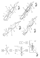
- Des exemples de réalisation de la présente invention vont être décrits en relation avec les figures des planches annexées, dans lesquelles :
- la
fig.1 est un schéma illustrant différentes opérations que comprend une méthode de mise en oeuvre d'un dispositif d'identification d'un objet allongé à identifier de la présente invention. - Les
fig.2 à fig.5 sont des illustrations en perspective de modalités respectives d'enroulement autour d'un objet allongé à identifier de brins d'au moins une antenne dipolaire d'un marqueur à radiofréquences conformément à la présente invention. - la
fig.6 est une illustration en perspective d'un exemple de réalisation d'un substrat flexible à mémoire de forme agencé en ruban torsadé formant des moyens de fixation d'un marqueur à radiofréquences de la présente invention sur un objet à identifier. - les
fig.7 et fig.8 sont des illustrations d'un autre exemple de réalisation d'un substrat flexible à mémoire de forme agencé en plaque souple étirable formant des moyens de fixation d'un marqueur à radiofréquences de la présente invention sur un objet à identifier, représenté respectivement postérieurement et préalablement à la fixation du marqueur à radiofréquences sur l'objet à identifier. - Sur la
fig.1 , un objet à identifier 1 tel qu'un câble, un faisceau de câbles, un conduit ou un profilé, est de conformation allongée dont la longueur L est significativement supérieure à sa plus grande dimension en largeur D. Un tel objet à identifier 1 est installé sur site 2 à bord d'un aéronef en présentant potentiellement divers agencements de sa section transversale, considérée au regard de sa conformation que de ses dimensions en extension transversale. - L'identification de l'objet à identifier 1 est effectuée au moyen d'un dispositif d'identification par coopération entre au moins un marqueur à radiofréquences 3 passif de type RFID et un lecteur 4 actif distant de l'objet à identifier 1 porteur du marqueur à radiofréquences 3. Le marqueur à radiofréquences 3 et le lecteur 4 coopèrent entre eux par échange de radiofréquences 5.
- Compte tenu de son extension en longueur, un même objet à identifier 1 peut comporter plusieurs marqueurs à radiofréquences 3 répartis sur sa longueur et coopérants potentiellement avec un ou plusieurs lecteurs 4 distants de l'objet à identifier 1.
- Le marqueur à radiofréquences 3 comprend au moins une antenne dipolaire 6 dont les brins 7 sont connectés à au moins une puce électronique 8. De tels brins 7 sont préférentiellement choisis agencés en lacet pour favoriser leur enroulement en hélice autour et à la périphérie de l'objet à identifier 1 en évitant leur détérioration lors de l'implantation du marqueur à radiofréquences 3 telle que décrite plus loin. Un même marqueur à radiofréquences 3 peut comporter plusieurs antennes dipolaires 6, qui sont connectées soit à une puce électronique 8 à multiples entrées soit à des puces électroniques 8 respectives indépendantes ou synchronisées.
- Le marqueur à radiofréquences 3 est considéré comme passif car exempt de source d'énergie propre. Le lecteur 4 est considéré comme actif car il fournit à partir dudit échange de radiofréquences 5 l'énergie nécessaire au marqueur à radiofréquences 3 pour activer son fonctionnement.
- Une méthode conforme à la présente invention de mise en oeuvre du dispositif d'identification, comprend une opération classique de fabrication 10 du marqueur à radiofréquences 3 et une opération d'implantation 9 du marqueur à radiofréquences 3 sur l'objet à identifier 1 préalablement à son installation à bord de l'aéronef 2.
- Préalablement à l'opération d'implantation 9 du marqueur à radiofréquences 3 sur l'objet à identifier 1, la méthode comprend une opération de conditionnement 12' du marqueur à radiofréquences 3.
- Selon cette opération de conditionnement 12', le marqueur à radiofréquences 3 est intégré à un substrat flexible 12 à mémoire de forme en vue de son implantation 9 sur l'objet à identifier 1. Le substrat flexible 12 forme des moyens de fixation du marqueur à radiofréquences 3 sur l'objet à identifier 1 par enserrement de l'objet à identifier 1 par le substrat flexible 12 par suite de sa déformation par un opérateur.
- L'intégration au substrat flexible 12 du marqueur à radiofréquences 3 est par exemple réalisée par scellement du marqueur à radiofréquences 3 en surface du substrat flexible 12 ou par exemple encore est réalisée en encapsulant le marqueur à radiofréquences 3 entre deux couches du substrat flexible 12.
- L'objet à identifier 1 étant équipé du marqueur à radiofréquences 3, une opération d'installation 13 de l'objet à identifier 1 est effectuée pour son montage sur site 2 à bord de l'aéronef.
- La méthode comprend encore une opération de placement 14 du lecteur 4 à proximité de l'objet à identifier 1 pour mettre le lecteur 4 en coopération avec le marqueur à radiofréquences 3 par échange de radiofréquences 5 entre eux.
- Par exemple, le lecteur 4 est installé à bord de l'aéronef 2 pour la mise en coopération permanente entre le lecteur 4 et au moins un marqueur à radiofréquences 3 implanté sur l'objet à identifier 1. Le marqueur à radiofréquences 3 et le lecteur 4 sont installés à bord de l'aéronef dans des positions relatives autorisant un échange de radiofréquences 5 entre eux.
- Par exemple encore, le lecteur 4 est éventuellement exploité en cas de besoin par un opérateur approchant le lecteur 4 de l'objet à identifier pour placer le lecteur 4 en coopération avec le marqueur à radiofréquences 3.
- Sur les
fig.1 à fig.8 , un marqueur à radiofréquences 3 comporte au moins une antenne dipolaire 6 dont les brins 7 agencés en lacet sont connectés à une puce électronique 8. Le marqueur à radiofréquences 3 est dédié à être implanté sur un objet à identifier 1 de conformation allongée, par enroulement en hélice des brins 7 de l'antenne dipolaire 6 autour de l'objet à identifier 1. - Sur les
fig.2 à fig.7 , l'enroulement en hélice de chacun des brins 7 autour de l'objet à identifier 1 s'étend suivant l'ensemble des dimensions de l'objet à identifier 1 définissant géométriquement ses dimensions transversales D et sa longueur L. L'une des extrémités des brins 7 est connectée à la puce électronique 8, tandis que leur autre extrémité libre est utilisée pour enrouler en hélice les brins 7 autour de l'objet à identifier 1. Les enroulements respectifs des brins 7 d'une même antenne dipolaire 6 autour de l'objet à identifier 1 sont de préférence homothétiques. - On relèvera que les dimensions d'extension L, D de l'objet à identifier 1 correspondent respectivement à la dimension d'extension en longueur L et à une quelconque dimension d'extension en largeur D des hélices respectivement formées par les brins 7 enroulés autour de l'objet à identifier 1.
- Quelles que soient la position ou l'orientation sur lui-même de l'objet à identifier 1 considéré au regard de sa section transversale, au moins un tronçon de chacun des brins 7 s'étendant suivant au moins un tour d'hélice localement le long et autour de l'objet à identifier 1, est placé par rapport à un lecteur distant de manière à optimiser l'échange de radiofréquences entre eux, et cela quelle que soit la position du lecteur distant par rapport à l'objet à identifier.
- Selon l'agencement propre de l'objet à identifier 1 et en considérant notamment la capacité du support flexible à se déformer élastiquement et/ou la position et l'orientation des brins 7 du marqueur à radiofréquences 3 implanté sur le substrat flexible 12, le nombre de pas d'hélice P formée par chacun des brins 7 d'une antenne dipolaire 6 entourant l'objet à identifier 1 est compris entre 1 et 5. Le pas d'hélice P s'étend par ailleurs suivant l'extension en longueur L de l'hélice d'une valeur comprise entre 1 et 10 fois la plus grande dimension suivant l'extension en largeur D de l'hélice.
- Sur la
fig.2 et lafig.3 , le marqueur à radiofréquences 3 comporte une antenne dipolaire 6 unique. Par ailleurs sur lesfig.2 et fig.4 , les brins 7 conformés en lacet d'au moins une antenne dipolaire 6 sont plus particulièrement agencés en filins, tandis que sur lesfig.3 et fig.5 , les brins 7 conformés en lacet d'au moins une antenne dipolaire 6 sont plus particulièrement de section aplatie. - Sur les
fig.4 à fig.6 , le marqueur à radiofréquences 3 comporte deux antennes dipolaires 6 réparties radialement autour de l'objet à identifier 1. Dans ce cas, les enroulements en hélice respectifs des brins 7 de chacune des antennes dipolaires 6 s'entendent suivant des directions d'enroulement opposées. De telles dispositions permettent d'interdire une superposition par croisement des brins 7 d'antenne 6 entre eux, les brins 7 s'étendant l'un par rapport à l'autre à des côtés opposés de l'objet à identifier 1. - Sur la
fig.6 , le marqueur à radiofréquences 3 est intégré à un substrat flexible 12 à mémoire de forme agencé en ruban torsadé 15. L'agencement en torsade du ruban torsadé 15 confère au substrat flexible 12 son caractère à mémoire de forme. Le ruban torsadé 15 peut être soumis à déformation par un opérateur pour permettre son installation aisée localement sur l'objet à identifier 1, une interruption de ladite déformation provoquant une rétraction spontanée du ruban torsadé 15 qui enserre alors l'objet à identifier 1 à sa périphérie. - Plus particulièrement, le ruban torsadé 15 peut être déformé et être approché par un opérateur latéralement par rapport à l'objet à identifier 1, voire être mis en place progressivement autour de l'objet à identifier 1.
- Les brins 7 d'antenne 6 agencés en lacet sont avantageusement intégrés au substrat flexible 12 en s'étendant suivant l'orientation d'extension des torses du ruban torsadé 15, tel que sur l'exemple illustré le long des bords longitudinaux du ruban torsadé 15.
- Ces dispositions sont telles que l'opération de positionnement en hélice des brins 7 autour de l'objet à identifier 1 en est facilitée. En effet, les brins 7 sont chacun spontanément maintenus suivant une conformation en hélice par le ruban torsadé 15, indépendamment d'une intervention par un opérateur visant spécifiquement à conférer aux brins 7 de l'antenne 6 une conformation en hélice.
- Sur les
fig.7 et fig.8 , le marqueur à radiofréquences est intégré à un substrat flexible 12 agencé en plaque souple 16, telle que formée d'un film étirable en polytétrafluoroéthylène. - Sur la
fig.8 , la plaque souple 16 peut être approchée latéralement par rapport à l'objet à identifier 1 puis être étirée par un opérateur préalablement à son enroulement autour de l'objet à identifier 1. - L'enroulement de la plaque souple 16 autour de l'objet à identifier 1 est effectué par l'opérateur de façon telle que les brins 7 sont chacun enroulés en hélice autour de l'objet à identifier 1, tel que représenté sur la
fig.7 . L'opérateur interrompant l'étirement de la plaque souple 16, celle-ci se rétracte autour de l'objet à identifier 1 en procurant la fixation du marqueur à radiofréquences 3 sur l'objet à identifier 1 par enserrement de l'objet à identifier par le substrat flexible 12 enroulé autour de l'objet à identifier. - Il est à relever que la valeur du pas P de l'hélice et le nombre de tours d'hélice de l'enroulement des brins 7 autour de l'objet à identifier 1 peuvent être déterminés en fonction de la section transversale connue de l'objet à identifier, en faisant varier l'orientation de la plaque souple 16 par rapport à la direction d'extension en longueur L de l'objet à identifier 1.
Claims (12)
- Dispositif d'identification d'un objet à identifier (1) de conformation allongée, ledit dispositif comprenant au moins un marqueur à radiofréquences (3) coopérant avec un lecteur (4) par échange entre eux de radiofréquences (5), ledit au moins un marqueur à radiofréquences (3) étant intégré à un substrat flexible (12) et comportant au moins une antenne dipolaire (6) à brins (7) connectés à au moins une puce électronique (8), le marqueur à radiofréquences (3) étant muni de moyens de fixation sur l'objet à identifier (1) aptes à maintenir en conformation autour de l'objet à identifier (1) chacun des brins (7) de l'antenne dipolaire (6) selon un enroulement en hélice à au moins un tour,
caractérisé en ce que lesdits moyens de fixation sont formés par le substrat flexible (12) qui est à mémoire de forme, lesdits moyens de fixation étant du type à enserrement de l'objet à identifier (1) par rétraction du substrat flexible (12) consécutivement à son étirement autour de l'objet à identifier (1). - Dispositif selon la revendication 1,
caractérisé en ce que le substrat flexible (12) est élastiquement déformable en étant agencé en ruban torsadé (15), le marqueur à radiofréquences (3) étant intégré au substrat flexible (12) selon une orientation des brins (7) s'étendant suivant l'orientation des torses du ruban torsadé (15). - Dispositif selon la revendication 1,
caractérisé en ce que le substrat flexible (12) est agencé en plaque souple (16) élastiquement déformable issue d'un matériau thermoplastique. - Dispositif selon la revendication 3,
caractérisé en ce que le matériau thermoplastique dont est issu le substrat flexible est le polytétrafluoroéthylène (PTFE). - Dispositif selon la revendication 1,
caractérisé en ce que le substrat flexible (12) est issu d'un matériau plastique à mémoire de forme (SMP d'après l'acronyme anglais Shape Memory Plastics) procurant un enserrement de l'objet à identifier (1) à température ambiante consécutivement à une déformation du substrat flexible (12) provoquée par sa mise à température de commutation indifféremment supérieure ou inférieure à un seuil de température défini pour une température ambiante prédéterminée du substrat flexible (12). - Dispositif selon la revendication 5,
caractérisé en ce que le matériau plastique à mémoire de forme est un polyuréthane thermoplastique. - Dispositif selon l'une quelconque des revendications 1 à 6,
caractérisé en ce que le marqueur à radiofréquences (3) est rapporté en surface du substrat flexible (12). - Dispositif selon l'une quelconque des revendications 1 et 6,
caractérisé en ce que le marqueur à radiofréquences (3) est encapsulé à l'intérieur du substrat flexible (12). - Dispositif selon l'une quelconque des revendications 1 à 8,
caractérisé en ce que la disposition et l'orientation individuelle des brins (7) sur le substrat flexible (12) sont définies aptes à procurer, en une quelconque position maintenue enroulée du substrat flexible (12) sur lui-même, un enroulement en hélice de chacun des dits brins (7) s'étendant suivant un pas d'hélice (P) au moins égal à N1 fois la largeur de l'enroulement, N1 étant compris entre 1 et 10. - Dispositif selon l'une quelconque des revendications 1 à 9,
caractérisé en ce que la disposition et l'orientation individuelle des brins (7) sur le substrat flexible (12) sont définies aptes à procurer, en une quelconque position maintenue enroulée du substrat flexible (12) sur lui-même, un enroulement en hélice de chacun des dits brins (7) s'étendant suivant N2 pas d'hélice, N2 étant compris entre 1 et 5. - Dispositif selon l'une quelconque des revendications 1 à 10,
caractérisé en ce que le marqueur à radiofréquences (3) comportant une pluralité d'antennes dipolaires (6), la disposition et l'orientation de chacun des brins (7) de chacune des antennes dipolaires (6) confèrent, en une quelconque position enroulée du substrat flexible (12) sur lui-même, un enroulement en hélice des brins (7) de chacune des antennes dipolaires (6) suivant des directions d'enroulement opposées interdisant une superposition par croisement des brins (7) des antennes dipolaires (6) entre eux. - Méthode de mise en oeuvre d'un dispositif selon l'une quelconque des revendications 1 à 11,
caractérisée en ce que ladite méthode comprend les opérations suivantes :- ) une opération de fabrication du marqueur à radiofréquences (3) comprenant la puce électronique (8) à laquelle sont connectés chacun des brins (7) de ladite au moins une antenne dipolaire (6),- ) une opération de conditionnement du marqueur à radiofréquences (3) par intégration au substrat flexible (12) à mémoire de forme, indifféremment par scellement du marqueur à radiofréquences (3) en surface du substrat flexible (12) ou par encapsulation du marqueur à radiofréquences (3) entre deux couches du substrat flexible (12),- ) une opération d'implantation du marqueur à radiofréquences (3) par un opérateur sur l'objet à identifier (1), par déformation et par positionnement du substrat flexible (12) à l'état déformé localement autour de l'objet à identifier (1) de sorte que chacun des brins (7) d'antenne soit disposé suivant un enroulement en hélice à au moins un tour autour de l'objet à identifier (1), puis par interruption de la déformation par l'opérateur du substrat flexible (12) induisant sa mise à l'état rétracté provoquant un enserrement de l'objet à identifier (1) par le substrat flexible (12), puis- ) une opération d'identification de l'objet à identifier (1), par placement du lecteur (4) à proximité de l'objet à identifier (1) jusqu'à obtenir un échange pertinent de radiofréquences (5) entre le lecteur (4) et le marqueur à radiofréquences (3).
Applications Claiming Priority (1)
| Application Number | Priority Date | Filing Date | Title |
|---|---|---|---|
| FR1300243A FR3001820B1 (fr) | 2013-02-06 | 2013-02-06 | Procede d'identification par radiofrequences d'un objet cylindrique tel qu'un cable ou un conduit equipant notamment un aeronef |
Publications (2)
| Publication Number | Publication Date |
|---|---|
| EP2765537A1 true EP2765537A1 (fr) | 2014-08-13 |
| EP2765537B1 EP2765537B1 (fr) | 2017-11-08 |
Family
ID=48856676
Family Applications (1)
| Application Number | Title | Priority Date | Filing Date |
|---|---|---|---|
| EP14000409.4A Active EP2765537B1 (fr) | 2013-02-06 | 2014-02-04 | Dispositif d'identification par radiofréquences d'objets allongés montés à bord d'un aéronef, tel que des câbles ou des conduits |
Country Status (2)
| Country | Link |
|---|---|
| EP (1) | EP2765537B1 (fr) |
| FR (1) | FR3001820B1 (fr) |
Cited By (5)
| Publication number | Priority date | Publication date | Assignee | Title |
|---|---|---|---|---|
| WO2017013370A1 (fr) * | 2015-07-21 | 2017-01-26 | Systemes Et Technologies Identification (Stid) | Dispositif de radio-identification pour un élément à identifier de forme tubulaire en environnement contraignant |
| US11017185B2 (en) | 2016-11-16 | 2021-05-25 | Avery Dennison Retail Information Services Llc | Programming and testing of wire RFID tags |
| IT202100001484A1 (it) * | 2021-01-26 | 2022-07-26 | Pearfid Soc A Responsabilita Limitata Semplificata | Metodo per la realizzazione di dispositivi transponder rfid |
| CN115104101A (zh) * | 2019-12-28 | 2022-09-23 | 艾利丹尼森零售信息服务有限公司 | 具有刚度可变结构的无线通信装置 |
| WO2023274456A1 (fr) * | 2021-06-29 | 2023-01-05 | Contitech Techno-Chemie Gmbh | Élément d'identification pour lignes multimédia |
Citations (5)
| Publication number | Priority date | Publication date | Assignee | Title |
|---|---|---|---|---|
| US20060186210A1 (en) * | 2005-02-23 | 2006-08-24 | Sdgi Holdings, Inc. | Sleeve-type RFID tag |
| US20060208900A1 (en) | 2005-01-19 | 2006-09-21 | X-Ether, Inc. | Rfid antenna |
| GB2467185A (en) | 2009-01-27 | 2010-07-28 | Navigator Systems Ltd | Antenna Arrangement of RFID Tag |
| EP2328108A2 (fr) | 2006-12-20 | 2011-06-01 | Symbol Technologies, Inc. | Surface à sélectivité de fréquences facilitant la mise en oeuvre de produits d'identification par radiofréquences |
| FR2962589A1 (fr) | 2010-07-06 | 2012-01-13 | Labinal | Reperage de cablage dans un aeronef |
-
2013
- 2013-02-06 FR FR1300243A patent/FR3001820B1/fr active Active
-
2014
- 2014-02-04 EP EP14000409.4A patent/EP2765537B1/fr active Active
Patent Citations (5)
| Publication number | Priority date | Publication date | Assignee | Title |
|---|---|---|---|---|
| US20060208900A1 (en) | 2005-01-19 | 2006-09-21 | X-Ether, Inc. | Rfid antenna |
| US20060186210A1 (en) * | 2005-02-23 | 2006-08-24 | Sdgi Holdings, Inc. | Sleeve-type RFID tag |
| EP2328108A2 (fr) | 2006-12-20 | 2011-06-01 | Symbol Technologies, Inc. | Surface à sélectivité de fréquences facilitant la mise en oeuvre de produits d'identification par radiofréquences |
| GB2467185A (en) | 2009-01-27 | 2010-07-28 | Navigator Systems Ltd | Antenna Arrangement of RFID Tag |
| FR2962589A1 (fr) | 2010-07-06 | 2012-01-13 | Labinal | Reperage de cablage dans un aeronef |
Cited By (7)
| Publication number | Priority date | Publication date | Assignee | Title |
|---|---|---|---|---|
| WO2017013370A1 (fr) * | 2015-07-21 | 2017-01-26 | Systemes Et Technologies Identification (Stid) | Dispositif de radio-identification pour un élément à identifier de forme tubulaire en environnement contraignant |
| FR3039299A1 (fr) * | 2015-07-21 | 2017-01-27 | Systemes Et Tech Identification (Stid) | Dispositif de radio-identification pour un element a identifier de forme tubulaire en environnement contraignant |
| US10217041B2 (en) | 2015-07-21 | 2019-02-26 | Systemes Et Technologies Identification (Stid) | Radio-frequency identification device for a tubular element to be identified in a constrained environment |
| US11017185B2 (en) | 2016-11-16 | 2021-05-25 | Avery Dennison Retail Information Services Llc | Programming and testing of wire RFID tags |
| CN115104101A (zh) * | 2019-12-28 | 2022-09-23 | 艾利丹尼森零售信息服务有限公司 | 具有刚度可变结构的无线通信装置 |
| IT202100001484A1 (it) * | 2021-01-26 | 2022-07-26 | Pearfid Soc A Responsabilita Limitata Semplificata | Metodo per la realizzazione di dispositivi transponder rfid |
| WO2023274456A1 (fr) * | 2021-06-29 | 2023-01-05 | Contitech Techno-Chemie Gmbh | Élément d'identification pour lignes multimédia |
Also Published As
| Publication number | Publication date |
|---|---|
| FR3001820B1 (fr) | 2016-06-10 |
| EP2765537B1 (fr) | 2017-11-08 |
| FR3001820A1 (fr) | 2014-08-08 |
Similar Documents
| Publication | Publication Date | Title |
|---|---|---|
| EP2765537B1 (fr) | Dispositif d'identification par radiofréquences d'objets allongés montés à bord d'un aéronef, tel que des câbles ou des conduits | |
| JP7317132B2 (ja) | タイヤのための改善したrfidデバイス | |
| JP2022132668A (ja) | 非接触通信のためのプラスチックパッケージに入れたrfidトランスポンダ | |
| EP2867831A1 (fr) | Procede de fabrication d'un microcircuit sans contact | |
| US20180157953A1 (en) | Systems and methods for improving performance of rfid tags | |
| KR101802395B1 (ko) | 안테나용 케이블 홀더 및 안테나용 케이블 홀더를 포함하는 안테나 | |
| US10468762B1 (en) | Versatile antenna wire and methods of manufacturing | |
| US10748052B2 (en) | Apparatus and method for making antennas for radio-frequency identifying devices | |
| CN103682675B (zh) | 一种喇叭天线 | |
| US10790654B2 (en) | Support structure for supporting a wire | |
| US9452700B2 (en) | Method for manufacturing a suspension mat | |
| US20170162293A1 (en) | Wire harness | |
| EP2787586B1 (fr) | Ensemble d'installation pour relier un harnais de câble ou similaire entre deux éléments de structure d'avion | |
| EP3133620A1 (fr) | Dispositif pour la formation d'une bobine toroïdale et procédé pour la formation d'une bobine toroïdale | |
| EP2784786A1 (fr) | Câble et procédé pour fabriquer un câble | |
| EP4174880A1 (fr) | Cable de puissance equipe d'une pluralite de dispositifs electroniques d'identification par radiofrequence et procede de fabrication associe | |
| US9048003B2 (en) | Self-supporting cable | |
| KR101982384B1 (ko) | Espar 안테나 | |
| JPH09198941A (ja) | 漏洩同軸ケーブルの製造方法 | |
| JP5189761B2 (ja) | 漏洩同軸ケーブルとその製造方法 | |
| EP3326113B1 (fr) | Dispositif de radio-identification pour un élément à identifier de forme tubulaire en environnement contraignant | |
| KR101276075B1 (ko) | 동축케이블 일체형 모노폴 안테나 | |
| FI72221C (fi) | Flexibla elkablar med korrugerad isolering och foerfarande foer deras framstaellning. | |
| US8884162B2 (en) | Conductive element and method for manufacturing the same | |
| KR102469246B1 (ko) | 지반 매립형 안테나 |
Legal Events
| Date | Code | Title | Description |
|---|---|---|---|
| PUAI | Public reference made under article 153(3) epc to a published international application that has entered the european phase |
Free format text: ORIGINAL CODE: 0009012 |
|
| 17P | Request for examination filed |
Effective date: 20140204 |
|
| AK | Designated contracting states |
Kind code of ref document: A1 Designated state(s): AL AT BE BG CH CY CZ DE DK EE ES FI FR GB GR HR HU IE IS IT LI LT LU LV MC MK MT NL NO PL PT RO RS SE SI SK SM TR |
|
| AX | Request for extension of the european patent |
Extension state: BA ME |
|
| RBV | Designated contracting states (corrected) |
Designated state(s): AL AT BE BG CH CY CZ DE DK EE ES FI FR GB GR HR HU IE IS IT LI LT LU LV MC MK MT NL NO PL PT RO RS SE SI SK SM TR |
|
| R17P | Request for examination filed (corrected) |
Effective date: 20141002 |
|
| RBV | Designated contracting states (corrected) |
Designated state(s): AL AT BE BG CH CY CZ DE DK EE ES FI FR GB GR HR HU IE IS IT LI LT LU LV MC MK MT NL NO PL PT RO RS SE SI SK SM TR |
|
| GRAP | Despatch of communication of intention to grant a patent |
Free format text: ORIGINAL CODE: EPIDOSNIGR1 |
|
| INTG | Intention to grant announced |
Effective date: 20170725 |
|
| GRAS | Grant fee paid |
Free format text: ORIGINAL CODE: EPIDOSNIGR3 |
|
| GRAA | (expected) grant |
Free format text: ORIGINAL CODE: 0009210 |
|
| AK | Designated contracting states |
Kind code of ref document: B1 Designated state(s): AL AT BE BG CH CY CZ DE DK EE ES FI FR GB GR HR HU IE IS IT LI LT LU LV MC MK MT NL NO PL PT RO RS SE SI SK SM TR |
|
| REG | Reference to a national code |
Ref country code: GB Ref legal event code: FG4D Free format text: NOT ENGLISH |
|
| REG | Reference to a national code |
Ref country code: CH Ref legal event code: EP Ref country code: AT Ref legal event code: REF Ref document number: 944819 Country of ref document: AT Kind code of ref document: T Effective date: 20171115 |
|
| REG | Reference to a national code |
Ref country code: IE Ref legal event code: FG4D Free format text: LANGUAGE OF EP DOCUMENT: FRENCH |
|
| REG | Reference to a national code |
Ref country code: DE Ref legal event code: R096 Ref document number: 602014016784 Country of ref document: DE |
|
| REG | Reference to a national code |
Ref country code: FR Ref legal event code: PLFP Year of fee payment: 5 |
|
| REG | Reference to a national code |
Ref country code: NL Ref legal event code: MP Effective date: 20171108 |
|
| REG | Reference to a national code |
Ref country code: LT Ref legal event code: MG4D |
|
| REG | Reference to a national code |
Ref country code: AT Ref legal event code: MK05 Ref document number: 944819 Country of ref document: AT Kind code of ref document: T Effective date: 20171108 |
|
| PG25 | Lapsed in a contracting state [announced via postgrant information from national office to epo] |
Ref country code: LT Free format text: LAPSE BECAUSE OF FAILURE TO SUBMIT A TRANSLATION OF THE DESCRIPTION OR TO PAY THE FEE WITHIN THE PRESCRIBED TIME-LIMIT Effective date: 20171108 Ref country code: NL Free format text: LAPSE BECAUSE OF FAILURE TO SUBMIT A TRANSLATION OF THE DESCRIPTION OR TO PAY THE FEE WITHIN THE PRESCRIBED TIME-LIMIT Effective date: 20171108 Ref country code: ES Free format text: LAPSE BECAUSE OF FAILURE TO SUBMIT A TRANSLATION OF THE DESCRIPTION OR TO PAY THE FEE WITHIN THE PRESCRIBED TIME-LIMIT Effective date: 20171108 Ref country code: NO Free format text: LAPSE BECAUSE OF FAILURE TO SUBMIT A TRANSLATION OF THE DESCRIPTION OR TO PAY THE FEE WITHIN THE PRESCRIBED TIME-LIMIT Effective date: 20180208 Ref country code: FI Free format text: LAPSE BECAUSE OF FAILURE TO SUBMIT A TRANSLATION OF THE DESCRIPTION OR TO PAY THE FEE WITHIN THE PRESCRIBED TIME-LIMIT Effective date: 20171108 Ref country code: SE Free format text: LAPSE BECAUSE OF FAILURE TO SUBMIT A TRANSLATION OF THE DESCRIPTION OR TO PAY THE FEE WITHIN THE PRESCRIBED TIME-LIMIT Effective date: 20171108 |
|
| PG25 | Lapsed in a contracting state [announced via postgrant information from national office to epo] |
Ref country code: IS Free format text: LAPSE BECAUSE OF FAILURE TO SUBMIT A TRANSLATION OF THE DESCRIPTION OR TO PAY THE FEE WITHIN THE PRESCRIBED TIME-LIMIT Effective date: 20180308 Ref country code: LV Free format text: LAPSE BECAUSE OF FAILURE TO SUBMIT A TRANSLATION OF THE DESCRIPTION OR TO PAY THE FEE WITHIN THE PRESCRIBED TIME-LIMIT Effective date: 20171108 Ref country code: BG Free format text: LAPSE BECAUSE OF FAILURE TO SUBMIT A TRANSLATION OF THE DESCRIPTION OR TO PAY THE FEE WITHIN THE PRESCRIBED TIME-LIMIT Effective date: 20180208 Ref country code: GR Free format text: LAPSE BECAUSE OF FAILURE TO SUBMIT A TRANSLATION OF THE DESCRIPTION OR TO PAY THE FEE WITHIN THE PRESCRIBED TIME-LIMIT Effective date: 20180209 Ref country code: RS Free format text: LAPSE BECAUSE OF FAILURE TO SUBMIT A TRANSLATION OF THE DESCRIPTION OR TO PAY THE FEE WITHIN THE PRESCRIBED TIME-LIMIT Effective date: 20171108 Ref country code: HR Free format text: LAPSE BECAUSE OF FAILURE TO SUBMIT A TRANSLATION OF THE DESCRIPTION OR TO PAY THE FEE WITHIN THE PRESCRIBED TIME-LIMIT Effective date: 20171108 Ref country code: AT Free format text: LAPSE BECAUSE OF FAILURE TO SUBMIT A TRANSLATION OF THE DESCRIPTION OR TO PAY THE FEE WITHIN THE PRESCRIBED TIME-LIMIT Effective date: 20171108 |
|
| PG25 | Lapsed in a contracting state [announced via postgrant information from national office to epo] |
Ref country code: SK Free format text: LAPSE BECAUSE OF FAILURE TO SUBMIT A TRANSLATION OF THE DESCRIPTION OR TO PAY THE FEE WITHIN THE PRESCRIBED TIME-LIMIT Effective date: 20171108 Ref country code: CZ Free format text: LAPSE BECAUSE OF FAILURE TO SUBMIT A TRANSLATION OF THE DESCRIPTION OR TO PAY THE FEE WITHIN THE PRESCRIBED TIME-LIMIT Effective date: 20171108 Ref country code: EE Free format text: LAPSE BECAUSE OF FAILURE TO SUBMIT A TRANSLATION OF THE DESCRIPTION OR TO PAY THE FEE WITHIN THE PRESCRIBED TIME-LIMIT Effective date: 20171108 Ref country code: CY Free format text: LAPSE BECAUSE OF FAILURE TO SUBMIT A TRANSLATION OF THE DESCRIPTION OR TO PAY THE FEE WITHIN THE PRESCRIBED TIME-LIMIT Effective date: 20171108 Ref country code: DK Free format text: LAPSE BECAUSE OF FAILURE TO SUBMIT A TRANSLATION OF THE DESCRIPTION OR TO PAY THE FEE WITHIN THE PRESCRIBED TIME-LIMIT Effective date: 20171108 |
|
| REG | Reference to a national code |
Ref country code: DE Ref legal event code: R097 Ref document number: 602014016784 Country of ref document: DE |
|
| PG25 | Lapsed in a contracting state [announced via postgrant information from national office to epo] |
Ref country code: PL Free format text: LAPSE BECAUSE OF FAILURE TO SUBMIT A TRANSLATION OF THE DESCRIPTION OR TO PAY THE FEE WITHIN THE PRESCRIBED TIME-LIMIT Effective date: 20171108 Ref country code: RO Free format text: LAPSE BECAUSE OF FAILURE TO SUBMIT A TRANSLATION OF THE DESCRIPTION OR TO PAY THE FEE WITHIN THE PRESCRIBED TIME-LIMIT Effective date: 20171108 Ref country code: SM Free format text: LAPSE BECAUSE OF FAILURE TO SUBMIT A TRANSLATION OF THE DESCRIPTION OR TO PAY THE FEE WITHIN THE PRESCRIBED TIME-LIMIT Effective date: 20171108 |
|
| REG | Reference to a national code |
Ref country code: DE Ref legal event code: R119 Ref document number: 602014016784 Country of ref document: DE |
|
| PLBE | No opposition filed within time limit |
Free format text: ORIGINAL CODE: 0009261 |
|
| REG | Reference to a national code |
Ref country code: CH Ref legal event code: PL |
|
| STAA | Information on the status of an ep patent application or granted ep patent |
Free format text: STATUS: NO OPPOSITION FILED WITHIN TIME LIMIT |
|
| PG25 | Lapsed in a contracting state [announced via postgrant information from national office to epo] |
Ref country code: MC Free format text: LAPSE BECAUSE OF FAILURE TO SUBMIT A TRANSLATION OF THE DESCRIPTION OR TO PAY THE FEE WITHIN THE PRESCRIBED TIME-LIMIT Effective date: 20171108 Ref country code: MT Free format text: LAPSE BECAUSE OF FAILURE TO SUBMIT A TRANSLATION OF THE DESCRIPTION OR TO PAY THE FEE WITHIN THE PRESCRIBED TIME-LIMIT Effective date: 20171108 |
|
| 26N | No opposition filed |
Effective date: 20180809 |
|
| GBPC | Gb: european patent ceased through non-payment of renewal fee |
Effective date: 20180208 |
|
| REG | Reference to a national code |
Ref country code: IE Ref legal event code: MM4A |
|
| REG | Reference to a national code |
Ref country code: BE Ref legal event code: MM Effective date: 20180228 |
|
| PG25 | Lapsed in a contracting state [announced via postgrant information from national office to epo] |
Ref country code: LU Free format text: LAPSE BECAUSE OF NON-PAYMENT OF DUE FEES Effective date: 20180204 Ref country code: SI Free format text: LAPSE BECAUSE OF FAILURE TO SUBMIT A TRANSLATION OF THE DESCRIPTION OR TO PAY THE FEE WITHIN THE PRESCRIBED TIME-LIMIT Effective date: 20171108 Ref country code: LI Free format text: LAPSE BECAUSE OF NON-PAYMENT OF DUE FEES Effective date: 20180228 Ref country code: CH Free format text: LAPSE BECAUSE OF NON-PAYMENT OF DUE FEES Effective date: 20180228 |
|
| PG25 | Lapsed in a contracting state [announced via postgrant information from national office to epo] |
Ref country code: IE Free format text: LAPSE BECAUSE OF NON-PAYMENT OF DUE FEES Effective date: 20180204 Ref country code: DE Free format text: LAPSE BECAUSE OF NON-PAYMENT OF DUE FEES Effective date: 20180901 |
|
| PG25 | Lapsed in a contracting state [announced via postgrant information from national office to epo] |
Ref country code: GB Free format text: LAPSE BECAUSE OF NON-PAYMENT OF DUE FEES Effective date: 20180208 Ref country code: BE Free format text: LAPSE BECAUSE OF NON-PAYMENT OF DUE FEES Effective date: 20180228 |
|
| PG25 | Lapsed in a contracting state [announced via postgrant information from national office to epo] |
Ref country code: TR Free format text: LAPSE BECAUSE OF FAILURE TO SUBMIT A TRANSLATION OF THE DESCRIPTION OR TO PAY THE FEE WITHIN THE PRESCRIBED TIME-LIMIT Effective date: 20171108 |
|
| PG25 | Lapsed in a contracting state [announced via postgrant information from national office to epo] |
Ref country code: PT Free format text: LAPSE BECAUSE OF FAILURE TO SUBMIT A TRANSLATION OF THE DESCRIPTION OR TO PAY THE FEE WITHIN THE PRESCRIBED TIME-LIMIT Effective date: 20171108 Ref country code: HU Free format text: LAPSE BECAUSE OF FAILURE TO SUBMIT A TRANSLATION OF THE DESCRIPTION OR TO PAY THE FEE WITHIN THE PRESCRIBED TIME-LIMIT; INVALID AB INITIO Effective date: 20140204 |
|
| PG25 | Lapsed in a contracting state [announced via postgrant information from national office to epo] |
Ref country code: MK Free format text: LAPSE BECAUSE OF NON-PAYMENT OF DUE FEES Effective date: 20171108 |
|
| PG25 | Lapsed in a contracting state [announced via postgrant information from national office to epo] |
Ref country code: AL Free format text: LAPSE BECAUSE OF FAILURE TO SUBMIT A TRANSLATION OF THE DESCRIPTION OR TO PAY THE FEE WITHIN THE PRESCRIBED TIME-LIMIT Effective date: 20171108 |
|
| P01 | Opt-out of the competence of the unified patent court (upc) registered |
Effective date: 20230530 |
|
| PGFP | Annual fee paid to national office [announced via postgrant information from national office to epo] |
Ref country code: IT Payment date: 20260224 Year of fee payment: 13 |
|
| PGFP | Annual fee paid to national office [announced via postgrant information from national office to epo] |
Ref country code: FR Payment date: 20260218 Year of fee payment: 13 |