EP2765463A2 - Mechanismus zur Übertragung von Achsen- und Drehbewegungen zwischen zwei verschobenen Achsen, und Uhr, die mit einem solchen Mechanismus ausgestattet ist - Google Patents
Mechanismus zur Übertragung von Achsen- und Drehbewegungen zwischen zwei verschobenen Achsen, und Uhr, die mit einem solchen Mechanismus ausgestattet ist Download PDFInfo
- Publication number
- EP2765463A2 EP2765463A2 EP20140151247 EP14151247A EP2765463A2 EP 2765463 A2 EP2765463 A2 EP 2765463A2 EP 20140151247 EP20140151247 EP 20140151247 EP 14151247 A EP14151247 A EP 14151247A EP 2765463 A2 EP2765463 A2 EP 2765463A2
- Authority
- EP
- European Patent Office
- Prior art keywords
- connecting piece
- mechanism according
- transmission mechanism
- rod
- winding
- Prior art date
- Legal status (The legal status is an assumption and is not a legal conclusion. Google has not performed a legal analysis and makes no representation as to the accuracy of the status listed.)
- Granted
Links
- 230000007246 mechanism Effects 0.000 title claims abstract description 49
- 230000015572 biosynthetic process Effects 0.000 claims abstract description 14
- 230000005540 biological transmission Effects 0.000 claims description 23
- 238000004804 winding Methods 0.000 abstract description 70
- 238000000926 separation method Methods 0.000 abstract description 2
- 230000005489 elastic deformation Effects 0.000 description 3
- 238000010276 construction Methods 0.000 description 2
- 238000006073 displacement reaction Methods 0.000 description 2
- 208000031968 Cadaver Diseases 0.000 description 1
- 229910000639 Spring steel Inorganic materials 0.000 description 1
- 230000003213 activating effect Effects 0.000 description 1
- 238000012937 correction Methods 0.000 description 1
- 230000008878 coupling Effects 0.000 description 1
- 238000010168 coupling process Methods 0.000 description 1
- 238000005859 coupling reaction Methods 0.000 description 1
- 230000000694 effects Effects 0.000 description 1
- 238000003780 insertion Methods 0.000 description 1
- 230000037431 insertion Effects 0.000 description 1
- 238000004519 manufacturing process Methods 0.000 description 1
- 239000000463 material Substances 0.000 description 1
- 210000000056 organ Anatomy 0.000 description 1
Images
Classifications
-
- G—PHYSICS
- G04—HOROLOGY
- G04B—MECHANICALLY-DRIVEN CLOCKS OR WATCHES; MECHANICAL PARTS OF CLOCKS OR WATCHES IN GENERAL; TIME PIECES USING THE POSITION OF THE SUN, MOON OR STARS
- G04B37/00—Cases
- G04B37/06—Forming the passage for the winding stem through the case; Divided winding stems
- G04B37/066—Divided stem (tige brisee)
Definitions
- the present invention relates to a mechanism for transmitting axial and rotary movements between two offset axes finding a particular application in a mechanism for setting the time and winding of a timepiece and more particularly to such a mechanism comprising a crown of winding operating a winding and setting time.
- the present invention relates to such a mechanism whose winding stem and setting time is in two parts of axes located in parallel planes but offset with respect to each other.
- Such mechanisms of winding and setting time rod stem two offset parts are particularly useful for complicated movements, including modular, because in such movements the winding stem is offset from the median plane of the movement. which is a disadvantage from the practical and especially aesthetic point of view.
- the incumbent has developed such a mechanism for transmitting axial and rotary movements between two axes, in particular a winding and setting mechanism comprising a winding rod in two parts of axes located in parallel planes kinematically connected in rotation and in translation but which avoids a reversal of the direction of rotation of the two parts of the winding rod and which facilitates the casing of the movement in the watch case.
- This mechanism comprises a movable assembly movable axially, the second portion of the rod carrying a second pinion and being arranged to be pivoted on said movable assembly but axially integral with the mobile assembly; the first portion of the rod being arranged to be pivoted on the movable assembly but axially integral therewith is secured to a first pinion; an odd number of pivots rotated on the moving assembly kinematically connecting the first pinion to the second pinion.
- this mechanism has a disadvantage that is its size because the movable assembly consists of two plates secured together and in parallel planes using rivets. This moving assembly is necessarily thick and requires a large space between the middle of the watch case and movement. Another disadvantage of this construction is that it requires the use of a casing ring.
- the transmission mechanism according to the invention aims to obviate the disadvantages of existing similar mechanisms.
- the object of the present invention is to provide a mechanism for transmitting axial and rotary movements between two parts of an offset shaft having a movable assembly consisting of a preferably planar connecting piece comprising two elements, at least one is elastic forming with the body of this connecting piece two bearings; each of the portions of said rod having an end carrying a pinion and being arranged to be pivoted in one of said two bearings.
- This mechanism is distinguished by the fact that one or the elastic elements has a locking extension terminated by a hook cooperating with a locking formation of the body of said connecting piece; and in that when the hook is engaged in the locking formation or the two elastic members are locked in the operating position can no longer deviate from the body of the connecting piece.
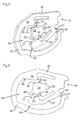
- the transmission mechanism equips a timepiece which comprises a bottom 1, a caseband 2 and an ice 3 inside which is mounted a clockwork movement 4 equipped with an additional module 5 located between the movement 4 and a dial 7.
- the first part 8 of the winding stem, part of the movement 4 is located much lower than the median plane of this timepiece because of the extra thickness due to the module 5.
- the first part 8 of the stem of winding allows to go up by a conventional wheel barrel movement when this part 8 of the winding stem is in the winding position and to proceed to the time when it is in the position of setting time traditional.
- the middle part 2 is crossed by a tube 6 whose axis is situated in the median plane of the timepiece in which the second part 9 of the winding stem slides and rotates, the outer end of which has a thread 10 serving to fix the hub 11 of a winding crown.
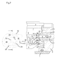
- the outer end of the first portion 8 of the winding stem is formed of a first pinion 13 from a workpiece with this first portion 8 of the winding stem. In the immediate vicinity of this first pinion 13 this first portion 8 of the winding stem has a groove 14. This outer end of the first portion 8 of the rod, formed by the first pinion 13, is free and does not cooperate in any way with the middle 2 of the box shows what greatly facilitates device assembly and after-sales service operations.
- the inner end of the second portion 9 of the winding stem comprises a guide pin 15 and a stop 16 from a workpiece with this second portion of the winding stem.
- This inner end of this second portion 9 of the winding stem further comprises a second pinion 17 coming from a workpiece with this second portion 9 of the winding stem separated from the abutment 16 by a groove 18.
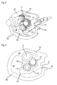
- the mechanism for transmitting axial and rotary movements between the two parts 8, 9 of the winding stem further comprises a mobile link assembly consisting of a preferably planar piece 19 having a general shape in an oval.
- the thickness of this connecting piece 19 corresponds to the width of the grooves 14 and 18 of the first 8 and second 9 parts of the winding stem.
- This connecting piece 19 comprises a bore 20 receiving the axis of a return 21 pivoted on this connecting piece 19.
- This connecting piece 19, plane in the illustrated example, comprises a rigid central body 22 and a first element 23 formed by an arm whose end is integral, generally coming from a workpiece, with the rigid central body 22.
- the free end of this first elastic element comprises a first cylindrical face 24 facing a second cylindrical face 25 carried by the rigid central body 22 of the connecting piece 19.
- the first 24 and second 25 cylindrical surfaces of this first element or arm 23 constitute a bearing receiving the outer end of the first rod portion 8.
- This first element or arm 23 may be rigid or elastic for lateral introduction of the first portion 8 of the rod into its bearing 24, 25.
- this first element or arm 23 When this first element or arm 23 is elastic, it comprises a bearing surface 26 which, as will be seen below, prevents, in the locked position of the connecting piece 19, any separation of this first elastic arm from the rigid central body 22 of the connecting piece 19.
- the free end of the first elastic arm 23 further comprises a first oblique face 27 facing a second oblique face 28 carried by the rigid central body 22 of the connecting piece 19 and forming with the first oblique face 27 of the first arm elastically an insertion slide of the groove 14 of the first rod portion 8 in its bearing formed by the first and second cylindrical surfaces 24, 25.
- the bearing of the first portion 8 of the rod may be formed by a bore formed in the rigid body 22 replacing the cylindrical surfaces 24 and 25.
- the oblique surfaces 27, 28 are removed and the first portion 8 of the rod comprises a first pinion 13 attached, fixed to the end of this first portion 8 of the rod after the inner end of the it has been threaded into said piercing of the rigid body 22.
- This connecting piece 19 further comprises a second element or elastic arm 30 integral, or integrally, with the rigid central portion 22 of this connecting piece 19 by one of its ends.
- the free end of this second elastic arm 30 comprises a head 29 having a third cylindrical face 31 facing a fourth cylindrical face 32 carried by the rigid central body 22 of the connecting piece 19 .
- These third and fourth faces cylindrical 31, 32 form a bearing for the second portion 9 of the rod and fit into the groove 18 of the second portion of rod 9.
- the second portion 9 of the rod is pivoted on the connecting piece and axially secured of it.
- the first gear 13 meshes with the gear 21 which itself meshes with the second gear 17 thus kinematically connecting the first shaft portion 8 to the second shaft portion 9; these two rod portions 8, 9 are also secured axially by the connecting piece 19.
- the second portion 9 of the rod screwed into the hub 11 of winding crown is guided in the tube 6 and its inner end has no need to be guided in the movement 4.
- the head 29 of the second elastic arm 30 has a third oblique face 33 facing a fourth oblique face 34 carried by the rigid central body 22 of the connecting piece 19.
- These third and fourth oblique faces 33, 34 form a slide introducing the groove 18 of the second portion 9 of the rod into the bearing formed by the third and fourth cylindrical surfaces 31, 32.
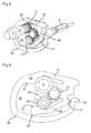
- the head 29 of the second element or elastic arm 30 is integral with a locking extension 35 surrounding the rigid central body 22 and the first elastic arm 23 to end with a hook 36 cooperating with a locking formation 37 carried by the central body 22 near the root of the first elastic arm 23 is its end connected to the rigid central body 22.
- the portion of the locking extension 35 located in front of the rigid central body 22 and the free end of the first elastic arm household an empty portion 38 of sufficient size to successively introduce the first and second pinions 13, 17 during their mounting on the connecting piece 19.
- this first portion 8 of the winding stem is placed perpendicularly to the plane of the connecting piece 19 so that its groove 14 is opposite the first and second oblique faces 27, 28 of the connecting piece and then pushing the first portion 8 of the winding stem towards the bearing formed by the first and second cylindrical surfaces 24, 25 of the connecting piece 19.
- the resilient support 23 s separates from the body of the connecting piece, allows the first part 8 of the winding stem to penetrate into the bearing formed by the first and second cylindrical surfaces 24, 25. The resilient support 23 resumes its position and maintains the first portion 8 of the winding rod assembled to the connecting piece.
- the assembly of the first part 8 of the winding stem on the connecting piece 19 is easy and fast, snap-fastening, and allows disassembly just as easy, especially since the free outer end of this first part 8 of the stem does not need to cooperate with the middle of the watch case.
- the second part 9 of the winding stem can be assembled to the connecting piece 19 by clipping, positioning the groove 18 of this second part 9 of the winding stem between the third and fourth oblique faces 33, 34 and pushes the second part of the winding stem in the bearing formed by the third and fourth cylindrical surfaces 31, 32 which by elastically moving the elastic arm 30 of the connecting piece is coupled thereto by snapping.
- the second gear 17 of the second part of the winding stem meshes with the gear 21.
- the second part 9 of the winding stem is thus pivoted on the connecting piece 19 while being fixed axially thereto. , the edge of the connecting piece 19 to the right of the third and fourth cylindrical surfaces 31, 32 being housed in the groove 18 of the second portion 9 of the winding stem.
- This connecting piece 19 thus comprises in this embodiment two elastically deformable elements, the arms 23 and 30.
- the first elastic arm 23 abuts by its bearing surface 26 against the inner slice of the locking extension 35 thus avoiding any elastic displacement of said first elastic arm.
- the locking extension 35 holds the head 29 of the second elastic arm in the service position.
- the two resilient arms 23, 30 thus being locked or locked the spacing of the rod portions 8, 9 is fixed and whatever the torque applied by the rotation of the winding crown and transmitted by the pinions 13, 17 and the return 21 the transmission of the rotation is executed and can not cause the disengagement of said gears and return.
- the first part 8 of the rod can be extracted laterally from the movement and separated from the connecting piece 19.
- first 8 and second 9 parts of the winding stem are each in one piece however in variants the first 13 and second 17 gears could be reported on their respective rod portion.
- the connecting piece 19 is made of spring steel but another material could be used as long as it allows the coupling of this connecting piece 19 by snapping to the first 8 and second 9 parts of the winding stem.
- this mechanism has significant advantages because its overall dimensions, particularly in the direction perpendicular to the axes of the parts 8, 9 of the winding stem, is very small because the connecting piece is not very thick. In addition, its construction and assembly are easy and the two parts of the winding stem rotate in the same direction and allow to transmit a high torque.
- Such a mechanism for transmitting axial and rotary movements between two axes located in two parallel planes can be applied in timepieces having a movement alone or with one or more mechanisms additional for either winding and time setting, or for activating a calendar or alarm function.
- this reference 21 could be constituted by a ring gear internally meshing with the gears of the first and second winding stem portion pivoted on the connecting piece.
- the mechanism described can also be used in non-horological applications wherever it is necessary to transmit between two axes, located in parallel planes, axial and rotary movements and high torques.
- the transmission mechanism does not have a gear 21, the first gear 13 meshes directly with the second gear 17.
- references 21 there could be several references 21 forming a kinematic chain connecting the first pinion 13 to the second pinion 17, all these references 21 being pivoted on the single connecting piece 19.
- the connecting piece 19 is preferably flat and made in a single piece of manufacture.
- this transmission mechanism consists in the configuration of the locking extension 35 which, when the hook 36 is engaged with the locking formation 37, prevents any elastic deformation of the first and second resilient arms 23 , 30 under the effect of a thrust exerted by the parts of rods 8, 9.
- the arms As the elastic members 23, 30 are thus locked, the spacing between the rod portions 8, 9 is set so that the bearings 24, 25 and 31, 32 function as fixed bearings.
- this arm does not necessarily have a bearing surface 26.
- extension 35 can be fixed on the end of the first arm 23, rigid or elastic and come to surround the rigid body 22 and the second elastic arm 30 to come to hook on a locking formation secured to the rigid body 22 to near the root of the second arm 30.
- the second elastic arm 30 would include the bearing surface 26 to prevent any elastic displacement thereof once the extension 35 locked on the rigid body 22.
- the present invention further relates to a timepiece comprising a clockwork movement and optionally one or more additional modules incorporating the transmission mechanism described above.
Landscapes
- Physics & Mathematics (AREA)
- General Physics & Mathematics (AREA)
- Electromechanical Clocks (AREA)
- Transmission Devices (AREA)
- Gears, Cams (AREA)
Applications Claiming Priority (1)
| Application Number | Priority Date | Filing Date | Title |
|---|---|---|---|
| CH00423/13A CH707555B1 (fr) | 2013-02-08 | 2013-02-08 | Mécanisme de transmission de mouvements axiaux et rotatifs entre deux axes décalés et pièce d'horlogerie comportant ce mécanisme. |
Publications (3)
| Publication Number | Publication Date |
|---|---|
| EP2765463A2 true EP2765463A2 (de) | 2014-08-13 |
| EP2765463A3 EP2765463A3 (de) | 2017-09-13 |
| EP2765463B1 EP2765463B1 (de) | 2019-06-26 |
Family
ID=49943236
Family Applications (1)
| Application Number | Title | Priority Date | Filing Date |
|---|---|---|---|
| EP14151247.5A Active EP2765463B1 (de) | 2013-02-08 | 2014-01-15 | Mechanismus zur Übertragung von Achsen- und Drehbewegungen zwischen zwei verschobenen Achsen, und Uhr, die mit einem solchen Mechanismus ausgestattet ist |
Country Status (2)
| Country | Link |
|---|---|
| EP (1) | EP2765463B1 (de) |
| CH (1) | CH707555B1 (de) |
Families Citing this family (2)
| Publication number | Priority date | Publication date | Assignee | Title |
|---|---|---|---|---|
| CH709909B1 (fr) * | 2014-07-22 | 2018-07-31 | Richemont Int Sa | Mécanisme de mise à l'heure et de remontage pour pièce d'horlogerie. |
| CH714602B1 (fr) * | 2018-01-30 | 2022-06-30 | Chaumet Horlogerie Sa | Mécanisme d'une montre pourvue d'une tige de remontoir. |
Citations (3)
| Publication number | Priority date | Publication date | Assignee | Title |
|---|---|---|---|---|
| DE19725884A1 (de) | 1997-06-18 | 1998-12-24 | Chopard Holding S A | Uhr mit zweiteiliger Aufzug- und Stellwelle |
| EP1134628A1 (de) | 2000-03-17 | 2001-09-19 | Dubois & Depraz S.A. | Getriebemechanismus für Drehbewegungen und Axialbewegungen zwischen zwei versetzten Achsen |
| CH704250A2 (fr) | 2010-12-21 | 2012-06-29 | Dubois & Depraz Sa | Mécanisme de transmission de mouvements axiaux et rotatifs entre deux axes décalés et pièce d'horlogerie comportant un tel mécanisme. |
-
2013
- 2013-02-08 CH CH00423/13A patent/CH707555B1/fr unknown
-
2014
- 2014-01-15 EP EP14151247.5A patent/EP2765463B1/de active Active
Patent Citations (3)
| Publication number | Priority date | Publication date | Assignee | Title |
|---|---|---|---|---|
| DE19725884A1 (de) | 1997-06-18 | 1998-12-24 | Chopard Holding S A | Uhr mit zweiteiliger Aufzug- und Stellwelle |
| EP1134628A1 (de) | 2000-03-17 | 2001-09-19 | Dubois & Depraz S.A. | Getriebemechanismus für Drehbewegungen und Axialbewegungen zwischen zwei versetzten Achsen |
| CH704250A2 (fr) | 2010-12-21 | 2012-06-29 | Dubois & Depraz Sa | Mécanisme de transmission de mouvements axiaux et rotatifs entre deux axes décalés et pièce d'horlogerie comportant un tel mécanisme. |
Also Published As
| Publication number | Publication date |
|---|---|
| EP2765463B1 (de) | 2019-06-26 |
| CH707555B1 (fr) | 2017-05-31 |
| CH707555A2 (fr) | 2014-08-15 |
| EP2765463A3 (de) | 2017-09-13 |
Similar Documents
| Publication | Publication Date | Title |
|---|---|---|
| EP2945026B1 (de) | Schnellkorrekturmechanismus für Uhr | |
| EP3756501B1 (de) | Befestigungsvorrichtung für armband | |
| EP2365407B1 (de) | Vorrichtung zum Aufziehen und zur Zeiteinstellung für ein Uhrwerk | |
| EP2827202A2 (de) | Steuervorrichung für Uhren | |
| EP2469358B1 (de) | Übertragungsmechanismus von Achs- und Drehbewegungen zwischen zwei versetzt angeordneten Achsen | |
| EP2275883B1 (de) | Uhr | |
| EP1657992B1 (de) | Vorrichtung zur befestigung eines endes eines bandes auf einem gegenstand | |
| EP3422118B1 (de) | Vorrichtung zum befestigen eines armbands | |
| EP1684133A2 (de) | Uhrwerk | |
| EP2897000A1 (de) | Wendegetriebe für Uhr | |
| EP1981365B1 (de) | Vorrichtung zur feineinstellung der nutzbaren länge eines armbandes, wie z.b. eines uhrenarmbandes | |
| EP2765463B1 (de) | Mechanismus zur Übertragung von Achsen- und Drehbewegungen zwischen zwei verschobenen Achsen, und Uhr, die mit einem solchen Mechanismus ausgestattet ist | |
| EP2226687B1 (de) | Auskupplungsvorrichtung für Uhrwerksmechanismus und diese Vorrichtung umfassendes Uhrwerk | |
| FR2907080A1 (fr) | Dispositif de fixation d'un bras d'essuie-glace de vehicule automobile | |
| EP2915445B1 (de) | Vorrichtung und Verfahren zum drehbaren Zusammenbau von mindestens zwei Teilen, und Einheit aus den zwei zusammengebauten Teilen | |
| EP2600214B1 (de) | Übertragungsmechanismus zwischen zwei Teilen eines Schaltgestänges für ein Uhrwerk | |
| CH714602A1 (fr) | Mécanisme d'une montre pourvue d'une tige de remontoir. | |
| CH708553A2 (fr) | Mobile horloger à rattrapage de jeu. | |
| CH714122B1 (fr) | Ensemble articulé, seconde pièce pour celui-ci, monture de lunettes et charnière. | |
| EP1558972B1 (de) | Vorrichtung zur kupplung eines zahnrades | |
| WO2023057942A1 (fr) | Mécanisme de mise à l'heure pour pièce d'horlogerie | |
| CH714801B1 (fr) | Dispositif d'embrayage notamment pour un mouvement d'horlogerie. | |
| CH716349A2 (fr) | Dispositif de fixation d'un bracelet. | |
| FR3077937A1 (fr) | Poignee de connexion electrique comprenant un dispositif de presse etoupe | |
| CH700608A1 (fr) | Mechanisme de remontage automatique. |
Legal Events
| Date | Code | Title | Description |
|---|---|---|---|
| PUAI | Public reference made under article 153(3) epc to a published international application that has entered the european phase |
Free format text: ORIGINAL CODE: 0009012 |
|
| 17P | Request for examination filed |
Effective date: 20140115 |
|
| AK | Designated contracting states |
Kind code of ref document: A2 Designated state(s): AL AT BE BG CH CY CZ DE DK EE ES FI FR GB GR HR HU IE IS IT LI LT LU LV MC MK MT NL NO PL PT RO RS SE SI SK SM TR |
|
| AX | Request for extension of the european patent |
Extension state: BA ME |
|
| REG | Reference to a national code |
Ref country code: HK Ref legal event code: DE Ref document number: 1196441 Country of ref document: HK |
|
| PUAL | Search report despatched |
Free format text: ORIGINAL CODE: 0009013 |
|
| AK | Designated contracting states |
Kind code of ref document: A3 Designated state(s): AL AT BE BG CH CY CZ DE DK EE ES FI FR GB GR HR HU IE IS IT LI LT LU LV MC MK MT NL NO PL PT RO RS SE SI SK SM TR |
|
| AX | Request for extension of the european patent |
Extension state: BA ME |
|
| RIC1 | Information provided on ipc code assigned before grant |
Ipc: G04B 37/06 20060101AFI20170807BHEP |
|
| STAA | Information on the status of an ep patent application or granted ep patent |
Free format text: STATUS: REQUEST FOR EXAMINATION WAS MADE |
|
| R17P | Request for examination filed (corrected) |
Effective date: 20180222 |
|
| RBV | Designated contracting states (corrected) |
Designated state(s): AL AT BE BG CH CY CZ DE DK EE ES FI FR GB GR HR HU IE IS IT LI LT LU LV MC MK MT NL NO PL PT RO RS SE SI SK SM TR |
|
| GRAP | Despatch of communication of intention to grant a patent |
Free format text: ORIGINAL CODE: EPIDOSNIGR1 |
|
| STAA | Information on the status of an ep patent application or granted ep patent |
Free format text: STATUS: GRANT OF PATENT IS INTENDED |
|
| INTG | Intention to grant announced |
Effective date: 20181218 |
|
| GRAS | Grant fee paid |
Free format text: ORIGINAL CODE: EPIDOSNIGR3 |
|
| GRAJ | Information related to disapproval of communication of intention to grant by the applicant or resumption of examination proceedings by the epo deleted |
Free format text: ORIGINAL CODE: EPIDOSDIGR1 |
|
| GRAL | Information related to payment of fee for publishing/printing deleted |
Free format text: ORIGINAL CODE: EPIDOSDIGR3 |
|
| STAA | Information on the status of an ep patent application or granted ep patent |
Free format text: STATUS: REQUEST FOR EXAMINATION WAS MADE |
|
| GRAR | Information related to intention to grant a patent recorded |
Free format text: ORIGINAL CODE: EPIDOSNIGR71 |
|
| STAA | Information on the status of an ep patent application or granted ep patent |
Free format text: STATUS: GRANT OF PATENT IS INTENDED |
|
| INTC | Intention to grant announced (deleted) | ||
| GRAA | (expected) grant |
Free format text: ORIGINAL CODE: 0009210 |
|
| STAA | Information on the status of an ep patent application or granted ep patent |
Free format text: STATUS: THE PATENT HAS BEEN GRANTED |
|
| AK | Designated contracting states |
Kind code of ref document: B1 Designated state(s): AL AT BE BG CH CY CZ DE DK EE ES FI FR GB GR HR HU IE IS IT LI LT LU LV MC MK MT NL NO PL PT RO RS SE SI SK SM TR |
|
| INTG | Intention to grant announced |
Effective date: 20190521 |
|
| REG | Reference to a national code |
Ref country code: GB Ref legal event code: FG4D Free format text: NOT ENGLISH |
|
| REG | Reference to a national code |
Ref country code: CH Ref legal event code: EP |
|
| REG | Reference to a national code |
Ref country code: AT Ref legal event code: REF Ref document number: 1149008 Country of ref document: AT Kind code of ref document: T Effective date: 20190715 |
|
| REG | Reference to a national code |
Ref country code: IE Ref legal event code: FG4D Free format text: LANGUAGE OF EP DOCUMENT: FRENCH |
|
| REG | Reference to a national code |
Ref country code: DE Ref legal event code: R096 Ref document number: 602014048953 Country of ref document: DE |
|
| REG | Reference to a national code |
Ref country code: CH Ref legal event code: NV Representative=s name: MICHELI AND CIE SA, CH |
|
| REG | Reference to a national code |
Ref country code: NL Ref legal event code: MP Effective date: 20190626 |
|
| PG25 | Lapsed in a contracting state [announced via postgrant information from national office to epo] |
Ref country code: SE Free format text: LAPSE BECAUSE OF FAILURE TO SUBMIT A TRANSLATION OF THE DESCRIPTION OR TO PAY THE FEE WITHIN THE PRESCRIBED TIME-LIMIT Effective date: 20190626 Ref country code: FI Free format text: LAPSE BECAUSE OF FAILURE TO SUBMIT A TRANSLATION OF THE DESCRIPTION OR TO PAY THE FEE WITHIN THE PRESCRIBED TIME-LIMIT Effective date: 20190626 Ref country code: NO Free format text: LAPSE BECAUSE OF FAILURE TO SUBMIT A TRANSLATION OF THE DESCRIPTION OR TO PAY THE FEE WITHIN THE PRESCRIBED TIME-LIMIT Effective date: 20190926 Ref country code: AL Free format text: LAPSE BECAUSE OF FAILURE TO SUBMIT A TRANSLATION OF THE DESCRIPTION OR TO PAY THE FEE WITHIN THE PRESCRIBED TIME-LIMIT Effective date: 20190626 Ref country code: HR Free format text: LAPSE BECAUSE OF FAILURE TO SUBMIT A TRANSLATION OF THE DESCRIPTION OR TO PAY THE FEE WITHIN THE PRESCRIBED TIME-LIMIT Effective date: 20190626 Ref country code: LT Free format text: LAPSE BECAUSE OF FAILURE TO SUBMIT A TRANSLATION OF THE DESCRIPTION OR TO PAY THE FEE WITHIN THE PRESCRIBED TIME-LIMIT Effective date: 20190626 |
|
| REG | Reference to a national code |
Ref country code: LT Ref legal event code: MG4D |
|
| PG25 | Lapsed in a contracting state [announced via postgrant information from national office to epo] |
Ref country code: RS Free format text: LAPSE BECAUSE OF FAILURE TO SUBMIT A TRANSLATION OF THE DESCRIPTION OR TO PAY THE FEE WITHIN THE PRESCRIBED TIME-LIMIT Effective date: 20190626 Ref country code: BG Free format text: LAPSE BECAUSE OF FAILURE TO SUBMIT A TRANSLATION OF THE DESCRIPTION OR TO PAY THE FEE WITHIN THE PRESCRIBED TIME-LIMIT Effective date: 20190926 Ref country code: GR Free format text: LAPSE BECAUSE OF FAILURE TO SUBMIT A TRANSLATION OF THE DESCRIPTION OR TO PAY THE FEE WITHIN THE PRESCRIBED TIME-LIMIT Effective date: 20190927 Ref country code: LV Free format text: LAPSE BECAUSE OF FAILURE TO SUBMIT A TRANSLATION OF THE DESCRIPTION OR TO PAY THE FEE WITHIN THE PRESCRIBED TIME-LIMIT Effective date: 20190626 |
|
| REG | Reference to a national code |
Ref country code: AT Ref legal event code: MK05 Ref document number: 1149008 Country of ref document: AT Kind code of ref document: T Effective date: 20190626 |
|
| PG25 | Lapsed in a contracting state [announced via postgrant information from national office to epo] |
Ref country code: AT Free format text: LAPSE BECAUSE OF FAILURE TO SUBMIT A TRANSLATION OF THE DESCRIPTION OR TO PAY THE FEE WITHIN THE PRESCRIBED TIME-LIMIT Effective date: 20190626 Ref country code: NL Free format text: LAPSE BECAUSE OF FAILURE TO SUBMIT A TRANSLATION OF THE DESCRIPTION OR TO PAY THE FEE WITHIN THE PRESCRIBED TIME-LIMIT Effective date: 20190626 Ref country code: EE Free format text: LAPSE BECAUSE OF FAILURE TO SUBMIT A TRANSLATION OF THE DESCRIPTION OR TO PAY THE FEE WITHIN THE PRESCRIBED TIME-LIMIT Effective date: 20190626 Ref country code: PT Free format text: LAPSE BECAUSE OF FAILURE TO SUBMIT A TRANSLATION OF THE DESCRIPTION OR TO PAY THE FEE WITHIN THE PRESCRIBED TIME-LIMIT Effective date: 20191028 Ref country code: SK Free format text: LAPSE BECAUSE OF FAILURE TO SUBMIT A TRANSLATION OF THE DESCRIPTION OR TO PAY THE FEE WITHIN THE PRESCRIBED TIME-LIMIT Effective date: 20190626 Ref country code: RO Free format text: LAPSE BECAUSE OF FAILURE TO SUBMIT A TRANSLATION OF THE DESCRIPTION OR TO PAY THE FEE WITHIN THE PRESCRIBED TIME-LIMIT Effective date: 20190626 Ref country code: CZ Free format text: LAPSE BECAUSE OF FAILURE TO SUBMIT A TRANSLATION OF THE DESCRIPTION OR TO PAY THE FEE WITHIN THE PRESCRIBED TIME-LIMIT Effective date: 20190626 |
|
| PG25 | Lapsed in a contracting state [announced via postgrant information from national office to epo] |
Ref country code: IS Free format text: LAPSE BECAUSE OF FAILURE TO SUBMIT A TRANSLATION OF THE DESCRIPTION OR TO PAY THE FEE WITHIN THE PRESCRIBED TIME-LIMIT Effective date: 20191026 Ref country code: SM Free format text: LAPSE BECAUSE OF FAILURE TO SUBMIT A TRANSLATION OF THE DESCRIPTION OR TO PAY THE FEE WITHIN THE PRESCRIBED TIME-LIMIT Effective date: 20190626 Ref country code: ES Free format text: LAPSE BECAUSE OF FAILURE TO SUBMIT A TRANSLATION OF THE DESCRIPTION OR TO PAY THE FEE WITHIN THE PRESCRIBED TIME-LIMIT Effective date: 20190626 |
|
| PG25 | Lapsed in a contracting state [announced via postgrant information from national office to epo] |
Ref country code: TR Free format text: LAPSE BECAUSE OF FAILURE TO SUBMIT A TRANSLATION OF THE DESCRIPTION OR TO PAY THE FEE WITHIN THE PRESCRIBED TIME-LIMIT Effective date: 20190626 |
|
| PG25 | Lapsed in a contracting state [announced via postgrant information from national office to epo] |
Ref country code: PL Free format text: LAPSE BECAUSE OF FAILURE TO SUBMIT A TRANSLATION OF THE DESCRIPTION OR TO PAY THE FEE WITHIN THE PRESCRIBED TIME-LIMIT Effective date: 20190626 Ref country code: DK Free format text: LAPSE BECAUSE OF FAILURE TO SUBMIT A TRANSLATION OF THE DESCRIPTION OR TO PAY THE FEE WITHIN THE PRESCRIBED TIME-LIMIT Effective date: 20190626 |
|
| PGFP | Annual fee paid to national office [announced via postgrant information from national office to epo] |
Ref country code: IE Payment date: 20200124 Year of fee payment: 7 Ref country code: IT Payment date: 20200131 Year of fee payment: 7 Ref country code: GB Payment date: 20200124 Year of fee payment: 7 Ref country code: MC Payment date: 20200114 Year of fee payment: 7 |
|
| PG25 | Lapsed in a contracting state [announced via postgrant information from national office to epo] |
Ref country code: IS Free format text: LAPSE BECAUSE OF FAILURE TO SUBMIT A TRANSLATION OF THE DESCRIPTION OR TO PAY THE FEE WITHIN THE PRESCRIBED TIME-LIMIT Effective date: 20200224 |
|
| PGFP | Annual fee paid to national office [announced via postgrant information from national office to epo] |
Ref country code: LU Payment date: 20200122 Year of fee payment: 7 Ref country code: BE Payment date: 20200121 Year of fee payment: 7 |
|
| REG | Reference to a national code |
Ref country code: DE Ref legal event code: R097 Ref document number: 602014048953 Country of ref document: DE |
|
| PGFP | Annual fee paid to national office [announced via postgrant information from national office to epo] |
Ref country code: FR Payment date: 20200121 Year of fee payment: 7 |
|
| PLBE | No opposition filed within time limit |
Free format text: ORIGINAL CODE: 0009261 |
|
| STAA | Information on the status of an ep patent application or granted ep patent |
Free format text: STATUS: NO OPPOSITION FILED WITHIN TIME LIMIT |
|
| PG2D | Information on lapse in contracting state deleted |
Ref country code: IS |
|
| 26N | No opposition filed |
Effective date: 20200603 |
|
| PG25 | Lapsed in a contracting state [announced via postgrant information from national office to epo] |
Ref country code: SI Free format text: LAPSE BECAUSE OF FAILURE TO SUBMIT A TRANSLATION OF THE DESCRIPTION OR TO PAY THE FEE WITHIN THE PRESCRIBED TIME-LIMIT Effective date: 20190626 |
|
| PG25 | Lapsed in a contracting state [announced via postgrant information from national office to epo] |
Ref country code: MC Free format text: LAPSE BECAUSE OF NON-PAYMENT OF DUE FEES Effective date: 20210201 |
|
| GBPC | Gb: european patent ceased through non-payment of renewal fee |
Effective date: 20210115 |
|
| PG25 | Lapsed in a contracting state [announced via postgrant information from national office to epo] |
Ref country code: LU Free format text: LAPSE BECAUSE OF NON-PAYMENT OF DUE FEES Effective date: 20210115 |
|
| REG | Reference to a national code |
Ref country code: BE Ref legal event code: MM Effective date: 20210131 |
|
| PG25 | Lapsed in a contracting state [announced via postgrant information from national office to epo] |
Ref country code: FR Free format text: LAPSE BECAUSE OF NON-PAYMENT OF DUE FEES Effective date: 20210131 |
|
| PG25 | Lapsed in a contracting state [announced via postgrant information from national office to epo] |
Ref country code: GB Free format text: LAPSE BECAUSE OF NON-PAYMENT OF DUE FEES Effective date: 20210115 |
|
| PG25 | Lapsed in a contracting state [announced via postgrant information from national office to epo] |
Ref country code: IE Free format text: LAPSE BECAUSE OF NON-PAYMENT OF DUE FEES Effective date: 20210115 |
|
| PG25 | Lapsed in a contracting state [announced via postgrant information from national office to epo] |
Ref country code: IT Free format text: LAPSE BECAUSE OF NON-PAYMENT OF DUE FEES Effective date: 20210115 |
|
| PG25 | Lapsed in a contracting state [announced via postgrant information from national office to epo] |
Ref country code: MT Free format text: LAPSE BECAUSE OF FAILURE TO SUBMIT A TRANSLATION OF THE DESCRIPTION OR TO PAY THE FEE WITHIN THE PRESCRIBED TIME-LIMIT Effective date: 20190626 Ref country code: CY Free format text: LAPSE BECAUSE OF FAILURE TO SUBMIT A TRANSLATION OF THE DESCRIPTION OR TO PAY THE FEE WITHIN THE PRESCRIBED TIME-LIMIT Effective date: 20190626 |
|
| PG25 | Lapsed in a contracting state [announced via postgrant information from national office to epo] |
Ref country code: MK Free format text: LAPSE BECAUSE OF FAILURE TO SUBMIT A TRANSLATION OF THE DESCRIPTION OR TO PAY THE FEE WITHIN THE PRESCRIBED TIME-LIMIT Effective date: 20190626 |
|
| PG25 | Lapsed in a contracting state [announced via postgrant information from national office to epo] |
Ref country code: BE Free format text: LAPSE BECAUSE OF NON-PAYMENT OF DUE FEES Effective date: 20210131 |
|
| PGFP | Annual fee paid to national office [announced via postgrant information from national office to epo] |
Ref country code: DE Payment date: 20240119 Year of fee payment: 11 Ref country code: CH Payment date: 20240202 Year of fee payment: 11 |