EP2765393A2 - Separater linearer Codierer - Google Patents
Separater linearer Codierer Download PDFInfo
- Publication number
- EP2765393A2 EP2765393A2 EP14153431.3A EP14153431A EP2765393A2 EP 2765393 A2 EP2765393 A2 EP 2765393A2 EP 14153431 A EP14153431 A EP 14153431A EP 2765393 A2 EP2765393 A2 EP 2765393A2
- Authority
- EP
- European Patent Office
- Prior art keywords
- track
- yaw angle
- linear encoder
- detection
- separate linear
- Prior art date
- Legal status (The legal status is an assumption and is not a legal conclusion. Google has not performed a legal analysis and makes no representation as to the accuracy of the status listed.)
- Granted
Links
Images




Classifications
-
- G—PHYSICS
- G01—MEASURING; TESTING
- G01D—MEASURING NOT SPECIALLY ADAPTED FOR A SPECIFIC VARIABLE; ARRANGEMENTS FOR MEASURING TWO OR MORE VARIABLES NOT COVERED IN A SINGLE OTHER SUBCLASS; TARIFF METERING APPARATUS; MEASURING OR TESTING NOT OTHERWISE PROVIDED FOR
- G01D5/00—Mechanical means for transferring the output of a sensing member; Means for converting the output of a sensing member to another variable where the form or nature of the sensing member does not constrain the means for converting; Transducers not specially adapted for a specific variable
- G01D5/26—Mechanical means for transferring the output of a sensing member; Means for converting the output of a sensing member to another variable where the form or nature of the sensing member does not constrain the means for converting; Transducers not specially adapted for a specific variable characterised by optical transfer means, i.e. using infrared, visible, or ultraviolet light
- G01D5/32—Mechanical means for transferring the output of a sensing member; Means for converting the output of a sensing member to another variable where the form or nature of the sensing member does not constrain the means for converting; Transducers not specially adapted for a specific variable characterised by optical transfer means, i.e. using infrared, visible, or ultraviolet light with attenuation or whole or partial obturation of beams of light
- G01D5/34—Mechanical means for transferring the output of a sensing member; Means for converting the output of a sensing member to another variable where the form or nature of the sensing member does not constrain the means for converting; Transducers not specially adapted for a specific variable characterised by optical transfer means, i.e. using infrared, visible, or ultraviolet light with attenuation or whole or partial obturation of beams of light the beams of light being detected by photocells
- G01D5/347—Mechanical means for transferring the output of a sensing member; Means for converting the output of a sensing member to another variable where the form or nature of the sensing member does not constrain the means for converting; Transducers not specially adapted for a specific variable characterised by optical transfer means, i.e. using infrared, visible, or ultraviolet light with attenuation or whole or partial obturation of beams of light the beams of light being detected by photocells using displacement encoding scales
- G01D5/34746—Linear encoders
-
- G—PHYSICS
- G01—MEASURING; TESTING
- G01D—MEASURING NOT SPECIALLY ADAPTED FOR A SPECIFIC VARIABLE; ARRANGEMENTS FOR MEASURING TWO OR MORE VARIABLES NOT COVERED IN A SINGLE OTHER SUBCLASS; TARIFF METERING APPARATUS; MEASURING OR TESTING NOT OTHERWISE PROVIDED FOR
- G01D18/00—Testing or calibrating apparatus or arrangements provided for in groups G01D1/00 - G01D15/00
-
- G—PHYSICS
- G01—MEASURING; TESTING
- G01D—MEASURING NOT SPECIALLY ADAPTED FOR A SPECIFIC VARIABLE; ARRANGEMENTS FOR MEASURING TWO OR MORE VARIABLES NOT COVERED IN A SINGLE OTHER SUBCLASS; TARIFF METERING APPARATUS; MEASURING OR TESTING NOT OTHERWISE PROVIDED FOR
- G01D18/00—Testing or calibrating apparatus or arrangements provided for in groups G01D1/00 - G01D15/00
- G01D18/001—Calibrating encoders
-
- G—PHYSICS
- G01—MEASURING; TESTING
- G01D—MEASURING NOT SPECIALLY ADAPTED FOR A SPECIFIC VARIABLE; ARRANGEMENTS FOR MEASURING TWO OR MORE VARIABLES NOT COVERED IN A SINGLE OTHER SUBCLASS; TARIFF METERING APPARATUS; MEASURING OR TESTING NOT OTHERWISE PROVIDED FOR
- G01D5/00—Mechanical means for transferring the output of a sensing member; Means for converting the output of a sensing member to another variable where the form or nature of the sensing member does not constrain the means for converting; Transducers not specially adapted for a specific variable
- G01D5/12—Mechanical means for transferring the output of a sensing member; Means for converting the output of a sensing member to another variable where the form or nature of the sensing member does not constrain the means for converting; Transducers not specially adapted for a specific variable using electric or magnetic means
- G01D5/244—Mechanical means for transferring the output of a sensing member; Means for converting the output of a sensing member to another variable where the form or nature of the sensing member does not constrain the means for converting; Transducers not specially adapted for a specific variable using electric or magnetic means influencing characteristics of pulses or pulse trains; generating pulses or pulse trains
- G01D5/24471—Error correction
- G01D5/24485—Error correction using other sensors
-
- G—PHYSICS
- G01—MEASURING; TESTING
- G01D—MEASURING NOT SPECIALLY ADAPTED FOR A SPECIFIC VARIABLE; ARRANGEMENTS FOR MEASURING TWO OR MORE VARIABLES NOT COVERED IN A SINGLE OTHER SUBCLASS; TARIFF METERING APPARATUS; MEASURING OR TESTING NOT OTHERWISE PROVIDED FOR
- G01D5/00—Mechanical means for transferring the output of a sensing member; Means for converting the output of a sensing member to another variable where the form or nature of the sensing member does not constrain the means for converting; Transducers not specially adapted for a specific variable
- G01D5/12—Mechanical means for transferring the output of a sensing member; Means for converting the output of a sensing member to another variable where the form or nature of the sensing member does not constrain the means for converting; Transducers not specially adapted for a specific variable using electric or magnetic means
- G01D5/244—Mechanical means for transferring the output of a sensing member; Means for converting the output of a sensing member to another variable where the form or nature of the sensing member does not constrain the means for converting; Transducers not specially adapted for a specific variable using electric or magnetic means influencing characteristics of pulses or pulse trains; generating pulses or pulse trains
- G01D5/245—Mechanical means for transferring the output of a sensing member; Means for converting the output of a sensing member to another variable where the form or nature of the sensing member does not constrain the means for converting; Transducers not specially adapted for a specific variable using electric or magnetic means influencing characteristics of pulses or pulse trains; generating pulses or pulse trains using a variable number of pulses in a train
- G01D5/2454—Encoders incorporating incremental and absolute signals
- G01D5/2458—Encoders incorporating incremental and absolute signals with incremental and absolute tracks on separate encoders
Definitions
- the present invention relates to a separate linear encoder and particularly relates to a separate linear encoder that is capable of efficiently and highly accurately adjusting a yaw angle of a detection head with respect to a scale.
- a separate linear encoder has a scale that is provided with an incremental (INC) track (or an absolute (ABS) track), which constitutes a main track, and a detection head that includes an INC detection portion (or an ABS detecting portion), the detection head being relatively movable with respect to the scale and reads the INC track (or the ABS track) .
- the scale and the detection head are separately provided, and both the scale and the detection head are assembled to chosen machinery or equipment such that they maintain a predetermined mutual positional relationship to each other.
- a signal strength from the scale is measured by an oscilloscope, and an inclination (yaw angle) of the detection head with respect to the scale (measurement axis direction) that is generated at the time of assembly is adjusted such that the amplitude is at a maximum value (Background Art described in Japanese Patent Application Laid-Open No. 2010-48786 ).
- Patent Literature 1 Japanese Patent Application Laid-Open No. 2010-48786
- the present invention has been made in order to solve the above-described problems in the conventional technique, and an object thereof is to provide a separate linear encoder that is capable of efficiently and highly accurately adjusting a yaw angle of a detection head with respect to a scale.
- a separate linear encoder has a scale provided with a main track and a detection head including a main detection portion to read the main track, and being relatively movable to the scale.
- An angle detection track arranged in parallel with the main track on the scale and an auxiliary detection portion to read the angle detection track, included in the detection head.
- the one aspect of the present invention solves the above-described problems by having: a first calculation device to obtain a yaw angle of the detection head with respect to the scale based on a gap between the main detection portion and the auxiliary detection portion, and based on a difference amount between a position value of the main track detected by the main detection portion and a position value of the angle detection track detected by the auxiliary detection portion; a second calculation device to obtain a signal strength based on an output signal from the main detection portion; and a display device to display relationships between a plurality of yaw angles and signal strengths corresponding to the respective yaw angles.
- a separate linear encoder has a scale provided with a main track and a detection head including a main detection portion to read the main track, and being relatively movable to the scale.
- An angle detection track arranged in parallel with the main track on the scale and an auxiliary detection portion to read the angle detection track, included in the detection head.
- the another aspect of the present invention solves the above-described problems by having: a first calculation device to obtain a yaw angle of the detection head with respect to the scale based on a gap between the main detection portion and the auxiliary detection portion, and based on a difference amount between a position value of the main track detected by the main detection portion and a position value of the angle detection track detected by the auxiliary detection portion; a second calculation device to obtain a signal strength based on an output signal from the main detection portion; a third calculation device to recognize the current yaw angle with respect to an optimum yaw angle at which the signal strength reaches a maximum level and calculates a guide signal that guides the current yaw angle to the optimum yaw angle; and an output device to output the guide signal.
- Yet another aspect of the present invention is configured to include a fourth calculation device to calculate the optimum yaw angle based on changes in the signal strengths corresponding to the plurality of yaw angles.
- Yet another aspect of the present invention is configured such that the changes in the signal strengths are obtained by fitting a function.
- Yet another aspect of the present invention is configured such that the function is a multidimensional function.
- Yet another aspect of the present invention is configured such that the function is a trigonometric function.
- Yet another aspect of the present invention is configured to output the guide signal as a sound.
- Yet another aspect of the present invention is configured to further include display device to display relationships between the plurality of yaw angles and the signal strengths corresponding to the respective yaw angles.
- Yet another aspect of the present invention is configured such that the main track is an incremental (INC) track, and the angle detection track is an absolute (ABS) track.
- Yet another aspect of the present invention is configured such that the main track and the angle detection track each are an incremental (INC) track.
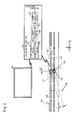
- FIG. 1 to FIG. 4 A first embodiment according to the present invention will be described with reference to FIG. 1 to FIG. 4 .
- the encoder 100 includes a scale 102, a detection head 110, a calculation portion 120 (first and second calculation device) and a display unit (display device) 130.
- the scale 102 and the detection head 110 are in a state of being separated from each other and are assembled on chosen machinery or equipment such that they maintain a predetermined mutual positional relationship to each other, in which the scale 102 and the detection head 110 are positioned closely to each other to the extent that they are brought into close contact with each other.
- the calculation portion 120 may be housed inside the detection head 110.
- the scale 102 is a reflection scale as shown in FIG. 1 , for example, and is provided in the measurement axis direction with an INC track 104, which operates as a main track, and an ABS track 106, which operates as an angle detection track arranged in parallel with the INC track 104.
- a light and dark pattern is cyclically formed along the measurement axis direction of the INC track 104 over the entire scale 102.
- a light and dark pattern is irregularly formed along the measurement axis direction of the ABS track 106 over the entire scale 102 (the main track and the angle detection track may both be INC tracks or may both be ABS tracks).
- a gap d between the INC track 104 and the ABS track 106 is set to be identical to a gap between an INC detection portion 112, which operates as a main detection portion, and an ABS detection portion 114, which operates as an auxiliary detection portion. Both the INC detection portion 112 and the ABS detection portion 114 are described below.
- the detection head 110 can be relatively displaced with respect to the scale 102 in the measurement axis direction.
- the detection head 110 includes the INC detection portion 112 that reads the INC track 104 and the ABS detection portion 114 that reads the ABS track 106, which are integrally provided thereto.
- the gap between the INC detection portion 112 and the ABS detection portion 114 is set to be identical to the gap d between the INC track 104 and the ABS track 106.
- the calculation portion 120 can perform various calculations with respect to outputs from the INC detection portion 112 and the ABS detection portion 114. More specifically, the calculation portion 120 can obtain a position of the INC track 104 Xinc and a position of the ABS track 106 Xabs that are detected by the INC detection portion 112 and ABS detection portion 114, respectively. Then, as shown in Formula (1), as first calculation device 121, the calculation portion 120 can obtain a yaw angle ⁇ .
- the calculation portion 120 can obtain a signal strength I based on two-phase sine wave signals Am and Bm that are output signals from the INC detection portion 112. Note that a relationship between the two-phase sine wave signals Am and Bm and the signal strength I can be shown as a Lissajous figure, as shown in FIG. 2 . Further, the output signals are not limited to the two-phase sine wave signals Am and Bm.
- the calculation portion 120 can output a relationship between the yaw angle ⁇ and the signal strength I corresponding to the yaw angle ⁇ , namely, a dependency of the signal strength I on the yaw angle to be displayed on the display unit 130.
- the display unit 130 can display an output of the calculation portion 120 as an image. More specifically, as shown in FIGs. 3A and 3B , for example, the display unit 130 sequentially displays a result output from the calculation portion 120 as a point on a coordinate having the yaw angle ⁇ on the horizontal axis and the signal strength I on the vertical axis. In other words, the display unit 130 can display relationships between a plurality of the yaw angles ⁇ and the signal strengths I corresponding to the respective yaw angles ⁇ , the plurality of the yaw angles ⁇ being output from the calculation portion 120. (In FIGs.
- a black circle shows the signal strength I at a present time and an outlined circle (white point) shows the signal strength I in the past up to the present time.
- the solid arrow shows a rotation direction of the detection head 110.
- the yaw angle ⁇ that shows a maximum signal strength Imax, at which the signal strength I reaches its maximum value, is identified as an optimum yaw angle ⁇ opt, and with the optimum yaw angle ⁇ opt, the detection head 110 is in a state of substantially having no inclination with respect to the scale 102.
- an initial yaw angle ⁇ is determined (step S2) by arranging the detection head 110 in a state of being clearly inclined with respect to the scale 102. Then, based on the outputs from the INC detection portion 112 and the ABS detection portion 114 of the detection head 110, the calculation portion 120 performs a calculation to obtain the difference amount ⁇ between the position Xinc of the INC track 104 and the position Xabs of the ABS track 106 (step S4).
- the calculation portion 120 performs a calculation to obtain the yaw angle ⁇ of the detection head 110 with respect to the measurement axis direction of the scale 102 (step S6). Then, the calculation portion 120 performs a calculation to obtain the signal strength I based on the two-phase sine wave signals Am and Bm that are output from the INC detection portion 112 (step S8). Then, the calculation portion 120 outputs, to the display unit 130, the relationship between the yaw angle ⁇ and the signal strength I corresponding to the yaw angle ⁇ .
- the display unit 130 displays the signal strength I corresponding to the yaw angle ⁇ as a point (step S10). Then, a comparison between the signal strength I based on the yaw angle ⁇ obtained this time and a signal strength Ip based on a yaw angle ⁇ p obtained a previous time is performed. If the signal strength I obtained this time is larger than the signal strength Ip obtained the previous time, it is determined that the optimum yaw angle ⁇ opt has not yet been passed (NO at step S12) and the yaw angle ⁇ is changed (step S14) (note that if the signal strength I is obtained for the first time, as the previous signal strength Ip is 0, the processing advances to step S14).
- a direction of the change is the same as a direction applied when the yaw angle ⁇ p of the previous time is changed to the yaw angle ⁇ obtained this time.
- the direction to change the yaw angle ⁇ is substantially a direction that makes the initial inclination of the detection head 110 become apparently smaller.
- the processing from step S4 to step S12 is repeated. More specifically, as shown in FIG. 3A , the signal strengths I obtained up to the previous time are displayed as points on the display unit 130 by the calculation portion 120, based on the change of the yaw angle ⁇ .
- the signal strength I reaches the maximum signal strength Imax, and then, the signal strength I becomes smaller than the maximum signal strength Imax.
- the signal strength I obtained this time becomes smaller than the signal strength Ip obtained the previous time and it is determined that the yaw angle ⁇ has passed the optimum yaw angle ⁇ opt (YES at step S12) (a state shown in FIG. 3A ).
- step S16 a display state of the plurality of points on the coordinates shown in FIG. 3A is checked on the display unit 130, the yaw angle ⁇ of the detection head 110 is changed in the opposite direction, and the yaw angle ⁇ is adjusted to the optimum yaw angle ⁇ opt, as shown in FIG. 3B (step S16).
- the yaw angle ⁇ is calculated using the difference between the position Xinc of the INC track 104 and the position Xabs of the ABS track 106. Therefore, even if the detection head 110 moves in the measurement axis direction while the yaw angle ⁇ of the detection head 110 is being changed, any impact on the yaw angle ⁇ is inhibited.
- step S12, step S14 and step S16 are performed by an operator.
- the present invention is not limited thereto.
- the present invention may be configured as in a second embodiment shown in FIG. 5 .
- a calculation portion 220 also operates as first calculation device 221 and second calculation device 222, in the same manner as in the first embodiment. More specifically, the calculation portion 220 calculates the signal strength I sequentially as the yaw angle ⁇ actually changes within a range including the optimum yaw angle ⁇ opt and displays a result of the calculation sequentially on a display unit 230, as shown in FIGs. 6A and 6B . At that time, the calculation portion 220 operates as fourth calculation device 224 and obtains the optimum yaw angle ⁇ opt based on changes in the signal strength I corresponding to a plurality of yaw angles ⁇ that are the results of the sequential calculation.
- the calculation portion 220 can recognize a current yaw angle ⁇ with respect to the optimum yaw angle ⁇ opt and calculate a rotational direction as a guide signal that guides the yaw angle ⁇ to the optimum yaw angle ⁇ opt. Then, based on the calculation result, as output device, the display unit 230 can display (output) the rotational direction (shown in FIGs. 6A and 6B as an outlined white arrow).
- constituent elements of the second embodiment other than the above-described ones are the same as those of the first embodiment, any description for those other structural elements is omitted herein.
- the optimum yaw angle ⁇ opt is obtained by calculating the signal strength I sequentially as the yaw angle ⁇ actually changes in the range including the optimum yaw angle ⁇ opt.
- the optimum yaw angle ⁇ opt quantitatively and to display the rotational direction of a detection head 210 toward the optimum yaw angle ⁇ opt on the display unit 230 (as shown in FIGs. 6A and 6B as the outlined white arrow). In this manner, it becomes possible to adjust the yaw angle ⁇ without using an oscilloscope, etc. and further to adjust the yaw angle ⁇ automatically.
- the rotational direction of the detection head 210 toward the optimum yaw angle ⁇ opt is displayed on the display unit 230 in the present embodiment
- a sound may be added thereto as a guide signal, and at that time, the rotational direction need not necessarily be displayed on the display unit.
- a rotational angle itself may be displayed on the display unit.
- guidance may be provided by outputting a sound only.
- the present invention may be configured as in a third embodiment shown in FIG. 7 .
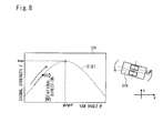
- a calculation portion 320 can obtain the optimum yaw angle ⁇ opt based on the changes in the signal strength I (that are obtained by the above-described fitted function) corresponding to a plurality of yaw angle ⁇ . More specifically, as shown in FIG.
- a function that passes through the plurality of points namely, a signal strength I( ⁇ )that is shown as a dashed line in FIG. 8
- the fitted function may be a multidimensional function or a trigonometric function, for example (other functions may also be fitted).
- coefficients a1 and b1 shown in Formula (3) are obtained by the least squares method while using three or more coordinates (note that c1 is also a coefficient).
- the optimum yaw angle ⁇ opt can be obtained as shown in Formula (5).
- the symbol I ⁇ represents I( ⁇ )in Formula (5). Further, a cumulative number of the symbol ⁇ is equivalent to the number of the plurality of points.
- a coefficient k shown in Formula (6) is obtained by the least squares method (note that a2 and b2 are also coefficients). Then, the optimum yaw angle ⁇ opt can be obtained as shown in Formula (7). In this case, it is possible to obtain the optimum yaw angle ⁇ opt faster as a result of being able to reduce an amount of calculation required to obtain the optimum yaw angle ⁇ opt in comparison with a case in which a multidimensional function is fitted.
- the symbol I represents I( ⁇ )in Formula (7).
- a cumulative number of the symbol ⁇ is equivalent to a number of the plurality of points.
- the third embodiment it is not necessary to actually change the yaw angle ⁇ within the range including the optimum yaw angle ⁇ opt, and changes in the signal strength I are obtained by fitting the function I( ⁇ ) while using a plurality of actual changes in the yaw angle ⁇ .
- the more points of the signal strength I that are actually calculated the more it is possible to accurately obtain the optimum yaw angle ⁇ opt on the function I( ⁇ ) that indicates the signal strength I.
- a sound may be added thereto as a guide signal, and at that time, the rotational direction need not necessarily be displayed on a display unit.
- a rotational angle itself may be displayed on the display unit. Further, even without having any display unit (display device) as output device, guidance may be provided by outputting a sound only.
- calculation portion functions as the first to fourth calculation device in the above-described embodiments
- the first to fourth calculation device may function separately instead of being integrated as the calculation portion.
- the separate linear encoder 100 is a reflection photoelectric linear encoder in the above-described embodiments, as shown in FIG. 1 , the present invention is not limited thereto.
- the separate linear encoder 100 may be a transmission photoelectric linear encoder.
- the separate linear encoder 100 may be one of encoders having other types of detection methods such as a magnetic encoder or a capacitance encoder having a periodic electrode pattern and an electromagnetic induction encoder having a periodic coil pattern.
- the present invention is a separate linear encoder that is assembled in machinery or equipment to be measured in a state in which a scale and a detection head are separately provided.
- the present invention can be widely applied to such encoders as a photoelectric encoder, a magnetic encoder, a capacitance encoder and an electromagnetic induction encoder.
Landscapes
- Physics & Mathematics (AREA)
- General Physics & Mathematics (AREA)
- Transmission And Conversion Of Sensor Element Output (AREA)
Applications Claiming Priority (1)
| Application Number | Priority Date | Filing Date | Title |
|---|---|---|---|
| JP2013022735A JP6285633B2 (ja) | 2013-02-07 | 2013-02-07 | セパレート式エンコーダ |
Publications (3)
| Publication Number | Publication Date |
|---|---|
| EP2765393A2 true EP2765393A2 (de) | 2014-08-13 |
| EP2765393A3 EP2765393A3 (de) | 2015-11-18 |
| EP2765393B1 EP2765393B1 (de) | 2016-09-21 |
Family
ID=50023472
Family Applications (1)
| Application Number | Title | Priority Date | Filing Date |
|---|---|---|---|
| EP14153431.3A Active EP2765393B1 (de) | 2013-02-07 | 2014-01-31 | Separater linearer Codierer |
Country Status (3)
| Country | Link |
|---|---|
| US (1) | US9175986B2 (de) |
| EP (1) | EP2765393B1 (de) |
| JP (1) | JP6285633B2 (de) |
Families Citing this family (2)
| Publication number | Priority date | Publication date | Assignee | Title |
|---|---|---|---|---|
| JP7391527B2 (ja) * | 2019-04-03 | 2023-12-05 | 株式会社ミツトヨ | 光電式エンコーダ |
| US12504301B2 (en) | 2023-09-21 | 2025-12-23 | Mitutoyo Corporation | Inductive linear encoder with gap adjustment |
Citations (1)
| Publication number | Priority date | Publication date | Assignee | Title |
|---|---|---|---|---|
| JP2010048786A (ja) | 2008-08-25 | 2010-03-04 | Mitsutoyo Corp | 外部調整型エンコーダ |
Family Cites Families (17)
| Publication number | Priority date | Publication date | Assignee | Title |
|---|---|---|---|---|
| WO1991003712A1 (en) * | 1989-09-06 | 1991-03-21 | Human Machine Interfaces Ltd. | Measurement device |
| US5442172A (en) * | 1994-05-27 | 1995-08-15 | International Business Machines Corporation | Wavefront reconstruction optics for use in a disk drive position measurement system |
| JP3795646B2 (ja) * | 1997-10-24 | 2006-07-12 | 株式会社ミツトヨ | 位置測定装置 |
| JP2001249001A (ja) * | 2000-03-03 | 2001-09-14 | Mitsutoyo Corp | 静電容量式変位検出装置 |
| DE10018298B4 (de) * | 2000-04-13 | 2012-04-05 | Dr. Johannes Heidenhain Gmbh | Verfahren und Vorrichtung zur Schwingungsdetektion bei einer Positionsmeßeinrichtung |
| US6690159B2 (en) * | 2000-09-28 | 2004-02-10 | Eldec Corporation | Position indicating system |
| JP2005127728A (ja) * | 2003-10-21 | 2005-05-19 | Kinichi Ogawa | 位置検出装置の取付け状態診断表示方法 |
| JP2006026990A (ja) * | 2004-07-14 | 2006-02-02 | Canon Finetech Inc | インクジェット記録装置 |
| JP2006194720A (ja) * | 2005-01-13 | 2006-07-27 | Mitsutoyo Corp | セパレート型エンコーダ、及び、その取付方法 |
| DE102006029650B4 (de) * | 2006-06-28 | 2020-02-20 | Dr. Johannes Heidenhain Gmbh | Schaltungsanordung und Verfahren zur Kippfehlerermittlung an einer Positionsmesseinrichtung |
| JP4783698B2 (ja) * | 2006-09-05 | 2011-09-28 | 株式会社ミツトヨ | 電磁誘導式エンコーダ |
| JP2009020041A (ja) * | 2007-07-13 | 2009-01-29 | Hiwin Mikrosystem Corp | 読取ヘッド用取付位置センサー |
| JP5073603B2 (ja) * | 2008-07-24 | 2012-11-14 | 株式会社ミツトヨ | アブソリュート型リニアエンコーダ、及び、その位置調整方法 |
| JP2011033368A (ja) * | 2009-07-30 | 2011-02-17 | Mitsutoyo Corp | 光学式エンコーダ |
| JP5601876B2 (ja) * | 2010-05-07 | 2014-10-08 | 株式会社ミツトヨ | セパレート型エンコーダ、及び、その取付方法 |
| US8866495B2 (en) * | 2010-06-30 | 2014-10-21 | Access Business Group International Llc | Spatial tracking system and method |
| JP5660671B2 (ja) * | 2011-01-07 | 2015-01-28 | ハイデンハイン株式会社 | エンコーダの信号処理装置 |
-
2013
- 2013-02-07 JP JP2013022735A patent/JP6285633B2/ja active Active
-
2014
- 2014-01-31 EP EP14153431.3A patent/EP2765393B1/de active Active
- 2014-02-05 US US14/173,227 patent/US9175986B2/en active Active
Patent Citations (1)
| Publication number | Priority date | Publication date | Assignee | Title |
|---|---|---|---|---|
| JP2010048786A (ja) | 2008-08-25 | 2010-03-04 | Mitsutoyo Corp | 外部調整型エンコーダ |
Also Published As
| Publication number | Publication date |
|---|---|
| EP2765393B1 (de) | 2016-09-21 |
| US20140217271A1 (en) | 2014-08-07 |
| JP2014153175A (ja) | 2014-08-25 |
| JP6285633B2 (ja) | 2018-02-28 |
| EP2765393A3 (de) | 2015-11-18 |
| US9175986B2 (en) | 2015-11-03 |
Similar Documents
| Publication | Publication Date | Title |
|---|---|---|
| EP3278079B1 (de) | Registrierung von gemessenen interferometrischen glasfaserdaten mit interferometrischen referenzglasfaserdaten | |
| EP2587224B1 (de) | Verschiebungserkennungsvorrichtung, Skalakalibrierverfahren und Skalakalibrierprogramm | |
| US9766054B2 (en) | Planar motor rotor displacement measuring device and its measuring method | |
| DE102018219146B4 (de) | Magnetfeldsensorsystem und verfahren zur positionserfassung | |
| EP4276407A2 (de) | Drahtseilmessvorrichtung und drahtseilmessverfahren | |
| EP3611476A1 (de) | Positionserkennungsvorrichtung und positionserkennungsverfahren | |
| JP6308739B2 (ja) | 位置検出装置及びそれを有するレンズ装置、画像読取装置及び画像形成装置 | |
| CN107167166A (zh) | 在干涉型传感系统中运动补偿的方法及装置 | |
| KR20120113653A (ko) | 간섭을 이용한 막 두께 계측 장치 및 간섭을 이용한 막 두께 계측 방법 | |
| EP2365291B1 (de) | Fotoelektrischer Kodierer | |
| US11940303B2 (en) | Position detection device and position detection method | |
| KR101135733B1 (ko) | 자극 위치 검출 장치 및 방법 | |
| US10119841B2 (en) | Magnetic position detection device and magnetic position detection method | |
| EP2765393B1 (de) | Separater linearer Codierer | |
| EP2420796A1 (de) | Verfahren und Vorrichtung zur Formmessung mittels Weisslichtinterferometrie | |
| US8708497B2 (en) | Three dimensional measurement apparatus and three dimensional measurement method | |
| US7748251B2 (en) | Circuit configuration and method for ascertaining tilt errors in connection with a position-measuring device | |
| JP6227875B2 (ja) | 位置測定装置で複数の走査検知ユニットを有する構造 | |
| EP3093624B1 (de) | Selbstkalibrierender lvdt-transformator-demodulator | |
| EP3021095B1 (de) | Spektroskopiesystem mit verschiebungsausgleich und spektroskopieverfahren mit dem spektroskopiesystem | |
| US11573103B2 (en) | Angle detector | |
| US10190893B2 (en) | Encoder | |
| RU2584577C1 (ru) | Способ калибровки магнитострикционных преобразователей линейных перемещений и устройство его реализации | |
| EP2650654B1 (de) | Codierer | |
| CN104236606B (zh) | 基准信号发生装置和基准信号发生系统 |
Legal Events
| Date | Code | Title | Description |
|---|---|---|---|
| PUAI | Public reference made under article 153(3) epc to a published international application that has entered the european phase |
Free format text: ORIGINAL CODE: 0009012 |
|
| 17P | Request for examination filed |
Effective date: 20140131 |
|
| AK | Designated contracting states |
Kind code of ref document: A2 Designated state(s): AL AT BE BG CH CY CZ DE DK EE ES FI FR GB GR HR HU IE IS IT LI LT LU LV MC MK MT NL NO PL PT RO RS SE SI SK SM TR |
|
| AX | Request for extension of the european patent |
Extension state: BA ME |
|
| PUAL | Search report despatched |
Free format text: ORIGINAL CODE: 0009013 |
|
| AK | Designated contracting states |
Kind code of ref document: A3 Designated state(s): AL AT BE BG CH CY CZ DE DK EE ES FI FR GB GR HR HU IE IS IT LI LT LU LV MC MK MT NL NO PL PT RO RS SE SI SK SM TR |
|
| AX | Request for extension of the european patent |
Extension state: BA ME |
|
| RIC1 | Information provided on ipc code assigned before grant |
Ipc: G01D 5/244 20060101AFI20151015BHEP Ipc: G01D 5/347 20060101ALI20151015BHEP Ipc: G01D 18/00 20060101ALI20151015BHEP |
|
| R17P | Request for examination filed (corrected) |
Effective date: 20151104 |
|
| RBV | Designated contracting states (corrected) |
Designated state(s): AL AT BE BG CH CY CZ DE DK EE ES FI FR GB GR HR HU IE IS IT LI LT LU LV MC MK MT NL NO PL PT RO RS SE SI SK SM TR |
|
| GRAP | Despatch of communication of intention to grant a patent |
Free format text: ORIGINAL CODE: EPIDOSNIGR1 |
|
| RIC1 | Information provided on ipc code assigned before grant |
Ipc: G01D 18/00 20060101ALI20160210BHEP Ipc: G01D 5/244 20060101AFI20160210BHEP Ipc: G01D 5/347 20060101ALI20160210BHEP |
|
| INTG | Intention to grant announced |
Effective date: 20160309 |
|
| GRAS | Grant fee paid |
Free format text: ORIGINAL CODE: EPIDOSNIGR3 |
|
| RAP1 | Party data changed (applicant data changed or rights of an application transferred) |
Owner name: MITUTOYO CORPORATION |
|
| GRAA | (expected) grant |
Free format text: ORIGINAL CODE: 0009210 |
|
| AK | Designated contracting states |
Kind code of ref document: B1 Designated state(s): AL AT BE BG CH CY CZ DE DK EE ES FI FR GB GR HR HU IE IS IT LI LT LU LV MC MK MT NL NO PL PT RO RS SE SI SK SM TR |
|
| REG | Reference to a national code |
Ref country code: GB Ref legal event code: FG4D |
|
| REG | Reference to a national code |
Ref country code: CH Ref legal event code: EP |
|
| REG | Reference to a national code |
Ref country code: AT Ref legal event code: REF Ref document number: 831416 Country of ref document: AT Kind code of ref document: T Effective date: 20161015 |
|
| REG | Reference to a national code |
Ref country code: IE Ref legal event code: FG4D |
|
| REG | Reference to a national code |
Ref country code: DE Ref legal event code: R096 Ref document number: 602014003704 Country of ref document: DE |
|
| REG | Reference to a national code |
Ref country code: LT Ref legal event code: MG4D Ref country code: NL Ref legal event code: MP Effective date: 20160921 |
|
| PG25 | Lapsed in a contracting state [announced via postgrant information from national office to epo] |
Ref country code: LT Free format text: LAPSE BECAUSE OF FAILURE TO SUBMIT A TRANSLATION OF THE DESCRIPTION OR TO PAY THE FEE WITHIN THE PRESCRIBED TIME-LIMIT Effective date: 20160921 Ref country code: RS Free format text: LAPSE BECAUSE OF FAILURE TO SUBMIT A TRANSLATION OF THE DESCRIPTION OR TO PAY THE FEE WITHIN THE PRESCRIBED TIME-LIMIT Effective date: 20160921 Ref country code: FI Free format text: LAPSE BECAUSE OF FAILURE TO SUBMIT A TRANSLATION OF THE DESCRIPTION OR TO PAY THE FEE WITHIN THE PRESCRIBED TIME-LIMIT Effective date: 20160921 Ref country code: NO Free format text: LAPSE BECAUSE OF FAILURE TO SUBMIT A TRANSLATION OF THE DESCRIPTION OR TO PAY THE FEE WITHIN THE PRESCRIBED TIME-LIMIT Effective date: 20161221 |
|
| REG | Reference to a national code |
Ref country code: AT Ref legal event code: MK05 Ref document number: 831416 Country of ref document: AT Kind code of ref document: T Effective date: 20160921 |
|
| PG25 | Lapsed in a contracting state [announced via postgrant information from national office to epo] |
Ref country code: SE Free format text: LAPSE BECAUSE OF FAILURE TO SUBMIT A TRANSLATION OF THE DESCRIPTION OR TO PAY THE FEE WITHIN THE PRESCRIBED TIME-LIMIT Effective date: 20160921 Ref country code: LV Free format text: LAPSE BECAUSE OF FAILURE TO SUBMIT A TRANSLATION OF THE DESCRIPTION OR TO PAY THE FEE WITHIN THE PRESCRIBED TIME-LIMIT Effective date: 20160921 Ref country code: GR Free format text: LAPSE BECAUSE OF FAILURE TO SUBMIT A TRANSLATION OF THE DESCRIPTION OR TO PAY THE FEE WITHIN THE PRESCRIBED TIME-LIMIT Effective date: 20161222 Ref country code: NL Free format text: LAPSE BECAUSE OF FAILURE TO SUBMIT A TRANSLATION OF THE DESCRIPTION OR TO PAY THE FEE WITHIN THE PRESCRIBED TIME-LIMIT Effective date: 20160921 |
|
| PG25 | Lapsed in a contracting state [announced via postgrant information from national office to epo] |
Ref country code: RO Free format text: LAPSE BECAUSE OF FAILURE TO SUBMIT A TRANSLATION OF THE DESCRIPTION OR TO PAY THE FEE WITHIN THE PRESCRIBED TIME-LIMIT Effective date: 20160921 Ref country code: EE Free format text: LAPSE BECAUSE OF FAILURE TO SUBMIT A TRANSLATION OF THE DESCRIPTION OR TO PAY THE FEE WITHIN THE PRESCRIBED TIME-LIMIT Effective date: 20160921 |
|
| PG25 | Lapsed in a contracting state [announced via postgrant information from national office to epo] |
Ref country code: ES Free format text: LAPSE BECAUSE OF FAILURE TO SUBMIT A TRANSLATION OF THE DESCRIPTION OR TO PAY THE FEE WITHIN THE PRESCRIBED TIME-LIMIT Effective date: 20160921 Ref country code: SK Free format text: LAPSE BECAUSE OF FAILURE TO SUBMIT A TRANSLATION OF THE DESCRIPTION OR TO PAY THE FEE WITHIN THE PRESCRIBED TIME-LIMIT Effective date: 20160921 Ref country code: PL Free format text: LAPSE BECAUSE OF FAILURE TO SUBMIT A TRANSLATION OF THE DESCRIPTION OR TO PAY THE FEE WITHIN THE PRESCRIBED TIME-LIMIT Effective date: 20160921 Ref country code: SM Free format text: LAPSE BECAUSE OF FAILURE TO SUBMIT A TRANSLATION OF THE DESCRIPTION OR TO PAY THE FEE WITHIN THE PRESCRIBED TIME-LIMIT Effective date: 20160921 Ref country code: CZ Free format text: LAPSE BECAUSE OF FAILURE TO SUBMIT A TRANSLATION OF THE DESCRIPTION OR TO PAY THE FEE WITHIN THE PRESCRIBED TIME-LIMIT Effective date: 20160921 Ref country code: AT Free format text: LAPSE BECAUSE OF FAILURE TO SUBMIT A TRANSLATION OF THE DESCRIPTION OR TO PAY THE FEE WITHIN THE PRESCRIBED TIME-LIMIT Effective date: 20160921 Ref country code: BG Free format text: LAPSE BECAUSE OF FAILURE TO SUBMIT A TRANSLATION OF THE DESCRIPTION OR TO PAY THE FEE WITHIN THE PRESCRIBED TIME-LIMIT Effective date: 20161221 Ref country code: BE Free format text: LAPSE BECAUSE OF FAILURE TO SUBMIT A TRANSLATION OF THE DESCRIPTION OR TO PAY THE FEE WITHIN THE PRESCRIBED TIME-LIMIT Effective date: 20160921 Ref country code: IS Free format text: LAPSE BECAUSE OF FAILURE TO SUBMIT A TRANSLATION OF THE DESCRIPTION OR TO PAY THE FEE WITHIN THE PRESCRIBED TIME-LIMIT Effective date: 20170121 Ref country code: PT Free format text: LAPSE BECAUSE OF FAILURE TO SUBMIT A TRANSLATION OF THE DESCRIPTION OR TO PAY THE FEE WITHIN THE PRESCRIBED TIME-LIMIT Effective date: 20170123 |
|
| REG | Reference to a national code |
Ref country code: DE Ref legal event code: R097 Ref document number: 602014003704 Country of ref document: DE |
|
| PG25 | Lapsed in a contracting state [announced via postgrant information from national office to epo] |
Ref country code: IT Free format text: LAPSE BECAUSE OF FAILURE TO SUBMIT A TRANSLATION OF THE DESCRIPTION OR TO PAY THE FEE WITHIN THE PRESCRIBED TIME-LIMIT Effective date: 20160921 |
|
| PLBE | No opposition filed within time limit |
Free format text: ORIGINAL CODE: 0009261 |
|
| STAA | Information on the status of an ep patent application or granted ep patent |
Free format text: STATUS: NO OPPOSITION FILED WITHIN TIME LIMIT |
|
| PG25 | Lapsed in a contracting state [announced via postgrant information from national office to epo] |
Ref country code: DK Free format text: LAPSE BECAUSE OF FAILURE TO SUBMIT A TRANSLATION OF THE DESCRIPTION OR TO PAY THE FEE WITHIN THE PRESCRIBED TIME-LIMIT Effective date: 20160921 |
|
| 26N | No opposition filed |
Effective date: 20170622 |
|
| REG | Reference to a national code |
Ref country code: CH Ref legal event code: PL |
|
| PG25 | Lapsed in a contracting state [announced via postgrant information from national office to epo] |
Ref country code: MC Free format text: LAPSE BECAUSE OF FAILURE TO SUBMIT A TRANSLATION OF THE DESCRIPTION OR TO PAY THE FEE WITHIN THE PRESCRIBED TIME-LIMIT Effective date: 20160921 |
|
| REG | Reference to a national code |
Ref country code: FR Ref legal event code: ST Effective date: 20170929 |
|
| PG25 | Lapsed in a contracting state [announced via postgrant information from national office to epo] |
Ref country code: CH Free format text: LAPSE BECAUSE OF NON-PAYMENT OF DUE FEES Effective date: 20170131 Ref country code: LI Free format text: LAPSE BECAUSE OF NON-PAYMENT OF DUE FEES Effective date: 20170131 Ref country code: FR Free format text: LAPSE BECAUSE OF NON-PAYMENT OF DUE FEES Effective date: 20170131 |
|
| REG | Reference to a national code |
Ref country code: IE Ref legal event code: MM4A |
|
| PG25 | Lapsed in a contracting state [announced via postgrant information from national office to epo] |
Ref country code: SI Free format text: LAPSE BECAUSE OF FAILURE TO SUBMIT A TRANSLATION OF THE DESCRIPTION OR TO PAY THE FEE WITHIN THE PRESCRIBED TIME-LIMIT Effective date: 20160921 Ref country code: LU Free format text: LAPSE BECAUSE OF NON-PAYMENT OF DUE FEES Effective date: 20170131 |
|
| PG25 | Lapsed in a contracting state [announced via postgrant information from national office to epo] |
Ref country code: IE Free format text: LAPSE BECAUSE OF NON-PAYMENT OF DUE FEES Effective date: 20170131 |
|
| PG25 | Lapsed in a contracting state [announced via postgrant information from national office to epo] |
Ref country code: MT Free format text: LAPSE BECAUSE OF NON-PAYMENT OF DUE FEES Effective date: 20170131 |
|
| PG25 | Lapsed in a contracting state [announced via postgrant information from national office to epo] |
Ref country code: AL Free format text: LAPSE BECAUSE OF FAILURE TO SUBMIT A TRANSLATION OF THE DESCRIPTION OR TO PAY THE FEE WITHIN THE PRESCRIBED TIME-LIMIT Effective date: 20160921 |
|
| PG25 | Lapsed in a contracting state [announced via postgrant information from national office to epo] |
Ref country code: HU Free format text: LAPSE BECAUSE OF FAILURE TO SUBMIT A TRANSLATION OF THE DESCRIPTION OR TO PAY THE FEE WITHIN THE PRESCRIBED TIME-LIMIT; INVALID AB INITIO Effective date: 20140131 |
|
| PG25 | Lapsed in a contracting state [announced via postgrant information from national office to epo] |
Ref country code: CY Free format text: LAPSE BECAUSE OF NON-PAYMENT OF DUE FEES Effective date: 20160921 |
|
| PG25 | Lapsed in a contracting state [announced via postgrant information from national office to epo] |
Ref country code: MK Free format text: LAPSE BECAUSE OF FAILURE TO SUBMIT A TRANSLATION OF THE DESCRIPTION OR TO PAY THE FEE WITHIN THE PRESCRIBED TIME-LIMIT Effective date: 20160921 |
|
| PG25 | Lapsed in a contracting state [announced via postgrant information from national office to epo] |
Ref country code: TR Free format text: LAPSE BECAUSE OF FAILURE TO SUBMIT A TRANSLATION OF THE DESCRIPTION OR TO PAY THE FEE WITHIN THE PRESCRIBED TIME-LIMIT Effective date: 20160921 |
|
| PG25 | Lapsed in a contracting state [announced via postgrant information from national office to epo] |
Ref country code: HR Free format text: LAPSE BECAUSE OF FAILURE TO SUBMIT A TRANSLATION OF THE DESCRIPTION OR TO PAY THE FEE WITHIN THE PRESCRIBED TIME-LIMIT Effective date: 20160921 |
|
| PGFP | Annual fee paid to national office [announced via postgrant information from national office to epo] |
Ref country code: GB Payment date: 20260123 Year of fee payment: 13 |
|
| PGFP | Annual fee paid to national office [announced via postgrant information from national office to epo] |
Ref country code: DE Payment date: 20260121 Year of fee payment: 13 |