EP2765247A1 - A siphonic flushing device - Google Patents
A siphonic flushing device Download PDFInfo
- Publication number
- EP2765247A1 EP2765247A1 EP14154130.0A EP14154130A EP2765247A1 EP 2765247 A1 EP2765247 A1 EP 2765247A1 EP 14154130 A EP14154130 A EP 14154130A EP 2765247 A1 EP2765247 A1 EP 2765247A1
- Authority
- EP
- European Patent Office
- Prior art keywords
- air
- flushing
- tube
- inlet
- flush
- Prior art date
- Legal status (The legal status is an assumption and is not a legal conclusion. Google has not performed a legal analysis and makes no representation as to the accuracy of the status listed.)
- Granted
Links
Images


Classifications
-
- E—FIXED CONSTRUCTIONS
- E03—WATER SUPPLY; SEWERAGE
- E03D—WATER-CLOSETS OR URINALS WITH FLUSHING DEVICES; FLUSHING VALVES THEREFOR
- E03D1/00—Water flushing devices with cisterns ; Setting up a range of flushing devices or water-closets; Combinations of several flushing devices
- E03D1/02—High-level flushing systems
- E03D1/06—Cisterns with tube siphons
- E03D1/12—Siphon action initiated by outlet of air
- E03D1/125—Siphon action initiated by outlet of air in cisterns with tube siphons
-
- E—FIXED CONSTRUCTIONS
- E03—WATER SUPPLY; SEWERAGE
- E03D—WATER-CLOSETS OR URINALS WITH FLUSHING DEVICES; FLUSHING VALVES THEREFOR
- E03D1/00—Water flushing devices with cisterns ; Setting up a range of flushing devices or water-closets; Combinations of several flushing devices
- E03D1/02—High-level flushing systems
- E03D1/14—Cisterns discharging variable quantities of water also cisterns with bell siphons in combination with flushing valves
- E03D1/141—Cisterns discharging variable quantities of water also cisterns with bell siphons in combination with flushing valves in cisterns with tube siphons and with tube siphons in combination with flushing valves
-
- E—FIXED CONSTRUCTIONS
- E03—WATER SUPPLY; SEWERAGE
- E03D—WATER-CLOSETS OR URINALS WITH FLUSHING DEVICES; FLUSHING VALVES THEREFOR
- E03D5/00—Special constructions of flushing devices, e.g. closed flushing system
- E03D5/02—Special constructions of flushing devices, e.g. closed flushing system operated mechanically or hydraulically (or pneumatically) also details such as push buttons, levers and pull-card therefor
- E03D5/024—Operated hydraulically or pneumatically
-
- E—FIXED CONSTRUCTIONS
- E03—WATER SUPPLY; SEWERAGE
- E03D—WATER-CLOSETS OR URINALS WITH FLUSHING DEVICES; FLUSHING VALVES THEREFOR
- E03D5/00—Special constructions of flushing devices, e.g. closed flushing system
- E03D5/02—Special constructions of flushing devices, e.g. closed flushing system operated mechanically or hydraulically (or pneumatically) also details such as push buttons, levers and pull-card therefor
- E03D5/09—Special constructions of flushing devices, e.g. closed flushing system operated mechanically or hydraulically (or pneumatically) also details such as push buttons, levers and pull-card therefor directly by the hand
Definitions
- the present invention relates to a siphonic flushing device. More particularly, the present invention relates to a dual flush siphonic flushing device, as well as to a toilet including such flushing device.
- Siphonic flushing devices have been available on the market for many years. Operating on the general principle of a siphon, such flushing device generally consists of a tubular bend being submerged into water enclosed within a water cistern.
- Double siphons include a tube being bent to form an M-shape. Hence, a water trap is formed between the inlet and the outlet such that air may be compressed between the inlet and the water trap.
- the siphon will draw water from the cistern until the water level of the cistern is below the inlet.
- an inlet valve After flushing an inlet valve will open for refilling the cistern. As the water level of the cistern rises, water will also start to fill the tube of the flushing device. As the vent valve is now closed, air will be compressed within the bend. Filling of water is finished when a specific water level is reached, whereby a subsequent flushing sequence may again be initiated.
- a siphonic flushing device provides a number of advantages compared to other flushing devices since there is no need for a moveable outlet valve.
- different solutions on the market still have some major drawbacks, especially when it comes to siphonic flushing devices having dual-flush capabilities, i.e. configurations allowing for small and large volume flushes.
- EP1640515 describes a double flush siphon flushing system.
- a vent valve allows compressed air to escape whereby the flushing sequence is performed.
- venting is controlled such that different volumes of water are discharged.
- this system provides a dual flush functionality.
- a number of disadvantages are associated with this kind of solution. As an example, it does not allow the flush volumes to be easily changed.
- a cistern divider is provided for changing the large volume flush from 6 liters to 9 liters; however no adjustment between these values is possible.
- this particular solution may not fit different markets having different standards for flushing volumes.
- the present invention seeks to mitigate or eliminate the above-identified deficiencies and solves at least the above mentioned problems by providing a siphonic flushing device with a dual flush functionality.
- An idea of the present invention is to provide a siphonic flushing device having an air intake device in connection with the siphon tube such that air intake may be controlled for terminating the flushing sequence at a specific flushing volume.
- a siphonic dual flushing device comprising a tube extending from an open inlet end to an open outlet end via a bend, arranged above said inlet end and said outlet end, as well as via a water trap formed between said bend and said outlet end, and wherein said outlet end is arranged below said inlet end; and an air intake device having an air outlet connected to said tube for allowing air to enter said tube for terminating an ongoing flush, wherein said air intake device further comprises a first air inlet arranged vertically below said air outlet, and a second air inlet arranged vertically below said first air inlet, and wherein a first flush volume is provided if air is introduced through the first inlet, and a second flush volume is provided if air is introduced through the second inlet.
- the air outlet of said air intake device may preferably be connected to said bend.
- a sub-pressure will be present during flushing due to the flow of water. Since air is introduced in the air inlet as the water level within the cistern lowers, flushing will always be terminated as air will be drawn into the bend due to the sub-pressure.
- the first air inlet of said air intake device may comprise a float valve being moveable in a vertical direction, which is advantageous in that the air inlet will open as soon as the water lever inside the cistern lowers to a predetermined level, set by the float valve.
- the air intake device may comprise a second air inlet arranged below said first air inlet.
- the volume of a large flush may be controlled such that a large volume flush not necessarily must correspond to the water level inside the cistern being lowered below the tube inlet end.
- undesired sound such as bubbling noise is reduced. This is due to the fact that the second air inlet, having a diameter substantially less than the diameter of the tube inlet, will provide smaller air bubbles entering the tube at a higher level.
- the second air inlet may comprise an open conduit end having an oblique cut. This further decreases unwanted noise associated with introducing air into the tube.
- the vertical position of said air intake device may be adjustable relative the tube, which is advantageous in that the volumes corresponding to large and small flushes may be easily adjusted.
- a first flushing volume may thus be achieved when the first air inlet is opened, and a second flushing volume being larger than the first flushing volume may thus be achieved when the first air inlet is locked in a closed position such that air is introduced via the second air inlet.
- the venting device may be connected to flush initiating means such that said venting device opens when a user operates said flush initiating means. Hence, immediate flushing is provided as soon as the user requests such action.
- the flush initiating means may preferably comprise two different push buttons, or rocker buttons or lift buttons, mechanically connected to said venting device.
- the flush initiating means may be mechanically connected to said air intake device, which is advantageous in that the choice of push button may control activation of the first air inlet.
- the first air inlet of the second venting device may be locked in a closed position when a user initiates a flushing sequence of a first volume, such that flushing is terminated when the water level outside the tube is below the vertical lever of the second air inlet of the air intake device.
- first air inlet of the second venting device may be released from said closed position when a user initiates a flushing sequence of a second volume being smaller than said first volume, such that flushing is terminated when the water level outside the tube is below the vertical lever of the first air inlet of the air intake device.
- a water cistern enclosing a siphonic flushing device according to the first aspect.
- a WC suite comprising a water cistern according to the second aspect.
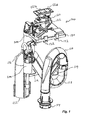
- the flushing device 100 generally includes a hollow tube 110, a venting device 200, as well as an air intake device 300. Additional components preferred for a proper functionality includes a flush initiating means 120 and a support structure 130 for fixation of the flush initiating means 120 and possibly also an inlet valve.
- the entire flushing device 100 is intended to be arranged inside a water cistern, such that water enclosed in the cistern may be flushed into an associated toilet bowl by means of the flushing device 100.
- the hollow tube 110 forms a water conduit extending from an open inlet 112 to an open outlet 114.
- the tube 110 extends vertically upwards from the inlet 112 to a bend 116 from which the tube 110 extends downwards to a second bend forming a water trap 118.
- the tube 110 has an M-shape.
- the tube 110 is preferably twisted around the vertical axis as is shown in Fig. 1 .
- the tube 110 is manufactured as two or more parts which may be easily connected by a snap-lock, threads, or similar. Further, ribs 119 may be provided for increasing the stability of the tube 110 and arranged to connect different portions of the outer surface of the tube 110. However the tube 110 may also be manufactured by welding two or more parts together or it may be formed as one part by means of blow molding technology.
- the outlet 114 is connected to an inlet port of a WC bowl (not shown).
- the outlet 114 is arranged vertically below the inlet 112.
- the flushing device 100 is configured to be arranged within a water cistern (not shown), e.g. a separate cistern, on a WC suite, or enclosed within the back rest of a WC bowl or enclosed within a wall supporting a wall hung WC.
- a water cistern e.g. a separate cistern
- the support structure 130 has portions 132 for engagement with corresponding fastening portions of the cistern.
- the flushing device 100 is aligned within the cistern such that the outlet 114 of the tube connects with inlet port to the WC bowl. In such position, the inlet 112 of the tube 110 is arranged at a certain vertical distance from the bottom of the cistern such that water present in the cistern may flow through the inlet 112.
- water is enclosed within the cistern up to a predefined level.
- the predefined water level corresponding to a full cistern, is arranged above the bend 116.
- the water trap 118 also accommodates water from a prior flush, such that air is entrapped between the bend 116 and the water trap 118. Since the water within the tube 110 (i.e. water coming from the inlet 112) has forced the air within the tube 110 to move towards the bend and the water trap 118, this air is compressed.
- a venting device 200 is configured to release the air entrapped within the bend 116 such that the pressure is reduced, whereby cistern water will start to flow into the tube 110 and over the bend 116, into the water trap 118, and subsequently out trough the outlet 114.
- Flushing is aborted when the water level in the cistern is below the inlet 112 of the tube 110, or when air is again introduced into the tube 110. Upon this, an inlet valve will open whereby the cistern is again filled with water returning the flushing system to a state where it is ready to begin flushing.
- a venting device 200 is preferably mechanically linked to the flush initiating means 120.
- the flush initiating means 120 may e.g. include two push buttons 121a, 121b, which when pressed down provides a small volume flush or a large volume flush, respectively. It should however be appreciated that the push buttons may be replaced by rocker buttons or lift buttons, providing the same functionality of activating flushing sequences of different water volumes.
- a tilting of a lever construction 122 When one of the buttons 121a, 121b is pressed down a tilting of a lever construction 122 will cause a release action on the venting device 200 such that it opens, thus allowing air compressed within the bend 116 to escape. Releasing the air will thus create a sub-pressure within the tube 110 which will draw water from the inlet 112, over the bend 116, and out through the outlet 114. That is, releasing air will start flushing.
- the lever construction 122 locks the venting device 200 in a closed position thus preventing it from open and from releasing entrapped air.
- the push buttons 121a, 121b are preferably accessible from the outside of the water cistern such that they are readily available for a user.
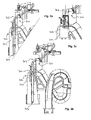
- Figs. 2a-c side views and cross sectional views of the venting device 200 are shown.
- the venting device is arranged at the bend 116 and includes a fluid connection 202 at the highest position of the tube 110.
- the fluid connection 202 extends upwards as a hollow conduit 204 which is surrounded by a hollow housing 206 being sealed against the outer surface of the tube 110.
- the hollow housing 206 forms an annular volume 207 delimited by the hollow conduit 204. During cistern filling, this annular volume 207 is at least partly filled with water.
- the hollow conduit 204 has an open upper end 208 which may be sealed against a piston 210 being moveable and engagable by a respective motion of the lever construction 122.
- the piston having a cylindrical shape with a closed upper end, extends into the water of the annular volume 207 thus forming a water trap preventing air inside the tube 110 to escape.
- Fig. 2b a zoomed-in view of the venting device 200 is shown.
- the piston 210 is thus pressed down such that the sidewall of the piston 210 extends into the water of the annular volume 207. Air inside the bend 116 may thus not escape, whereby flushing is prevented.
- the lever construction 122 will unlock the piston 210 whereby the compressed air will be able to force the piston 210 upwards to allow escape. This is shown in Fig.
- the lever construction 122 is preferably spring biased towards it idle position such that the piston 210 will automatically return to the position where the piston 210 is submerged into the water of the annular volume 207 and blocked from moving upwards. Hence, the piston 210 forms an open-ended cylinder.
- venting device 200 provides a mechanical connection between the flush initiating means 120 and the tube 110, such that upon initiating a flush, the venting device 200 unlocks the piston 210 whereby the compressed air inside the bend 116 is allowed to escape, thereby starting the flushing.
- the venting device 200 operates in the same manner independently of a large or small flush.
- the air intake device 300 is arranged outside the tube 110 and has an air outlet connected to the tube 110 at the bend 116 at a position close to the venting device connection 202 (shown in Fig. 2a ).
- the air intake device 300 is connected to the tube 110 via a flexible hose 302 (see e.g. Fig. 5b ) such that the vertical position of the air intake device 300 relative the tube 110 may be easily adjusted.
- some sort of fastener such as a guiding rod, may be provided along the outer surface of the tube 110 to which the air intake device 300 may be attached at different vertical positions.
- the air intake device 300 includes two separate air inlets 304, 306 arranged at different vertical positions.
- the air inlets 304, 306 are provided such that the first inlet 304 will be opened when a small volume flush is initiated, whereby the second air inlet 306 is operational when a large volume flush is initiated.
- Fig. 3a the air intake device 300 is shown where a large volume flush is activated.
- a mechanical link 310 connected to the lever construction 122 will cause a mechanical locking action on the air intake device, as shown in Fig. 3c .
- a float valve 320 also shown in Fig. 3c ) associated with the first air inlet 304 will be locked in its position thus keeping the first air inlet 304 closed.
- the locking action may preferably be provided by a protrusion on the air intake device 300 being engagable with a recess of the mechanical link 310 such that when the mechanical link 310 is in a first position, the recess prevents the float 320 of the air intake device 300 from moving downwards.
- the mechanical link 310 moves corresponding to a small volume flush, the recess will no longer engage the protrusion of the air intake device such that the float 320 of the air intake device 300 is free to move downwards.
- the water level inside the cistern will lower until it goes below the vertical position of the second air inlet 306. Hence, air will be allowed to flow into the bend 116 whereby flushing is terminated.
- the air intake device 300 operates by allowing or preventing a float 320 from moving with the water level inside the cistern.
- a large volume flush is initiated the float 320 is locked in an upright position whereby the upper air inlet 304 is closed. Even when the water level inside the cistern lowers during flushing, the float 320 will remain in its upper position thus keeping the air inlet 304 closed.
- a small volume flush is initiated the float will no longer be locked due to a different movement of the mechanical link 310 (please note that the venting device 200 is always actuated independently of large or small volume flush initiation).
- the float 320 will move correspondingly, thus exposing the air inlet 304 when the water level is below the vertical position of the air inlet 304.
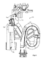
- Fig. 4 the flushing device 100 is shown wherein a small volume flush is initiated.
- the mechanical link 310 will release the float valve 320 of the air intake device 300 at the same time as the venting device 200 is maneuvered, i.e. when the flush starts.
- the float valve 320 will also move downwards.
- the movement of the float valve 320 will open the first air inlet 304 such that air will be allowed to enter the bend 116 for terminating the flushing sequence.
- the float valve 320 may include a floating body 322 being slidable on a vertical venting tube 324.
- the floating body 322 which is released upon initiating a small volume flush, will move downwards along with the water level during flushing due to gravity. As the floating body 322 lowers, it will eventually allow air to enter the vertical venting tube 324 (see Fig. 5b ).
- a valve seat 326 is provided on the upper part of the vertical venting tube 324 adjacent to and connected to the flexible hose 302.
- the valve seat 326 has tapered surfaces 328 engagable with corresponding tapered surfaces 330 on the inner side of the floating body 322.
- a small slit preferably annular, is provided between the vertical venting tube 324 and the valve seat 326 for allowing air flow into the valve seat 326, as indicated by the arrow in Fig. 5b .
- flushing will be terminated as air is allowed to enter the vertical venting tube 324 and escapes upwards into the bend 116 via the valve seat 326 and the flexible hose 302.
- the floating body 322 will move upwards and again seal the holes in the vertical tube 324.
- the second air inlet 306 may preferably be provided with an oblique cut, which has been proven to reduce undesired sound when air is introduced for terminating the flushing sequence. As previously described, reduced diameter of the air intake pipe will reduce the size of air bubbles thus reducing the generated sound. The second air inlet 306 is operational only when the float 320 is locked, i.e. when initiating a large volume flush.
- the air intake device 300 thus provides a highly advantageous construction for allowing two different volumes of flushing.
- the floating body 322 is locked or unlocked depending on the last flush initiating being either one of the buttons 121a, 121b, A new flush initiation will directly cause a corresponding action on the floating body, i.e. causing it to be locked or unlocked.
- the present invention may be used for WC bowls suspended from a wall structure as well as WC bowls securely attached to the floor; or separate flushing cisterns arranged inside or outside a wall.
- Vertical flushing buttons providing mechanical activation of the flushing will only requiring minor modifications for connecting the manual flush buttons with the venting device and the air intake device.
- all references to "upper”, “lower”, “above”, “below”, “upwards, downwards”, or similar should be interpreted as a position during normal use, i.e. when the flushing device is mounted in a water cistern.
Landscapes
- Health & Medical Sciences (AREA)
- Life Sciences & Earth Sciences (AREA)
- Engineering & Computer Science (AREA)
- Hydrology & Water Resources (AREA)
- Public Health (AREA)
- Water Supply & Treatment (AREA)
- Sanitary Device For Flush Toilet (AREA)
Abstract
Description
- The present invention relates to a siphonic flushing device. More particularly, the present invention relates to a dual flush siphonic flushing device, as well as to a toilet including such flushing device.
- Siphonic flushing devices have been available on the market for many years. Operating on the general principle of a siphon, such flushing device generally consists of a tubular bend being submerged into water enclosed within a water cistern.
- For a siphon action of a flushing device having only one upper bend, water inside the tube is normally mechanically forced upwards to start a flow of water through the bend. However, as significant force is necessary for actually moving the required quantity of water upwards double siphons have been suggested.
- Double siphons include a tube being bent to form an M-shape. Hence, a water trap is formed between the inlet and the outlet such that air may be compressed between the inlet and the water trap.
- Prior to flushing, i.e. in the phase of filling the cistern with water compressed air will be entrapped within the first bend, thus being arranged at the highest vertical position of the tube and preventing water from flowing through the bend.
- Upon flushing the air is allowed to escape through a vent valve whereby the water inside the tube is allowed to flow over the bend and further into the WC bowl. As the outlet is arranged vertically below the inlet, i.e. the open tubular end arranged within the cistern, the siphon will draw water from the cistern until the water level of the cistern is below the inlet.
- After flushing an inlet valve will open for refilling the cistern. As the water level of the cistern rises, water will also start to fill the tube of the flushing device. As the vent valve is now closed, air will be compressed within the bend. Filling of water is finished when a specific water level is reached, whereby a subsequent flushing sequence may again be initiated.
- A siphonic flushing device provides a number of advantages compared to other flushing devices since there is no need for a moveable outlet valve. However, different solutions on the market still have some major drawbacks, especially when it comes to siphonic flushing devices having dual-flush capabilities, i.e. configurations allowing for small and large volume flushes.
- For example,
EP1640515 describes a double flush siphon flushing system. Similarly to the general description above, a vent valve allows compressed air to escape whereby the flushing sequence is performed. By providing two different push buttons corresponding to large or small flush volume, venting is controlled such that different volumes of water are discharged. Hence, this system provides a dual flush functionality. However, a number of disadvantages are associated with this kind of solution. As an example, it does not allow the flush volumes to be easily changed. A cistern divider is provided for changing the large volume flush from 6 liters to 9 liters; however no adjustment between these values is possible. Hence, this particular solution may not fit different markets having different standards for flushing volumes. - It would therefore be advantageous to provide a more versatile flushing device which allows for easy adjustment of the flushing volume in order to fit various needs on the market.
- The present invention seeks to mitigate or eliminate the above-identified deficiencies and solves at least the above mentioned problems by providing a siphonic flushing device with a dual flush functionality.
- An idea of the present invention is to provide a siphonic flushing device having an air intake device in connection with the siphon tube such that air intake may be controlled for terminating the flushing sequence at a specific flushing volume.
- According to a first aspect, a siphonic flushing device is provided. The flushing device comprises a tube extending from an open inlet end to an open outlet end via a bend, arranged above said inlet end and said outlet end, as well as via a water trap formed between said bend and said outlet end , and wherein said outlet end is arranged vertically below said inlet end; and a venting device connected to said bend for allowing air entrapped within said bend to escape; wherein said flushing device further comprises an air intake device having an air outlet connected to said tube for allowing air to enter said tube, wherein said air intake device further comprises a first air inlet arranged vertically below said air outlet.
- According to another aspect, a siphonic dual flushing device is provided. The device comprises a tube extending from an open inlet end to an open outlet end via a bend, arranged above said inlet end and said outlet end, as well as via a water trap formed between said bend and said outlet end, and wherein said outlet end is arranged below said inlet end; and an air intake device having an air outlet connected to said tube for allowing air to enter said tube for terminating an ongoing flush, wherein said air intake device further comprises a first air inlet arranged vertically below said air outlet, and a second air inlet arranged vertically below said first air inlet, and wherein a first flush volume is provided if air is introduced through the first inlet, and a second flush volume is provided if air is introduced through the second inlet.
- The air outlet of said air intake device may preferably be connected to said bend. Inside the tube, a sub-pressure will be present during flushing due to the flow of water. Since air is introduced in the air inlet as the water level within the cistern lowers, flushing will always be terminated as air will be drawn into the bend due to the sub-pressure.
- The first air inlet of said air intake device may comprise a float valve being moveable in a vertical direction, which is advantageous in that the air inlet will open as soon as the water lever inside the cistern lowers to a predetermined level, set by the float valve.
- The air intake device may comprise a second air inlet arranged below said first air inlet. Hence, the volume of a large flush may be controlled such that a large volume flush not necessarily must correspond to the water level inside the cistern being lowered below the tube inlet end. Further, by terminating a large volume flush by introducing air into the bend via the second air inlet, undesired sound, such as bubbling noise is reduced. This is due to the fact that the second air inlet, having a diameter substantially less than the diameter of the tube inlet, will provide smaller air bubbles entering the tube at a higher level.
- The second air inlet may comprise an open conduit end having an oblique cut. This further decreases unwanted noise associated with introducing air into the tube.
- The vertical position of said air intake device may be adjustable relative the tube, which is advantageous in that the volumes corresponding to large and small flushes may be easily adjusted.
- A first flushing volume may thus be achieved when the first air inlet is opened, and a second flushing volume being larger than the first flushing volume may thus be achieved when the first air inlet is locked in a closed position such that air is introduced via the second air inlet.
- The venting device may be connected to flush initiating means such that said venting device opens when a user operates said flush initiating means. Hence, immediate flushing is provided as soon as the user requests such action.
- The flush initiating means may preferably comprise two different push buttons, or rocker buttons or lift buttons, mechanically connected to said venting device.
- The flush initiating means may be mechanically connected to said air intake device, which is advantageous in that the choice of push button may control activation of the first air inlet.
- The first air inlet of the second venting device may be locked in a closed position when a user initiates a flushing sequence of a first volume, such that flushing is terminated when the water level outside the tube is below the vertical lever of the second air inlet of the air intake device.
- Further, the first air inlet of the second venting device may be released from said closed position when a user initiates a flushing sequence of a second volume being smaller than said first volume, such that flushing is terminated when the water level outside the tube is below the vertical lever of the first air inlet of the air intake device.
- According to a second aspect, a water cistern is provided enclosing a siphonic flushing device according to the first aspect.
- According to a third aspect a WC suite is provided comprising a water cistern according to the second aspect.
- These and other aspects, features and advantages of which the invention is capable of will be apparent and elucidated from the following description of embodiments of the present invention, reference being made to the accompanying drawings, in which
-
Fig. 1 is an isometric view of a siphonic flushing device according to an embodiment; -
Fig. 2a is side view of the flushing device shown inFig.1 in an idle mode; -
Fig. 2b is a cross-sectional view of a venting device in a closed position; -
Fig. 2c is a cross-sectional view of the venting device in an open position; -
Fig. 3a is a cross-sectional view of a flushing device prior to initiating a flush sequence; -
Fig. 3b is a view of the flushing device ofFig. 3a upon initiating a large volume flush sequence; -
Fig. 3c is a side view of an air intake device of the flushing device; -
Fig. 4 is a side view of the flushing device ofFig. 3a upon initiating a small volume flush sequence; and -
Fig. 5a-b are side views of the flushing device ofFig. 4 after a small volume flushing water is discharged. - In the following, embodiments of a
siphonic flushing device 100 will be described. Starting withFig. 1 theflushing device 100 generally includes ahollow tube 110, aventing device 200, as well as anair intake device 300. Additional components preferred for a proper functionality includes a flush initiating means 120 and asupport structure 130 for fixation of the flush initiating means 120 and possibly also an inlet valve. - The
entire flushing device 100 is intended to be arranged inside a water cistern, such that water enclosed in the cistern may be flushed into an associated toilet bowl by means of theflushing device 100. - The
hollow tube 110 forms a water conduit extending from anopen inlet 112 to anopen outlet 114. Thetube 110 extends vertically upwards from theinlet 112 to abend 116 from which thetube 110 extends downwards to a second bend forming a water trap 118. Hence, thetube 110 has an M-shape. However, in order to reduce the lateral extension thetube 110 is preferably twisted around the vertical axis as is shown inFig. 1 . - Preferably, the
tube 110 is manufactured as two or more parts which may be easily connected by a snap-lock, threads, or similar. Further,ribs 119 may be provided for increasing the stability of thetube 110 and arranged to connect different portions of the outer surface of thetube 110. However thetube 110 may also be manufactured by welding two or more parts together or it may be formed as one part by means of blow molding technology. - As the
siphonic tube 110 is configured to draw flushing water from theinlet 112 to theoutlet 114, theoutlet 114 is connected to an inlet port of a WC bowl (not shown). Theoutlet 114 is arranged vertically below theinlet 112. - The
flushing device 100 is configured to be arranged within a water cistern (not shown), e.g. a separate cistern, on a WC suite, or enclosed within the back rest of a WC bowl or enclosed within a wall supporting a wall hung WC. For securely fastening the flushing device in the cistern thesupport structure 130 hasportions 132 for engagement with corresponding fastening portions of the cistern. Theflushing device 100 is aligned within the cistern such that theoutlet 114 of the tube connects with inlet port to the WC bowl. In such position, theinlet 112 of thetube 110 is arranged at a certain vertical distance from the bottom of the cistern such that water present in the cistern may flow through theinlet 112. - Before turning into details of the flush initiating means 120, the
venting device 200, and theair intake device 300, some details of the general functionality will be given. - Before a flush, water is enclosed within the cistern up to a predefined level. As the
inlet 112 of thetube 110 is always open water will also have entered thetube 110 up to the same level. The predefined water level, corresponding to a full cistern, is arranged above thebend 116. Hence, a small volume of water may flow into the water trap 118 until the pressure of the compressed air is preventing water to flow over thebend 116. The water trap 118 also accommodates water from a prior flush, such that air is entrapped between thebend 116 and the water trap 118. Since the water within the tube 110 (i.e. water coming from the inlet 112) has forced the air within thetube 110 to move towards the bend and the water trap 118, this air is compressed. - A
venting device 200 is configured to release the air entrapped within thebend 116 such that the pressure is reduced, whereby cistern water will start to flow into thetube 110 and over thebend 116, into the water trap 118, and subsequently out trough theoutlet 114. - Flushing is aborted when the water level in the cistern is below the
inlet 112 of thetube 110, or when air is again introduced into thetube 110. Upon this, an inlet valve will open whereby the cistern is again filled with water returning the flushing system to a state where it is ready to begin flushing. - Now turning to particular embodiments of a siphonic flushing device, a
venting device 200 is preferably mechanically linked to theflush initiating means 120. The flush initiating means 120 may e.g. include two push buttons 121a, 121b, which when pressed down provides a small volume flush or a large volume flush, respectively. It should however be appreciated that the push buttons may be replaced by rocker buttons or lift buttons, providing the same functionality of activating flushing sequences of different water volumes. - When one of the buttons 121a, 121b is pressed down a tilting of a
lever construction 122 will cause a release action on theventing device 200 such that it opens, thus allowing air compressed within thebend 116 to escape. Releasing the air will thus create a sub-pressure within thetube 110 which will draw water from theinlet 112, over thebend 116, and out through theoutlet 114. That is, releasing air will start flushing. - Correspondingly, when the buttons are resting in their idle position (i.e. not being pressed down) the
lever construction 122 locks theventing device 200 in a closed position thus preventing it from open and from releasing entrapped air. - The push buttons 121a, 121b are preferably accessible from the outside of the water cistern such that they are readily available for a user.
- Turning now to
Figs. 2a-c , side views and cross sectional views of theventing device 200 are shown. As can be seen inFig. 2a the venting device is arranged at thebend 116 and includes afluid connection 202 at the highest position of thetube 110. Thefluid connection 202 extends upwards as a hollow conduit 204 which is surrounded by ahollow housing 206 being sealed against the outer surface of thetube 110. Thehollow housing 206 forms anannular volume 207 delimited by the hollow conduit 204. During cistern filling, thisannular volume 207 is at least partly filled with water. - The hollow conduit 204 has an open
upper end 208 which may be sealed against apiston 210 being moveable and engagable by a respective motion of thelever construction 122. The piston, having a cylindrical shape with a closed upper end, extends into the water of theannular volume 207 thus forming a water trap preventing air inside thetube 110 to escape. - That is, when a user uses the flush initiating means 120 for starting a flush the
piston 210 will move in a vertically linear manner as will be further described below. - Turning now to
Fig. 2b , a zoomed-in view of theventing device 200 is shown. In this position, there is no movement of the push buttons 121a, 121b such that theventing device 200 is closed. As is clearly seen, thepiston 210 is thus pressed down such that the sidewall of thepiston 210 extends into the water of theannular volume 207. Air inside thebend 116 may thus not escape, whereby flushing is prevented. However, as soon as a user presses any one of the push buttons 121a, 121b, thelever construction 122 will unlock thepiston 210 whereby the compressed air will be able to force thepiston 210 upwards to allow escape. This is shown inFig. 2c , where thepiston 210 is raised by the air pressure inside thebend 116 such that the sidewall of thepiston 210 no longer extends into the water of theannular volume 207. Thelever construction 122 is preferably spring biased towards it idle position such that thepiston 210 will automatically return to the position where thepiston 210 is submerged into the water of theannular volume 207 and blocked from moving upwards. Hence, thepiston 210 forms an open-ended cylinder. - In accordance with the description so far the
venting device 200 provides a mechanical connection between the flush initiating means 120 and thetube 110, such that upon initiating a flush, theventing device 200 unlocks thepiston 210 whereby the compressed air inside thebend 116 is allowed to escape, thereby starting the flushing. Theventing device 200 operates in the same manner independently of a large or small flush. - Now turning to
Figs. 3a-c , details of theair intake device 300 will be discussed. Theair intake device 300 is arranged outside thetube 110 and has an air outlet connected to thetube 110 at thebend 116 at a position close to the venting device connection 202 (shown inFig. 2a ). Theair intake device 300 is connected to thetube 110 via a flexible hose 302 (see e.g.Fig. 5b ) such that the vertical position of theair intake device 300 relative thetube 110 may be easily adjusted. Further, some sort of fastener, such as a guiding rod, may be provided along the outer surface of thetube 110 to which theair intake device 300 may be attached at different vertical positions. Theair intake device 300 includes twoseparate air inlets first inlet 304 will be opened when a small volume flush is initiated, whereby thesecond air inlet 306 is operational when a large volume flush is initiated. - In
Fig. 3a , theair intake device 300 is shown where a large volume flush is activated. When the corresponding push button 121a is pressed down amechanical link 310 connected to thelever construction 122 will cause a mechanical locking action on the air intake device, as shown inFig. 3c . Hence, a float valve 320 (also shown inFig. 3c ) associated with thefirst air inlet 304 will be locked in its position thus keeping thefirst air inlet 304 closed. The locking action may preferably be provided by a protrusion on theair intake device 300 being engagable with a recess of themechanical link 310 such that when themechanical link 310 is in a first position, the recess prevents thefloat 320 of theair intake device 300 from moving downwards. Correspondingly, when themechanical link 310 moves corresponding to a small volume flush, the recess will no longer engage the protrusion of the air intake device such that thefloat 320 of theair intake device 300 is free to move downwards. As the flushing proceeds the water level inside the cistern will lower until it goes below the vertical position of thesecond air inlet 306. Hence, air will be allowed to flow into thebend 116 whereby flushing is terminated. - From above it is clear that the
air intake device 300 operates by allowing or preventing afloat 320 from moving with the water level inside the cistern. When a large volume flush is initiated thefloat 320 is locked in an upright position whereby theupper air inlet 304 is closed. Even when the water level inside the cistern lowers during flushing, thefloat 320 will remain in its upper position thus keeping theair inlet 304 closed. On the other hand, when a small volume flush is initiated the float will no longer be locked due to a different movement of the mechanical link 310 (please note that theventing device 200 is always actuated independently of large or small volume flush initiation). When the water level lowers thefloat 320 will move correspondingly, thus exposing theair inlet 304 when the water level is below the vertical position of theair inlet 304. - Now turning to
Fig. 4 , theflushing device 100 is shown wherein a small volume flush is initiated. When a user presses the corresponding push button 121b, themechanical link 310 will release thefloat valve 320 of theair intake device 300 at the same time as theventing device 200 is maneuvered, i.e. when the flush starts. Hence, when the water level of the cistern drops, thefloat valve 320 will also move downwards. Turning toFigs. 5a and 5b , the movement of thefloat valve 320 will open thefirst air inlet 304 such that air will be allowed to enter thebend 116 for terminating the flushing sequence. - As is readily understood, during flushing there will be no or very little air inside the
tube 110 since the air has escaped during initiating the flush. However, once air is allowed to enter thetube 110 at the position of thebend 116, flushing will be terminated since the suction force will dra air instead of water into thebend 116. Large and small volume flush is thus controlled by setting the water level at which theair intake device 300 introduces air into thetube 110, i.e. the water level of the cistern in which thetube 110 is arranged. - The
float valve 320 may include a floatingbody 322 being slidable on avertical venting tube 324. The floatingbody 322, which is released upon initiating a small volume flush, will move downwards along with the water level during flushing due to gravity. As the floatingbody 322 lowers, it will eventually allow air to enter the vertical venting tube 324 (seeFig. 5b ). For this, avalve seat 326 is provided on the upper part of thevertical venting tube 324 adjacent to and connected to theflexible hose 302. Thevalve seat 326 has taperedsurfaces 328 engagable with correspondingtapered surfaces 330 on the inner side of the floatingbody 322. A small slit, preferably annular, is provided between thevertical venting tube 324 and thevalve seat 326 for allowing air flow into thevalve seat 326, as indicated by the arrow inFig. 5b . Hence, flushing will be terminated as air is allowed to enter thevertical venting tube 324 and escapes upwards into thebend 116 via thevalve seat 326 and theflexible hose 302. When the water level in the cistern is raised upon filling, the floatingbody 322 will move upwards and again seal the holes in thevertical tube 324. - The
second air inlet 306 may preferably be provided with an oblique cut, which has been proven to reduce undesired sound when air is introduced for terminating the flushing sequence. As previously described, reduced diameter of the air intake pipe will reduce the size of air bubbles thus reducing the generated sound. Thesecond air inlet 306 is operational only when thefloat 320 is locked, i.e. when initiating a large volume flush. - The
air intake device 300 thus provides a highly advantageous construction for allowing two different volumes of flushing. The floatingbody 322 is locked or unlocked depending on the last flush initiating being either one of the buttons 121a, 121b, A new flush initiation will directly cause a corresponding action on the floating body, i.e. causing it to be locked or unlocked. - The present invention has been described above with reference to specific embodiments. However, other embodiments are equally possible within the scope of the invention. The invention is thus only limited by the appended claims.
- It is also to be understood that the present invention may be used for WC bowls suspended from a wall structure as well as WC bowls securely attached to the floor; or separate flushing cisterns arranged inside or outside a wall. Vertical flushing buttons providing mechanical activation of the flushing will only requiring minor modifications for connecting the manual flush buttons with the venting device and the air intake device. Further, all references to "upper", "lower", "above", "below", "upwards, downwards", or similar should be interpreted as a position during normal use, i.e. when the flushing device is mounted in a water cistern.
Claims (14)
- A siphonic dual flushing device, comprising
a tube (110) extending from an open inlet end (112) to an open outlet end (114) via a bend (116), arranged above said inlet end (112) and said outlet end (114), as well as via a water trap (118) formed between said bend (116) and said outlet end (114), and wherein said outlet end (114) is arranged below said inlet end (112); and
an air intake device (300) having an air outlet connected to said tube (110) for allowing air to enter said tube (110) for terminating an ongoing flush, wherein said air intake device (300) further comprises a first air inlet (304) arranged vertically below said air outlet, and a second air inlet (306) arranged vertically below said first air inlet (304), and wherein a first flush volume is provided if air is introduced through the first inlet (304), and a second flush volume is provided if air is introduced through the second inlet (306). - The siphonic flushing device according to claim 1, wherein the air outlet of said air intake device (300) is connected to said bend (116).
- The siphonic flushing device according to claim 1 or 2, wherein said first air inlet (304) of said air intake device (300) comprises a float valve being moveable in a vertical direction.
- The siphonic flushing device according to any one of the preceding claims, further comprising a venting device (200) connected to said bend (116) for allowing air entrapped within said bend (116) to escape for initiating a flush.
- The siphonic flushing device according to any one of the preceding claims, wherein said second air inlet (306) comprises an open conduit end having an oblique cut.
- The siphonic flushing device according to any one of the preceding claims, wherein the tube (110) comprises a support to which the air intake device (300) is connected such that the vertical position of said air intake device (300) is adjustable relative the tube (110).
- The siphonic flushing device according to any one of the preceding claims, wherein a first flushing volume is achieved when the first air inlet (304) is opened thus allowing air to flow into the tube (110), and a second flushing volume being larger than the first flushing volume is achieved when the first air inlet (304) is locked in a closed position such that air is introduced via the second air inlet (306) thus allowing air to flow into the tube (110).
- The siphonic flushing device according to any one of the preceding claims, wherein said venting device (200) is connected to flush initiating means (120) such that a piston (210) of said venting device (200) is unlocked and allowed to open when a user operates said flush initiating means (120).
- The siphonic flushing device according to claim 8, wherein said flush initiating means (120) comprises two different push buttons (121a, 121b) mechanically connected to the piston (210) of said venting device (200).
- The siphonic flushing device according to claim 8 or 9, wherein said flush initiating means (120) is mechanically connected to said air intake device (300).
- The siphonic flushing device according to claim 4, wherein said first air inlet (304) of the air intake device (300) is configured to be locked in a closed position when a user initiates a flushing sequence of a first volume, such that flushing is terminated when the water level outside the tube (110) is below the vertical level of the second air inlet (306) of the air intake device (300) whereby air is allowed to flow into the tube (110).
- The siphonic flushing device according to claim 11, wherein said first air inlet (304) of the air intake device (300) is configured to be released from said closed position when a user initiates a flushing sequence of a second volume being smaller than said first volume, such that flushing is terminated when the water level outside the tube (110) is below the vertical level of the first air inlet (304) of the air intake device (300) whereby air is allowed to flow into the tube (110).
- A water cistern, enclosing a siphonic flushing device according to any one the preceding claims.
- A WC suite, comprising a water cistern according to claim 13.
Applications Claiming Priority (1)
| Application Number | Priority Date | Filing Date | Title |
|---|---|---|---|
| SE1350144 | 2013-02-06 |
Publications (2)
| Publication Number | Publication Date |
|---|---|
| EP2765247A1 true EP2765247A1 (en) | 2014-08-13 |
| EP2765247B1 EP2765247B1 (en) | 2021-10-06 |
Family
ID=50064475
Family Applications (1)
| Application Number | Title | Priority Date | Filing Date |
|---|---|---|---|
| EP14154130.0A Active EP2765247B1 (en) | 2013-02-06 | 2014-02-06 | A siphonic flushing device |
Country Status (4)
| Country | Link |
|---|---|
| EP (1) | EP2765247B1 (en) |
| DK (1) | DK2765247T3 (en) |
| ES (1) | ES2899993T3 (en) |
| PT (1) | PT2765247T (en) |
Cited By (2)
| Publication number | Priority date | Publication date | Assignee | Title |
|---|---|---|---|---|
| JP2020192848A (en) * | 2019-05-27 | 2020-12-03 | 株式会社砂▲崎▼製作所 | Water sealing device for high-speed vehicle |
| WO2022016459A1 (en) * | 2020-07-23 | 2022-01-27 | 厦门恩沐智能科技有限公司 | Toilet flushing apparatus |
Families Citing this family (1)
| Publication number | Priority date | Publication date | Assignee | Title |
|---|---|---|---|---|
| GB2642212A (en) * | 2024-06-26 | 2026-01-07 | Cistermiser Ltd | A System Comprising a Flush Control Mechanism |
Citations (6)
| Publication number | Priority date | Publication date | Assignee | Title |
|---|---|---|---|---|
| US1604759A (en) * | 1925-11-17 | 1926-10-26 | Harold B Richards | Siphon |
| GB618980A (en) * | 1946-11-15 | 1949-03-02 | Eric Bayly | Improvements in syphonic flushing apparatus |
| AU437147B2 (en) * | 1968-03-18 | 1973-06-22 | Squair Corporation Limited | Siphon valve |
| GB2276640A (en) * | 1993-03-30 | 1994-10-05 | Alan David Somerfield | W.C. cistern |
| EP0794292A1 (en) * | 1993-06-22 | 1997-09-10 | Gösta Leopold Hammarstedt | An actuating mechanism for flushing systems for water closets |
| EP1640515A1 (en) | 2004-09-27 | 2006-03-29 | MEPA- Pauli und Menden GmbH | Cistern with additional air injector, and use of such a cistern |
-
2014
- 2014-02-06 DK DK14154130.0T patent/DK2765247T3/en active
- 2014-02-06 ES ES14154130T patent/ES2899993T3/en active Active
- 2014-02-06 EP EP14154130.0A patent/EP2765247B1/en active Active
- 2014-02-06 PT PT141541300T patent/PT2765247T/en unknown
Patent Citations (6)
| Publication number | Priority date | Publication date | Assignee | Title |
|---|---|---|---|---|
| US1604759A (en) * | 1925-11-17 | 1926-10-26 | Harold B Richards | Siphon |
| GB618980A (en) * | 1946-11-15 | 1949-03-02 | Eric Bayly | Improvements in syphonic flushing apparatus |
| AU437147B2 (en) * | 1968-03-18 | 1973-06-22 | Squair Corporation Limited | Siphon valve |
| GB2276640A (en) * | 1993-03-30 | 1994-10-05 | Alan David Somerfield | W.C. cistern |
| EP0794292A1 (en) * | 1993-06-22 | 1997-09-10 | Gösta Leopold Hammarstedt | An actuating mechanism for flushing systems for water closets |
| EP1640515A1 (en) | 2004-09-27 | 2006-03-29 | MEPA- Pauli und Menden GmbH | Cistern with additional air injector, and use of such a cistern |
Cited By (3)
| Publication number | Priority date | Publication date | Assignee | Title |
|---|---|---|---|---|
| JP2020192848A (en) * | 2019-05-27 | 2020-12-03 | 株式会社砂▲崎▼製作所 | Water sealing device for high-speed vehicle |
| JP7205899B2 (en) | 2019-05-27 | 2023-01-17 | 株式会社砂▲崎▼製作所 | Water sealing device for high-speed vehicles |
| WO2022016459A1 (en) * | 2020-07-23 | 2022-01-27 | 厦门恩沐智能科技有限公司 | Toilet flushing apparatus |
Also Published As
| Publication number | Publication date |
|---|---|
| DK2765247T3 (en) | 2021-12-20 |
| EP2765247B1 (en) | 2021-10-06 |
| ES2899993T3 (en) | 2022-03-15 |
| PT2765247T (en) | 2021-12-16 |
Similar Documents
| Publication | Publication Date | Title |
|---|---|---|
| US8701220B2 (en) | Jet powered toilet flushing system | |
| EP2321476B1 (en) | Cistern draining apparatus with movable siphon | |
| EA039580B1 (en) | Device for toilets | |
| EP2765247B1 (en) | A siphonic flushing device | |
| US6061844A (en) | Water-conserving toilet having independently flushable main and urinal bowls | |
| US6199221B1 (en) | Flush valve | |
| CN104619928A (en) | Toilet discharge valve assembly having moveable buoyant float therein | |
| CN101395419B (en) | Hydraulic control device | |
| US9151028B2 (en) | Flushing valve | |
| US4171547A (en) | Toilet-blow flush system and devices therefor | |
| US380854A (en) | boyle | |
| CN1073184C (en) | Filling and emptying devices for toilet flush cisterns | |
| US4128906A (en) | Toilet-bowl flush system and devices therefor | |
| US8117687B2 (en) | Diverter valve with minimum bias forces | |
| US2740129A (en) | Valve mechanism for flush tanks | |
| US5228144A (en) | Water saving device for toilets | |
| US12234629B2 (en) | Flush valve and toilet assembly | |
| EP1466223B1 (en) | Improved liquid level controller | |
| US542485A (en) | Valve for water-closets | |
| US20080005830A1 (en) | Dual Volume Flush System | |
| SE504888C2 (en) | Flushing system for WC chairs | |
| US2589265A (en) | Spud valve | |
| US2615173A (en) | Flushing cistern | |
| EP2803773A1 (en) | Toilet flushing system | |
| JP2008223357A (en) | Washing water supply device |
Legal Events
| Date | Code | Title | Description |
|---|---|---|---|
| PUAI | Public reference made under article 153(3) epc to a published international application that has entered the european phase |
Free format text: ORIGINAL CODE: 0009012 |
|
| 17P | Request for examination filed |
Effective date: 20140206 |
|
| AK | Designated contracting states |
Kind code of ref document: A1 Designated state(s): AL AT BE BG CH CY CZ DE DK EE ES FI FR GB GR HR HU IE IS IT LI LT LU LV MC MK MT NL NO PL PT RO RS SE SI SK SM TR |
|
| AX | Request for extension of the european patent |
Extension state: BA ME |
|
| R17P | Request for examination filed (corrected) |
Effective date: 20150213 |
|
| RBV | Designated contracting states (corrected) |
Designated state(s): AL AT BE BG CH CY CZ DE DK EE ES FI FR GB GR HR HU IE IS IT LI LT LU LV MC MK MT NL NO PL PT RO RS SE SI SK SM TR |
|
| RAP1 | Party data changed (applicant data changed or rights of an application transferred) |
Owner name: GEBERIT INTERNATIONAL AG |
|
| STAA | Information on the status of an ep patent application or granted ep patent |
Free format text: STATUS: EXAMINATION IS IN PROGRESS |
|
| 17Q | First examination report despatched |
Effective date: 20180702 |
|
| GRAP | Despatch of communication of intention to grant a patent |
Free format text: ORIGINAL CODE: EPIDOSNIGR1 |
|
| STAA | Information on the status of an ep patent application or granted ep patent |
Free format text: STATUS: GRANT OF PATENT IS INTENDED |
|
| INTG | Intention to grant announced |
Effective date: 20210519 |
|
| GRAS | Grant fee paid |
Free format text: ORIGINAL CODE: EPIDOSNIGR3 |
|
| GRAA | (expected) grant |
Free format text: ORIGINAL CODE: 0009210 |
|
| STAA | Information on the status of an ep patent application or granted ep patent |
Free format text: STATUS: THE PATENT HAS BEEN GRANTED |
|
| AK | Designated contracting states |
Kind code of ref document: B1 Designated state(s): AL AT BE BG CH CY CZ DE DK EE ES FI FR GB GR HR HU IE IS IT LI LT LU LV MC MK MT NL NO PL PT RO RS SE SI SK SM TR |
|
| REG | Reference to a national code |
Ref country code: GB Ref legal event code: FG4D |
|
| REG | Reference to a national code |
Ref country code: CH Ref legal event code: EP Ref country code: AT Ref legal event code: REF Ref document number: 1436356 Country of ref document: AT Kind code of ref document: T Effective date: 20211015 |
|
| REG | Reference to a national code |
Ref country code: IE Ref legal event code: FG4D |
|
| REG | Reference to a national code |
Ref country code: DE Ref legal event code: R096 Ref document number: 602014080474 Country of ref document: DE |
|
| REG | Reference to a national code |
Ref country code: FI Ref legal event code: FGE |
|
| REG | Reference to a national code |
Ref country code: PT Ref legal event code: SC4A Ref document number: 2765247 Country of ref document: PT Date of ref document: 20211216 Kind code of ref document: T Free format text: AVAILABILITY OF NATIONAL TRANSLATION Effective date: 20211209 |
|
| REG | Reference to a national code |
Ref country code: DK Ref legal event code: T3 Effective date: 20211216 |
|
| REG | Reference to a national code |
Ref country code: NL Ref legal event code: FP |
|
| REG | Reference to a national code |
Ref country code: LT Ref legal event code: MG9D Ref country code: SE Ref legal event code: TRGR |
|
| REG | Reference to a national code |
Ref country code: NO Ref legal event code: T2 Effective date: 20211006 |
|
| REG | Reference to a national code |
Ref country code: ES Ref legal event code: FG2A Ref document number: 2899993 Country of ref document: ES Kind code of ref document: T3 Effective date: 20220315 |
|
| PG25 | Lapsed in a contracting state [announced via postgrant information from national office to epo] |
Ref country code: RS Free format text: LAPSE BECAUSE OF FAILURE TO SUBMIT A TRANSLATION OF THE DESCRIPTION OR TO PAY THE FEE WITHIN THE PRESCRIBED TIME-LIMIT Effective date: 20211006 Ref country code: LT Free format text: LAPSE BECAUSE OF FAILURE TO SUBMIT A TRANSLATION OF THE DESCRIPTION OR TO PAY THE FEE WITHIN THE PRESCRIBED TIME-LIMIT Effective date: 20211006 Ref country code: BG Free format text: LAPSE BECAUSE OF FAILURE TO SUBMIT A TRANSLATION OF THE DESCRIPTION OR TO PAY THE FEE WITHIN THE PRESCRIBED TIME-LIMIT Effective date: 20220106 |
|
| PG25 | Lapsed in a contracting state [announced via postgrant information from national office to epo] |
Ref country code: IS Free format text: LAPSE BECAUSE OF FAILURE TO SUBMIT A TRANSLATION OF THE DESCRIPTION OR TO PAY THE FEE WITHIN THE PRESCRIBED TIME-LIMIT Effective date: 20220206 Ref country code: PL Free format text: LAPSE BECAUSE OF FAILURE TO SUBMIT A TRANSLATION OF THE DESCRIPTION OR TO PAY THE FEE WITHIN THE PRESCRIBED TIME-LIMIT Effective date: 20211006 Ref country code: LV Free format text: LAPSE BECAUSE OF FAILURE TO SUBMIT A TRANSLATION OF THE DESCRIPTION OR TO PAY THE FEE WITHIN THE PRESCRIBED TIME-LIMIT Effective date: 20211006 Ref country code: HR Free format text: LAPSE BECAUSE OF FAILURE TO SUBMIT A TRANSLATION OF THE DESCRIPTION OR TO PAY THE FEE WITHIN THE PRESCRIBED TIME-LIMIT Effective date: 20211006 Ref country code: GR Free format text: LAPSE BECAUSE OF FAILURE TO SUBMIT A TRANSLATION OF THE DESCRIPTION OR TO PAY THE FEE WITHIN THE PRESCRIBED TIME-LIMIT Effective date: 20220107 |
|
| REG | Reference to a national code |
Ref country code: DE Ref legal event code: R097 Ref document number: 602014080474 Country of ref document: DE |
|
| PG25 | Lapsed in a contracting state [announced via postgrant information from national office to epo] |
Ref country code: SM Free format text: LAPSE BECAUSE OF FAILURE TO SUBMIT A TRANSLATION OF THE DESCRIPTION OR TO PAY THE FEE WITHIN THE PRESCRIBED TIME-LIMIT Effective date: 20211006 Ref country code: SK Free format text: LAPSE BECAUSE OF FAILURE TO SUBMIT A TRANSLATION OF THE DESCRIPTION OR TO PAY THE FEE WITHIN THE PRESCRIBED TIME-LIMIT Effective date: 20211006 Ref country code: RO Free format text: LAPSE BECAUSE OF FAILURE TO SUBMIT A TRANSLATION OF THE DESCRIPTION OR TO PAY THE FEE WITHIN THE PRESCRIBED TIME-LIMIT Effective date: 20211006 Ref country code: EE Free format text: LAPSE BECAUSE OF FAILURE TO SUBMIT A TRANSLATION OF THE DESCRIPTION OR TO PAY THE FEE WITHIN THE PRESCRIBED TIME-LIMIT Effective date: 20211006 Ref country code: CZ Free format text: LAPSE BECAUSE OF FAILURE TO SUBMIT A TRANSLATION OF THE DESCRIPTION OR TO PAY THE FEE WITHIN THE PRESCRIBED TIME-LIMIT Effective date: 20211006 |
|
| PLBE | No opposition filed within time limit |
Free format text: ORIGINAL CODE: 0009261 |
|
| STAA | Information on the status of an ep patent application or granted ep patent |
Free format text: STATUS: NO OPPOSITION FILED WITHIN TIME LIMIT |
|
| 26N | No opposition filed |
Effective date: 20220707 |
|
| PG25 | Lapsed in a contracting state [announced via postgrant information from national office to epo] |
Ref country code: MC Free format text: LAPSE BECAUSE OF FAILURE TO SUBMIT A TRANSLATION OF THE DESCRIPTION OR TO PAY THE FEE WITHIN THE PRESCRIBED TIME-LIMIT Effective date: 20211006 |
|
| PG25 | Lapsed in a contracting state [announced via postgrant information from national office to epo] |
Ref country code: LU Free format text: LAPSE BECAUSE OF NON-PAYMENT OF DUE FEES Effective date: 20220206 Ref country code: AL Free format text: LAPSE BECAUSE OF FAILURE TO SUBMIT A TRANSLATION OF THE DESCRIPTION OR TO PAY THE FEE WITHIN THE PRESCRIBED TIME-LIMIT Effective date: 20211006 |
|
| REG | Reference to a national code |
Ref country code: AT Ref legal event code: UEP Ref document number: 1436356 Country of ref document: AT Kind code of ref document: T Effective date: 20211006 |
|
| PG25 | Lapsed in a contracting state [announced via postgrant information from national office to epo] |
Ref country code: SI Free format text: LAPSE BECAUSE OF FAILURE TO SUBMIT A TRANSLATION OF THE DESCRIPTION OR TO PAY THE FEE WITHIN THE PRESCRIBED TIME-LIMIT Effective date: 20211006 |
|
| PG25 | Lapsed in a contracting state [announced via postgrant information from national office to epo] |
Ref country code: IE Free format text: LAPSE BECAUSE OF NON-PAYMENT OF DUE FEES Effective date: 20220206 |
|
| P01 | Opt-out of the competence of the unified patent court (upc) registered |
Effective date: 20230527 |
|
| PG25 | Lapsed in a contracting state [announced via postgrant information from national office to epo] |
Ref country code: HU Free format text: LAPSE BECAUSE OF FAILURE TO SUBMIT A TRANSLATION OF THE DESCRIPTION OR TO PAY THE FEE WITHIN THE PRESCRIBED TIME-LIMIT; INVALID AB INITIO Effective date: 20140206 |
|
| PG25 | Lapsed in a contracting state [announced via postgrant information from national office to epo] |
Ref country code: MK Free format text: LAPSE BECAUSE OF FAILURE TO SUBMIT A TRANSLATION OF THE DESCRIPTION OR TO PAY THE FEE WITHIN THE PRESCRIBED TIME-LIMIT Effective date: 20211006 Ref country code: CY Free format text: LAPSE BECAUSE OF FAILURE TO SUBMIT A TRANSLATION OF THE DESCRIPTION OR TO PAY THE FEE WITHIN THE PRESCRIBED TIME-LIMIT Effective date: 20211006 |
|
| REG | Reference to a national code |
Ref country code: NL Ref legal event code: PD Owner name: GEBERIT HOLDING AG; CH Free format text: DETAILS ASSIGNMENT: CHANGE OF OWNER(S), MERGE; FORMER OWNER NAME: GEBERIT INTERNATIONAL AG Effective date: 20240604 Ref country code: NL Ref legal event code: HC Owner name: GEBERIT INTERNATIONAL AG; CH Free format text: DETAILS ASSIGNMENT: CHANGE OF OWNER(S), CHANGE OF OWNER(S) NAME; FORMER OWNER NAME: GEBERIT HOLDING AG Effective date: 20240604 |
|
| REG | Reference to a national code |
Ref country code: BE Ref legal event code: PD Owner name: GEBERIT HOLDING AG; CH Free format text: DETAILS ASSIGNMENT: CHANGE OF OWNER(S), MERGE; FORMER OWNER NAME: GEBERIT INTERNATIONAL AG Effective date: 20240528 Ref country code: BE Ref legal event code: HC Owner name: GEBERIT INTERNATIONAL AG; CH Free format text: DETAILS ASSIGNMENT: CHANGE OF OWNER(S), CHANGE OF OWNER(S) NAME; FORMER OWNER NAME: GEBERIT HOLDING AG Effective date: 20240528 |
|
| PG25 | Lapsed in a contracting state [announced via postgrant information from national office to epo] |
Ref country code: MT Free format text: LAPSE BECAUSE OF FAILURE TO SUBMIT A TRANSLATION OF THE DESCRIPTION OR TO PAY THE FEE WITHIN THE PRESCRIBED TIME-LIMIT Effective date: 20211006 |
|
| REG | Reference to a national code |
Ref country code: AT Ref legal event code: PC Ref document number: 1436356 Country of ref document: AT Kind code of ref document: T Owner name: GEBERIT INTERNATIONAL AG, CH Effective date: 20241118 |
|
| PG25 | Lapsed in a contracting state [announced via postgrant information from national office to epo] |
Ref country code: TR Free format text: LAPSE BECAUSE OF FAILURE TO SUBMIT A TRANSLATION OF THE DESCRIPTION OR TO PAY THE FEE WITHIN THE PRESCRIBED TIME-LIMIT Effective date: 20211006 |
|
| REG | Reference to a national code |
Ref country code: CH Ref legal event code: U11 Free format text: ST27 STATUS EVENT CODE: U-0-0-U10-U11 (AS PROVIDED BY THE NATIONAL OFFICE) Effective date: 20260301 |
|
| PGFP | Annual fee paid to national office [announced via postgrant information from national office to epo] |
Ref country code: NL Payment date: 20260210 Year of fee payment: 13 |
|
| PGFP | Annual fee paid to national office [announced via postgrant information from national office to epo] |
Ref country code: SE Payment date: 20260209 Year of fee payment: 13 |
|
| PGFP | Annual fee paid to national office [announced via postgrant information from national office to epo] |
Ref country code: GB Payment date: 20260210 Year of fee payment: 13 |
|
| PGFP | Annual fee paid to national office [announced via postgrant information from national office to epo] |
Ref country code: ES Payment date: 20260303 Year of fee payment: 13 |
|
| PGFP | Annual fee paid to national office [announced via postgrant information from national office to epo] |
Ref country code: NO Payment date: 20260212 Year of fee payment: 13 Ref country code: DK Payment date: 20260210 Year of fee payment: 13 Ref country code: DE Payment date: 20260211 Year of fee payment: 13 |
|
| PGFP | Annual fee paid to national office [announced via postgrant information from national office to epo] |
Ref country code: AT Payment date: 20260212 Year of fee payment: 13 |
|
| PGFP | Annual fee paid to national office [announced via postgrant information from national office to epo] |
Ref country code: BE Payment date: 20260203 Year of fee payment: 13 Ref country code: IT Payment date: 20260126 Year of fee payment: 13 Ref country code: FI Payment date: 20260205 Year of fee payment: 13 |
|
| PGFP | Annual fee paid to national office [announced via postgrant information from national office to epo] |
Ref country code: FR Payment date: 20260210 Year of fee payment: 13 |
|
| PGFP | Annual fee paid to national office [announced via postgrant information from national office to epo] |
Ref country code: PT Payment date: 20260202 Year of fee payment: 13 Ref country code: CH Payment date: 20260301 Year of fee payment: 13 |