EP2763156A1 - X-ray source with improved target lifetime - Google Patents
X-ray source with improved target lifetime Download PDFInfo
- Publication number
- EP2763156A1 EP2763156A1 EP13154072.6A EP13154072A EP2763156A1 EP 2763156 A1 EP2763156 A1 EP 2763156A1 EP 13154072 A EP13154072 A EP 13154072A EP 2763156 A1 EP2763156 A1 EP 2763156A1
- Authority
- EP
- European Patent Office
- Prior art keywords
- target
- electron beam
- steering means
- ray source
- focussing
- Prior art date
- Legal status (The legal status is an assumption and is not a legal conclusion. Google has not performed a legal analysis and makes no representation as to the accuracy of the status listed.)
- Withdrawn
Links
- 238000010894 electron beam technology Methods 0.000 claims abstract description 135
- 238000000034 method Methods 0.000 claims description 10
- 238000010521 absorption reaction Methods 0.000 claims description 3
- 238000007789 sealing Methods 0.000 claims description 3
- 238000005219 brazing Methods 0.000 claims description 2
- 229910052751 metal Inorganic materials 0.000 claims description 2
- 239000002184 metal Substances 0.000 claims description 2
- 229920001971 elastomer Polymers 0.000 abstract description 10
- 239000000806 elastomer Substances 0.000 abstract description 10
- 230000008901 benefit Effects 0.000 abstract description 3
- 230000008030 elimination Effects 0.000 abstract description 2
- 238000003379 elimination reaction Methods 0.000 abstract description 2
- 239000000463 material Substances 0.000 description 13
- 239000013077 target material Substances 0.000 description 9
- 239000000758 substrate Substances 0.000 description 7
- 239000007789 gas Substances 0.000 description 5
- 230000004075 alteration Effects 0.000 description 3
- 238000001454 recorded image Methods 0.000 description 3
- XEEYBQQBJWHFJM-UHFFFAOYSA-N Iron Chemical compound [Fe] XEEYBQQBJWHFJM-UHFFFAOYSA-N 0.000 description 2
- 230000015556 catabolic process Effects 0.000 description 2
- 230000008859 change Effects 0.000 description 2
- 238000006731 degradation reaction Methods 0.000 description 2
- 230000007613 environmental effect Effects 0.000 description 2
- 230000004907 flux Effects 0.000 description 2
- 238000003384 imaging method Methods 0.000 description 2
- 238000012804 iterative process Methods 0.000 description 2
- 238000012544 monitoring process Methods 0.000 description 2
- WFKWXMTUELFFGS-UHFFFAOYSA-N tungsten Chemical compound [W] WFKWXMTUELFFGS-UHFFFAOYSA-N 0.000 description 2
- 229910052721 tungsten Inorganic materials 0.000 description 2
- 239000010937 tungsten Substances 0.000 description 2
- 230000000007 visual effect Effects 0.000 description 2
- RYGMFSIKBFXOCR-UHFFFAOYSA-N Copper Chemical compound [Cu] RYGMFSIKBFXOCR-UHFFFAOYSA-N 0.000 description 1
- 108010083687 Ion Pumps Proteins 0.000 description 1
- ZOKXTWBITQBERF-UHFFFAOYSA-N Molybdenum Chemical compound [Mo] ZOKXTWBITQBERF-UHFFFAOYSA-N 0.000 description 1
- 229910000831 Steel Inorganic materials 0.000 description 1
- 239000004411 aluminium Substances 0.000 description 1
- 229910052782 aluminium Inorganic materials 0.000 description 1
- XAGFODPZIPBFFR-UHFFFAOYSA-N aluminium Chemical compound [Al] XAGFODPZIPBFFR-UHFFFAOYSA-N 0.000 description 1
- 229910052790 beryllium Inorganic materials 0.000 description 1
- ATBAMAFKBVZNFJ-UHFFFAOYSA-N beryllium atom Chemical compound [Be] ATBAMAFKBVZNFJ-UHFFFAOYSA-N 0.000 description 1
- 150000001875 compounds Chemical class 0.000 description 1
- 238000010276 construction Methods 0.000 description 1
- 229910052802 copper Inorganic materials 0.000 description 1
- 239000010949 copper Substances 0.000 description 1
- 230000001419 dependent effect Effects 0.000 description 1
- 229910003460 diamond Inorganic materials 0.000 description 1
- 239000010432 diamond Substances 0.000 description 1
- 230000000694 effects Effects 0.000 description 1
- 230000003993 interaction Effects 0.000 description 1
- 229910052742 iron Inorganic materials 0.000 description 1
- 238000005259 measurement Methods 0.000 description 1
- 229910052750 molybdenum Inorganic materials 0.000 description 1
- 239000011733 molybdenum Substances 0.000 description 1
- 230000000737 periodic effect Effects 0.000 description 1
- 239000012466 permeate Substances 0.000 description 1
- 230000008569 process Effects 0.000 description 1
- 239000010959 steel Substances 0.000 description 1
Images


Classifications
-
- H—ELECTRICITY
- H01—ELECTRIC ELEMENTS
- H01J—ELECTRIC DISCHARGE TUBES OR DISCHARGE LAMPS
- H01J35/00—X-ray tubes
- H01J35/24—Tubes wherein the point of impact of the cathode ray on the anode or anticathode is movable relative to the surface thereof
- H01J35/30—Tubes wherein the point of impact of the cathode ray on the anode or anticathode is movable relative to the surface thereof by deflection of the cathode ray
-
- H—ELECTRICITY
- H01—ELECTRIC ELEMENTS
- H01J—ELECTRIC DISCHARGE TUBES OR DISCHARGE LAMPS
- H01J35/00—X-ray tubes
- H01J35/02—Details
- H01J35/14—Arrangements for concentrating, focusing, or directing the cathode ray
- H01J35/147—Spot size control
-
- H—ELECTRICITY
- H01—ELECTRIC ELEMENTS
- H01J—ELECTRIC DISCHARGE TUBES OR DISCHARGE LAMPS
- H01J35/00—X-ray tubes
- H01J35/02—Details
- H01J35/04—Electrodes ; Mutual position thereof; Constructional adaptations therefor
- H01J35/08—Anodes; Anti cathodes
- H01J35/112—Non-rotating anodes
- H01J35/116—Transmissive anodes
-
- H—ELECTRICITY
- H05—ELECTRIC TECHNIQUES NOT OTHERWISE PROVIDED FOR
- H05G—X-RAY TECHNIQUE
- H05G1/00—X-ray apparatus involving X-ray tubes; Circuits therefor
- H05G1/08—Electrical details
- H05G1/70—Circuit arrangements for X-ray tubes with more than one anode; Circuit arrangements for apparatus comprising more than one X ray tube or more than one cathode
Definitions
- the invention relates to an x- ray source, and in particular to an x-ray tube with a fixed target having an improved lifetime.
- An x-ray tube assembly typically comprises an electron gun for producing an electron beam and a target material on which the electron beams impinges.
- the interaction of the electrons with the target causes the emission of x-rays from the target at the point at which the electrons strike the target.
- the resulting x-rays are to be used in imaging applications it is advantageous for the x-rays to originate from a small area. To achieve this, the electron beam is tightly focussed onto a particular spot on the target.
- the small area of the target that is bombarded by electrons can wear out. If this happens, or before this happens, either the target must be replaced or repositioned, or the entire x-ray tube assembly must be replaced.
- the target In prior x-ray tubes, in order to allow the target to be repositioned so that the electron beam impinges on a new area of the target, the target is typically mounted to the x-ray tube using an elastomer seal. This allows the target to be slid or rotated to a new position, while the tube remains evacuated.
- an elastomer seal has a significant disadvantage.
- the x-ray tube must maintain a good vacuum. Even very small rates of ingress of atmospheric gases will shorten the target life and the life of the filament in the electron gun, and therefore reduce the operational lifetime of the x-ray tube.
- Elastomer seals are unable to maintain a good vacuum for long periods as gases can permeate through the elastomer itself.
- organic elastomers are susceptible to degradation on exposure to x-rays, leading to increased permeation and reduced reliability.
- an x-ray source comprising:
- the target being "permanently fixed" to the enclosure body means that the target is fixed in a such a way that either the target, the enclosure body or some bonding material between the two, must be broken to move the target relative to the enclosure body.
- the permanent fixing between the target and the enclosure body can be made using a fixing method or material that is relatively impermeable to gases compared to an elastomer seal and does not degrade on exposure to x-rays.
- Example fixing methods for permanently fixing the target to the enclosure body include brazing, conflat sealing and crushed metal sealing.
- the target may be formed from a high density material, such as tungsten, molybdenum or copper, which rapidly decelerates electrons.
- the target may further comprise a substrate material on which the high density material is coated or otherwise fixed.
- the substrate material may be permanently fixed to the enclosure body.
- the target may be fixed to the enclosure body so that the target, together with the enclosure body, forms an evacuable enclosure. In other words, the target may be required to complete the enclosure such that it is evacuable.
- the target may be fixed to the interior of the enclosure body, with the enclosure body alone forming a complete evacuable enclosure.
- the term "evacuable" means capable of being evacuated so as to provide a vacuum within the enclosure.
- electron beam focussing assembly means any assembly or component that can act to focus or limit an electron beam, including a simple aperture. This is distinct from “beam steering means” which is an assembly or component that operates to deflect an electron beam without significantly affecting the cross-sectional size or shape of the electron beam.
- the second beam steering means is positioned between the first electron beam steering means and the electron beam focussing assembly. This allows the focussing assembly to be positioned as close to the target as possible, providing maximal control over the beam spot size on the target.
- the first or second beam steering means, or both the first and second beam steering means may comprise an electromagnet.
- the first or second beam steering means may then be positioned outside of the enclosure body.
- the first or second beam steering means, or both the first and second beam steering means may comprise a quadrupole magnet and advantageously a "push-pull" type quadrupole magnet.
- the quadrupole magnet may provide magnetic flux in a direction substantially normal to the electron beam path.
- the first or second beam steering means, or both the first and second beam steering means may comprise electrostatic beam steering means.
- the enclosure body may comprise an evacuable tube and may be formed from any suitable material, such as steel.
- the enclosure body may include one or more vacuum pumps that are operable to evacuate the enclosure body.
- the one or more pump may include a getter pump for maintaining a vacuum within the enclosure body.
- the electron beam source may comprise a cathode and an anode.
- the cathode may comprise a filament connected to a high voltage source. Electrons from the cathode at a high electrical potential are accelerated towards the anode to produce an electron beam.
- the x-ray source comprises a controller connected to the second beam steering means, the controller configured to adjust the second beam steering means to alter the position of the beam on the target.
- the controller is configured to alter an angle of incidence of the beam relative to the electron beam focussing assembly.
- the controller is connected to the first beam steering means, the controller configured to adjust the first beam steering means to alter an angle of incidence of the beam relative to the electron beam focussing assembly.
- the first and second beam steering means are configured to provide the electron beam with a dogleg shape.
- the controller may be configured to measure a current flowing from the target to a ground potential. This current, herein referred to as the target current, provides a measure of the number of electrons absorbed by the target.
- the x-ray source may further comprise a backscatter element configured to absorb electrons that are scattered by the target rather than being absorbed.
- the controller may also be configured to measure a current flowing from the backscatter element to a ground potential. This current, herein referred to as the backscatter current, provides a measure of the number of electrons scattered from the target.
- the controller may be configured to calculate a ratio of the target current to the backscatter current.
- the amount of electrons that is absorbed by a target from a given electron beam is dependent on the angle of incidence of the electron beam and the material properties of the target at the point of incidence of the beam. Measuring the target current or the backscatter current can therefore provide information about the condition of the target. This can be used for several purposes. Measuring a ratio of the target current to the backscatter current provides for a measure of the condition of the target that is independent of the number of electrons in the electron beam.
- the controller may be configured to provide a measure of target current, backscatter current or a ratio of target current to backscatter current to a user interface, such as a display connected to or integral with the x-ray source.
- the controller may be configured to provide an alarm or alert to and end user based on a result of a comparison of target current, backscatter current or a ratio of target current to backscatter current, with a threshold value.
- the alert or alarm may be a visual alarm provided on a display connected to or integral with the x-ray source or may be an audible alarm.
- the controller may be configured to automatically alter the position of the beam on the target based on a result of a comparison of target current, backscatter current or a ratio of target current to backscatter current, with a threshold value.
- the controller may be configured to continuously alter the position of the beam on the target.
- the controller may be configured to alter the position of the beam on the target to perform a scan of the target, such that the beam is successively incident on the target at a plurality of different positions.
- the controller may be configured to measure the target current, backscatter current or a ratio of target current to backscatter current at each of the plurality of different positions. In this way, an image of the condition of the target or of a portion or portions of the target can be obtained. This image can be used by an end user, or automatically by the controller to select a new position to move the beam to for a period of operation of the x-ray source.
- the electron beam focussing assembly may comprise an aperture.
- the aperture may have a fixed size.
- the aperture may be formed by an aperture element that is directly or indirectly coupled to the enclosure body.
- the aperture removes the outermost electrons from the electron beam and removes or reduces beam aberrations.
- the controller is advantageously configured to adjust the first and second beam steering means to alter an angle of incidence of the beam relative to the aperture.
- the electron beam focussing assembly may comprise a magnetic focussing assembly, such as an electromagnet.
- the electron beam focussing assembly comprises both an aperture and a magnetic focussing assembly.
- the aperture is advantageously provided within the magnetic focussing assembly.
- the magnetic focussing assembly may provide magnetic flux substantially parallel to the beam path.
- an electrostatic focussing assembly may be used.
- the target may be provided with a pattern that affects the electron absorption behaviour of the target.
- the pattern can be imaged by scanning the beam over the target and measuring the target current, backscatter current or a ratio of the target current to the backscatter current, to provide a means for optimising the focus of the electron beam on the target.
- the pattern may comprise a pattern of different materials on the target. Alternatively, or in addition, the pattern may comprise a patterned texture on the target surface.
- the pattern may be in the form of a grid or array.
- the focussing assembly may comprise an adjustable magnet or magnets, such as an electromagnet, or an adjustable electrostatic assembly.
- the focussing assembly may be adjusted so as to provide the sharpest image of the pattern. This corresponds to the smallest possible spot size of the electron beam on the target surface.
- Adjustment of the focussing assembly may be carried out automatically by the controller by using image processing software to compare recorded images with an ideal image of the pattern or by comparing recorded images of the pattern with one another.
- the controller may be configured to automatically adjust the focussing assembly to provide the sharpest image of the pattern, or to provide an image that most closely matches the ideal image, in an iterative process.
- the adjustment of the focussing assembly may be carried out manually.
- the focussing assembly may need to be adjusted during set up of the x-ray source and from time to time during the operational life of the x-ray source to compensate for environmental changes.
- a method of measuring the condition of the target in an x-ray source in accordance with the first aspect comprising:
- the method may further comprise comparing the first and new target values with one another or with a set of expected target values to provide an assessment of the condition of the target at each of the first and new positions.
- Each target value may be a direct measure of the current flowing from the target to a ground potential or may be a ratio of the current flowing from the target to a ground potential to the current flowing from a backscatter element to a ground potential.
- Steps b) and c) may be repeated a plurality of times to provide a plurality of new target values corresponding to a plurality of new positions. In this way an image of target values may be generated.
- the electron beam may be moved to perform a raster scan of the target.
- the method may further comprise the step of selecting an operating position for the electron beam on the target based on the generated target values.
- a method of adjusting the focus of the electron beam on the target in an x-ray source in accordance with the first aspect of the invention, wherein the target comprises a surface pattern of areas with different electron absorption characteristics, comprising:
- the method may comprise an iterative process in which the configuration of the electron beam focussing assembly is iteratively adjusted until beam focussing is optimised.
- the adjustment of beam focussing in this manner may be carried out at set up of the x-ray source as well as periodically during the operation of the x-ray source.
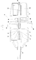
- FIG. 1 is cross- section of an x-ray tube 10 in accordance with an embodiment of the invention.
- the x-ray tube comprises an enclosure body 12 and a target assembly 14.
- the enclosure body and target assembly together define an evacuable enclosure 15.
- An electron beam is produced within the evacuable enclosure by an electron gun assembly.
- the electron gun assembly comprises a cathode 16 and an anode 18 which are spatially separated.
- a filament 20 is positioned at the cathode.
- the cathode 16 is connected to a high voltage power supply by a high power cable 22.
- the cable is connected to the enclosure by a suitable connector 24.
- the high voltage power supply allows the cathode 16 to be held at a very high negative potential while the anode 18 is held at a ground potential.
- the large potential difference between the anode and the cathode results in electrons being emitted from the cathode and accelerated towards the anode 18.
- the anode is shaped so that the electrons are accelerated towards a gap in the anode, towards the target assembly 14.
- the evacuable enclosure 15 is evacuated by vacuum pumps.
- An ion pump 26 provides a high vacuum and a getter pump 24 is provided to maintain the vacuum within the enclosure over time.
- the beam of electrons emitted from the filament is initially directed to the target assembly 14 by the construction of the anode 18.
- the electron beam can be further manipulated by electromagnets 32, 34 and 36.
- An aperture 30 is provided to remove the outermost electrons from the beam, ensuring that aberrations in the lenses are kept to a minimum, whilst maintaining a reasonable level of electron throughput and therefore tube power.
- the first set of electromagnets are centering coils 32,
- the centering coils 32 are arranged around the path of the electron beam and comprise four coils forming a quadrupole normal to the electron beam.
- the centering coils centre the electron beam accurately with respect to the aperture 30.
- a set of steering coils 34 are located around the path of the electron beam between the centering coils and the aperture.
- the steering coils allow the electron beam to be moved to impinge on different parts of the target assembly 14 by changing the angle of incidence of the electron beam through the aperture.
- there are four steering coils 34 which are also arranged as a quadrupole normal to the electron beam. Both the centering coils 32 and the steering coils are positioned outside of the enclosure body 12.
- a focussing magnet assembly 36 is provided between the steering coils and the target assembly.
- the focussing magnet assembly 36 operates to control the spot size of the electron beam on the target assembly, counteracting the space-charge effect that tends to expand the electron beam.
- the focussing magnet assembly comprises a single coil arranged coaxially with the path of the electron beam. The coil is housed in a soft iron body which directs the magnetic filed from the coil into a tight focussing pattern close to the electron beam.
- the focussing magnet assembly is provided within the enclosure body 12. The focussing magnet assembly 36 and the aperture 30 together form an electron beam focussing assembly.
- the target assembly 14 comprises a target material mounted on a substrate material.
- the target assembly14 is conflat sealed to the enclosure body 12 to provide a gas tight, evacuable enclosure 15.
- the evacuable enclosure has no elastomeric seals which are gas permeable and can degrade and so the enclosure can be maintained with a good vacuum for a long period of time.
- x-rays When the electron beam impinges on the target material x-rays are produced.
- the x-rays pass through the substrate material and exit the x-ray tube.
- the amount of x-rays produced from the target material is monitored by measuring the current flowing from the target to ground. This current correlates directly to the number of electrons incident on the target.
- the centering coils 32 and the steering coils 34 can be electrically controlled.
- the steering coils 34 can be controlled to alter the position at which the electron beam strikes the target.
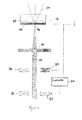
- Figures 2 and 3 are schematic illustrations of this process.
- Figures 2 and 3 show centering coils 32 and steering coils 34 connected to a controller 40.
- the controller 34 controls the voltage across the centering and steering coils.
- the controller 40 is shown connected to only one of each of the steering and centering coils but in fact the controller is connected to each of the centering and steering coils.
- Figures 2 and 3 also show the electron beam 52, the aperture 30 and the target assembly 14.
- the target assembly 14 comprise a layer of target material 42, which is in this example is tungsten, bonded to a substrate 44.
- the substrate is made from diamond, but may be made from beryllium or aluminium, or any low atomic number element or compound.
- the emitted x-rays 50 are illustrated as dotted lines.
- Figure 2 illustrates a configuration in which the steering coils 34 are not activated, i.e. there is no voltage across any of the steering coils.
- the electron beam 52 passes through the aperture 30 and is focussed on a first spot 46 on the target material. This configuration is maintained for a predetermined length of time, after which degradation of the target material at the first spot 46 becomes likely with continued use.
- the steering coils 34 are then activated and this causes the electron beam 52 to be deflected to a new position on the target as illustrated in Figure 3 .
- Figure 3 shows the steering coils 34 and centering coils 32 activated and controlled so that the electron beam 52 has a dogleg shape.
- the electron beam is still directed through the aperture 30 but the angle of incidence through the aperture is altered by the centering and steering coils.
- the position at which the electron beam impinges on the target is changed to a second position 48.
- the target has been eroded at the first position 46.
- the steering and centering coils can be electrically controlled to deflect the electron beam to a plurality of further positions on the target. If both the centering coils and the steering coils are arranged in a quadrupole a raster pattern of positions on the target material can be obtained. This deflection to a new position may be carried out automatically and periodically based on usage time of the x-ray tube. Alternatively, the deflection may be carried out based on a user input to the controller.
- the x-ray tube also allows for an automated assessment of the condition of the target to be made. This can be used to determine when and where to move the electron beam on the target.
- Figures 2 and 3 illustrate that the controller 40 may be configured to measure the current flowing to a ground potential from the target. This provides a measure of the number of electrons that are being absorbed by the target. If the target becomes eroded, as shown at position 46 in Figure 3 , so that the electron beam is incident on the substrate material, the number of electrons absorbed will be reduced, leading to a lower current measured by the controller 40. Accordingly, if the current measured by the controller suddenly drops, or drops below a threshold value, the controller may control the steering coils 32, 34 to adjust the position of the electron beam on the target. Alternatively, the controller may be configured to alert a user that the beam position needs to be altered by generating a visual or audible indication.
- FIG 4 is a cut-away, perspective view of a target assembly 14.
- the target assembly comprises a target 42 and a backscatter cup 48.
- the backscatter cup 48 comprises a central bore49, through which the electron beam passes before reaching the target 42.
- the backscatter cup absorbs electrons that have rebounded from the target.
- the backscatter cup and target are not electrically connected to one another.
- the controller may be configured to calculate a ratio of the current flowing from the target to ground to the current flowing from the backscatter cup to ground. This provides a ration of the number of electrons absorbed by the target to the number of electrons scattered by the target, and so is independent of the number of electrons in the electron beam.
- the measurement of current from the target and from the backscatter cup, or a ratio of these currents, can also be used to provide an image of the target surface.
- the controller can be configured to move the electron beam across the target to a plurality of discrete positions to perform a scan, such as a raster scan, of the target. At each discrete position, the current or ration of currents can be determined and recorded. In this way an image of the target condition over the entire available target surface can be obtained. This image can be used to decide on suitable positions for the electron beam.
- the beam can then be moved successively to new, suitable positions on a periodic basis or when the target at the current position has become degraded.
- the controller may be connected to the focussing magnet assembly 36 and may be configured to adjust the current supplied to the focussing magnet to adjust the focussing of the electron beam on the target.
- the focussing of the beam on the target may need to be adjusted on setting up the x-ray source and from time to time thereafter to compensate for environmental changes.
- the target may be provided with a pattern 60.
- the pattern may be a pattern formed of different materials or may be surface texturing that affects the number of electrons from the electron beam that are scattered or absorbed by the target.
- the controller is then configured to perform a scan of the target surface, as described above, by moving the electron beam to a plurality of different positions on the target. The resulting image can be compared to an expected image of the pattern.
- the controller then adjusts the focussing of the electron beam on the target by adjusting the supply of current to the focussing magnet assembly and another image recorded.
- the controller may continue to adjust the focus of the electron beam until the recorded image most closely matches the expected image. In other words, the focussing of the electron beam is adjusted until the sharpest possible image of the pattern is obtained.
- An x-ray tube in accordance with the invention has a target permanently fixed to the evacuated enclosure. As the electron beam can be deflected to different positions on the target, there is no need to provide a target that is movable relative to the enclosure body. This eliminates the need for an elastomer seal between the target and the enclosure body. The elimination of elastomer seals has significant benefits in terms of the performance and lifetime of the x-ray tube.
- the arrangement shown in Figures 1 , 2 and 3 provides for deflection of the electron beam prior to the passage of the electron beam through the focussing assembly of the aperture and the focussing magnet. This is advantageous as it allows for point of contact with the target to be altered accurately while allowing for tight control of the beam spot size.
- the focussing of the electron beam is substantially unaffected by the different deflections provided by the centering and steering coils and the electron beam always passes through the centre of the focussing assembly.
- the beam may be deflected either within or after the beam focussing assembly but that arrangement introduces aberrations in the beam and reduces control over the spot size of the beam on the target and so affects the spot size of the x-ray source.
- the arrangement described also provides the advantage of automatic monitoring of target condition and the ability to optimise the focus of the electron beam on the target.
Landscapes
- X-Ray Techniques (AREA)
Abstract
There is provided an x-ray source comprising: an enclosure body (12); a target (14) permanently fixed to or forming part of the enclosure body; an electron beam source within the enclosure body, the electron beam source configured to produce an electron beam along a beam path between the electron beam source and the target, the electron beam incident on the target to generate x-rays; an electron beam focussing assembly (36) positioned around the beam path between the target and the electron beam source; a first electron beam steering means (32) positioned around the beam path between the electron beam source and the electron beam focussing element; and a second beam steering means (34) positioned around the beam path between the first electron beam steering means and the target, wherein the first and second beam steering means are adjustable to alter a position of incidence of the beam on the target. The invention eliminates the need for an elastomer seal between the target and the enclosure body. The elimination of elastomer seals has significant benefits in terms of the performance and lifetime of the x-ray tube.
Description
- The invention relates to an x- ray source, and in particular to an x-ray tube with a fixed target having an improved lifetime.
- An x-ray tube assembly typically comprises an electron gun for producing an electron beam and a target material on which the electron beams impinges. The interaction of the electrons with the target causes the emission of x-rays from the target at the point at which the electrons strike the target. When the resulting x-rays are to be used in imaging applications it is advantageous for the x-rays to originate from a small area. To achieve this, the electron beam is tightly focussed onto a particular spot on the target.
- However, the small area of the target that is bombarded by electrons can wear out. If this happens, or before this happens, either the target must be replaced or repositioned, or the entire x-ray tube assembly must be replaced.
- In prior x-ray tubes, in order to allow the target to be repositioned so that the electron beam impinges on a new area of the target, the target is typically mounted to the x-ray tube using an elastomer seal. This allows the target to be slid or rotated to a new position, while the tube remains evacuated.
- However, the use of an elastomer seal has a significant disadvantage. For effective and reliable operation the x-ray tube must maintain a good vacuum. Even very small rates of ingress of atmospheric gases will shorten the target life and the life of the filament in the electron gun, and therefore reduce the operational lifetime of the x-ray tube. Elastomer seals are unable to maintain a good vacuum for long periods as gases can permeate through the elastomer itself. Also organic elastomers are susceptible to degradation on exposure to x-rays, leading to increased permeation and reduced reliability.
- It is an object of the present invention to provide an x-ray source with an improved lifetime without compromising the performance of the x-ray source or compromising the spot size of the electron beam on the target material.
- In accordance with a first aspect of the present invention, there is provided an x-ray source comprising:
- an enclosure body;
- a target permanently fixed to or forming part of the enclosure body;
- an electron beam source within the enclosure body, the electron beam source configured to produce an electron beam along a beam path between the electron beam source and the target, the electron beam incident on the target to generate x-rays;
- an electron beam focussing assembly positioned around the beam path between the target and the electron beam source;
- a first electron beam steering means positioned around the beam path between the electron beam source and the electron beam focussing element; and
- a second beam steering means positioned around the beam path between the first electron beam steering means and the target, wherein the first and second beam steering means are adjustable to alter a position of incidence of the beam on the target.
- As used herein, the target being "permanently fixed" to the enclosure body means that the target is fixed in a such a way that either the target, the enclosure body or some bonding material between the two, must be broken to move the target relative to the enclosure body. Crucially, the permanent fixing between the target and the enclosure body can be made using a fixing method or material that is relatively impermeable to gases compared to an elastomer seal and does not degrade on exposure to x-rays. Example fixing methods for permanently fixing the target to the enclosure body include brazing, conflat sealing and crushed metal sealing.
- The target may be formed from a high density material, such as tungsten, molybdenum or copper, which rapidly decelerates electrons. The target may further comprise a substrate material on which the high density material is coated or otherwise fixed. The substrate material may be permanently fixed to the enclosure body. The target may be fixed to the enclosure body so that the target, together with the enclosure body, forms an evacuable enclosure. In other words, the target may be required to complete the enclosure such that it is evacuable. Alternatively, the target may be fixed to the interior of the enclosure body, with the enclosure body alone forming a complete evacuable enclosure. As used herein, the term "evacuable" means capable of being evacuated so as to provide a vacuum within the enclosure.
- As used herein, "electron beam focussing assembly" means any assembly or component that can act to focus or limit an electron beam, including a simple aperture. This is distinct from "beam steering means" which is an assembly or component that operates to deflect an electron beam without significantly affecting the cross-sectional size or shape of the electron beam.
- Advantageously, the second beam steering means is positioned between the first electron beam steering means and the electron beam focussing assembly. This allows the focussing assembly to be positioned as close to the target as possible, providing maximal control over the beam spot size on the target.
- The first or second beam steering means, or both the first and second beam steering means, may comprise an electromagnet. The first or second beam steering means may then be positioned outside of the enclosure body. The first or second beam steering means, or both the first and second beam steering means, may comprise a quadrupole magnet and advantageously a "push-pull" type quadrupole magnet. The quadrupole magnet may provide magnetic flux in a direction substantially normal to the electron beam path. Alternatively, the first or second beam steering means, or both the first and second beam steering means, may comprise electrostatic beam steering means.
- The enclosure body may comprise an evacuable tube and may be formed from any suitable material, such as steel. The enclosure body may include one or more vacuum pumps that are operable to evacuate the enclosure body. The one or more pump may include a getter pump for maintaining a vacuum within the enclosure body.
- The electron beam source may comprise a cathode and an anode. The cathode may comprise a filament connected to a high voltage source. Electrons from the cathode at a high electrical potential are accelerated towards the anode to produce an electron beam.
- Advantageously, the x-ray source comprises a controller connected to the second beam steering means, the controller configured to adjust the second beam steering means to alter the position of the beam on the target. Preferably, the controller is configured to alter an angle of incidence of the beam relative to the electron beam focussing assembly. Advantageously, the controller is connected to the first beam steering means, the controller configured to adjust the first beam steering means to alter an angle of incidence of the beam relative to the electron beam focussing assembly. Advantageously the first and second beam steering means are configured to provide the electron beam with a dogleg shape.
- The controller may be configured to measure a current flowing from the target to a ground potential. This current, herein referred to as the target current, provides a measure of the number of electrons absorbed by the target. The x-ray source may further comprise a backscatter element configured to absorb electrons that are scattered by the target rather than being absorbed. The controller may also be configured to measure a current flowing from the backscatter element to a ground potential. This current, herein referred to as the backscatter current, provides a measure of the number of electrons scattered from the target. The controller may be configured to calculate a ratio of the target current to the backscatter current.
- The amount of electrons that is absorbed by a target from a given electron beam is dependent on the angle of incidence of the electron beam and the material properties of the target at the point of incidence of the beam. Measuring the target current or the backscatter current can therefore provide information about the condition of the target. This can be used for several purposes. Measuring a ratio of the target current to the backscatter current provides for a measure of the condition of the target that is independent of the number of electrons in the electron beam.
- Sudden changes in the target current, backscatter current or the ratio between the two (without a change in the position of the beam on the target or a change in the energy of the electron beam) may be indicative of damage or wear to the target. The controller may be configured to provide a measure of target current, backscatter current or a ratio of target current to backscatter current to a user interface, such as a display connected to or integral with the x-ray source. Alternatively, the controller may be configured to provide an alarm or alert to and end user based on a result of a comparison of target current, backscatter current or a ratio of target current to backscatter current, with a threshold value. The alert or alarm may be a visual alarm provided on a display connected to or integral with the x-ray source or may be an audible alarm. As a further alternative the controller may be configured to automatically alter the position of the beam on the target based on a result of a comparison of target current, backscatter current or a ratio of target current to backscatter current, with a threshold value.
- The controller may be configured to continuously alter the position of the beam on the target. The controller may be configured to alter the position of the beam on the target to perform a scan of the target, such that the beam is successively incident on the target at a plurality of different positions. The controller may be configured to measure the target current, backscatter current or a ratio of target current to backscatter current at each of the plurality of different positions. In this way, an image of the condition of the target or of a portion or portions of the target can be obtained. This image can be used by an end user, or automatically by the controller to select a new position to move the beam to for a period of operation of the x-ray source.
- The electron beam focussing assembly may comprise an aperture. The aperture may have a fixed size. The aperture may be formed by an aperture element that is directly or indirectly coupled to the enclosure body. The aperture removes the outermost electrons from the electron beam and removes or reduces beam aberrations. The controller is advantageously configured to adjust the first and second beam steering means to alter an angle of incidence of the beam relative to the aperture. The electron beam focussing assembly may comprise a magnetic focussing assembly, such as an electromagnet. Preferably, the electron beam focussing assembly comprises both an aperture and a magnetic focussing assembly. The aperture is advantageously provided within the magnetic focussing assembly. The magnetic focussing assembly may provide magnetic flux substantially parallel to the beam path. As an alternative to a magnetic focussing assembly, an electrostatic focussing assembly may be used.
- The target may be provided with a pattern that affects the electron absorption behaviour of the target. The pattern can be imaged by scanning the beam over the target and measuring the target current, backscatter current or a ratio of the target current to the backscatter current, to provide a means for optimising the focus of the electron beam on the target. The pattern may comprise a pattern of different materials on the target. Alternatively, or in addition, the pattern may comprise a patterned texture on the target surface. The pattern may be in the form of a grid or array.
- The focussing assembly may comprise an adjustable magnet or magnets, such as an electromagnet, or an adjustable electrostatic assembly. The focussing assembly may be adjusted so as to provide the sharpest image of the pattern. This corresponds to the smallest possible spot size of the electron beam on the target surface.
- Adjustment of the focussing assembly may be carried out automatically by the controller by using image processing software to compare recorded images with an ideal image of the pattern or by comparing recorded images of the pattern with one another. The controller may be configured to automatically adjust the focussing assembly to provide the sharpest image of the pattern, or to provide an image that most closely matches the ideal image, in an iterative process. Alternatively, the adjustment of the focussing assembly may be carried out manually.
- The focussing assembly may need to be adjusted during set up of the x-ray source and from time to time during the operational life of the x-ray source to compensate for environmental changes.
- In a second aspect of the invention, there is provided a method of measuring the condition of the target in an x-ray source in accordance with the first aspect, comprising:
- a) measuring a current flowing from the target to a ground potential when the electron beam is incident at a first position on the target to provide a first target value;
- b) moving the electron beam to a new position on the target;
- c) measuring a current flowing from the target to a ground potential when the electron beam is incident at the new position on the target to provide a new target value, wherein each target value is indicative of the condition of the target.
- The method may further comprise comparing the first and new target values with one another or with a set of expected target values to provide an assessment of the condition of the target at each of the first and new positions.
- Each target value may be a direct measure of the current flowing from the target to a ground potential or may be a ratio of the current flowing from the target to a ground potential to the current flowing from a backscatter element to a ground potential.
- Steps b) and c) may be repeated a plurality of times to provide a plurality of new target values corresponding to a plurality of new positions. In this way an image of target values may be generated. The electron beam may be moved to perform a raster scan of the target.
- The method may further comprise the step of selecting an operating position for the electron beam on the target based on the generated target values.
- In a third aspect of the invention, there is provided a method of adjusting the focus of the electron beam on the target in an x-ray source in accordance with the first aspect of the invention, wherein the target comprises a surface pattern of areas with different electron absorption characteristics, comprising :
- a) measuring a current flowing from the target to a ground potential when the electron beam is incident at a first position on the target to provide a first target value;
- b) moving the electron beam to a new position on the target;
- c) measuring a current flowing from the target to a ground potential when the electron beam is incident at the new position on the target to provide a new target value;
- d) repeating steps b) and c) a plurality of times to provide a set of target values corresponding to an image of at least a portion of the target;
- e) comparing the set of target values with an ideal set of target values to generate a first measure of beam focussing;
- f) adjusting a configuration of the electron beam focussing assembly;
- g) repeating steps a) to e) to generate a second measure of beam focussing;
- h) selecting a configuration of the electron beam focussing assembly based on a comparison of the first and second measures of beam focussing.
- The method may comprise an iterative process in which the configuration of the electron beam focussing assembly is iteratively adjusted until beam focussing is optimised.
- The adjustment of beam focussing in this manner may be carried out at set up of the x-ray source as well as periodically during the operation of the x-ray source.
- It should be clear that aspects described in relation to one aspect of the invention may equally be applied to other aspects of the invention.
- The invention will now be described in detail, by way of example only and with reference to the accompanying drawings, in which:
-
Figure 1 is a cross-section through an x-ray tube in accordance with the invention; -
Figure 2 is a schematic illustration of an x-ray source with an electron beam focussed in a first position; -
Figure 3 is a schematic illustration of an x-ray source with an electron beam focussed in a second position; and -
Figure 4 is a cut-away view of the target assembly in the x-ray tube ofFigure 1 . -
Figure 1 is cross- section of anx-ray tube 10 in accordance with an embodiment of the invention. The x-ray tube comprises anenclosure body 12 and atarget assembly 14. The enclosure body and target assembly together define anevacuable enclosure 15. An electron beam is produced within the evacuable enclosure by an electron gun assembly. The electron gun assembly comprises acathode 16 and ananode 18 which are spatially separated. Afilament 20 is positioned at the cathode. Thecathode 16 is connected to a high voltage power supply by ahigh power cable 22. The cable is connected to the enclosure by asuitable connector 24. The high voltage power supply allows thecathode 16 to be held at a very high negative potential while theanode 18 is held at a ground potential. The large potential difference between the anode and the cathode results in electrons being emitted from the cathode and accelerated towards theanode 18. The anode is shaped so that the electrons are accelerated towards a gap in the anode, towards thetarget assembly 14. - The
evacuable enclosure 15 is evacuated by vacuum pumps. Anion pump 26 provides a high vacuum and agetter pump 24 is provided to maintain the vacuum within the enclosure over time. - The beam of electrons emitted from the filament is initially directed to the
target assembly 14 by the construction of theanode 18. However, the electron beam can be further manipulated byelectromagnets aperture 30 is provided to remove the outermost electrons from the beam, ensuring that aberrations in the lenses are kept to a minimum, whilst maintaining a reasonable level of electron throughput and therefore tube power. - The first set of electromagnets are centering
coils 32, The centering coils 32 are arranged around the path of the electron beam and comprise four coils forming a quadrupole normal to the electron beam. The centering coils centre the electron beam accurately with respect to theaperture 30. A set of steering coils 34 are located around the path of the electron beam between the centering coils and the aperture. The steering coils allow the electron beam to be moved to impinge on different parts of thetarget assembly 14 by changing the angle of incidence of the electron beam through the aperture. In the embodiment shown inFigure 1 there are four steeringcoils 34, which are also arranged as a quadrupole normal to the electron beam. Both the centering coils 32 and the steering coils are positioned outside of theenclosure body 12. - A focussing
magnet assembly 36 is provided between the steering coils and the target assembly. The focussingmagnet assembly 36 operates to control the spot size of the electron beam on the target assembly, counteracting the space-charge effect that tends to expand the electron beam. The focussing magnet assembly comprises a single coil arranged coaxially with the path of the electron beam. The coil is housed in a soft iron body which directs the magnetic filed from the coil into a tight focussing pattern close to the electron beam. The focussing magnet assembly is provided within theenclosure body 12. The focussingmagnet assembly 36 and theaperture 30 together form an electron beam focussing assembly. - The
target assembly 14 comprises a target material mounted on a substrate material. The target assembly14 is conflat sealed to theenclosure body 12 to provide a gas tight,evacuable enclosure 15. The evacuable enclosure has no elastomeric seals which are gas permeable and can degrade and so the enclosure can be maintained with a good vacuum for a long period of time. - When the electron beam impinges on the target material x-rays are produced. The x-rays pass through the substrate material and exit the x-ray tube. The amount of x-rays produced from the target material is monitored by measuring the current flowing from the target to ground. This current correlates directly to the number of electrons incident on the target.
- The centering coils 32 and the steering coils 34 can be electrically controlled. In particular the steering coils 34 can be controlled to alter the position at which the electron beam strikes the target.
Figures 2 and3 are schematic illustrations of this process. -
Figures 2 and3 show centering coils 32 and steering coils 34 connected to acontroller 40. Thecontroller 34 controls the voltage across the centering and steering coils. For clarity thecontroller 40 is shown connected to only one of each of the steering and centering coils but in fact the controller is connected to each of the centering and steering coils.Figures 2 and3 also show theelectron beam 52, theaperture 30 and thetarget assembly 14. - The
target assembly 14 comprise a layer oftarget material 42, which is in this example is tungsten, bonded to asubstrate 44. In this embodiment, the substrate is made from diamond, but may be made from beryllium or aluminium, or any low atomic number element or compound. The emittedx-rays 50 are illustrated as dotted lines. -
Figure 2 illustrates a configuration in which the steering coils 34 are not activated, i.e. there is no voltage across any of the steering coils. Theelectron beam 52 passes through theaperture 30 and is focussed on afirst spot 46 on the target material. This configuration is maintained for a predetermined length of time, after which degradation of the target material at thefirst spot 46 becomes likely with continued use. The steering coils 34 are then activated and this causes theelectron beam 52 to be deflected to a new position on the target as illustrated inFigure 3 . -
Figure 3 shows the steering coils 34 and centeringcoils 32 activated and controlled so that theelectron beam 52 has a dogleg shape. The electron beam is still directed through theaperture 30 but the angle of incidence through the aperture is altered by the centering and steering coils. As a result the position at which the electron beam impinges on the target is changed to asecond position 48. As illustrated inFigure 3 the target has been eroded at thefirst position 46. - The steering and centering coils can be electrically controlled to deflect the electron beam to a plurality of further positions on the target. If both the centering coils and the steering coils are arranged in a quadrupole a raster pattern of positions on the target material can be obtained. This deflection to a new position may be carried out automatically and periodically based on usage time of the x-ray tube. Alternatively, the deflection may be carried out based on a user input to the controller.
- The x-ray tube also allows for an automated assessment of the condition of the target to be made. This can be used to determine when and where to move the electron beam on the target.
Figures 2 and3 illustrate that thecontroller 40 may be configured to measure the current flowing to a ground potential from the target. This provides a measure of the number of electrons that are being absorbed by the target. If the target becomes eroded, as shown atposition 46 inFigure 3 , so that the electron beam is incident on the substrate material, the number of electrons absorbed will be reduced, leading to a lower current measured by thecontroller 40. Accordingly, if the current measured by the controller suddenly drops, or drops below a threshold value, the controller may control the steering coils 32, 34 to adjust the position of the electron beam on the target. Alternatively, the controller may be configured to alert a user that the beam position needs to be altered by generating a visual or audible indication. - As well as, or as an alternative to, monitoring the number of electrons absorbed by the target, the controller may be configured to monitor the number of electrons scattered from the target.
Figure 4 is a cut-away, perspective view of atarget assembly 14. The target assembly comprises atarget 42 and abackscatter cup 48. Thebackscatter cup 48 comprises a central bore49, through which the electron beam passes before reaching thetarget 42. The backscatter cup absorbs electrons that have rebounded from the target. The backscatter cup and target are not electrically connected to one another. By measuring the current flowing from the backscatter cup to a ground potential, a measure of the number of electrons scattered from the target can be obtained. The controller can use this measure of scattered electrons to automatically determine when to move the electron beam to a new area on the target. - To provide a more reliable indication of target condition, the controller may be configured to calculate a ratio of the current flowing from the target to ground to the current flowing from the backscatter cup to ground. This provides a ration of the number of electrons absorbed by the target to the number of electrons scattered by the target, and so is independent of the number of electrons in the electron beam.
- The measurement of current from the target and from the backscatter cup, or a ratio of these currents, can also be used to provide an image of the target surface. The controller can be configured to move the electron beam across the target to a plurality of discrete positions to perform a scan, such as a raster scan, of the target. At each discrete position, the current or ration of currents can be determined and recorded. In this way an image of the target condition over the entire available target surface can be obtained. This image can be used to decide on suitable positions for the electron beam. The beam can then be moved successively to new, suitable positions on a periodic basis or when the target at the current position has become degraded.
- This imaging technique can also be exploited to optimise the focus of the beam on the target surface. The controller may be connected to the focussing
magnet assembly 36 and may be configured to adjust the current supplied to the focussing magnet to adjust the focussing of the electron beam on the target. The focussing of the beam on the target may need to be adjusted on setting up the x-ray source and from time to time thereafter to compensate for environmental changes. - As illustrated in
Figure 4 , the target may be provided with apattern 60. The pattern may be a pattern formed of different materials or may be surface texturing that affects the number of electrons from the electron beam that are scattered or absorbed by the target. The controller is then configured to perform a scan of the target surface, as described above, by moving the electron beam to a plurality of different positions on the target. The resulting image can be compared to an expected image of the pattern. The controller then adjusts the focussing of the electron beam on the target by adjusting the supply of current to the focussing magnet assembly and another image recorded. The controller may continue to adjust the focus of the electron beam until the recorded image most closely matches the expected image. In other words, the focussing of the electron beam is adjusted until the sharpest possible image of the pattern is obtained. - An x-ray tube in accordance with the invention has a target permanently fixed to the evacuated enclosure. As the electron beam can be deflected to different positions on the target, there is no need to provide a target that is movable relative to the enclosure body. This eliminates the need for an elastomer seal between the target and the enclosure body. The elimination of elastomer seals has significant benefits in terms of the performance and lifetime of the x-ray tube.
- The arrangement shown in
Figures 1 ,2 and3 provides for deflection of the electron beam prior to the passage of the electron beam through the focussing assembly of the aperture and the focussing magnet. This is advantageous as it allows for point of contact with the target to be altered accurately while allowing for tight control of the beam spot size. The focussing of the electron beam is substantially unaffected by the different deflections provided by the centering and steering coils and the electron beam always passes through the centre of the focussing assembly. As an alternative the beam may be deflected either within or after the beam focussing assembly but that arrangement introduces aberrations in the beam and reduces control over the spot size of the beam on the target and so affects the spot size of the x-ray source. The arrangement described also provides the advantage of automatic monitoring of target condition and the ability to optimise the focus of the electron beam on the target.
Claims (15)
- An x-ray source comprising:an enclosure body;a target permanently fixed to the enclosure body;an electron beam source within the enclosure body, the electron beam source configured to produce an electron beam along a beam path between the electron beam source and the target, the electron beam incident on the target to generate x-rays;an electron beam focussing assembly positioned around the beam path between the target and the electron beam source;a first electron beam steering means positioned around the beam path between the electron beam source and the electron beam focussing element; anda second beam steering means positioned around the beam path between the first electron beam steering means and the target, wherein the first and second beam steering means are adjustable to alter a position of incidence of the beam on the target.
- An x-ray source according to claim 1, wherein the second beam steering means is positioned between the first electron beam steering means and the electron beam focussing assembly.
- An x-ray source according to claim 1 or 2, wherein the first or second beam steering means, or both the first and second beam steering means, comprises an electromagnet.
- An x-ray source according to claim 3, wherein the first or second beam steering means, or both the first and second beam steering means, comprises a quadrupole magnet.
- An x-ray source according to any preceding claim, wherein the target is fixed to the enclosure body by brazing, conflat sealing or crushed metal.
- An x-ray source according to claim 5, wherein the target is fixed to the enclosure body so that the target, together with the enclosure body, forms an evacuable enclosure.
- An x-ray source according to any preceding claim, wherein the electron beam focussing assembly comprises an aperture, such that in use the electron beam passes through the aperture.
- An x-ray source according to any preceding claim, wherein the electron beam focussing assembly comprises a focussing magnet configured to adjust the spot size of the electron beam on the target.
- An x-ray source according to any preceding claim, further comprising a controller connected to the second beam steering means, the controller configured to adjust the second beam steering means to alter the position of the beam on the target.
- An x-ray source according to claim 9, wherein the controller is connected to the first beam steering means, the controller configured to adjust the first beam steering means to alter the angle of incidence of the beam through the electron beam focussing assembly.
- An x-ray source according to claim 9 or 10, wherein the first and second beam steering means are configured to provide the electron beam with a dogleg shape.
- An x-ray source according to claim 9, wherein the electron beam focussing assembly comprises an aperture, the controller configured to adjust the first beam steering means and the second beam steering means to alter the angle of incidence of the beam on the aperture.
- An x-ray source according to any one of claims 9 to 12, wherein the controller is configured to: measure a current flowing from the target to a ground potential, or to measure a current flowing from a backscatter element to a ground potential, or to calculate a ratio of the current flowing from the target to a ground potential to the current flowing from a backscatter element to a ground potential, and to automatically alter the position of the beam on the target based on a result of a comparison of the measured current or ration of currents with a threshold value.
- A method of measuring the condition of the target in an x-ray source in accordance with the first aspect, comprising:a) measuring a current flowing from the target to a ground potential when the electron beam is incident at a first position on the target to provide a first target value;b) moving the electron beam to a new position on the target;c) measuring a current flowing from the target to a ground potential when the electron beam is incident at the new position on the target to provide a new target value, wherein each target value is indicative of the condition of the target.
- A method of adjusting the focus of the electron beam on the target in an x-ray source in accordance with the first aspect of the invention, wherein the target comprises a surface pattern of areas with different electron absorption characteristics, comprising :a) measuring a current flowing from the target to a ground potential when the electron beam is incident at a first position on the target to provide a first target value;b) moving the electron beam to a new position on the target;c) measuring a current flowing from the target to a ground potential when the electron beam is incident at the new position on the target to provide a new target value;d) repeating steps b) and c) a plurality of times to provide a set of target values corresponding to an image of at least a portion of the target;e) comparing the set of target values with an ideal set of target values to generate a first measure of beam focussing;f) adjusting a configuration of the electron beam focussing assembly;g) repeating steps a) to e) to generate a second measure of beam focussing;h) selecting a configuration of the electron beam focussing assembly based on a comparison of the first and second measures of beam focussing.
Priority Applications (4)
| Application Number | Priority Date | Filing Date | Title |
|---|---|---|---|
| EP13154072.6A EP2763156A1 (en) | 2013-02-05 | 2013-02-05 | X-ray source with improved target lifetime |
| GB1512823.4A GB2525111B (en) | 2013-02-05 | 2014-02-04 | X-ray source with improved target lifetime |
| PCT/US2014/014535 WO2014123835A1 (en) | 2013-02-05 | 2014-02-04 | X-ray source with improved target lifetime |
| DE212014000043.2U DE212014000043U1 (en) | 2013-02-05 | 2014-02-04 | X-ray source with improved target lifetime |
Applications Claiming Priority (1)
| Application Number | Priority Date | Filing Date | Title |
|---|---|---|---|
| EP13154072.6A EP2763156A1 (en) | 2013-02-05 | 2013-02-05 | X-ray source with improved target lifetime |
Publications (1)
| Publication Number | Publication Date |
|---|---|
| EP2763156A1 true EP2763156A1 (en) | 2014-08-06 |
Family
ID=47709950
Family Applications (1)
| Application Number | Title | Priority Date | Filing Date |
|---|---|---|---|
| EP13154072.6A Withdrawn EP2763156A1 (en) | 2013-02-05 | 2013-02-05 | X-ray source with improved target lifetime |
Country Status (4)
| Country | Link |
|---|---|
| EP (1) | EP2763156A1 (en) |
| DE (1) | DE212014000043U1 (en) |
| GB (1) | GB2525111B (en) |
| WO (1) | WO2014123835A1 (en) |
Cited By (8)
| Publication number | Priority date | Publication date | Assignee | Title |
|---|---|---|---|---|
| CN105047509A (en) * | 2015-07-24 | 2015-11-11 | 中国科学院电工研究所 | Focusing device for large-beam-current electronic beam targeting X-ray source with micro beams |
| WO2019141454A3 (en) * | 2018-01-17 | 2019-09-12 | Yxlon International Gmbh | Transmission target for an open x-ray tube, open x-ray tube, method for detecting a transmission target, and method for adjusting the characteristics of said transmission target |
| JP2022167828A (en) * | 2021-04-23 | 2022-11-04 | カール・ツァイス・エックス-レイ・マイクロスコピー・インコーポレイテッド | Fiber-optic communication for embedded electronics in x-ray generator |
| EP4254464A1 (en) * | 2022-03-29 | 2023-10-04 | Excillum AB | Determination of operational state of x-ray source |
| US11864300B2 (en) | 2021-04-23 | 2024-01-02 | Carl Zeiss X-ray Microscopy, Inc. | X-ray source with liquid cooled source coils |
| US12035451B2 (en) | 2021-04-23 | 2024-07-09 | Carl Zeiss X-Ray Microscopy Inc. | Method and system for liquid cooling isolated x-ray transmission target |
| EP4358112A3 (en) * | 2022-10-18 | 2024-07-31 | Carl Zeiss X-Ray Microscopy, Inc. | Reflection target x-ray source with steered beam on target |
| WO2024218040A1 (en) * | 2023-04-18 | 2024-10-24 | Excillum Ab | Secondary radiation mitigation |
Families Citing this family (3)
| Publication number | Priority date | Publication date | Assignee | Title |
|---|---|---|---|---|
| GB2565138A (en) * | 2017-08-04 | 2019-02-06 | Adaptix Ltd | X-ray generator |
| US11007381B2 (en) * | 2017-11-16 | 2021-05-18 | Varian Medical Systems, Inc | Increased beam output and dynamic field shaping for radiotherapy system |
| CN117594400A (en) * | 2023-11-02 | 2024-02-23 | 上海联影医疗科技股份有限公司 | Ray source assembly, radiation control method and computer-readable storage medium |
Citations (7)
| Publication number | Priority date | Publication date | Assignee | Title |
|---|---|---|---|---|
| WO2000058991A1 (en) * | 1999-03-26 | 2000-10-05 | Bede Scientific Instruments Limited | Method and apparatus for prolonging the life of an x-ray target |
| US6282263B1 (en) * | 1996-09-27 | 2001-08-28 | Bede Scientific Instruments Limited | X-ray generator |
| EP1557864A1 (en) * | 2004-01-23 | 2005-07-27 | Tohken Co., Ltd. | X-ray microscopic inspection apparatus |
| US20070051907A1 (en) * | 2005-09-03 | 2007-03-08 | Alfred Reinhold | Device for generating X-ray or XUV radiation |
| US20100141151A1 (en) * | 2006-12-28 | 2010-06-10 | Yxlon International Feinfocus Gmbh | X-ray tube and method for examining a target by scanning with an electron beam |
| GB2473137A (en) * | 2009-08-31 | 2011-03-02 | Hamamatsu Photonics Kk | An X-ray generator |
| DE102010009276A1 (en) * | 2010-02-25 | 2011-08-25 | Dürr Dental AG, 74321 | X-ray tube and system for producing X-ray images for dental or orthodontic diagnostics |
Family Cites Families (2)
| Publication number | Priority date | Publication date | Assignee | Title |
|---|---|---|---|---|
| JP4375110B2 (en) * | 2004-05-12 | 2009-12-02 | 株式会社島津製作所 | X-ray generator |
| JP2006024522A (en) * | 2004-07-09 | 2006-01-26 | Shimadzu Corp | X-ray generator |
-
2013
- 2013-02-05 EP EP13154072.6A patent/EP2763156A1/en not_active Withdrawn
-
2014
- 2014-02-04 GB GB1512823.4A patent/GB2525111B/en active Active
- 2014-02-04 DE DE212014000043.2U patent/DE212014000043U1/en not_active Expired - Lifetime
- 2014-02-04 WO PCT/US2014/014535 patent/WO2014123835A1/en not_active Ceased
Patent Citations (7)
| Publication number | Priority date | Publication date | Assignee | Title |
|---|---|---|---|---|
| US6282263B1 (en) * | 1996-09-27 | 2001-08-28 | Bede Scientific Instruments Limited | X-ray generator |
| WO2000058991A1 (en) * | 1999-03-26 | 2000-10-05 | Bede Scientific Instruments Limited | Method and apparatus for prolonging the life of an x-ray target |
| EP1557864A1 (en) * | 2004-01-23 | 2005-07-27 | Tohken Co., Ltd. | X-ray microscopic inspection apparatus |
| US20070051907A1 (en) * | 2005-09-03 | 2007-03-08 | Alfred Reinhold | Device for generating X-ray or XUV radiation |
| US20100141151A1 (en) * | 2006-12-28 | 2010-06-10 | Yxlon International Feinfocus Gmbh | X-ray tube and method for examining a target by scanning with an electron beam |
| GB2473137A (en) * | 2009-08-31 | 2011-03-02 | Hamamatsu Photonics Kk | An X-ray generator |
| DE102010009276A1 (en) * | 2010-02-25 | 2011-08-25 | Dürr Dental AG, 74321 | X-ray tube and system for producing X-ray images for dental or orthodontic diagnostics |
Cited By (14)
| Publication number | Priority date | Publication date | Assignee | Title |
|---|---|---|---|---|
| CN105047509A (en) * | 2015-07-24 | 2015-11-11 | 中国科学院电工研究所 | Focusing device for large-beam-current electronic beam targeting X-ray source with micro beams |
| WO2019141454A3 (en) * | 2018-01-17 | 2019-09-12 | Yxlon International Gmbh | Transmission target for an open x-ray tube, open x-ray tube, method for detecting a transmission target, and method for adjusting the characteristics of said transmission target |
| CN111602222A (en) * | 2018-01-17 | 2020-08-28 | 依科视郎国际有限公司 | Transmission target for an open X-ray tube, method for identifying a transmission target and method for adjusting a characteristic parameter of the transmission target |
| US12035451B2 (en) | 2021-04-23 | 2024-07-09 | Carl Zeiss X-Ray Microscopy Inc. | Method and system for liquid cooling isolated x-ray transmission target |
| EP4080523A3 (en) * | 2021-04-23 | 2023-02-08 | Carl Zeiss X-Ray Microscopy, Inc. | Fiber-optic communication for embedded electronics in x-ray generator |
| US11864300B2 (en) | 2021-04-23 | 2024-01-02 | Carl Zeiss X-ray Microscopy, Inc. | X-ray source with liquid cooled source coils |
| US11961694B2 (en) | 2021-04-23 | 2024-04-16 | Carl Zeiss X-ray Microscopy, Inc. | Fiber-optic communication for embedded electronics in x-ray generator |
| JP2022167828A (en) * | 2021-04-23 | 2022-11-04 | カール・ツァイス・エックス-レイ・マイクロスコピー・インコーポレイテッド | Fiber-optic communication for embedded electronics in x-ray generator |
| EP4254464A1 (en) * | 2022-03-29 | 2023-10-04 | Excillum AB | Determination of operational state of x-ray source |
| WO2023186870A1 (en) * | 2022-03-29 | 2023-10-05 | Excillum Ab | Determination of operational state of x-ray source |
| US20250220799A1 (en) * | 2022-03-29 | 2025-07-03 | Excillum Ab | Determination of operational state of x-ray source |
| EP4358112A3 (en) * | 2022-10-18 | 2024-07-31 | Carl Zeiss X-Ray Microscopy, Inc. | Reflection target x-ray source with steered beam on target |
| US12213238B2 (en) | 2022-10-18 | 2025-01-28 | Carl Zeiss X-ray Microscopy, Inc. | Reflection target X-ray source with steered beam on target |
| WO2024218040A1 (en) * | 2023-04-18 | 2024-10-24 | Excillum Ab | Secondary radiation mitigation |
Also Published As
| Publication number | Publication date |
|---|---|
| GB201512823D0 (en) | 2015-09-02 |
| GB2525111A (en) | 2015-10-14 |
| GB2525111B (en) | 2018-10-31 |
| DE212014000043U1 (en) | 2015-09-24 |
| WO2014123835A1 (en) | 2014-08-14 |
Similar Documents
| Publication | Publication Date | Title |
|---|---|---|
| WO2014123835A1 (en) | X-ray source with improved target lifetime | |
| EP3093867B1 (en) | X-ray generator and adjustment method therefor | |
| JP4113032B2 (en) | Electron gun and electron beam exposure apparatus | |
| US7046767B2 (en) | X-ray generator | |
| RU2634906C2 (en) | Device and method for obtaining distributed x-rays | |
| US20140105367A1 (en) | X-ray generating apparatus | |
| TW201618149A (en) | Charged particle beam specimen inspection system and method for operation thereof | |
| JP7604032B2 (en) | Mechanical alignment of the X-ray source | |
| US8759761B2 (en) | Charged corpuscular particle beam irradiating method, and charged corpuscular particle beam apparatus | |
| JP2016213078A5 (en) | ||
| JPWO2008102435A1 (en) | Electron gun, electron beam exposure apparatus and exposure method | |
| CN109119312B (en) | Magnetic scanning type X-ray tube | |
| US20130087703A1 (en) | Electron microscope | |
| US12512290B2 (en) | X-ray tube with flexible intensity adjustment | |
| US8461526B2 (en) | Electron beam column and methods of using same | |
| CA2558216A1 (en) | Device for generating x-ray or xuv radiation | |
| JP5458472B2 (en) | X-ray tube | |
| US10431415B2 (en) | X-ray tube ion barrier | |
| CN112512196B (en) | Array X-ray source and X-ray imaging equipment | |
| JP2007305337A (en) | Microfocus x-ray tube | |
| JP6178296B2 (en) | Electron beam emission tube | |
| US8987692B2 (en) | High brightness electron gun, system using the same, and method of operating thereof | |
| JP4621267B2 (en) | Electron beam drawing method | |
| US10381189B2 (en) | X-ray tube | |
| KR20170089386A (en) | X-ray tube |
Legal Events
| Date | Code | Title | Description |
|---|---|---|---|
| PUAI | Public reference made under article 153(3) epc to a published international application that has entered the european phase |
Free format text: ORIGINAL CODE: 0009012 |
|
| 17P | Request for examination filed |
Effective date: 20130205 |
|
| AK | Designated contracting states |
Kind code of ref document: A1 Designated state(s): AL AT BE BG CH CY CZ DE DK EE ES FI FR GB GR HR HU IE IS IT LI LT LU LV MC MK MT NL NO PL PT RO RS SE SI SK SM TR |
|
| AX | Request for extension of the european patent |
Extension state: BA ME |
|
| STAA | Information on the status of an ep patent application or granted ep patent |
Free format text: STATUS: THE APPLICATION IS DEEMED TO BE WITHDRAWN |
|
| 18D | Application deemed to be withdrawn |
Effective date: 20150207 |