EP2762846A2 - Temperaturmessvorrichtung - Google Patents
Temperaturmessvorrichtung Download PDFInfo
- Publication number
- EP2762846A2 EP2762846A2 EP14153517.9A EP14153517A EP2762846A2 EP 2762846 A2 EP2762846 A2 EP 2762846A2 EP 14153517 A EP14153517 A EP 14153517A EP 2762846 A2 EP2762846 A2 EP 2762846A2
- Authority
- EP
- European Patent Office
- Prior art keywords
- temperature
- atomic spectral
- intensity ratio
- intensity
- light
- Prior art date
- Legal status (The legal status is an assumption and is not a legal conclusion. Google has not performed a legal analysis and makes no representation as to the accuracy of the status listed.)
- Withdrawn
Links
- 238000005259 measurement Methods 0.000 claims abstract description 145
- 230000003595 spectral effect Effects 0.000 claims abstract description 133
- 230000003287 optical effect Effects 0.000 claims abstract description 129
- 238000009529 body temperature measurement Methods 0.000 claims abstract description 82
- 238000000295 emission spectrum Methods 0.000 claims abstract description 60
- 238000000605 extraction Methods 0.000 claims abstract description 12
- 239000000284 extract Substances 0.000 claims abstract description 11
- 239000010949 copper Substances 0.000 claims description 22
- RYGMFSIKBFXOCR-UHFFFAOYSA-N Copper Chemical compound [Cu] RYGMFSIKBFXOCR-UHFFFAOYSA-N 0.000 claims description 21
- 229910052802 copper Inorganic materials 0.000 claims description 21
- CURLTUGMZLYLDI-UHFFFAOYSA-N Carbon dioxide Chemical compound O=C=O CURLTUGMZLYLDI-UHFFFAOYSA-N 0.000 claims description 6
- 229910018503 SF6 Inorganic materials 0.000 claims description 3
- 229910002092 carbon dioxide Inorganic materials 0.000 claims description 3
- 239000001569 carbon dioxide Substances 0.000 claims description 3
- SFZCNBIFKDRMGX-UHFFFAOYSA-N sulfur hexafluoride Chemical compound FS(F)(F)(F)(F)F SFZCNBIFKDRMGX-UHFFFAOYSA-N 0.000 claims description 3
- 229960000909 sulfur hexafluoride Drugs 0.000 claims description 3
- 230000005540 biological transmission Effects 0.000 description 24
- PXGOKWXKJXAPGV-UHFFFAOYSA-N Fluorine Chemical compound FF PXGOKWXKJXAPGV-UHFFFAOYSA-N 0.000 description 13
- 229910052731 fluorine Inorganic materials 0.000 description 13
- 239000011737 fluorine Substances 0.000 description 13
- 238000000034 method Methods 0.000 description 9
- 238000010276 construction Methods 0.000 description 6
- 238000006243 chemical reaction Methods 0.000 description 5
- 238000001514 detection method Methods 0.000 description 4
- 239000000126 substance Substances 0.000 description 4
- 239000002184 metal Substances 0.000 description 3
- 229910052751 metal Inorganic materials 0.000 description 3
- 230000035939 shock Effects 0.000 description 3
- 238000002485 combustion reaction Methods 0.000 description 2
- 238000004880 explosion Methods 0.000 description 2
- 239000013307 optical fiber Substances 0.000 description 2
- 230000000704 physical effect Effects 0.000 description 2
- 101000582320 Homo sapiens Neurogenic differentiation factor 6 Proteins 0.000 description 1
- 102100030589 Neurogenic differentiation factor 6 Human genes 0.000 description 1
- 230000007423 decrease Effects 0.000 description 1
- 230000001419 dependent effect Effects 0.000 description 1
- 230000005284 excitation Effects 0.000 description 1
- 239000011521 glass Substances 0.000 description 1
- 238000009434 installation Methods 0.000 description 1
- 239000002344 surface layer Substances 0.000 description 1
- 239000005341 toughened glass Substances 0.000 description 1
- 230000001052 transient effect Effects 0.000 description 1
- 230000007704 transition Effects 0.000 description 1
Images


Classifications
-
- G—PHYSICS
- G01—MEASURING; TESTING
- G01J—MEASUREMENT OF INTENSITY, VELOCITY, SPECTRAL CONTENT, POLARISATION, PHASE OR PULSE CHARACTERISTICS OF INFRARED, VISIBLE OR ULTRAVIOLET LIGHT; COLORIMETRY; RADIATION PYROMETRY
- G01J5/00—Radiation pyrometry, e.g. infrared or optical thermometry
- G01J5/0014—Radiation pyrometry, e.g. infrared or optical thermometry for sensing the radiation from gases, flames
-
- G—PHYSICS
- G01—MEASURING; TESTING
- G01J—MEASUREMENT OF INTENSITY, VELOCITY, SPECTRAL CONTENT, POLARISATION, PHASE OR PULSE CHARACTERISTICS OF INFRARED, VISIBLE OR ULTRAVIOLET LIGHT; COLORIMETRY; RADIATION PYROMETRY
- G01J5/00—Radiation pyrometry, e.g. infrared or optical thermometry
- G01J5/60—Radiation pyrometry, e.g. infrared or optical thermometry using determination of colour temperature
- G01J5/602—Radiation pyrometry, e.g. infrared or optical thermometry using determination of colour temperature using selective, monochromatic or bandpass filtering
-
- G—PHYSICS
- G01—MEASURING; TESTING
- G01J—MEASUREMENT OF INTENSITY, VELOCITY, SPECTRAL CONTENT, POLARISATION, PHASE OR PULSE CHARACTERISTICS OF INFRARED, VISIBLE OR ULTRAVIOLET LIGHT; COLORIMETRY; RADIATION PYROMETRY
- G01J5/00—Radiation pyrometry, e.g. infrared or optical thermometry
- G01J2005/0074—Radiation pyrometry, e.g. infrared or optical thermometry having separate detection of emissivity
-
- G—PHYSICS
- G01—MEASURING; TESTING
- G01J—MEASUREMENT OF INTENSITY, VELOCITY, SPECTRAL CONTENT, POLARISATION, PHASE OR PULSE CHARACTERISTICS OF INFRARED, VISIBLE OR ULTRAVIOLET LIGHT; COLORIMETRY; RADIATION PYROMETRY
- G01J5/00—Radiation pyrometry, e.g. infrared or optical thermometry
- G01J5/02—Constructional details
- G01J5/06—Arrangements for eliminating effects of disturbing radiation; Arrangements for compensating changes in sensitivity
-
- G—PHYSICS
- G01—MEASURING; TESTING
- G01J—MEASUREMENT OF INTENSITY, VELOCITY, SPECTRAL CONTENT, POLARISATION, PHASE OR PULSE CHARACTERISTICS OF INFRARED, VISIBLE OR ULTRAVIOLET LIGHT; COLORIMETRY; RADIATION PYROMETRY
- G01J5/00—Radiation pyrometry, e.g. infrared or optical thermometry
- G01J5/02—Constructional details
- G01J5/08—Optical arrangements
- G01J5/0818—Waveguides
- G01J5/0821—Optical fibres
-
- G—PHYSICS
- G01—MEASURING; TESTING
- G01J—MEASUREMENT OF INTENSITY, VELOCITY, SPECTRAL CONTENT, POLARISATION, PHASE OR PULSE CHARACTERISTICS OF INFRARED, VISIBLE OR ULTRAVIOLET LIGHT; COLORIMETRY; RADIATION PYROMETRY
- G01J5/00—Radiation pyrometry, e.g. infrared or optical thermometry
- G01J5/02—Constructional details
- G01J5/08—Optical arrangements
- G01J5/0896—Optical arrangements using a light source, e.g. for illuminating a surface
-
- G—PHYSICS
- G01—MEASURING; TESTING
- G01J—MEASUREMENT OF INTENSITY, VELOCITY, SPECTRAL CONTENT, POLARISATION, PHASE OR PULSE CHARACTERISTICS OF INFRARED, VISIBLE OR ULTRAVIOLET LIGHT; COLORIMETRY; RADIATION PYROMETRY
- G01J5/00—Radiation pyrometry, e.g. infrared or optical thermometry
- G01J5/80—Calibration
- G01J5/802—Calibration by correcting for emissivity
-
- G—PHYSICS
- G01—MEASURING; TESTING
- G01K—MEASURING TEMPERATURE; MEASURING QUANTITY OF HEAT; THERMALLY-SENSITIVE ELEMENTS NOT OTHERWISE PROVIDED FOR
- G01K11/00—Measuring temperature based upon physical or chemical changes not covered by groups G01K3/00, G01K5/00, G01K7/00 or G01K9/00
- G01K11/12—Measuring temperature based upon physical or chemical changes not covered by groups G01K3/00, G01K5/00, G01K7/00 or G01K9/00 using changes in colour, translucency or reflectance
Definitions
- Embodiments described herein relate generally to a temperature measurement device.
- the method In order to measure the temperature of a plasma, which is a high-speed transient phenomenon, the method has been considered of calculating the temperature by measuring the light emitted by the plasma. Conventionally, the method has been considered of finding the temperature by selectively simultaneously detecting the intensity of two atomic spectral lines that are emitted by the plasma and calculating the temperature from the ratio of their intensities.
- this method is subject to the problem that, as well as the atomic spectral lines, the plasma emission spectrum contains a continuous optical component, so when this continuous optical component is added in, the measurement accuracy is lowered.
- An example of such a method is described in Takeuchi et al.
- Non-Patent Reference “Temperature and Metal Vapor Near the Cathode in Copper Breaking Arcs According to Spectroscopic Measurement", IEEE Transactions on Plasma Science, Vol. 28, No. 3, pp. 991-999, 2000 (hereinafter referred to as Non-Patent Reference).
- a temperature measurement device that measures temperature accurately using the emission spectrum of the measurement subject.
- a temperature measurement device comprises the following construction.
- the light collection means collects the emission spectrum of the measurement subject.
- the extraction means extracts light having wavelengths of an atomic spectral lines, and light having a wavelength in a wavelength region where there are no atomic spectral lines from the emission spectrum collected by the aforementioned light collection means.
- the optical intensity calculation means calculates the intensity of the respective beams extracted by the aforementioned extraction means.
- the temperature measurement means calculates the temperature of the aforementioned measurement subject, based on the intensities of the respective beams calculated by the aforementioned optical intensity calculation means.
- a temperature measurement device measures the temperature of a measurement subject using the emission spectrum of the measurement subject. Specifically, the temperature measurement device selectively detects two atomic spectral lines of the emission spectrum of the measurement subject and an optical component having a wavelength other than the wavelength of the atomic spectral lines, and measures the temperature of the measurement subject from their respective intensities.
- the temperature measurement device measures the intensities (IA and IB) of optical components having the two wavelengths ( ⁇ a and ⁇ b) of these atomic spectral lines, of the emission spectrum.
- the temperature measurement device measures the intensity (IC) of an optical component having a wavelength ( ⁇ c) other than the wavelength of the atomic spectral lines, of the emission spectrum.
- the temperature measurement device then calculates the temperature of the measurement subject from the intensity IA of the optical component having the wavelength ⁇ a, the intensity IB of the optical component having the wavelength ⁇ b, and the intensity IC of the optical component having the wavelength ⁇ c.
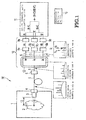
- FIG. 1 is a view showing diagrammatically an example layout of a temperature measurement device 20 according to a first embodiment.
- a temperature measurement device 20 comprises: an individual container 1 that accommodates a measurement subject 2; an optical input section 3 that collects the light of the emission spectrum of the measurement subject in the individual container 1; an adapter 4 that holds the optical input section 3 in a fixed manner; a transmission section 5 that transmits the emission spectrum collected by the optical input section 3; an amount of light adjustment section 6 that adjusts the amount of light of the emission spectrum collected by the optical input section 3; a specified wavelength intensity detection section 10 that detects the intensity of a spectral line having a specified wavelength, from the emission spectrum whose amount of light has been adjusted by the amount of light adjustment section 6; an optical intensity ratio calculation section 11 that calculates the intensity ratio of the atomic spectral lines from each of the spectral intensities detected by the specified wavelength intensity detection section 10; and a temperature calculation section 15.
- the specified wavelength intensity detection section 10 comprises a wavelength selection section 7 that selects and extracts light having a specified wavelength from the emission spectrum wherein the amount of light has been adjusted by the amount of light adjustment section 6, detectors 8a to 8c that output voltages dependent on the intensity of the light extracted by the wavelength selection section 7, and calibration sections 9a to 9c that calculate the intensity of the light from the voltages output by the detectors 8a to 8c.
- the wavelength selection section 7 is arranged within a temperature adjustment section 12 that adjusts the temperature of the interior to a fixed value.
- the individual container 1 has a space that stores a measurement subject 2 in its interior.
- the space provided by the individual container 1 is of a size and shape in accordance with that of the measurement subject 2.
- the individual container 1 may be a container of cylindrical shape or box shape, but the shape of the individual container 1 is not restricted to a specific shape.
- the individual container 1 has a strength capable of withstanding for example shock or heat generated by the measurement subject 2.
- the individual container 1 may be formed of metal or the like, but the substance used to constitute the individual container 1 is not restricted to a specific substance.
- the individual container 1 may be a container such as is employed as a power gas circuit breaker or in other applications such as the cylinder of an internal combustion engine. Also, the individual container 1 may be a container for measuring the measurement subject 2.
- the inside surface of the individual container 1 is processed to a specular finish at least in the portion that enters the range of the field of view of the optical input section 3.
- the optical input section 3 collects only the light that is emitted at this inside surface that is processed to a specular finish.
- Such a substance that has been processed to a specular finish emits light whose intensity shows little variation with change in temperature. Consequently, the portion of the optical input section 3 of the inside surface of the individual container 1 that enters the range of field of view emits light whose intensity shows little variation with change in temperature. Consequently, the optical input section 3 can collect the emission spectrum of the measurement subject 2 with no possibility of the light that is emitted and collected being influenced by change of temperature of the individual container 1.
- a hole that communicates with the interior is provided in part of the individual container 1, for the purpose of installing an adapter 4 therein.
- the hole is provided in a position in the vicinity of the measurement subject 2, so as to facilitate collection of the emission spectrum of the measurement subject 2, but is not restricted to being in a specific position.
- the measurement subject 2 is the object whose temperature is being measured by the temperature measurement device 20.
- the measurement subject 2 may be for example a phenomenon (instantaneous phenomenon) whereby an abrupt change in temperature occurs in a short time (for example from a few milliseconds to a few microseconds).
- the measurement subject 2 could be an explosion, combustion, plasma or a chemical reaction.
- the measurement subject 2 is not restricted to instantaneous phenomena and is not restricted to specific substances or phenomena.
- the optical input section 3 collects the emission spectrum of the measurement subject 2 from its tip. Also, the optical input section 3 supplies the collected emission spectrum to the amount of light adjustment section 6 through a transmission line 5.
- the optical input section 3 is held by the adapter 4.
- the optical input section 3 may be arranged projecting into the interior of the individual container 1, or may be embedded in the adapter 4 without projecting into the interior of the individual container 1.
- the surface layer section of the optical input section 3 facing the measurement subject 2 has a strength capable of withstanding for example shock or heat generated by the measurement subject 2.
- the surface section of the optical input section 3 facing the measurement subject 2 is formed for example of heat-resistant glass or toughened glass.
- the optical input section 3 is provided with a lens having a focal point distance 13 or a focal distance 13 in its interior.
- the optical input section 3 can collect light from a portion that is separated from the input section 3 by the focal point distance 13.
- the optical input section 3 can thereby collect the emission spectrum generated by the portion (measurement location) of the measurement subject 2 that is separated from the optical input section 3 by the focal point distance 13.
- the temperature measurement device 20 can measure the temperature of the aforementioned measurement location of the measurement subject 2.
- the focal point distance 13 of the lens can be altered at will. In this way, the location at which the temperature is measured by the temperature measurement device 20 can easily be altered.
- the adapter 4 holds the optical input section 3 fixed.
- the adapter 4 is installed in the individual container 1 in such a way as to block the hole that is provided in the individual container 1. Also, the adapter 4 holds fixed one end of the transmission line 5.
- the adapter 4 optically connects the optical input section 3 and the transmission line 5 by holding the transmission line 5 and the optical input section 3 fixed.
- the transmission path 5 transmits the emission spectrum collected by the optical input section 3 to the amount of light adjustment section 6. Also, the transmission path 5 transmits to the wavelength selection section 7 the emission spectrum whose amount of light has been adjusted by the amount of light adjustment section 6. Also, the transmission path 5 transmits to the detectors 8a, 8b, 8c the light that is supplied by the wavelength selection section 7.
- the transmission path 5 has the function of transmitting light from one end of the transmission path 5 to the other end.
- the transmission path 5 may be for example an optical fiber.
- the amount of light adjustment section 6 adjusts the amount of light of the emission spectrum supplied by the optical input section 3 to a suitable amount of light. Specifically, the amount of light adjustment section 6 adjusts the amount of light of the emission spectrum supplied by the optical input section 3 to an amount of light capable of detection by the detectors 8a to 8c. Specifically, the amount of light adjustment section 6 reduces all of the optical components of the emission spectrum in a uniform ratio. For example, if the amount of light of the emission spectrum that is supplied by the optical input section 3 exceeds the amount of light that can be detected by the detectors 8, no difference in intensity of the atomic spectral lines detected by the detectors 8 is manifested, so the temperature measurement device 20 cannot calculate the temperature of the measurement subject 2.
- the amount of light adjustment section 6 would reduce the amount of light of the emission spectrum to an amount of light that can be detected by the detectors 8. Also, if the amount of light adjustment section 6 reduces the amount of light of the emission spectrum excessively, the signal/noise ratio (S/N ratio) of the emission spectrum is degraded. The amount of light adjustment section 6 therefore adjusts the amount of light of the emission spectrum to a degree such that it can be detected by the detectors 8 but the signal/noise ratio is not degraded.
- the amount of light adjustment section 6 supplies the emission spectrum, whose amount of light has been thus adjusted, through the transmission path 5 to the wavelength selection section 7.
- the wavelength selection 7 extracts only light having a specified wavelength from the emission spectrum that is supplied by the amount of light adjustment section 6.
- the wavelength selection section 7 extracts light having the wavelengths ⁇ a and ⁇ b of two atomic spectral lines, and light having a single wavelength ⁇ c, in a wavelength region which is not that of the atomic spectral lines.
- ⁇ a, ⁇ b and ⁇ c are determined in accordance with the measurement subject 2 and are not restricted to specific wavelengths.
- ⁇ a and ⁇ b may be any of the wavelengths: 493nm, 500nm, 502nm, 504nm, 507nm, 511nm, 515nm, 518nm, 522nm, 540nm, 548nm, 553nm, 561nm, 565nm, 567nm, 571nm, 579nm, 586nm, 625nm, 636nm, 642nm, 657nm, 658nm, 677nm, 688nm, 684nm, 686nm, 689nm, 691nm, 705nm, 714nm, 721nm, 732nm, 734nm, 741nm, 743nm, 744nm, 749nm, 750nm, 755nm, 757
- ⁇ a and ⁇ b may have any of the wavelengths: 493nm, 502nm, 504nm, 507nm, 511nm, 515nm, 522nm, 561nm, 579nm, 741nm, or 743nm.
- ⁇ c is set to a wavelength other than the wavelengths listed above.
- the wavelength selection section 7 resolves the emission spectrum using for example a diffraction grating or prism, and only light of the specified wavelength is picked up by an optical fiber or the like.
- a construction may be adopted in which the wavelength selection section 7 branches the emission spectrum using a beam splitter and only light of a specified wavelength is allowed to pass by a narrow wavelength band interference filter.
- the transmission wavelength bandwidth of the interference filter may suitably be about 3nm.
- the wavelength selection section 7 supplies the extracted light to each detector 8 through the transmission path 5.
- the wavelength selection section 7 supplies light having the wavelength ⁇ a to the detector 8a, supplies light having the wavelength ⁇ b to the detector 8b, and light having the wavelength ⁇ c to the detector 8c.
- the wavelength selection section 7 is arranged within the temperature adjustment section 12.
- the temperature adjustment section 12 has the function of maintaining the temperature within the interior fixed.
- the temperature adjustment section 12 maintains the temperature of the wavelength selection section 7 at a fixed temperature.
- the wavelength selection section 7 employs for example an ordinary spectroscope or a filter that passes only a specified wavelength band. The temperature characteristics of such components are susceptible to change in temperature.
- the temperature adjustment section 12 is therefore employed to prevent lowering of the accuracy of the wavelength selection section 7 by change of temperature, by keeping the temperature of the wavelength selection section 7 fixed.
- the detectors 8 (8a, 8b, 8c) convert the light that is extracted by the wavelength selection section 7 into voltage.
- the detectors 8 convert the light that is generated by a phenomenon that takes place for a very short time (a few milliseconds to a few microseconds) into voltage, and so should generate voltage with a response time of the order of a few microseconds.
- the detectors 8 may be photodiodes or photomultiplier tubes.
- the detectors 8 may be arranged independently on the light beams having specified wavelengths. The detectors 8 can therefore convert the respective light beams having specified wavelengths into voltages simultaneously.
- the detectors 8 are electrically connected with calibration sections 9.
- the detectors 8 supply the voltage which they generate to the calibration sections 9. Specifically, the detector 8a supplies voltage to the calibration section 9a, the detector 8b supplies voltage to the calibration section 9b and the detector 8c supplies voltage to the calibration section 9c.
- the calibration sections 9 (9a, 9b, 9c) calculate the intensity of the light that is supplied by the wavelength selection section 7 to the detectors 8, from the voltages that are supplied by the detectors 8.
- the voltage that is output by the detectors 8 is not linear with respect to the intensity of the supplied light.
- the ratio of the output voltage with respect to the intensity of the light decreases.
- the efficiency of the conversion of the light to voltage is lowered.
- the calibration sections 9 calculate the intensity of the light that is supplied to the detector 8 by the wavelength selection section 7, from the voltage that is supplied by the detectors 8, based on the characteristics of the detectors 8.
- the calibration sections 9 may be computation circuits and may be constituted for example by a PC.
- the calibration sections 9 are electrically connected with an optical intensity ratio calculation section 11.
- the calibration sections 9 supply information indicating the calculated intensity of the light to an optical intensity ratio calculation section 11.
- the calibration section 9a supplies information indicating the intensity (IA) of light having a wavelength ⁇ a to the optical intensity ratio calculation section 11.
- the calibration section 9b supplies information indicating the intensity (IB) of light having a wavelength ⁇ b to the optical intensity ratio calculation section 11.
- the calibration section 9c supplies information indicating the intensity (IC) of light having a wavelength ⁇ c to the optical intensity ratio calculation section 11.
- the optical intensity ratio calculation section 11 calculates the intensity ratio of two atomic spectral lines, based on the information indicating the intensity of light that is supplied from the calibration sections 9. The calculation procedure is described below.
- the emission spectrum of the measurement subject 2 includes a continuous component, constituting noise, together with the atomic spectral lines.
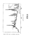
- FIG. 2 is a view showing an example of the emission spectrum of the measurement subject 2.
- the atomic spectral lines (spectral lines) are formed superimposed on the continuous optical component. Consequently, if the optical intensity ratio calculation section 11 were to attempt to calculate the intensity ratio of the atomic spectral lines simply utilizing the intensity of the light having the wavelengths of the atomic spectral lines, it would be unable to calculate the intensity ratio of the atomic spectral lines accurately, because of this continuous optical component.
- the optical intensity ratio calculation section 11 calculates the intensity ratio of the atomic spectral lines, removing the intensity of the continuous optical component. Specifically, the optical intensity ratio calculation section 11 calculates the intensity of the atomic spectral lines emitted from the measurement location of the measurement subject 2, subtracting the intensity of the continuous optical component from the intensity of the light having the wavelengths of the atomic spectral lines. Specifically, since the light having the wavelength ⁇ c is light of a wavelength region where there are no atomic spectral lines, the intensity of the light having the wavelength ⁇ c is the intensity of the continuous optical component.
- the optical intensity ratio calculation section 11 is able to calculate the intensities of the atomic spectral lines emitted by the measurement subject 2.
- the optical intensity ratio calculation section 11 calculates the intensity ratio of the atomic spectral lines emitted by the measurement location of the measurement subject 2, from the calculated intensities of the atomic spectral lines.
- the calibration section 9a calculates the intensity (IA) of the light having the wavelength ⁇ a and supplies information indicating the calculated intensity to the optical intensity ratio calculation section 11.
- the intensity indicated by the information supplied by the calibration section 9a is the intensity in a condition in which the continuous optical component is added to the atomic spectral lines emitted by the measurement subject 2.
- the calibration section 9c calculates the intensity (IC) of the light having the wavelength ⁇ c, and supplies information indicating this calculated intensity to the optical intensity ratio calculation section 11.
- the wavelength ⁇ c is not any of the atomic spectral line wavelengths, so the intensity indicated by the information supplied by the calibration section 9a is the intensity of the continuous optical component.
- the optical intensity ratio calculation section 11 may be a computation circuit and may be constituted for example by a PC.
- the optical intensity ratio calculation section 11 is electrically connected with a temperature calculation section 15.
- the optical intensity ratio calculation section 11 transmits information indicating the calculated intensity ratio of the atomic spectral lines to the temperature calculation section 15.
- the temperature calculation section 15 calculates the temperature of the measurement location of the measurement subject 2, based on the information indicating the intensity ratio of the atomic spectral lines that is delivered by the optical intensity ratio calculation section 11.
- the temperature calculation section 15 can calculate the temperature of the measurement location of the measurement subject 2 by substituting the intensity ratio (In/Im) of the atomic spectral lines in Expression (1).
- the temperature calculation section 15 may be for example a PC. Also, the temperature calculation section 15 may comprise for example a display section that displays the calculated temperature. The temperature calculation section 15 may also comprise for example a transmission section that transmits information indicating the calculated temperature to another device.
- optical intensity ratio calculation section and the temperature calculation section 15 may also be constituted by a single PC.
- the calibration sections 9, the optical intensity ratio calculation section 11 and the temperature calculation section 15 may be constituted by a single PC.
- the construction of the various sections is not restricted to a specific construction.
- a measurement subject 2 is generated within an individual container 1.
- the user of the temperature measurement device 20 may cause a measurement subject 2 constituted by a plasma, explosion, or chemical reaction or the like to be generated within the individual container 1.
- the optical input section 3 collects the emission spectrum that is emitted by the measurement subject 2 at a measurement location separated by a focal point distance 13 from the optical input section 3. On collecting the emission spectrum that is emitted by the measurement subject 2 at the measurement location, the optical input section 3 supplies this collected emission spectrum to the amount of light adjustment section 6 by the transmission path 5.
- the amount of light adjustment section 6 supplies the emission spectrum that is supplied by the optical input section 3 by the transmission path 5. When this emission spectrum is supplied thereto, the amount of light adjustment section 6 adjusts the amount of light of the supplied emission spectrum. On adjusting the amount of light of the emission spectrum, the amount of light adjustment section 6 supplies the emission spectrum, whose amount of light has thus been adjusted, to the wavelength selection section 7 by the transmission path 5.
- the wavelength selection section 7 supplies the emission spectrum that has been supplied thereto by the amount of light adjustment section 6 by the transmission path 5. On being thus supplied with the emission spectrum, the wavelength selection section 7 extracts optical components having the wavelengths ⁇ a, ⁇ b and ⁇ c from this thus-supplied emission spectrum. On extracting the optical components having the wavelengths ⁇ a, ⁇ b and ⁇ c, the wavelength selection section 7 supplies to the respective detectors 8a, 8b and 8c light having the wavelengths ⁇ a, ⁇ b and ⁇ c, by the transmission path 5.
- the detectors 8a, 8b and 8c are supplied light of the respective wavelengths ⁇ a, ⁇ b and ⁇ c, by the transmission path 5.
- the detectors 8a, 8b and 8c convert the light with which they are respectively supplied to voltages.
- the detectors 8a, 8b and 8c supply the voltages that are thereby generated respectively to the calibration sections 9a, 9b and 9c.
- the calibration sections 9a, 9b and 9c are respectively supplied with voltages obtained by conversion from light by the detectors 8a, 8b and 8c. When they are thus supplied with these voltages, the calibration sections 9a, 9b and 9c calculate the intensities of the light supplied to the respective detectors 8a, 8b and 8c, based on these supplied voltages. On thus calculating the optical intensities, the calibration sections 9a, 9b and 9c transmit to the optical intensity ratio calculation section 11 information indicating the intensities of the light having the respective wavelengths ⁇ a, ⁇ b and ⁇ c.
- the optical intensity ratio calculation section 11 receives this information indicating the intensities of the light having the wavelengths ⁇ a, ⁇ b and ⁇ c. On receiving these items of information, the optical intensity ratio calculation section 11 calculates the intensity ratio of the atomic spectral lines emitted by the measurement location of the measurement subject 2, based on these items of information. On calculating the intensity ratio of the atomic spectral lines, the optical intensity ratio calculation section 11 transmits to the temperature calculation section 15 information indicating the intensity ratio of the calculated atomic spectral lines.
- the temperature calculation section 15 receives the information indicating the intensity ratio of the atomic spectral lines calculated by the optical intensity ratio calculation section 11. On receiving this information indicating the intensity ratio of the atomic spectral lines, the temperature calculation section 15 calculates the temperature of the measurement location in accordance with Expression (1). On calculating the temperature of the measurement location, the temperature calculation section 15 presents information indicating the temperature of the measurement location to the outside. For example, in the case where the temperature calculation section 15 comprises a display section, the temperature calculation section 15 displays the temperature of the measurement location on the display section. Also, if the temperature calculation section 15 comprises a transmission section, the temperature calculation section 15 transmits information indicating the temperature of the measurement location to another device through the transmission section.
- the temperature measurement device 20 terminates the temperature measurement operation when the temperature calculation section 15 presents the information indicating the temperature of the measurement location to the outside.
- the temperature measurement device 20 may also measure the intensity of light having two wavelengths, namely, wavelength ⁇ c and wavelength ⁇ d, from the wavelength region where there are no atomic spectral lines.
- the wavelength ⁇ c may be close to the wavelength ⁇ a, while the wavelength ⁇ d is close to the wavelength ⁇ b.
- the light having the wavelength ⁇ c is the continuous optical component in the vicinity of light having the wavelength ⁇ a. Consequently, the intensity of the light having the wavelength ⁇ c is close to the intensity of the continuous optical components of the light having the wavelength ⁇ a.
- the temperature measurement device 20 can calculate the intensity of the atomic spectral line having the wavelength ⁇ a that is emitted by the measurement location of the measurement subject 2 more accurately.
- the temperature measurement device 20 can calculate the intensity of the atomic spectral line having the wavelength ⁇ b emitted by the measurement location of the measurement subject 2 more accurately.
- the temperature measurement device 20 may infer the intensity of the continuous optical component having the wavelength ⁇ a by measuring the intensity of the continuous optical component in the vicinity of the wavelength ⁇ a for a plurality of points.
- the temperature measurement device 20 may infer the intensity of the continuous optical component having the wavelength ⁇ b by measuring the intensity of the continuous optical component in the vicinity of the wavelength ⁇ b for a plurality of points.
- the number of points of the continuous optical component whose intensity is measured by the temperature measurement device 20 is not restricted to a specified number.
- a temperature measurement device 20 constructed as described above can accurately measure the intensity of the atomic spectral lines emitted by the measurement location of the measurement subject, by removing the continuous optical component having the wavelengths of the atomic spectral lines. In this way, the temperature measurement device 20 can accurately calculate the intensity ratio of the atomic spectral lines emitted by the measurement location of the measurement subject, and, as a result, can accurately calculate the temperature of the measurement location of the measurement subject.
- a temperature measurement device differs from the temperature measurement device 20 according to the first embodiment in that the temperature of the measurement subject 2 is measured based on the intensities of three or more atomic spectral lines emitted by the measurement subject 2 and the intensity of an optical component having a wavelength other than the wavelength of these atomic spectral lines. Accordingly, a detailed description concerning other aspects thereof may be dispensed with.
- the temperature measurement device calculates the temperature of the measurement subject 2, based on the intensity ratio of a pair of two or more atomic spectral lines.
- the temperature measurement device calculates the intensity ratio from two atomic spectral lines (spectral line pair) of copper and calculates the intensity ratio from two atomic spectral lines of fluorine.
- the temperature measurement device calculates the temperature of the measurement subject 2 from the intensity ratio of an atomic spectral line pair of copper and the intensity ratio of an atomic spectral line pair of fluorine. This is described in detail below.
- FIG. 3 is a view showing diagrammatically an example layout of a temperature measurement device 30 according to the second embodiment.
- the temperature measurement device 30 additionally comprises detectors 8d and 8e and calibration sections and calibration sections 9d and 9e.
- the detectors 8d and 8e are optically connected with the wavelength selection section 7 through the transmission path 5.
- the calibration sections 9d and 9e are respectively electrically connected with the detectors 8d and 8e. Also, the calibration sections 9d and 9e are electrically connected with the optical intensity ratio calculation section 11.
- the wavelength selection section 7 extracts light of the wavelengths of three or more atomic spectral lines and light having a single wavelength in a wavelength region where there are no atomic spectral lines.
- the wavelength selection section 7 extracts light having the wavelength ⁇ a and the wavelength ⁇ b of two atomic spectral lines of copper (Cu), the wavelength ⁇ c and the wavelength ⁇ d of two atomic spectral lines of fluorine (F), and a single wavelength ⁇ e in a wavelength region where there are no atomic spectral lines.
- the wavelength selection section 7 supplies light having the extracted wavelengths ⁇ a to ⁇ e to the respective detectors 8a to 8e.
- the detectors 8a to 8e convert the light which is thus supplied to voltages.
- the detectors 8a to 8e supply these voltages, obtained by conversion of the supplied light, to the respective calibration sections 9a to 9e. From the supplied voltages, the calibration sections 9a to 9e calculate the intensity of the light supplied to the detectors 8 by the wavelength selection section 7.
- the calibration section 9a supplies information indicating the intensity (IA) of light having the wavelength ⁇ a to the optical intensity ratio calculation section 11.
- the calibration section 9b supplies information indicating the intensity (IB) of light having the wavelength ⁇ b to the optical intensity ratio calculation section 11.
- the calibration section 9c supplies information indicating the intensity (IC) of light having the wavelength ⁇ c to the optical intensity ratio calculation section 11.
- the calibration section 9d supplies information indicating the intensity (ID) of light having the wavelength ⁇ d to the optical intensity ratio calculation section 11.
- the calibration section 9e supplies information indicating the intensity (IE) of light having the wavelength ⁇ b to the optical intensity ratio calculation section 11.
- the optical intensity ratio calculation section 11 receives the information indicating the intensities (IA to IE) of the light having the wavelengths ⁇ a to ⁇ e. On receiving these items of information, the optical intensity ratio calculation section 11 calculates the intensity ratio of the atomic spectral line pair of copper and the intensity ratio of the atomic spectral line pair of fluorine. The calculation procedure is described below.
- the optical intensity ratio calculation section 11 On calculating the intensity ratio of the atomic spectral line pair of copper and the intensity ratio of the atomic spectral line pair of fluorine, the optical intensity ratio calculation section 11 transmits information indicating the intensity ratio of the atomic spectral line pair of copper and information indicating the intensity ratio of the atomic spectral line pair of fluorine to the temperature calculation section 15.
- the temperature calculation section 15 receives these items of information. On receiving these items of information, the temperature calculation section 15 calculates the temperature of the measurement location of the measurement subject 2, based on the intensity ratio of the atomic spectral line pair of copper and the intensity ratio of the atomic spectral line pair of fluorine. The procedure of calculation of the temperature by the temperature calculation section 15 is described below.
- the temperature calculation section 15 determines the intensity ratio of the atomic spectral line pair to be employed for calculation of the temperature. Specifically, the temperature calculation section 15 determines the intensity ratio of the atomic spectral line pair that is most suitable for the calculation of the temperature.
- FIG. 4 is a view showing the relationship of intensity and temperature of the atomic spectral lines of copper and the relationship of intensity and temperature of the atomic spectral lines of fluorine, based on logical values.
- the temperature measurement device 30 In the temperature region that is sought to be measured by the temperature measurement device 30, if the change of the calculated temperature with respect to the change of the intensity ratio of the atomic spectral line pair is excessively large or excessively small, the temperature measurement device 30 is unable to calculate the temperature accurately. For example, if the calculated change of temperature is excessively large with respect to the change in the intensity ratio of the atomic spectral line pair, the temperature measurement device 30 is unable to calculate the temperature accurately even if slight noise is generated in the intensity ratio of the atomic spectral line pair.
- the temperature measurement device 30 finds it difficult to calculate the precise temperature without requiring accurate measurement of the intensity ratio of the atomic spectral line pair up to high values (for example at least 10).
- a temperature region in which temperature can be accurately measured by employing the intensity ratio of an atomic spectral line pair is constituted by a temperature region (appropriate temperature measurement range) such that the change in the calculated temperature corresponding to change in the intensity ratio of this atomic spectral line pair is within a fixed range.
- a temperature region appropriate temperature measurement range
- Such an appropriate temperature measurement range is determined in accordance with for example the system or measurement conditions required for measurement.
- the appropriate temperature measurement range may be defined as a temperature region that satisfies the following expression. [Math 2] 1000 ⁇ dT / d I n I m ⁇ 2000
- the range satisfying Expression (2) is roughly 6000 K to 10,000 K. Also, in the relationship of intensity ratio and temperature of an atomic spectral line pair of fluorine, the range satisfying Expression (2) is roughly 2000 K to 4000 K. Consequently, if the temperature of the measurement location of the measurement subject 2 is roughly 2000 K to 4000 K, the temperature measurement device 30 calculates the temperature using the intensity ratio of the atomic spectral line pair of fluorine. Also, if the temperature of the measurement location of the measurement subject 2 is roughly 6000 K to 10,000 K, the temperature measurement device 30 calculates the temperature using the intensity ratio of the atomic spectral line pair of copper.
- the temperature calculation section 15 calculates respective temperatures of the measurement location of the measurement subject 2 based on the intensity ratio of the atomic spectral line pair of copper and the intensity ratio of the atomic spectral line pair of fluorine.
- the temperature calculation section 15 decides on the atomic spectral line pair whose intensity ratio is to be used for temperature calculation as being the atomic spectral line pair in respect of which the temperature that is calculated therefrom falls within the appropriate temperature measurement range.
- the temperature calculation section 15 identifies the intensity ratio of the atomic spectral lines in question as being the intensity ratio of the atomic spectral line pair that is to be used for temperature calculation. For example, if the temperature calculation section 15 calculates the temperature of the measurement location, from the intensity ratio of the atomic spectral line pair of copper, as 7000 K (in other words, within the appropriate temperature measurement range of the atomic spectral line pair of copper), the temperature calculation section 15 identifies the intensity ratio of the atomic spectral line pair of copper as being the intensity ratio of the atomic spectral line pair that is to be used for temperature calculation.
- the temperature calculation section 15 designates the temperature calculated from the intensity ratio of this atomic spectral line pair as the temperature of the measurement location of the measurement subject 2. Once it has determined the temperature of the measurement location of the measurement subject 2, the temperature calculation section 15 presents information indicating the temperature of the measurement location to the outside. When this information indicating the temperature of the measurement location has been presented to the outside, the temperature measurement device 30 terminates the temperature measurement operation.
- the temperature measurement device 30 may then measure the intensity of the light at a plurality of points in a wavelength region where there are no atomic spectral lines, and calculate the intensity of the atomic spectral lines emitted from the measurement location of the measurement subject 2 from these measured intensities.
- the intensity ratio of a plurality of atomic spectral line pairs of different appropriate temperature measurement ranges can be changed over in accordance with the temperature of the measurement subject.
- the temperature measurement device 30 can select the intensity ratio of the atomic spectral line pair in accordance with the temperature measurement range and thus measure the temperature of the measurement subject more accurately. Also, with this temperature measurement device 30, an expanded temperature measurement region can be achieved.
- This temperature measurement device differs from the temperature measurement device according to the first embodiment in which a cover is arranged at the tip of the optical input section 3. A detailed description of other aspects may therefore be omitted.
- FIG. 5 is a view showing diagrammatically an example layout of a temperature measurement device 40 according to the third embodiment.
- the temperature measurement device 40 comprises a cover 14 that is arranged at the tip of the optical input section 3.
- the cover 14 is provided so that the optical input section 3 collects only the emission spectrum of the measurement location of the measurement subject 2.
- the cover 14 prevents light that is emitted for example from the measurement subject 2 or individual container 1 from locations further than the focal point distance 13 from being directed onto the optical input section 3. In this way, the optical input section 3 can collect the emission spectrum of the measurement location of the measurement subject 2 with better definition.
- the cover 14 may be tubular, with openings at the top and bottom of the cover 14. Thanks to the openings at the top and bottom of the cover 14, measurement subjects 2 can flow smoothly into the interior of the cover 14. In this way, the cover 14 can prevent to the utmost degree disturbance of the flow of the measurement subjects 2.
- the cover 14 is provided, in its side face, with a hole for installation of the optical input section 3.
- the hole that is provided in the cover 14 passes through the side face of the cover 14.
- the tip of the optical input section 3 is fixed in the hole provided in the cover 14. In this way, the optical input section 3 can collect light from the interior of the cover 14. It should be noted that the tip of the optical input section 3 may or may not project into the interior of the cover 14.
- the diameter of the cover 14 is slightly larger than the focal point distance 13 of a lens that is arranged in the optical input section 3. In this way, the optical input section 3 can collect the emission spectrum of a measurement location that is separated by the focal point distance 13 in the interior of the cover 14. Also, the cover 14 prevents the optical input section 3 from collecting light emitted by measurement subjects 2 that are further away than the focal point distance 13.
- the interior of the cover 14 is processed as a specular surface.
- the physical properties produced by this specular processing mean that the light that is emitted therefrom shows little change with change of temperature. Consequently, the cover 14 does not readily emit light that changes with change in temperature.
- the optical input section 3 can collect the emission spectrum of the measurement location without any possibility of collecting light emitted as a result of change of temperature of the cover 14.
- the cover 14 has strength capable of withstanding for example shock or heat generated by the measurement subjects 2.
- the cover 14 may be formed of metal or the like, but there is no specific restriction regarding the physical properties of the cover 14.
- the third embodiment may also comprise the characteristic features of the second embodiment.
- the cover 14 need not be of tubular shape.
- the shape of the cover 14 is not restricted to being a specific shape, so long as it is a shape whereby the light that is collected by the optical input section 3 is restricted to the emission spectrum generated by the measurement location of the measurement subject 2.
- a temperature measurement device 40 constructed as described above is capable of collecting the emission spectrum of the measurement location of the measurement subject with even better definition. Consequently, the temperature measurement device 40 can calculate the temperature of the measurement location of the measurement subject even more accurately. Also, the temperature measurement device 40 can calculate the temperature of the measurement location of the measurement subject while disturbing to the least degree possible the flow of the measurement subjects.
Landscapes
- Physics & Mathematics (AREA)
- General Physics & Mathematics (AREA)
- Spectroscopy & Molecular Physics (AREA)
- Radiation Pyrometers (AREA)
- Investigating Or Analysing Materials By Optical Means (AREA)
- Measuring And Recording Apparatus For Diagnosis (AREA)
- Investigating, Analyzing Materials By Fluorescence Or Luminescence (AREA)
Applications Claiming Priority (1)
| Application Number | Priority Date | Filing Date | Title |
|---|---|---|---|
| JP2013019295A JP6100005B2 (ja) | 2013-02-04 | 2013-02-04 | 温度測定装置 |
Publications (2)
| Publication Number | Publication Date |
|---|---|
| EP2762846A2 true EP2762846A2 (de) | 2014-08-06 |
| EP2762846A3 EP2762846A3 (de) | 2018-03-28 |
Family
ID=50023487
Family Applications (1)
| Application Number | Title | Priority Date | Filing Date |
|---|---|---|---|
| EP14153517.9A Withdrawn EP2762846A3 (de) | 2013-02-04 | 2014-01-31 | Temperaturmessvorrichtung |
Country Status (4)
| Country | Link |
|---|---|
| US (1) | US9494466B2 (de) |
| EP (1) | EP2762846A3 (de) |
| JP (1) | JP6100005B2 (de) |
| CN (1) | CN103968955B (de) |
Families Citing this family (7)
| Publication number | Priority date | Publication date | Assignee | Title |
|---|---|---|---|---|
| US10161799B2 (en) * | 2015-02-25 | 2018-12-25 | The University Of Tokyo | Temperature measuring device and temperature measuring method |
| DE102015217633A1 (de) * | 2015-09-15 | 2017-03-16 | Siemens Aktiengesellschaft | Vorrichtung zur Erkennung eines Störlichtbogens und elektrische Schaltanlage |
| CN105784121B (zh) * | 2016-04-01 | 2018-10-26 | 华北电力大学 | 九通道自适应大范围二维温度场测量装置及其测量方法 |
| US10760969B1 (en) * | 2019-02-28 | 2020-09-01 | Biospex, Inc. | Fluorescence and systemic noise reduction in time-gated spectroscopy |
| US11326944B2 (en) | 2019-07-12 | 2022-05-10 | Biospex, Inc. | Wearable spectrometer with filtered sensor |
| US11454540B2 (en) | 2019-07-12 | 2022-09-27 | Biospex, Inc. | Wearable spectroscopy using filtered sensor |
| CN112284566B (zh) * | 2020-10-10 | 2023-02-28 | 哈尔滨工业大学 | 一种基于深度学习的超声速燃烧室温度测量装置及其测量方法 |
Family Cites Families (16)
| Publication number | Priority date | Publication date | Assignee | Title |
|---|---|---|---|---|
| JPS54111874A (en) * | 1978-02-21 | 1979-09-01 | Kobe Steel Ltd | Method and device for measuring temperature of arc |
| JPH02173531A (ja) * | 1988-12-26 | 1990-07-05 | Mitsubishi Electric Corp | 赤外線検出装置 |
| JPH02195234A (ja) * | 1989-01-24 | 1990-08-01 | Shimadzu Corp | 電子温度分布測定装置 |
| US5408314A (en) * | 1993-02-24 | 1995-04-18 | Perry; Jeffrey | Dark current subtraction with abbreviated reference cycles and recursive filtering |
| US6780657B2 (en) * | 1998-03-19 | 2004-08-24 | Kabushiki Kaisha Toshiba | Temperature measuring method and apparatus, measuring method for the thickness of the formed film, measuring apparatus for the thickness of the formed film thermometer for wafers |
| JP2001165857A (ja) * | 1999-12-10 | 2001-06-22 | Shimadzu Corp | Icp発光分光分析装置 |
| JP2002022541A (ja) * | 2000-07-06 | 2002-01-23 | Central Res Inst Of Electric Power Ind | アーク放電の温度および金属蒸気混入率の同時測定法 |
| US6914246B2 (en) * | 2003-03-27 | 2005-07-05 | Gas Technology Institute | Method and apparatus for spatially resolving flame temperatures using ultraviolet light emission |
| JP4436262B2 (ja) * | 2005-02-09 | 2010-03-24 | 三菱重工業株式会社 | 微量成分計測装置 |
| JP4662360B2 (ja) * | 2005-12-26 | 2011-03-30 | 三菱重工環境・化学エンジニアリング株式会社 | プラズマ溶融炉におけるスラグ温度計測方法及び装置 |
| DE102006045578B3 (de) * | 2006-09-25 | 2008-02-14 | Deutsches Zentrum für Luft- und Raumfahrt e.V. | Verfahren zur Standardisierung der Ableitung der Temperatur in der Mesopausenregion aus Hydroxyl (OH*)-Airglow |
| WO2008059598A1 (fr) * | 2006-11-17 | 2008-05-22 | Imagineering, Inc. | Dispositif d'analyse de réaction, support d'enregistrement et système de mesure |
| CN201096521Y (zh) * | 2007-11-06 | 2008-08-06 | 南京理工大学 | 非接触式等离子体温度和电子密度测量装置 |
| US20100309463A1 (en) * | 2009-06-04 | 2010-12-09 | Robert Lucke | Specular integrating tube for scattered-light spectroscopy |
| JP2012208050A (ja) * | 2011-03-30 | 2012-10-25 | Tokyo Electron Ltd | 測定装置及びプラズマ処理装置 |
| WO2015068048A1 (en) * | 2013-11-11 | 2015-05-14 | King Abdullah University Of Science And Technology | High repetition rate thermometry system and method |
-
2013
- 2013-02-04 JP JP2013019295A patent/JP6100005B2/ja not_active Expired - Fee Related
-
2014
- 2014-01-31 US US14/169,651 patent/US9494466B2/en not_active Expired - Fee Related
- 2014-01-31 EP EP14153517.9A patent/EP2762846A3/de not_active Withdrawn
- 2014-02-07 CN CN201410044846.5A patent/CN103968955B/zh not_active Expired - Fee Related
Non-Patent Citations (1)
| Title |
|---|
| TAKEUCHI ET AL.: "Temperature and Metal Vapor Near the Cathode in Copper Breaking Arcs According to Spectroscopic Measurement", IEEE TRANSACTIONS ON PLASMA SCIENCE, vol. 28, no. 3, 2000, pages 991 - 999 |
Also Published As
| Publication number | Publication date |
|---|---|
| US20140219312A1 (en) | 2014-08-07 |
| CN103968955B (zh) | 2017-01-11 |
| JP6100005B2 (ja) | 2017-03-22 |
| US9494466B2 (en) | 2016-11-15 |
| EP2762846A3 (de) | 2018-03-28 |
| CN103968955A (zh) | 2014-08-06 |
| JP2014149263A (ja) | 2014-08-21 |
Similar Documents
| Publication | Publication Date | Title |
|---|---|---|
| US9494466B2 (en) | Temperature measurement device | |
| JP4829995B2 (ja) | 電荷結合素子検出器を有する発光分光計 | |
| Gardner et al. | A wide-field k-band survey: The luminosity function of galaxies | |
| Smeets | Laser interferometer for high sensitivity measurements on transient phase objects | |
| JPWO2003073127A1 (ja) | 気象観測ライダーシステム | |
| US10337986B2 (en) | Method for optimisation of detection wavelengths for multi-gas detection | |
| JP2010528296A (ja) | 温度及び化学種濃度の高空間分解能測定のためのビニング及び断層撮影法 | |
| US5667304A (en) | Mesospheric temperature sensing lidar apparatus | |
| Mansmann et al. | Detector calibration and measurement issues in multi-color time-resolved laser-induced incandescence: R. Mansmann et al. | |
| US6756593B2 (en) | Flame Sensor | |
| US7675618B2 (en) | Multiplexing spectrometer | |
| US6329660B1 (en) | Method of deriving sunlight induced fluorescence from radiance measurements and devices for executing the method | |
| Duquette et al. | Absolute transition probabilities in NbI and Hfl and a solution to the problem of missing infrared branches | |
| CN119860845A (zh) | 光谱装置和光谱标定与探测方法 | |
| CN119716431A (zh) | 一种基于三元颜色空间的绝缘子放电检测方法、系统及装置 | |
| CN103063324B (zh) | 分子气体激光器腔内气体温度监控装置及其方法 | |
| JP2002521656A (ja) | 分光計の機能を試験する方法および故障検出装置を有する分光計 | |
| EP3850343B1 (de) | Vorrichtung zur analyse der materialzusammensetzung einer probe mittels plasmaspektralanalyse | |
| RU2366909C1 (ru) | Многоканальное устройство для измерения пирометрических характеристик | |
| Souaidia et al. | Comparison of laser-based and conventional calibrations of sun photometers | |
| CN108303387B (zh) | 用于分析测量区域的方法和微型光谱仪 | |
| RO137925A0 (ro) | Metodă şi aparat pentru validarea in-field a etalonării în radianţă şi iradianţă spectrală a sistemelor spectroradiometrice cu optică dublă având rezoluţie spectrală ridicată, utilizate pentru monitorizarea vegetaţiei | |
| JP2004037192A (ja) | フォトダイオードアレイ分光分析装置 | |
| JPH07229948A (ja) | 不良碍子検出方法及び不良碍子検出器 | |
| Zhang et al. | Design of silicon ring resonators for CO 2 detection |
Legal Events
| Date | Code | Title | Description |
|---|---|---|---|
| PUAI | Public reference made under article 153(3) epc to a published international application that has entered the european phase |
Free format text: ORIGINAL CODE: 0009012 |
|
| 17P | Request for examination filed |
Effective date: 20140131 |
|
| AK | Designated contracting states |
Kind code of ref document: A2 Designated state(s): AL AT BE BG CH CY CZ DE DK EE ES FI FR GB GR HR HU IE IS IT LI LT LU LV MC MK MT NL NO PL PT RO RS SE SI SK SM TR |
|
| AX | Request for extension of the european patent |
Extension state: BA ME |
|
| RIC1 | Information provided on ipc code assigned before grant |
Ipc: G01J 5/60 20060101AFI20171115BHEP Ipc: G01K 11/12 20060101ALI20171115BHEP Ipc: G01J 5/06 20060101ALI20171115BHEP Ipc: G01J 5/00 20060101ALI20171115BHEP Ipc: G01J 5/08 20060101ALI20171115BHEP |
|
| PUAL | Search report despatched |
Free format text: ORIGINAL CODE: 0009013 |
|
| AK | Designated contracting states |
Kind code of ref document: A3 Designated state(s): AL AT BE BG CH CY CZ DE DK EE ES FI FR GB GR HR HU IE IS IT LI LT LU LV MC MK MT NL NO PL PT RO RS SE SI SK SM TR |
|
| AX | Request for extension of the european patent |
Extension state: BA ME |
|
| RIC1 | Information provided on ipc code assigned before grant |
Ipc: G01J 5/08 20060101ALI20180221BHEP Ipc: G01J 5/00 20060101ALI20180221BHEP Ipc: G01K 11/12 20060101ALI20180221BHEP Ipc: G01J 5/06 20060101ALI20180221BHEP Ipc: G01J 5/60 20060101AFI20180221BHEP |
|
| STAA | Information on the status of an ep patent application or granted ep patent |
Free format text: STATUS: THE APPLICATION HAS BEEN WITHDRAWN |
|
| 18W | Application withdrawn |
Effective date: 20180508 |