EP2762741A2 - Accouplement à membrane - Google Patents
Accouplement à membrane Download PDFInfo
- Publication number
- EP2762741A2 EP2762741A2 EP14150206.2A EP14150206A EP2762741A2 EP 2762741 A2 EP2762741 A2 EP 2762741A2 EP 14150206 A EP14150206 A EP 14150206A EP 2762741 A2 EP2762741 A2 EP 2762741A2
- Authority
- EP
- European Patent Office
- Prior art keywords
- membrane
- coupling
- disc
- membrane coupling
- fibers
- Prior art date
- Legal status (The legal status is an assumption and is not a legal conclusion. Google has not performed a legal analysis and makes no representation as to the accuracy of the status listed.)
- Granted
Links
Images


Classifications
-
- F—MECHANICAL ENGINEERING; LIGHTING; HEATING; WEAPONS; BLASTING
- F16—ENGINEERING ELEMENTS AND UNITS; GENERAL MEASURES FOR PRODUCING AND MAINTAINING EFFECTIVE FUNCTIONING OF MACHINES OR INSTALLATIONS; THERMAL INSULATION IN GENERAL
- F16D—COUPLINGS FOR TRANSMITTING ROTATION; CLUTCHES; BRAKES
- F16D3/00—Yielding couplings, i.e. with means permitting movement between the connected parts during the drive
- F16D3/50—Yielding couplings, i.e. with means permitting movement between the connected parts during the drive with the coupling parts connected by one or more intermediate members
- F16D3/72—Yielding couplings, i.e. with means permitting movement between the connected parts during the drive with the coupling parts connected by one or more intermediate members with axially-spaced attachments to the coupling parts
- F16D3/725—Yielding couplings, i.e. with means permitting movement between the connected parts during the drive with the coupling parts connected by one or more intermediate members with axially-spaced attachments to the coupling parts with an intermediate member made of fibre-reinforced resin
Definitions
- the invention relates to a diaphragm coupling for transmitting a torque and for compensating for axial, radial and / or angular misalignment between input and output elements with a tubular hub and with a front end subsequent membrane disk, wherein the hub and the membrane disk made of a fiber-reinforced plastic material.
- Diaphragm couplings are often used in various areas of drive technology in order to transmit the highest possible torque between drive elements and output elements, which may have an axial offset, a radial offset or an angular offset.
- a slight deviation from the ideal alignment relative to one another can often not be ruled out.
- an axial or radial offset or angular offset between adjacent drive or output elements can hardly be avoided.
- the individual input or output elements can also change the position and orientation relative to each other dynamically by vibrations and radially acting loads in a transition region. An unavoidable misalignment of adjacent input and output elements during operation must be ensured by suitable membrane couplings can be compensated for the longest possible service life.
- the membrane couplings have the smallest possible wall thickness of the membrane disc in order to be as flexible as possible and to ensure a stress-free compensation of axial relative movements to each other and angular differences associated with the diaphragm coupling drive or output elements.
- a thin membrane disc has not only an advantageous low bending stiffness, but also a low buckling stiffness, whereby the maximum transmissible torque is limited.
- a low buckling stiffness can lead to a sudden failure of the diaphragm coupling under excessive load.
- membrane couplings are usually designed so that as reliably as possible a sufficient buckling stiffness is ensured, with necessarily a concomitant consequence of a comparatively large mass of the membrane coupling and a higher bending stiffness than required are accepted.
- diaphragm couplings made of a suitable fiber-plastic composite material can meet the requirements for the torque to be transmitted and the compensation of the expected axial and angular misalignment.
- Membrane couplings made of a fiber-plastic composite material also have the advantage of low weight and a correspondingly lower inert mass compared to membrane couplings made of metal.
- the membrane coupling should have advantageous damping properties.
- At least one reinforcing element is arranged on the membrane disc radially spaced from the hub and from an outer peripheral edge.
- the reinforcing element which is arranged radially in a central region between the hub and the outer edge, the available for buckling under load surface of the membrane disk or its radius is divided into at least two sections and thereby reduced respectively.
- the dent resistance of the membrane disc is increased.
- the membrane disk can be made substantially thinner than in the case of a membrane disk without an additional reinforcing element and the weight of the diaphragm coupling can be reduced.
- the reinforcing element considerably increases the buckling rigidity of the membrane disk, without significantly increasing the dead weight or unduly reducing the bending stiffness of the membrane coupling.
- the at least one reinforcing element can expediently be arranged approximately in the middle between the hub and the outer edge of the membrane disk, or the outer peripheral edge. In this middle range usually occurs little or no Bending stress of the membrane disc, so that the flexural rigidity is not significantly influenced or increased by the arranged in this central region reinforcing element.
- the at least one reinforcing element is arranged slightly closer to the hub or further outwards slightly closer to the outer peripheral edge.
- the bending stiffness and the buckling stiffness of the membrane coupling can be influenced in this way.
- the reinforcing element is an annular thickening of the membrane disc.
- An annular thickening is rotationally symmetrical and therefore allows uniform loading of the diaphragm coupling even at high speeds.
- An annular thickening can be produced precisely in a simple manner.
- annular thickening is formed on each side of the membrane disk.
- the annular thickenings may have an identical radial distance to the hub on both sides of the membrane disk. It is also conceivable that the annular thickenings on the opposite sides of the membrane disc each have a different radial distance to the hub, or to the outer peripheral edge of the membrane disc.
- the Beulsteifmaschine can be increased quite considerably with low material costs.
- a diaphragm of low mass, or a thin membrane disk of a fiber-reinforced plastic material is sufficient to transmit a high torque by a suitable design of the membrane disc. Due to the annular thickening, the buckling stiffness is increased even with comparatively thin membrane disks in such a way that membrane couplings with a very low inherent weight can fulfill the respective requirements for flexural rigidity, torque stability and buckling rigidity.
- the selection and arrangement of the fibers arranged in particular in the membrane disk can also influence the buckling rigidity and the damping properties of the membrane coupling.
- the incorporation of glass fibers can reduce manufacturing costs and, above all, improve the damping properties.
- the membrane disc has a carbon fiber reinforced inner region and a glass fiber reinforced outer region.
- the interior area which is particularly important for the buckling rigidity and the transmittable torque, is predominantly or completely with Carbon fibers reinforced, while the important for the damping properties outdoor area is reinforced with glass fibers.
- the proportion of reinforcing fibers per unit volume may be adjusted to the typically expected loads within the membrane disc. It is likewise conceivable to embed a first type of reinforcing fiber in the plastic matrix material over a large area and to additionally introduce a second type of reinforcing fiber in some areas.
- the membrane disk torque-transmitting fibers are incorporated, which have an orientation of approximately 45 ° to a radius line.
- the maximum transmissible torque is independent of the respective direction of rotation.
- the orientation of the torque-transmitting fibers can be optimized depending on the direction of rotation, so that another and in particular an asymmetrical orientation of the torque-transmitting fibers relative to the radius line is conceivable ,
- fibers are embedded in the membrane disk, the orientation of which differs significantly from a preferred for the torque transmission orientation of approximately 45 ° to a radius line. If the fiber orientation deviates from the dominant force and moment transmission direction, the forces and moments, but also shocks and pulses are transmitted essentially through the much more elastic plastic matrix material and not along the fibers, so that a stronger damping takes place.
- torque-transmitting fibers and differently oriented fibers may also be superimposed or interwoven in some regions or in all regions of the membrane disk.
- At least a predominant proportion of fibers is embedded in the membrane disk, which have an orientation between 45 ° and 90 ° to a radial line.
- the orientation and the respective proportions of the thus aligned fibers can be optimized and specified for each individual application. In many cases, an orientation at an angle of more than 45 ° and clearly less than 90 ° to a radial line will be expedient.
- the flexural stiffness, the maximum transmittable torque, and the damping properties through the selection and orientation of the individual fibers in the fiber-plastic composite material composing the membrane coupling can also be provided independently of the arrangement of a reinforcing element or the annular thickenings in membrane couplings be.
- Such a membrane coupling can be conveniently prepared by inserting and pressing prepregs in a tool.
- the orientation of the individual fibers which are embedded and arranged in the plastic matrix can be predetermined in a simple manner in that the membrane disk has a plurality of composite circular sector segments. Within a segment whose shape corresponds at least approximately to a circular sector segment, the orientation of the fibers is usually identical, so that the aforementioned preferred orientation of 45 ° or from an angle between 45 ° and 90 °, for example from about 70 ° to 85 ° in each case in regions is defined for a radius line running in the respective segment.
- the membrane disc when the membrane disc is made of several layers of circular prepregs which are stacked on top of each other and each have a unidirectional orientation of the reinforcing fibers over their entire surface. In each individual layer, the fibers have an identical orientation.
- a membrane disc can be made which in any direction, or at least for any radial lines in any case, the desired orientation of the fibers of at least one layer.
- a reinforcing element or optionally a plurality of reinforcing elements can be formed in a simple manner by the arrangement of a plurality of composite ring segments.
- the membrane disc consists of several seamlessly joined segments. In this way, local thickening or molding, as generated by partially overlapping segments, can be avoided. A complex post-processing of the membrane disk is then no longer necessary. Even at high speeds no imbalance arises.
- the membrane disk has at least one damping element.
- the damping element is a damping disc covering the membrane disc made of an elastic material.
- the damping disc can also be on both sides of each a diaphragm disc of a fiber-reinforced plastic material to be covered, on the one hand to protect the damping disk against excessive mechanical loads and on the other hand to allow the simplest possible connection of the diaphragm coupling to the adjacent in the axial direction of input and output elements.
- a first input or output element to be connected to a diaphragm disk on a first side of the damping disk in order to transmit torque, and a second input or output element to be torque-transmitting on the opposite side of the damping disk. In this way it is achieved that the torque can not be transmitted via a rigid component, but only by pushing and pulling forces acting through the damping disk through.
- the damping element is a longitudinally extending joint connection with an elastic material.
- the membrane disc can be composed, for example, of two rings, which also have an annular overlap region in the radial direction and are connected to one another with an elastic adhesive material.
- the elastic joint connection of the two rings simultaneously forms an annular thickening and thus a reinforcing element.
- the joint connection is a multi-section connection.
- the joint connection can be designed, for example, as a two-part connection, so that an annular formation or thickening is formed on both sides of the membrane disk.
- the membrane disk may be connected to the tubular hub by means of a damping joint connection.
- a separately manufactured rotationally symmetric angle element may be joined to the tubular hub in a first leg portion and to the membrane disc in a second leg portion.
- Advantage damping properties can be generated, or favored.
- a two-section connection of the membrane disc with the tubular hub can be achieved by the arrangement of a respective rotationally symmetrical angle element on both sides of an inner edge of the membrane disc and an end face of the tubular hub.
- the formation or arrangement of a damping element on the diaphragm coupling can also be independent of the arrangement of a reinforcing element or the annular thickening and regardless of the selection and orientation the reinforcing fibers may be provided in membrane couplings.
- An additionally required fastening flange for connecting the membrane coupling to input and output elements can be dispensed with, in that the membrane pane has recesses for connection to a drive or driven element along an outer peripheral edge.
- An attachment of the tubular hub of the diaphragm coupling to a hollow shaft can be accomplished in a simple manner that the hub of the diaphragm coupling has only a slight excess and is inserted at relatively low pressure in the axial direction in an end portion of the hub surrounding the hollow shaft. Subsequently, a mounting ring is pressed with a large oversize in the hub of the diaphragm coupling and presses the hub radially outward to the surrounding hollow shaft. Since the diaphragm coupling is introduced into the hollow shaft at a relatively low pressure, damage to the thin diaphragm disc during insertion and depression into the hollow shaft can be ruled out.
- the diaphragm coupling is already in the intended end position and no longer needs to be shifted or mechanically loaded, but only fixed in the intended end position with equally little effort to prevent slippage during the pressing of the mounting ring.
- the membrane coupling has two or more membrane disks arranged in parallel. Since the torque to be transmitted is distributed to both membrane discs, the membrane discs can be made substantially thinner. The thinner membrane discs then have a significantly lower flexural rigidity. The flexural rigidity of an assembly composed of two or more thinner membrane discs is significantly less than the flexural stiffness of a single thicker membrane disc, not only for the individual membrane discs, but also for a combination of the thinner membrane discs. Furthermore, the space required for the membrane coupling space can be significantly reduced. The two or more membrane discs may be coupled together via damping elements.
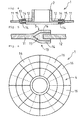
- a diaphragm coupling 1 which is integrally made of a fiber-reinforced plastic material.
- the membrane coupling 1 has a tubular hub 2 and a membrane disk 4 arranged on an end face 3 of the hub 2.
- an annular thickening 5 is formed, which forms a reinforcing element and considerably improves the buckling rigidity of the membrane disk 4, in spite of the small additional material.
- the annular thickening 5 is arranged on the membrane disk 4 radially approximately centrally between the hub 2 and an outer peripheral edge 6.
- the bending stress of the membrane disk 4 during the compensatory deformations during rotational movements is usually in a central region very low.
- the annular thickening 5 therefore hardly influences and increases the bending stiffness of the membrane disk 4.
- each outer side 7, 8 of the membrane disk 4 each have a rotationally symmetrical and thus annular thickening 9, 10 form.
- the two annular thickenings 9, 10 may have a different distance from the hub 2, or to the outer peripheral edge 6.
- the annular thickenings 9, 10 may also have different dimensions, or masses, so that specifically the BeulsteifIER, the flexural strength and the damping effect of the diaphragm coupling 1 can be influenced.
- the membrane disk 4 can be assembled by two annular disk-shaped membrane disk parts 11, 12, as shown schematically in the FIGS. 4 and 5 is shown.
- the outer membrane disk part 11 has glass fibers embedded in the plastic matrix material.
- the inner membrane disk part 12 has carbon fibers embedded in the plastic matrix material.
- the externally arranged membrane disk part 11 is divided in a connecting region 13 into two fastening tongues 14, which are the internally arranged membrane disk part 12 on both sides 7, 8 surrounds.
- the membrane disk part 11 is adhesively bonded with an elastic adhesive material 15 to the internally arranged membrane disk part 12. Due to the overlapping of the outer membrane disk part 11 with the inner membrane disk part 12 in the connection region 13, a two-sectioned connection and an annular thickening 5 are formed, which both acts as a reinforcing element and also has advantageous damping properties.
- the membrane disk 4 is made of a plurality of layers of prepregs 16 stacked in the axial direction.
- the circular segment prefabricated prepregs 16 are joined together seamlessly and each form a continuous, substantially gap-free composite layer.
- the joints of adjacent layers in the axial direction have an angular offset from each other, so that no continuous lines of weakness arise.
- the edges of an upper layer of circular segment-shaped prepregs 16 are in FIG. 6 shown by solid lines, while the edges of an underlying layer of prepregs 16 are indicated by dashed lines.
- FIG. 7 schematically a possible attachment of the diaphragm coupling 1 at an end portion 17 of a hollow shaft 18 and at an opposite mounting flange 19 is shown.
- the hollow shaft 18 and the mounting flange 19 are each part of a drive device, not shown.
- the hollow shaft 18 and the mounting flange 19 may be a dynamically changing during operation of the drive means axial offset and also have a dynamically changing angular offset relative to each other.
- the tubular hub 2 of the diaphragm coupling 1 only a slight excess to the hollow shaft 18, so that the outer diameter of the hub 2 only slightly larger than the inner diameter of the hollow shaft 18 is.
- the diaphragm coupling 1 can therefore be inserted with a comparatively small axially directed pressure into the end region 17 of the hollow shaft 18.
- diaphragm coupling 1 In order to fix the already arranged in the intended end position diaphragm coupling 1 relative to the hollow shaft 18 and set torque transmitting a fastening ring 20 is then inserted from the front side 3 forth in the hub 2, or pressed.
- the mounting ring 20 has a large excess to the hub 2 of the diaphragm coupling 1, so that the hub 2 is pressed by the mounting ring 20 radially outwardly to the surrounding end portion 17 of the hollow shaft 18 and thereby frictionally connected to the hollow shaft 18.
- the membrane disk 4 has a plurality of bores 21 along the outer peripheral edge 6 in the circumferential direction. Through the holes 21 through fastening bolts 22 can be inserted and screwed into matched blind holes 23 with a thread in the mounting flange 19 to set the membrane disk 4 to the mounting flange 19. It is not necessary for many applications that the diaphragm coupling 1 along the Outer peripheral edge 6 has its own mounting flange.
Landscapes
- Engineering & Computer Science (AREA)
- General Engineering & Computer Science (AREA)
- Mechanical Engineering (AREA)
- Diaphragms And Bellows (AREA)
- Shafts, Cranks, Connecting Bars, And Related Bearings (AREA)
Applications Claiming Priority (1)
| Application Number | Priority Date | Filing Date | Title |
|---|---|---|---|
| DE102013100946.8A DE102013100946A1 (de) | 2013-01-30 | 2013-01-30 | Membrankupplung |
Publications (3)
| Publication Number | Publication Date |
|---|---|
| EP2762741A2 true EP2762741A2 (fr) | 2014-08-06 |
| EP2762741A3 EP2762741A3 (fr) | 2016-02-24 |
| EP2762741B1 EP2762741B1 (fr) | 2018-07-11 |
Family
ID=49885151
Family Applications (1)
| Application Number | Title | Priority Date | Filing Date |
|---|---|---|---|
| EP14150206.2A Active EP2762741B1 (fr) | 2013-01-30 | 2014-01-06 | Accouplement à membrane |
Country Status (2)
| Country | Link |
|---|---|
| EP (1) | EP2762741B1 (fr) |
| DE (1) | DE102013100946A1 (fr) |
Cited By (2)
| Publication number | Priority date | Publication date | Assignee | Title |
|---|---|---|---|---|
| CN108016054A (zh) * | 2017-11-20 | 2018-05-11 | 刘长喜 | 碳纤维复合材料成型膜盘制造工艺 |
| EP3647619A1 (fr) * | 2018-10-29 | 2020-05-06 | Hamilton Sundstrand Corporation | Arbre d'entraînement composite assemblés de plusieurs pièces avec accouplements à soufflets |
Citations (3)
| Publication number | Priority date | Publication date | Assignee | Title |
|---|---|---|---|---|
| EP0064151A1 (fr) | 1981-04-30 | 1982-11-10 | Messerschmitt-Bölkow-Blohm Gesellschaft mit beschränkter Haftung | Accouplement pour arbre |
| EP0534927B1 (fr) | 1991-09-24 | 1995-12-06 | DR. ING. GEISLINGER & CO. SCHWINGUNGSTECHNIK GESELLSCHAFT m.b.H. | Pièce d'accouplement en matière plastique renforcée de fibres |
| US7568976B2 (en) | 2004-09-10 | 2009-08-04 | Centa-Antriebe Kirschey Gmbh | Rotary coupling |
Family Cites Families (3)
| Publication number | Priority date | Publication date | Assignee | Title |
|---|---|---|---|---|
| DE8514523U1 (de) * | 1985-05-14 | 1986-01-09 | Koehne, Wolfgang, 1000 Berlin | Gelenkwelle zur spielfreien Momentenübertragung mit elastischen Wellengelenken zum Ausgleich von Winkel- und Axialversatz |
| AT395901B (de) * | 1991-09-24 | 1993-04-26 | Geislinger Co Schwingungstechn | Kupplungsglied |
| CH688657A5 (de) * | 1994-11-14 | 1997-12-31 | Geislinger Co Schwingungstechn | Trockenkupplung. |
-
2013
- 2013-01-30 DE DE102013100946.8A patent/DE102013100946A1/de not_active Withdrawn
-
2014
- 2014-01-06 EP EP14150206.2A patent/EP2762741B1/fr active Active
Patent Citations (3)
| Publication number | Priority date | Publication date | Assignee | Title |
|---|---|---|---|---|
| EP0064151A1 (fr) | 1981-04-30 | 1982-11-10 | Messerschmitt-Bölkow-Blohm Gesellschaft mit beschränkter Haftung | Accouplement pour arbre |
| EP0534927B1 (fr) | 1991-09-24 | 1995-12-06 | DR. ING. GEISLINGER & CO. SCHWINGUNGSTECHNIK GESELLSCHAFT m.b.H. | Pièce d'accouplement en matière plastique renforcée de fibres |
| US7568976B2 (en) | 2004-09-10 | 2009-08-04 | Centa-Antriebe Kirschey Gmbh | Rotary coupling |
Cited By (3)
| Publication number | Priority date | Publication date | Assignee | Title |
|---|---|---|---|---|
| CN108016054A (zh) * | 2017-11-20 | 2018-05-11 | 刘长喜 | 碳纤维复合材料成型膜盘制造工艺 |
| EP3647619A1 (fr) * | 2018-10-29 | 2020-05-06 | Hamilton Sundstrand Corporation | Arbre d'entraînement composite assemblés de plusieurs pièces avec accouplements à soufflets |
| US11396904B2 (en) | 2018-10-29 | 2022-07-26 | Hamilton Sundstrand Corporation | Composite drive shafts |
Also Published As
| Publication number | Publication date |
|---|---|
| DE102013100946A1 (de) | 2014-07-31 |
| EP2762741A3 (fr) | 2016-02-24 |
| EP2762741B1 (fr) | 2018-07-11 |
Similar Documents
| Publication | Publication Date | Title |
|---|---|---|
| DE102013018261A1 (de) | Flexible Wellenkupplung und Verfahren zur Herstellung derselben | |
| DE102005055800A1 (de) | Vorrichtung zur Dämpfung von Torsionsschwingungen und Anordnung | |
| DE3710390A1 (de) | Elastische wellenkupplung | |
| DE102011109887A1 (de) | Wellenkupplung | |
| DE102008061588B4 (de) | Drehmomentübertragungseinrichtung mit blattfederartigen Elementen | |
| EP3280929A1 (fr) | Amortisseur d'oscillations pour chaîne cinématique | |
| DE102006049665B4 (de) | Kupplung für eine Kardanwelle | |
| DE3827249C2 (fr) | ||
| EP2762741B1 (fr) | Accouplement à membrane | |
| DE102009057914A1 (de) | Schwingungsdämpfer für einen Antriebsstrang | |
| EP2614265A1 (fr) | Arbre pour transmission de couples de rotation | |
| DE2415911B2 (de) | Verbindungsglied fuer drehelastische kupplungen | |
| DE102011014167A1 (de) | Wellenkupplung | |
| EP0498235B1 (fr) | Accouplement à membrane ajourée | |
| EP2201257B1 (fr) | Accouplement élastique d'arbres | |
| DE112008000697T5 (de) | Form zum Herstellen einer Verbundantriebswelle und unter Verwendung der Form hergestellte Verbundantriebswelle | |
| DE102015115913A1 (de) | Welleneinrichtung aus einem Faser-Kunststoff-Verbund | |
| EP0584821B1 (fr) | Accouplement élastique | |
| EP1479634B1 (fr) | Arbre, en particulier un arbre d'enroulement, avec des supports d'extrémité spéciaux | |
| DE2920074A1 (de) | Elastische kupplung | |
| DE102010053691A1 (de) | Elastisches Kupplungselement zur Verbindung von zwei Antriebswellen | |
| DE102011117298B4 (de) | Wellenkupplung | |
| EP3847383A1 (fr) | Disque de frein composite pour un frein à disque de véhicule | |
| EP2565480A1 (fr) | Elément mécanique de couplage ou d'embrayage | |
| DE202023102375U1 (de) | Räumlich-elastische Kupplung und Kupplungsanordnung |
Legal Events
| Date | Code | Title | Description |
|---|---|---|---|
| PUAI | Public reference made under article 153(3) epc to a published international application that has entered the european phase |
Free format text: ORIGINAL CODE: 0009012 |
|
| 17P | Request for examination filed |
Effective date: 20140106 |
|
| AK | Designated contracting states |
Kind code of ref document: A2 Designated state(s): AL AT BE BG CH CY CZ DE DK EE ES FI FR GB GR HR HU IE IS IT LI LT LU LV MC MK MT NL NO PL PT RO RS SE SI SK SM TR |
|
| AX | Request for extension of the european patent |
Extension state: BA ME |
|
| PUAL | Search report despatched |
Free format text: ORIGINAL CODE: 0009013 |
|
| AK | Designated contracting states |
Kind code of ref document: A3 Designated state(s): AL AT BE BG CH CY CZ DE DK EE ES FI FR GB GR HR HU IE IS IT LI LT LU LV MC MK MT NL NO PL PT RO RS SE SI SK SM TR |
|
| AX | Request for extension of the european patent |
Extension state: BA ME |
|
| RIC1 | Information provided on ipc code assigned before grant |
Ipc: F16D 3/72 20060101AFI20160115BHEP |
|
| R17P | Request for examination filed (corrected) |
Effective date: 20160824 |
|
| RBV | Designated contracting states (corrected) |
Designated state(s): AL AT BE BG CH CY CZ DE DK EE ES FI FR GB GR HR HU IE IS IT LI LT LU LV MC MK MT NL NO PL PT RO RS SE SI SK SM TR |
|
| STAA | Information on the status of an ep patent application or granted ep patent |
Free format text: STATUS: EXAMINATION IS IN PROGRESS |
|
| 17Q | First examination report despatched |
Effective date: 20170413 |
|
| GRAP | Despatch of communication of intention to grant a patent |
Free format text: ORIGINAL CODE: EPIDOSNIGR1 |
|
| STAA | Information on the status of an ep patent application or granted ep patent |
Free format text: STATUS: GRANT OF PATENT IS INTENDED |
|
| INTG | Intention to grant announced |
Effective date: 20180306 |
|
| GRAS | Grant fee paid |
Free format text: ORIGINAL CODE: EPIDOSNIGR3 |
|
| GRAA | (expected) grant |
Free format text: ORIGINAL CODE: 0009210 |
|
| STAA | Information on the status of an ep patent application or granted ep patent |
Free format text: STATUS: THE PATENT HAS BEEN GRANTED |
|
| AK | Designated contracting states |
Kind code of ref document: B1 Designated state(s): AL AT BE BG CH CY CZ DE DK EE ES FI FR GB GR HR HU IE IS IT LI LT LU LV MC MK MT NL NO PL PT RO RS SE SI SK SM TR |
|
| REG | Reference to a national code |
Ref country code: GB Ref legal event code: FG4D Free format text: NOT ENGLISH |
|
| REG | Reference to a national code |
Ref country code: CH Ref legal event code: EP |
|
| REG | Reference to a national code |
Ref country code: AT Ref legal event code: REF Ref document number: 1017188 Country of ref document: AT Kind code of ref document: T Effective date: 20180715 |
|
| REG | Reference to a national code |
Ref country code: IE Ref legal event code: FG4D Free format text: LANGUAGE OF EP DOCUMENT: GERMAN |
|
| REG | Reference to a national code |
Ref country code: DE Ref legal event code: R096 Ref document number: 502014008768 Country of ref document: DE |
|
| REG | Reference to a national code |
Ref country code: NL Ref legal event code: MP Effective date: 20180711 |
|
| REG | Reference to a national code |
Ref country code: LT Ref legal event code: MG4D |
|
| PG25 | Lapsed in a contracting state [announced via postgrant information from national office to epo] |
Ref country code: NL Free format text: LAPSE BECAUSE OF FAILURE TO SUBMIT A TRANSLATION OF THE DESCRIPTION OR TO PAY THE FEE WITHIN THE PRESCRIBED TIME-LIMIT Effective date: 20180711 |
|
| PG25 | Lapsed in a contracting state [announced via postgrant information from national office to epo] |
Ref country code: PL Free format text: LAPSE BECAUSE OF FAILURE TO SUBMIT A TRANSLATION OF THE DESCRIPTION OR TO PAY THE FEE WITHIN THE PRESCRIBED TIME-LIMIT Effective date: 20180711 Ref country code: IS Free format text: LAPSE BECAUSE OF FAILURE TO SUBMIT A TRANSLATION OF THE DESCRIPTION OR TO PAY THE FEE WITHIN THE PRESCRIBED TIME-LIMIT Effective date: 20181111 Ref country code: RS Free format text: LAPSE BECAUSE OF FAILURE TO SUBMIT A TRANSLATION OF THE DESCRIPTION OR TO PAY THE FEE WITHIN THE PRESCRIBED TIME-LIMIT Effective date: 20180711 Ref country code: LT Free format text: LAPSE BECAUSE OF FAILURE TO SUBMIT A TRANSLATION OF THE DESCRIPTION OR TO PAY THE FEE WITHIN THE PRESCRIBED TIME-LIMIT Effective date: 20180711 Ref country code: SE Free format text: LAPSE BECAUSE OF FAILURE TO SUBMIT A TRANSLATION OF THE DESCRIPTION OR TO PAY THE FEE WITHIN THE PRESCRIBED TIME-LIMIT Effective date: 20180711 Ref country code: BG Free format text: LAPSE BECAUSE OF FAILURE TO SUBMIT A TRANSLATION OF THE DESCRIPTION OR TO PAY THE FEE WITHIN THE PRESCRIBED TIME-LIMIT Effective date: 20181011 Ref country code: GR Free format text: LAPSE BECAUSE OF FAILURE TO SUBMIT A TRANSLATION OF THE DESCRIPTION OR TO PAY THE FEE WITHIN THE PRESCRIBED TIME-LIMIT Effective date: 20181012 Ref country code: FI Free format text: LAPSE BECAUSE OF FAILURE TO SUBMIT A TRANSLATION OF THE DESCRIPTION OR TO PAY THE FEE WITHIN THE PRESCRIBED TIME-LIMIT Effective date: 20180711 Ref country code: NO Free format text: LAPSE BECAUSE OF FAILURE TO SUBMIT A TRANSLATION OF THE DESCRIPTION OR TO PAY THE FEE WITHIN THE PRESCRIBED TIME-LIMIT Effective date: 20181011 |
|
| PG25 | Lapsed in a contracting state [announced via postgrant information from national office to epo] |
Ref country code: HR Free format text: LAPSE BECAUSE OF FAILURE TO SUBMIT A TRANSLATION OF THE DESCRIPTION OR TO PAY THE FEE WITHIN THE PRESCRIBED TIME-LIMIT Effective date: 20180711 Ref country code: AL Free format text: LAPSE BECAUSE OF FAILURE TO SUBMIT A TRANSLATION OF THE DESCRIPTION OR TO PAY THE FEE WITHIN THE PRESCRIBED TIME-LIMIT Effective date: 20180711 Ref country code: LV Free format text: LAPSE BECAUSE OF FAILURE TO SUBMIT A TRANSLATION OF THE DESCRIPTION OR TO PAY THE FEE WITHIN THE PRESCRIBED TIME-LIMIT Effective date: 20180711 Ref country code: ES Free format text: LAPSE BECAUSE OF FAILURE TO SUBMIT A TRANSLATION OF THE DESCRIPTION OR TO PAY THE FEE WITHIN THE PRESCRIBED TIME-LIMIT Effective date: 20180711 |
|
| REG | Reference to a national code |
Ref country code: DE Ref legal event code: R097 Ref document number: 502014008768 Country of ref document: DE |
|
| PG25 | Lapsed in a contracting state [announced via postgrant information from national office to epo] |
Ref country code: RO Free format text: LAPSE BECAUSE OF FAILURE TO SUBMIT A TRANSLATION OF THE DESCRIPTION OR TO PAY THE FEE WITHIN THE PRESCRIBED TIME-LIMIT Effective date: 20180711 Ref country code: IT Free format text: LAPSE BECAUSE OF FAILURE TO SUBMIT A TRANSLATION OF THE DESCRIPTION OR TO PAY THE FEE WITHIN THE PRESCRIBED TIME-LIMIT Effective date: 20180711 Ref country code: CZ Free format text: LAPSE BECAUSE OF FAILURE TO SUBMIT A TRANSLATION OF THE DESCRIPTION OR TO PAY THE FEE WITHIN THE PRESCRIBED TIME-LIMIT Effective date: 20180711 Ref country code: EE Free format text: LAPSE BECAUSE OF FAILURE TO SUBMIT A TRANSLATION OF THE DESCRIPTION OR TO PAY THE FEE WITHIN THE PRESCRIBED TIME-LIMIT Effective date: 20180711 |
|
| PLBE | No opposition filed within time limit |
Free format text: ORIGINAL CODE: 0009261 |
|
| STAA | Information on the status of an ep patent application or granted ep patent |
Free format text: STATUS: NO OPPOSITION FILED WITHIN TIME LIMIT |
|
| PG25 | Lapsed in a contracting state [announced via postgrant information from national office to epo] |
Ref country code: DK Free format text: LAPSE BECAUSE OF FAILURE TO SUBMIT A TRANSLATION OF THE DESCRIPTION OR TO PAY THE FEE WITHIN THE PRESCRIBED TIME-LIMIT Effective date: 20180711 Ref country code: SM Free format text: LAPSE BECAUSE OF FAILURE TO SUBMIT A TRANSLATION OF THE DESCRIPTION OR TO PAY THE FEE WITHIN THE PRESCRIBED TIME-LIMIT Effective date: 20180711 Ref country code: SK Free format text: LAPSE BECAUSE OF FAILURE TO SUBMIT A TRANSLATION OF THE DESCRIPTION OR TO PAY THE FEE WITHIN THE PRESCRIBED TIME-LIMIT Effective date: 20180711 |
|
| 26N | No opposition filed |
Effective date: 20190412 |
|
| PG25 | Lapsed in a contracting state [announced via postgrant information from national office to epo] |
Ref country code: MC Free format text: LAPSE BECAUSE OF FAILURE TO SUBMIT A TRANSLATION OF THE DESCRIPTION OR TO PAY THE FEE WITHIN THE PRESCRIBED TIME-LIMIT Effective date: 20180711 Ref country code: SI Free format text: LAPSE BECAUSE OF FAILURE TO SUBMIT A TRANSLATION OF THE DESCRIPTION OR TO PAY THE FEE WITHIN THE PRESCRIBED TIME-LIMIT Effective date: 20180711 |
|
| REG | Reference to a national code |
Ref country code: CH Ref legal event code: PL |
|
| PG25 | Lapsed in a contracting state [announced via postgrant information from national office to epo] |
Ref country code: LU Free format text: LAPSE BECAUSE OF NON-PAYMENT OF DUE FEES Effective date: 20190106 |
|
| REG | Reference to a national code |
Ref country code: BE Ref legal event code: MM Effective date: 20190131 |
|
| REG | Reference to a national code |
Ref country code: IE Ref legal event code: MM4A |
|
| PG25 | Lapsed in a contracting state [announced via postgrant information from national office to epo] |
Ref country code: BE Free format text: LAPSE BECAUSE OF NON-PAYMENT OF DUE FEES Effective date: 20190131 |
|
| PG25 | Lapsed in a contracting state [announced via postgrant information from national office to epo] |
Ref country code: CH Free format text: LAPSE BECAUSE OF NON-PAYMENT OF DUE FEES Effective date: 20190131 Ref country code: LI Free format text: LAPSE BECAUSE OF NON-PAYMENT OF DUE FEES Effective date: 20190131 |
|
| PG25 | Lapsed in a contracting state [announced via postgrant information from national office to epo] |
Ref country code: IE Free format text: LAPSE BECAUSE OF NON-PAYMENT OF DUE FEES Effective date: 20190106 |
|
| REG | Reference to a national code |
Ref country code: AT Ref legal event code: MM01 Ref document number: 1017188 Country of ref document: AT Kind code of ref document: T Effective date: 20190106 |
|
| PG25 | Lapsed in a contracting state [announced via postgrant information from national office to epo] |
Ref country code: TR Free format text: LAPSE BECAUSE OF FAILURE TO SUBMIT A TRANSLATION OF THE DESCRIPTION OR TO PAY THE FEE WITHIN THE PRESCRIBED TIME-LIMIT Effective date: 20180711 |
|
| PG25 | Lapsed in a contracting state [announced via postgrant information from national office to epo] |
Ref country code: AT Free format text: LAPSE BECAUSE OF NON-PAYMENT OF DUE FEES Effective date: 20190106 |
|
| PG25 | Lapsed in a contracting state [announced via postgrant information from national office to epo] |
Ref country code: PT Free format text: LAPSE BECAUSE OF FAILURE TO SUBMIT A TRANSLATION OF THE DESCRIPTION OR TO PAY THE FEE WITHIN THE PRESCRIBED TIME-LIMIT Effective date: 20181111 Ref country code: MT Free format text: LAPSE BECAUSE OF FAILURE TO SUBMIT A TRANSLATION OF THE DESCRIPTION OR TO PAY THE FEE WITHIN THE PRESCRIBED TIME-LIMIT Effective date: 20180711 |
|
| PG25 | Lapsed in a contracting state [announced via postgrant information from national office to epo] |
Ref country code: CY Free format text: LAPSE BECAUSE OF FAILURE TO SUBMIT A TRANSLATION OF THE DESCRIPTION OR TO PAY THE FEE WITHIN THE PRESCRIBED TIME-LIMIT Effective date: 20180711 |
|
| PG25 | Lapsed in a contracting state [announced via postgrant information from national office to epo] |
Ref country code: HU Free format text: LAPSE BECAUSE OF FAILURE TO SUBMIT A TRANSLATION OF THE DESCRIPTION OR TO PAY THE FEE WITHIN THE PRESCRIBED TIME-LIMIT; INVALID AB INITIO Effective date: 20140106 |
|
| PG25 | Lapsed in a contracting state [announced via postgrant information from national office to epo] |
Ref country code: MK Free format text: LAPSE BECAUSE OF FAILURE TO SUBMIT A TRANSLATION OF THE DESCRIPTION OR TO PAY THE FEE WITHIN THE PRESCRIBED TIME-LIMIT Effective date: 20180711 |
|
| PGFP | Annual fee paid to national office [announced via postgrant information from national office to epo] |
Ref country code: FR Payment date: 20230123 Year of fee payment: 10 |
|
| PGFP | Annual fee paid to national office [announced via postgrant information from national office to epo] |
Ref country code: GB Payment date: 20230124 Year of fee payment: 10 Ref country code: DE Payment date: 20230119 Year of fee payment: 10 |