EP2762694A1 - Urea spray scr control system - Google Patents
Urea spray scr control system Download PDFInfo
- Publication number
- EP2762694A1 EP2762694A1 EP12835975.9A EP12835975A EP2762694A1 EP 2762694 A1 EP2762694 A1 EP 2762694A1 EP 12835975 A EP12835975 A EP 12835975A EP 2762694 A1 EP2762694 A1 EP 2762694A1
- Authority
- EP
- European Patent Office
- Prior art keywords
- nox
- outdoor air
- amount
- air temperature
- map
- Prior art date
- Legal status (The legal status is an assumption and is not a legal conclusion. Google has not performed a legal analysis and makes no representation as to the accuracy of the status listed.)
- Granted
Links
Images

Classifications
-
- B—PERFORMING OPERATIONS; TRANSPORTING
- B01—PHYSICAL OR CHEMICAL PROCESSES OR APPARATUS IN GENERAL
- B01D—SEPARATION
- B01D53/00—Separation of gases or vapours; Recovering vapours of volatile solvents from gases; Chemical or biological purification of waste gases, e.g. engine exhaust gases, smoke, fumes, flue gases, aerosols
- B01D53/34—Chemical or biological purification of waste gases
- B01D53/92—Chemical or biological purification of waste gases of engine exhaust gases
- B01D53/94—Chemical or biological purification of waste gases of engine exhaust gases by catalytic processes
- B01D53/9495—Controlling the catalytic process
-
- B—PERFORMING OPERATIONS; TRANSPORTING
- B01—PHYSICAL OR CHEMICAL PROCESSES OR APPARATUS IN GENERAL
- B01D—SEPARATION
- B01D53/00—Separation of gases or vapours; Recovering vapours of volatile solvents from gases; Chemical or biological purification of waste gases, e.g. engine exhaust gases, smoke, fumes, flue gases, aerosols
- B01D53/34—Chemical or biological purification of waste gases
- B01D53/92—Chemical or biological purification of waste gases of engine exhaust gases
- B01D53/94—Chemical or biological purification of waste gases of engine exhaust gases by catalytic processes
- B01D53/9404—Removing only nitrogen compounds
- B01D53/9409—Nitrogen oxides
- B01D53/9413—Processes characterised by a specific catalyst
- B01D53/9418—Processes characterised by a specific catalyst for removing nitrogen oxides by selective catalytic reduction [SCR] using a reducing agent in a lean exhaust gas
-
- B—PERFORMING OPERATIONS; TRANSPORTING
- B01—PHYSICAL OR CHEMICAL PROCESSES OR APPARATUS IN GENERAL
- B01D—SEPARATION
- B01D53/00—Separation of gases or vapours; Recovering vapours of volatile solvents from gases; Chemical or biological purification of waste gases, e.g. engine exhaust gases, smoke, fumes, flue gases, aerosols
- B01D53/34—Chemical or biological purification of waste gases
- B01D53/92—Chemical or biological purification of waste gases of engine exhaust gases
- B01D53/94—Chemical or biological purification of waste gases of engine exhaust gases by catalytic processes
- B01D53/9404—Removing only nitrogen compounds
- B01D53/9409—Nitrogen oxides
- B01D53/9431—Processes characterised by a specific device
-
- F—MECHANICAL ENGINEERING; LIGHTING; HEATING; WEAPONS; BLASTING
- F01—MACHINES OR ENGINES IN GENERAL; ENGINE PLANTS IN GENERAL; STEAM ENGINES
- F01N—GAS-FLOW SILENCERS OR EXHAUST APPARATUS FOR MACHINES OR ENGINES IN GENERAL; GAS-FLOW SILENCERS OR EXHAUST APPARATUS FOR INTERNAL-COMBUSTION ENGINES
- F01N3/00—Exhaust or silencing apparatus having means for purifying, rendering innocuous, or otherwise treating exhaust
- F01N3/08—Exhaust or silencing apparatus having means for purifying, rendering innocuous, or otherwise treating exhaust for rendering innocuous
- F01N3/10—Exhaust or silencing apparatus having means for purifying, rendering innocuous, or otherwise treating exhaust for rendering innocuous by thermal or catalytic conversion of noxious components of exhaust
- F01N3/18—Exhaust or silencing apparatus having means for purifying, rendering innocuous, or otherwise treating exhaust for rendering innocuous by thermal or catalytic conversion of noxious components of exhaust characterised by methods of operation; Control
- F01N3/20—Exhaust or silencing apparatus having means for purifying, rendering innocuous, or otherwise treating exhaust for rendering innocuous by thermal or catalytic conversion of noxious components of exhaust characterised by methods of operation; Control specially adapted for catalytic conversion
- F01N3/206—Adding periodically or continuously substances to exhaust gases for promoting purification, e.g. catalytic material in liquid form, NOx reducing agents
- F01N3/208—Control of selective catalytic reduction [SCR], e.g. by adjusting the dosing of reducing agent
-
- B—PERFORMING OPERATIONS; TRANSPORTING
- B01—PHYSICAL OR CHEMICAL PROCESSES OR APPARATUS IN GENERAL
- B01D—SEPARATION
- B01D2251/00—Reactants
- B01D2251/20—Reductants
- B01D2251/206—Ammonium compounds
- B01D2251/2067—Urea
-
- B—PERFORMING OPERATIONS; TRANSPORTING
- B01—PHYSICAL OR CHEMICAL PROCESSES OR APPARATUS IN GENERAL
- B01D—SEPARATION
- B01D2257/00—Components to be removed
- B01D2257/40—Nitrogen compounds
- B01D2257/404—Nitrogen oxides other than dinitrogen oxide
-
- B—PERFORMING OPERATIONS; TRANSPORTING
- B01—PHYSICAL OR CHEMICAL PROCESSES OR APPARATUS IN GENERAL
- B01D—SEPARATION
- B01D2258/00—Sources of waste gases
- B01D2258/01—Engine exhaust gases
- B01D2258/012—Diesel engines and lean burn gasoline engines
-
- B—PERFORMING OPERATIONS; TRANSPORTING
- B01—PHYSICAL OR CHEMICAL PROCESSES OR APPARATUS IN GENERAL
- B01D—SEPARATION
- B01D53/00—Separation of gases or vapours; Recovering vapours of volatile solvents from gases; Chemical or biological purification of waste gases, e.g. engine exhaust gases, smoke, fumes, flue gases, aerosols
- B01D53/34—Chemical or biological purification of waste gases
- B01D53/74—General processes for purification of waste gases; Apparatus or devices specially adapted therefor
- B01D53/86—Catalytic processes
- B01D53/90—Injecting reactants
-
- F—MECHANICAL ENGINEERING; LIGHTING; HEATING; WEAPONS; BLASTING
- F01—MACHINES OR ENGINES IN GENERAL; ENGINE PLANTS IN GENERAL; STEAM ENGINES
- F01N—GAS-FLOW SILENCERS OR EXHAUST APPARATUS FOR MACHINES OR ENGINES IN GENERAL; GAS-FLOW SILENCERS OR EXHAUST APPARATUS FOR INTERNAL-COMBUSTION ENGINES
- F01N2560/00—Exhaust systems with means for detecting or measuring exhaust gas components or characteristics
- F01N2560/02—Exhaust systems with means for detecting or measuring exhaust gas components or characteristics the means being an exhaust gas sensor
- F01N2560/026—Exhaust systems with means for detecting or measuring exhaust gas components or characteristics the means being an exhaust gas sensor for measuring or detecting NOx
-
- F—MECHANICAL ENGINEERING; LIGHTING; HEATING; WEAPONS; BLASTING
- F01—MACHINES OR ENGINES IN GENERAL; ENGINE PLANTS IN GENERAL; STEAM ENGINES
- F01N—GAS-FLOW SILENCERS OR EXHAUST APPARATUS FOR MACHINES OR ENGINES IN GENERAL; GAS-FLOW SILENCERS OR EXHAUST APPARATUS FOR INTERNAL-COMBUSTION ENGINES
- F01N2610/00—Adding substances to exhaust gases
- F01N2610/02—Adding substances to exhaust gases the substance being ammonia or urea
-
- F—MECHANICAL ENGINEERING; LIGHTING; HEATING; WEAPONS; BLASTING
- F01—MACHINES OR ENGINES IN GENERAL; ENGINE PLANTS IN GENERAL; STEAM ENGINES
- F01N—GAS-FLOW SILENCERS OR EXHAUST APPARATUS FOR MACHINES OR ENGINES IN GENERAL; GAS-FLOW SILENCERS OR EXHAUST APPARATUS FOR INTERNAL-COMBUSTION ENGINES
- F01N2900/00—Details of electrical control or of the monitoring of the exhaust gas treating apparatus
- F01N2900/04—Methods of control or diagnosing
- F01N2900/0412—Methods of control or diagnosing using pre-calibrated maps, tables or charts
-
- F—MECHANICAL ENGINEERING; LIGHTING; HEATING; WEAPONS; BLASTING
- F01—MACHINES OR ENGINES IN GENERAL; ENGINE PLANTS IN GENERAL; STEAM ENGINES
- F01N—GAS-FLOW SILENCERS OR EXHAUST APPARATUS FOR MACHINES OR ENGINES IN GENERAL; GAS-FLOW SILENCERS OR EXHAUST APPARATUS FOR INTERNAL-COMBUSTION ENGINES
- F01N2900/00—Details of electrical control or of the monitoring of the exhaust gas treating apparatus
- F01N2900/04—Methods of control or diagnosing
- F01N2900/0416—Methods of control or diagnosing using the state of a sensor, e.g. of an exhaust gas sensor
-
- F—MECHANICAL ENGINEERING; LIGHTING; HEATING; WEAPONS; BLASTING
- F01—MACHINES OR ENGINES IN GENERAL; ENGINE PLANTS IN GENERAL; STEAM ENGINES
- F01N—GAS-FLOW SILENCERS OR EXHAUST APPARATUS FOR MACHINES OR ENGINES IN GENERAL; GAS-FLOW SILENCERS OR EXHAUST APPARATUS FOR INTERNAL-COMBUSTION ENGINES
- F01N2900/00—Details of electrical control or of the monitoring of the exhaust gas treating apparatus
- F01N2900/06—Parameters used for exhaust control or diagnosing
- F01N2900/08—Parameters used for exhaust control or diagnosing said parameters being related to the engine
-
- F—MECHANICAL ENGINEERING; LIGHTING; HEATING; WEAPONS; BLASTING
- F01—MACHINES OR ENGINES IN GENERAL; ENGINE PLANTS IN GENERAL; STEAM ENGINES
- F01N—GAS-FLOW SILENCERS OR EXHAUST APPARATUS FOR MACHINES OR ENGINES IN GENERAL; GAS-FLOW SILENCERS OR EXHAUST APPARATUS FOR INTERNAL-COMBUSTION ENGINES
- F01N2900/00—Details of electrical control or of the monitoring of the exhaust gas treating apparatus
- F01N2900/06—Parameters used for exhaust control or diagnosing
- F01N2900/12—Parameters used for exhaust control or diagnosing said parameters being related to the vehicle exterior
-
- Y—GENERAL TAGGING OF NEW TECHNOLOGICAL DEVELOPMENTS; GENERAL TAGGING OF CROSS-SECTIONAL TECHNOLOGIES SPANNING OVER SEVERAL SECTIONS OF THE IPC; TECHNICAL SUBJECTS COVERED BY FORMER USPC CROSS-REFERENCE ART COLLECTIONS [XRACs] AND DIGESTS
- Y02—TECHNOLOGIES OR APPLICATIONS FOR MITIGATION OR ADAPTATION AGAINST CLIMATE CHANGE
- Y02T—CLIMATE CHANGE MITIGATION TECHNOLOGIES RELATED TO TRANSPORTATION
- Y02T10/00—Road transport of goods or passengers
- Y02T10/10—Internal combustion engine [ICE] based vehicles
- Y02T10/12—Improving ICE efficiencies
Definitions
- the present invention relates to a urea spray SCR control system having an SCR device connected in a discharge pipe of an engine and spraying urea in accordance with the amount of NOx in the engine exhaust gas, and more particularly, relates to a urea spray SCR control system capable of appropriately controlling urea spray until a NOx sensor is ready to perform sensing.
- urea spray SCR Selective Catalytic Reduction
- control is performed to attain an appropriate amount of urea spray in accordance with an engine-out NOx discharge amount detected by an NOx sensor (Patent Document 1).
- NOx sensor an NOx sensor
- the engine-out the amount of NOx can be detected by an NOx sensor with a high degree of accuracy, which is therefore generally employed, but it takes a certain amount of time for the NOx sensor to become ready to sense the amount of NOx after the activation of the sensor.
- a sensing unit hereinafter referred to as an element unit
- a high temperature region e.g. 800°C
- pre-heating is performed until there is no longer any moisture included in the moisture content included in the exhaust gas immediately after the engine is started (before warm up) and there is no longer any waterdrops generated by condensation and the like in the discharge pipe and by the NOx sensor itself.
- This pre-heating is to evaporate waterdrops generated within the sensor due to condensation by heating the element at such a temperature that the element is not damaged even when the waterdrops attach to the element (for example, 100 degrees).
- the heating control in the high temperature region is performed after it is made sure that there is no longer any chance of waterdrops attached thereto in the pre-heating (hereinafter this control will be referred to as pre-heating control), and thereafter the amount of NOx is sensed (Patent Document 2, 3).
- the amount of NOx cannot be detected, and therefore, in the urea spray control during that period, the amount of injection is determined using NOx model map (the amount of NOx map for each of the engine rotation and the amount of injection commanded), instead of the sensor.
- the currently available NOx model map is configured to include two NOx maps according to whether the EGR (exhaust gas recirculation system) is activated or not.
- EGR exhaust gas recirculation system
- each control parameter is corrected according to each environment; therefore, the engine-out NOx discharge amount is different according to the used environment. Accordingly, with the current NOx model map configuration, there may occur deviation from the actual amount of NOx due to the difference in the used environment, and the urea spray control cannot be appropriately performed, which may result in ammonia slip and NOx purification rate reduction.
- urea spray SCR control system capable of controlling an appropriate amount of urea spray in accordance with an engine-out NOx discharge amount in a period in which a pre-heating control is performed.
- a urea spray SCR control system includes an SCR catalyst provided in a discharge pipe of an engine and a dosing valve for injecting urea water at an upstream side of the SCR catalyst, wherein the urea spray SCR control system controls injection of the urea water from the dosing valve, and the urea spray SCR control system includes a plurality of NOx model maps corresponding to an atmospheric pressure condition, an outdoor air temperature, and an engine water temperature, and determines the amount of NOx from each NOx model map on the basis of detection values of atmospheric pressure detection means, outdoor air temperature detection means, and engine water temperature detection means, and controls the amount of injection of the urea water from the dosing valve on the basis of the amount of NOx thus determined.
- each of the NOx model maps is stored to a control unit, which includes a base map including a plurality of outdoor air temperature-dependent NOx maps in which the amount of NOx is set in accordance with an engine rotation and an amount of injection commanded on the basis of an outdoor air temperature under an atmospheric pressure condition at a ground level is provided, and an outdoor air temperature map selection factor for selecting an outdoor air temperature-dependent NOx map from the outdoor air temperature-dependent NOx maps using an actual outdoor air temperature, and interpolating the NOx value using the outdoor air temperature-dependent NOx map, and a correction map for correcting the NOx value given by the base map under an atmospheric pressure condition at a height, and further includes an engine water temperature correction map for correcting, with an engine water temperature, the NOx value determined by an atmospheric pressure condition and an outdoor air temperature condition.
- the control unit stores each of NOx model maps in a case where EGR control is performed and where EGR control is not performed.
- the urea spray SCR control system includes a NOx sensor for measuring the amount of NOx in an exhaust gas, wherein during pre-heating control of the NOx sensor, the amount of NOx is determined from each NOx model map on the basis of the detection values of atmospheric pressure detection means, outdoor air temperature detection means, and engine water temperature detection means, and the amount of injection of a urea water from a dosing valve is controlled on the basis of the amount of NOx determined.
- the deviation from the actual amount of NOx can be reduced by determining the engine-out the amount of NOx using multiple NOx model maps according to the difference in the environment such as a pre-heating control period, the atmospheric pressure, the outdoor air temperature, and the like. Therefore, the present invention can achieve superior effects, for example, appropriately performing the urea spray control, eliminating the adverse effect on the exhaust gas performance, preventing false diagnosis of the malfunction diagnosis, and further improving the diagnosis accuracy (threshold value).
- an intake pipe 12 is connected to an intake manifold 11 of a diesel engine 10, and a discharge pipe 14 is connected to an exhaust manifold 13.
- the intake pipe 12 is provided with an air flow sensor 15 for measuring the amount of intake, and with the air flow sensor 15, the degree of opening of the intake throttle valve 16 is controlled, whereby the amount of intake is adjusted.
- the exhaust manifold 13 and the intake manifold 11 are connected with an EGR (Exhaust Gas Recirculation) pipe 17 for returning a portion of the exhaust gas back to the intake system of the engine 10 to reduce NOx, and the EGR cooler 18 and the EGR valve 19 are connected to the EGR pipe 17.
- EGR exhaust Gas Recirculation
- an exhaust brake valve 20 and an exhaust throttle valve 21 are connected in the discharge pipe 14.
- a diesel particulate filter 22 and an SCR catalyst 23 are provided downstream thereof.
- the ECU 30 receives detection values of various kinds of detection means, that is, the detection value of a rotation sensor 31 for detecting the RPM of the engine, the detection value of a vehicle speed sensor 32, the detection value of an outdoor temperature sensor 33, and the detection value of an atmospheric pressure sensor 34.
- the ECU 30 controls the amount of injection of fuel at the fuel injector 35 in accordance with the degree of opening of acceleration while the vehicle is driving, and controls the intake throttle valve 16, the exhaust brake valve 20, and the exhaust throttle valve 21 as necessary and controls the amount of EGR by opening/closing the EGR valve 19.
- This SCR system 40 includes an SCR catalyst 23 provided in the discharge pipe 14 of the engine 10, a dosing valve 41 for injecting urea water at the upstream side (the upstream side of the exhaust gas) of the SCR catalyst 23, a urea tank 42 for storing the urea water, an SM pump for sucking the urea water in the urea tank 42 and providing the urea water to the dosing valve 41, and a supply module 43 having a reverting valve for reverting the surplus urea water back to the urea tank 42, and a dosing control unit (DCU; Dosing Control Unit) 44 for controlling the dosing valve 41, the supply module 43, and the like.
- DCU Dosing Control Unit
- the ECU 30 outputs an engine parameter to the dosing control unit 44 in accordance with operation state of the engine 10, and accordingly, the dosing control unit 44 controls the supply module 43 and the dosing valve 41 on the basis of the detection value of each sensor explained below.
- An exhaust temperature sensor 45 for measuring the temperature of the exhaust gas at the entrance of the SCR catalyst 23 (SCR entrance temperature) is provided in the discharge pipe 14 at the upstream side of the dosing valve 41.
- An upstream side NOx sensor 46 for detecting the NOx concentration at the upstream side of the SCR catalyst 23 is provided at the upstream side of the SCR catalyst 23.
- a downstream side NOx sensor 47 for detecting the NOx concentration at the downstream side of the SCR catalyst 23 is provided at the downstream side of the SCR catalyst 23.
- An SCR sensor 48 for measuring the water level, the quality, the temperature, and the like of the urea water is provided in the urea tank 42.
- a cooling line 49 for circulating the cooling water for cooling the engine 10 is connected to the urea tank 42 and the supply module 43.
- the cooling line 49 passes through the urea tank 42, and heat exchange is performed between the cooling water flowing through the cooling line 49 and the urea water in the urea tank 42.
- the cooling line 49 is provided with a tank heater valve (coolant valve) 50 for switching whether the cooling water is provided to the urea tank 42 or not.
- the cooling line 49 is also connected to the dosing valve 41, but regardless of open/close of the tank heater valve 50, the dosing valve 41 is configured to provide the cooling water.
- cooling line 49 is provided to also cool the supply module 43, although simplified and not shown in Fig. 2 .
- the DCU 44 receives the detection values of the upstream side NOx sensor 46, the downstream side NOx sensor 47, the SCR sensor 48 (a water level sensor, a temperature sensor, a quality sensor), the exhaust temperature sensor 45, and an SM temperature sensor 51 and a urea water pressure sensor 52 of the supply module 43, and also receives signals of an outdoor air temperature, an atmospheric pressure, an engine parameter (the engine RPM, the amount of injection of fuel commanded, the engine water temperature, and the like) from the ECU 30.
- the SCR sensor 48 a water level sensor, a temperature sensor, a quality sensor
- the exhaust temperature sensor 45 and an SM temperature sensor 51 and a urea water pressure sensor 52 of the supply module 43
- signals of an outdoor air temperature, an atmospheric pressure, an engine parameter the engine RPM, the amount of injection of fuel commanded, the engine water temperature, and the like
- the DCU 44 controls the tank heater valve 50, an SM pump 53 and a reverting valve 54 of the supply module 43, the dosing valve 41, an upstream side NOx sensor heater 46H, and the downstream side NOx sensor heater 47H.
- the DCU 44 performs pre-heating control of the upstream side NOx sensor 46 and the downstream side NOx sensor 47 when the engine is started. More specifically, the upstream side NOx sensor heater 46H and the downstream side NOx sensor heater 47H performs preheats the upstream side NOx sensor 46 and the downstream side NOx sensor 47, and thereafter, after the effect of the condensed water such as moisture content is eliminated, the upstream side NOx sensor 46 and the downstream side NOx sensor 47 are maintained at a high temperature to detect the NOx.
- the DCU 44 determines the basic urea water amount on the basis of the value of the upstream side NOx sensor 46, corrects the basic urea water amount on the basis of, such as the engine parameter signal and the detection value of the downstream side NOx sensor 47, and determines the urea water amount which is injected from the dosing valve 41 to the SCR catalyst 23.
- the DCU 44 controls the amount of urea spray in accordance with the engine parameter serving as the engine operation condition given by the ECU 30, the outdoor air temperature, the atmospheric pressure, and the engine water temperature.
- Fig. 1 illustrates an example of configuration of a NOx model map stored in the DCU 44 explained with reference to Fig. 3 .
- Fig. 1 is an example of a NOx model map when an EGR control is performed.
- three NOx model maps 60-1, 60-2, 60-3 according to the atmospheric pressure condition are provided, and further, an engine water temperature correction map 61 is provided.
- the first NOx model map 60-1 is a base map under an atmospheric pressure condition (1) at the ground
- the second NOx model map 60-2 is a correction map 1 under an atmospheric pressure condition (2) corresponding to, for example, an altitude of 1000 m
- a third NOx model map 60-3 is a correction map 2 under an atmospheric pressure condition (3) corresponding to, for example, an altitude of 2000 m.
- the first NOx model map 60-1 stores multiple outdoor air temperature-dependent NOx maps 62a1, 62b1, 62c1, 62d1 according to the outdoor air temperature (configured in a range of, for example, 40°C to +40°C), and an outdoor temperature map selection factor 63-1 receiving the outdoor air temperature and selecting two outdoor air temperature-dependent NOx maps from these outdoor air temperature-dependent NOx maps 62a1, 62b1, 62c1, 62d1 in accordance with the outdoor air temperature.
- These outdoor air temperature-dependent NOx map 62a1, 62b1, 62c1, 62d1 store the amount of NOx determined for each of the amount of injection of fuel commanded and the engine torque when the engine is operated at the outdoor air temperature configured. From the detected outdoor air temperature, the outdoor temperature map selection factor 63-1 selects, from among the outdoor air temperature-dependent NOx maps 62a1, 62b1, 62c1, 62d1, an outdoor air temperature-dependent NOx map (e.g., 62b1) that is configured higher than the detected outdoor air temperature and an outdoor air temperature-dependent NOx map 62c1 that is configured lower than the detected outdoor air temperature, and interpolates the NOx values determined by the outdoor air temperature-dependent NOx maps 62b1, 62c1 with the outdoor air temperature, and outputs the NOx values to an adding device 66.
- an outdoor air temperature-dependent NOx map e.g., 62b1 that is configured higher than the detected outdoor air temperature
- an outdoor air temperature-dependent NOx map 62c1 that is
- the second, third NOx model maps 60-2, 60-3 include the atmospheric pressure conditions (2), (3) that have been configured, the outdoor air temperature-dependent NOx maps 62a2, 62a3, 62b2, 62b3, 62c2, 62c3, 62d2, 62d3 that have been configured, and correction maps 1, 2 for correcting the NOx values with the outdoor temperature map selection factors 63-2, 63-3.
- the second, third NOx model maps 60-2, 60-3 include atmospheric pressure correction maps 64-2, 64-3 for interpolating correction NOx values given by the NOx model maps 60-2, 60-3 with the actual atmospheric pressure.
- the correction NOx values given by the NOx model maps 60-2, 60-3 and the interpolation values of the atmospheric pressure correction maps 64-2, 64-3 are input into the multiplying devices 65-2, 65-3, and the correction NOx is output to the adding device 66.
- NOx model map 60-1 In these three NOx model maps 60-1, 60-2, 60-3, first, with the first NOx model map 60-1, the NOx value is determined based on the engine operation state (the engine RPM and the amount of injection commanded) and the outdoor air temperature, and the NOx value is input into the adding device 66, and in accordance with the atmospheric pressure condition (2), (3), the correction NOx value is input into the adding device 66 from any one of the multiplying devices 65-2, 65-3 of the second, third NOx model maps 60-2, 60-3.
- the NOx value of the first NOx model map 60-1 is corrected with the atmospheric pressure conditions (2), (3), and is output to the multiplying device 67, and the multiplying device 67 multiplies it by the correction value given based on the engine water temperature derived from the engine water temperature correction map 61, and the NOx value is output on the basis of the atmospheric pressure, the outdoor air temperature, and the engine water temperature.
- NOx model maps 60-1, 60-2, 60-3 are an example of configuration illustrating maps when the EGR control is performed.
- the engine-out NOx value when the EGR control is not performed is different from the NOx value when the EGR control is performed; therefore, three NOx model maps 60 are separately stored to the DCU 44 in view of a case where the EGR control is not performed.
- the DCU 44 determines the amount of urea injected by the dosing valve 41 on the basis of the NOx value determined on the basis of the NOx model maps 60-1, 60-2, 60-3 and the engine water temperature correction map 61 in accordance with the engine operation condition (the engine RPM and the amount of injection commanded).
- the amount of urea spray can be controlled appropriately.
- the NOx model maps corresponding to the difference in the environment are stored to the DCU 44, and by deriving the amount of NOx in association with the difference in the environment, the deviation of the actual amount of NOx can be solved. It is natural that, when there are more maps, the accuracy of the amount of NOx increases, but making extreme number of maps is impractical; therefore, a certain number of maps are made, and the amounts of NOx therebetween is supported by the interpolation values.
- the deviation from the actual amount of NOx can be reduced by making NOx model maps corresponding to the difference in the environment; therefore, with appropriately urea spray control, the effect on the exhaust gas performance can be eliminated, and the false diagnosis of the malfunction diagnosis can be prevented, and further, the diagnosis accuracy (threshold value) can be improved.
- the three NOx model maps 60 and the engine water temperature correction map 61 are used to determine the NOx value.
- four temperature-dependent NOx maps are provided.
- four or more temperature-dependent NOx maps may be provided.
- one of the three NOx model maps 60 is adopted as a base map, and the other of the three NOx model maps 60 are correction maps.
- they may be constituted by base maps independent under the respective atmospheric pressure condition.
- the NOx model maps 60 are stored to the DCU 44.
- the NOx model maps 60 may be stored to the ECU 30.
Landscapes
- Chemical & Material Sciences (AREA)
- Engineering & Computer Science (AREA)
- Chemical Kinetics & Catalysis (AREA)
- Health & Medical Sciences (AREA)
- Combustion & Propulsion (AREA)
- Biomedical Technology (AREA)
- Environmental & Geological Engineering (AREA)
- Analytical Chemistry (AREA)
- General Chemical & Material Sciences (AREA)
- Oil, Petroleum & Natural Gas (AREA)
- Toxicology (AREA)
- Mechanical Engineering (AREA)
- General Engineering & Computer Science (AREA)
- Exhaust Gas After Treatment (AREA)
- Exhaust Gas Treatment By Means Of Catalyst (AREA)
Description
- The present invention relates to a urea spray SCR control system having an SCR device connected in a discharge pipe of an engine and spraying urea in accordance with the amount of NOx in the engine exhaust gas, and more particularly, relates to a urea spray SCR control system capable of appropriately controlling urea spray until a NOx sensor is ready to perform sensing.
- In a urea spray SCR (Selective Catalytic Reduction) control, control is performed to attain an appropriate amount of urea spray in accordance with an engine-out NOx discharge amount detected by an NOx sensor (Patent Document 1). When the amount of urea spray is too large, ammonia which is a toxic substance is discharged, and when the amount of urea spray is too small, the NOx purification rate is reduced, which affects the exhaust gas performance.
- The engine-out the amount of NOx can be detected by an NOx sensor with a high degree of accuracy, which is therefore generally employed, but it takes a certain amount of time for the NOx sensor to become ready to sense the amount of NOx after the activation of the sensor. Due to the structure of the NOx sensor, it is necessary to keep a sensing unit (hereinafter referred to as an element unit) at a high temperature region (e.g., 800°C); therefore, heating control is performed. Ceramics are used for the element unit; therefore, the element unit is damaged if waterdrops and the like attach to the element when it is in a heated state. Accordingly, when the NOx sensor is used, pre-heating is performed until there is no longer any moisture included in the moisture content included in the exhaust gas immediately after the engine is started (before warm up) and there is no longer any waterdrops generated by condensation and the like in the discharge pipe and by the NOx sensor itself. This pre-heating is to evaporate waterdrops generated within the sensor due to condensation by heating the element at such a temperature that the element is not damaged even when the waterdrops attach to the element (for example, 100 degrees). As described above, the heating control in the high temperature region is performed after it is made sure that there is no longer any chance of waterdrops attached thereto in the pre-heating (hereinafter this control will be referred to as pre-heating control), and thereafter the amount of NOx is sensed (
Patent Document 2, 3). - During the time in which the pre-heating control is performed, the amount of NOx cannot be detected, and therefore, in the urea spray control during that period, the amount of injection is determined using NOx model map (the amount of NOx map for each of the engine rotation and the amount of injection commanded), instead of the sensor.
-
- Patent Document 1:
JP 2000-303826 A - Patent Document 2:
JP 2004-360526 A - Patent Document 3:
JP 2010-174657 A - The currently available NOx model map is configured to include two NOx maps according to whether the EGR (exhaust gas recirculation system) is activated or not. In this case, in the actual engine control, each control parameter is corrected according to each environment; therefore, the engine-out NOx discharge amount is different according to the used environment. Accordingly, with the current NOx model map configuration, there may occur deviation from the actual amount of NOx due to the difference in the used environment, and the urea spray control cannot be appropriately performed, which may result in ammonia slip and NOx purification rate reduction.
- Further, there is a problem in that this deviation of the amount of urea spray may cause false detection in the malfunction diagnosis (probability diagnosis of NOx sensor, and NOx purification rate diagnosis).
- Accordingly, it is an object of the present invention to solve the above problem, and to provide a urea spray SCR control system capable of controlling an appropriate amount of urea spray in accordance with an engine-out NOx discharge amount in a period in which a pre-heating control is performed.
- In order to solve the above-described object, according to a first aspect of the invention, a urea spray SCR control system includes an SCR catalyst provided in a discharge pipe of an engine and a dosing valve for injecting urea water at an upstream side of the SCR catalyst, wherein the urea spray SCR control system controls injection of the urea water from the dosing valve, and the urea spray SCR control system includes a plurality of NOx model maps corresponding to an atmospheric pressure condition, an outdoor air temperature, and an engine water temperature, and determines the amount of NOx from each NOx model map on the basis of detection values of atmospheric pressure detection means, outdoor air temperature detection means, and engine water temperature detection means, and controls the amount of injection of the urea water from the dosing valve on the basis of the amount of NOx thus determined.
- According to a second aspect of the invention, there is provided the urea spray SCR control system according to the first aspect, wherein each of the NOx model maps is stored to a control unit, which includes a base map including a plurality of outdoor air temperature-dependent NOx maps in which the amount of NOx is set in accordance with an engine rotation and an amount of injection commanded on the basis of an outdoor air temperature under an atmospheric pressure condition at a ground level is provided, and an outdoor air temperature map selection factor for selecting an outdoor air temperature-dependent NOx map from the outdoor air temperature-dependent NOx maps using an actual outdoor air temperature, and interpolating the NOx value using the outdoor air temperature-dependent NOx map, and a correction map for correcting the NOx value given by the base map under an atmospheric pressure condition at a height, and further includes an engine water temperature correction map for correcting, with an engine water temperature, the NOx value determined by an atmospheric pressure condition and an outdoor air temperature condition.
- According to a third aspect of the invention, there is provided the urea spray SCR control system according to the second aspect, wherein the control unit stores each of NOx model maps in a case where EGR control is performed and where EGR control is not performed.
- According to a fourth aspect of the invention, the urea spray SCR control system according to any of the first to third aspect includes a NOx sensor for measuring the amount of NOx in an exhaust gas, wherein during pre-heating control of the NOx sensor, the amount of NOx is determined from each NOx model map on the basis of the detection values of atmospheric pressure detection means, outdoor air temperature detection means, and engine water temperature detection means, and the amount of injection of a urea water from a dosing valve is controlled on the basis of the amount of NOx determined.
- According to the present invention, the deviation from the actual amount of NOx can be reduced by determining the engine-out the amount of NOx using multiple NOx model maps according to the difference in the environment such as a pre-heating control period, the atmospheric pressure, the outdoor air temperature, and the like. Therefore, the present invention can achieve superior effects, for example, appropriately performing the urea spray control, eliminating the adverse effect on the exhaust gas performance, preventing false diagnosis of the malfunction diagnosis, and further improving the diagnosis accuracy (threshold value).
-
-
Fig. 1 is a figure illustrating an example of configuration illustrating an NOx model map according to a urea spray SCR control system of the present invention. -
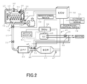
Fig. 2 is a schematic view illustrating an example of an SCR system to which the present invention is applied. -
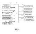
Fig. 3 is a figure illustrating an input/output configuration of a DCU. - A preferred embodiment of the present invention will be hereinafter explained with reference to appended drawings.
- First, an exhaust gas purification system of an engine will be explained with reference to
Fig. 2 . - In
Fig. 2 , anintake pipe 12 is connected to anintake manifold 11 of adiesel engine 10, and adischarge pipe 14 is connected to anexhaust manifold 13. Theintake pipe 12 is provided with anair flow sensor 15 for measuring the amount of intake, and with theair flow sensor 15, the degree of opening of theintake throttle valve 16 is controlled, whereby the amount of intake is adjusted. - The
exhaust manifold 13 and theintake manifold 11 are connected with an EGR (Exhaust Gas Recirculation)pipe 17 for returning a portion of the exhaust gas back to the intake system of theengine 10 to reduce NOx, and theEGR cooler 18 and theEGR valve 19 are connected to the EGRpipe 17. - In the
discharge pipe 14, anexhaust brake valve 20 and anexhaust throttle valve 21 are connected. Adiesel particulate filter 22 and anSCR catalyst 23 are provided downstream thereof. - The
ECU 30 receives detection values of various kinds of detection means, that is, the detection value of arotation sensor 31 for detecting the RPM of the engine, the detection value of avehicle speed sensor 32, the detection value of anoutdoor temperature sensor 33, and the detection value of anatmospheric pressure sensor 34. - The
ECU 30 controls the amount of injection of fuel at thefuel injector 35 in accordance with the degree of opening of acceleration while the vehicle is driving, and controls theintake throttle valve 16, theexhaust brake valve 20, and theexhaust throttle valve 21 as necessary and controls the amount of EGR by opening/closing theEGR valve 19. - Subsequently, an
SCR system 40 made of anSCR catalyst 23 for processing NOx in the exhaust gas from theengine 10 will be explained. - This
SCR system 40 includes anSCR catalyst 23 provided in thedischarge pipe 14 of theengine 10, adosing valve 41 for injecting urea water at the upstream side (the upstream side of the exhaust gas) of theSCR catalyst 23, aurea tank 42 for storing the urea water, an SM pump for sucking the urea water in theurea tank 42 and providing the urea water to thedosing valve 41, and asupply module 43 having a reverting valve for reverting the surplus urea water back to theurea tank 42, and a dosing control unit (DCU; Dosing Control Unit) 44 for controlling thedosing valve 41, thesupply module 43, and the like. - The
ECU 30 outputs an engine parameter to thedosing control unit 44 in accordance with operation state of theengine 10, and accordingly, thedosing control unit 44 controls thesupply module 43 and thedosing valve 41 on the basis of the detection value of each sensor explained below. - An
exhaust temperature sensor 45 for measuring the temperature of the exhaust gas at the entrance of the SCR catalyst 23 (SCR entrance temperature) is provided in thedischarge pipe 14 at the upstream side of thedosing valve 41. An upstreamside NOx sensor 46 for detecting the NOx concentration at the upstream side of theSCR catalyst 23 is provided at the upstream side of theSCR catalyst 23. A downstreamside NOx sensor 47 for detecting the NOx concentration at the downstream side of theSCR catalyst 23 is provided at the downstream side of theSCR catalyst 23. - An
SCR sensor 48 for measuring the water level, the quality, the temperature, and the like of the urea water is provided in theurea tank 42. - A
cooling line 49 for circulating the cooling water for cooling theengine 10 is connected to the ureatank 42 and thesupply module 43. Thecooling line 49 passes through theurea tank 42, and heat exchange is performed between the cooling water flowing through thecooling line 49 and the urea water in theurea tank 42. - The
cooling line 49 is provided with a tank heater valve (coolant valve) 50 for switching whether the cooling water is provided to theurea tank 42 or not. Thecooling line 49 is also connected to thedosing valve 41, but regardless of open/close of thetank heater valve 50, thedosing valve 41 is configured to provide the cooling water. - It should be noted that the
cooling line 49 is provided to also cool thesupply module 43, although simplified and not shown inFig. 2 . - Subsequently, input/output configuration of the dosing control unit (DCU) 44 for controlling the
dosing valve 41 and thesupply module 43 will be explained with reference toFig. 3 . - As shown in
Fig. 3 , theDCU 44 receives the detection values of the upstreamside NOx sensor 46, the downstreamside NOx sensor 47, the SCR sensor 48 (a water level sensor, a temperature sensor, a quality sensor), theexhaust temperature sensor 45, and anSM temperature sensor 51 and a ureawater pressure sensor 52 of thesupply module 43, and also receives signals of an outdoor air temperature, an atmospheric pressure, an engine parameter (the engine RPM, the amount of injection of fuel commanded, the engine water temperature, and the like) from theECU 30. - The DCU 44 controls the
tank heater valve 50, anSM pump 53 and a revertingvalve 54 of thesupply module 43, thedosing valve 41, an upstream side NOx sensor heater 46H, and the downstream sideNOx sensor heater 47H. - The basic control of this DCU 44 will be explained.
- First, the DCU 44 performs pre-heating control of the upstream
side NOx sensor 46 and the downstreamside NOx sensor 47 when the engine is started. More specifically, the upstream side NOx sensor heater 46H and the downstream sideNOx sensor heater 47H performs preheats the upstreamside NOx sensor 46 and the downstreamside NOx sensor 47, and thereafter, after the effect of the condensed water such as moisture content is eliminated, the upstreamside NOx sensor 46 and the downstreamside NOx sensor 47 are maintained at a high temperature to detect the NOx. - Subsequently, after the pre-heating control, the
DCU 44 determines the basic urea water amount on the basis of the value of the upstreamside NOx sensor 46, corrects the basic urea water amount on the basis of, such as the engine parameter signal and the detection value of the downstreamside NOx sensor 47, and determines the urea water amount which is injected from thedosing valve 41 to theSCR catalyst 23. - In the present invention, in the period in which pre-heating control is performed, the upstream
side NOx sensor 46 and the downstreamside NOx sensor 47 do not detect NOx; therefore, theDCU 44 controls the amount of urea spray in accordance with the engine parameter serving as the engine operation condition given by theECU 30, the outdoor air temperature, the atmospheric pressure, and the engine water temperature. - This urea spray SCR control system will be explained with reference to
Fig. 1 . -
Fig. 1 illustrates an example of configuration of a NOx model map stored in theDCU 44 explained with reference toFig. 3 . -
Fig. 1 is an example of a NOx model map when an EGR control is performed. InFig. 1 , three NOx model maps 60-1, 60-2, 60-3 according to the atmospheric pressure condition are provided, and further, an engine watertemperature correction map 61 is provided. In these three NOx model maps 60-1, 60-2, 60-3, the first NOx model map 60-1 is a base map under an atmospheric pressure condition (1) at the ground, and the second NOx model map 60-2 is acorrection map 1 under an atmospheric pressure condition (2) corresponding to, for example, an altitude of 1000 m, and a third NOx model map 60-3 is acorrection map 2 under an atmospheric pressure condition (3) corresponding to, for example, an altitude of 2000 m. - First, the first NOx model map 60-1 stores multiple outdoor air temperature-dependent NOx maps 62a1, 62b1, 62c1, 62d1 according to the outdoor air temperature (configured in a range of, for example, 40°C to +40°C), and an outdoor temperature map selection factor 63-1 receiving the outdoor air temperature and selecting two outdoor air temperature-dependent NOx maps from these outdoor air temperature-dependent NOx maps 62a1, 62b1, 62c1, 62d1 in accordance with the outdoor air temperature.
- These outdoor air temperature-dependent NOx map 62a1, 62b1, 62c1, 62d1 store the amount of NOx determined for each of the amount of injection of fuel commanded and the engine torque when the engine is operated at the outdoor air temperature configured. From the detected outdoor air temperature, the outdoor temperature map selection factor 63-1 selects, from among the outdoor air temperature-dependent NOx maps 62a1, 62b1, 62c1, 62d1, an outdoor air temperature-dependent NOx map (e.g., 62b1) that is configured higher than the detected outdoor air temperature and an outdoor air temperature-dependent NOx map 62c1 that is configured lower than the detected outdoor air temperature, and interpolates the NOx values determined by the outdoor air temperature-dependent NOx maps 62b1, 62c1 with the outdoor air temperature, and outputs the NOx values to an adding
device 66. - In contrast to the first NOx model map 60-1, the second, third NOx model maps 60-2, 60-3 include the atmospheric pressure conditions (2), (3) that have been configured, the outdoor air temperature-dependent NOx maps 62a2, 62a3, 62b2, 62b3, 62c2, 62c3, 62d2, 62d3 that have been configured, and
correction maps device 66. - In these three NOx model maps 60-1, 60-2, 60-3, first, with the first NOx model map 60-1, the NOx value is determined based on the engine operation state (the engine RPM and the amount of injection commanded) and the outdoor air temperature, and the NOx value is input into the adding
device 66, and in accordance with the atmospheric pressure condition (2), (3), the correction NOx value is input into the addingdevice 66 from any one of the multiplying devices 65-2, 65-3 of the second, third NOx model maps 60-2, 60-3. The NOx value of the first NOx model map 60-1 is corrected with the atmospheric pressure conditions (2), (3), and is output to the multiplyingdevice 67, and the multiplyingdevice 67 multiplies it by the correction value given based on the engine water temperature derived from the engine watertemperature correction map 61, and the NOx value is output on the basis of the atmospheric pressure, the outdoor air temperature, and the engine water temperature. - These three NOx model maps 60-1, 60-2, 60-3 are an example of configuration illustrating maps when the EGR control is performed. The engine-out NOx value when the EGR control is not performed is different from the NOx value when the EGR control is performed; therefore, three NOx model maps 60 are separately stored to the
DCU 44 in view of a case where the EGR control is not performed. - The
DCU 44 determines the amount of urea injected by thedosing valve 41 on the basis of the NOx value determined on the basis of the NOx model maps 60-1, 60-2, 60-3 and the engine watertemperature correction map 61 in accordance with the engine operation condition (the engine RPM and the amount of injection commanded). - Accordingly, even when NOx is not detected by the
NOx sensors - In the present invention, in order to solve the deviation between the NOx model map and the actual amount of NOx, the NOx model maps corresponding to the difference in the environment (the atmospheric pressure, the outdoor air temperature, the engine water temperature, and the like) are stored to the
DCU 44, and by deriving the amount of NOx in association with the difference in the environment, the deviation of the actual amount of NOx can be solved. It is natural that, when there are more maps, the accuracy of the amount of NOx increases, but making extreme number of maps is impractical; therefore, a certain number of maps are made, and the amounts of NOx therebetween is supported by the interpolation values. - As described above, with the present invention, the deviation from the actual amount of NOx can be reduced by making NOx model maps corresponding to the difference in the environment; therefore, with appropriately urea spray control, the effect on the exhaust gas performance can be eliminated, and the false diagnosis of the malfunction diagnosis can be prevented, and further, the diagnosis accuracy (threshold value) can be improved.
- In the above embodiments, for example, the three NOx model maps 60 and the engine water
temperature correction map 61 are used to determine the NOx value. Alternatively, there may be four or more NOx model maps 60 which are made by further dividing the atmospheric pressure conditions. In the above embodiments, for example, four temperature-dependent NOx maps are provided. Alternatively, four or more temperature-dependent NOx maps may be provided. Further, for example, in this explanation, one of the three NOx model maps 60 is adopted as a base map, and the other of the three NOx model maps 60 are correction maps. Alternatively, they may be constituted by base maps independent under the respective atmospheric pressure condition. - For example, in this explanation, the NOx model maps 60 are stored to the
DCU 44. Alternatively, the NOx model maps 60 may be stored to theECU 30. -
- 10 engine
- 14 discharge pipe
- 23 SCR catalyst
- 41 dosing valve
- 46 upstream side NOx sensor
- 47 downstream side NOx sensor
- 60-1 to 60-3 NOx model map
Claims (4)
- A urea spray SCR control system comprising an SCR catalyst provided in a discharge pipe of an engine and a dosing valve for injecting urea water at an upstream side of the SCR catalyst, wherein the urea spray SCR control system controls injection of the urea water from the dosing valve, and
the urea spray SCR control system includes a plurality of NOx model maps corresponding to an atmospheric pressure condition, an outdoor air temperature, and an engine water temperature, and determines the amount of NOx from each NOx model map on the basis of detection values of atmospheric pressure detection means, outdoor air temperature detection means, and engine water temperature detection means, and controls the amount of injection of the urea water from the dosing valve on the basis of the amount of NOx thus determined. - The urea spray SCR control system according to claim 1, wherein each of the NOx model maps is stored to a control unit, which includes a base map including a plurality of outdoor air temperature-dependent NOx maps in which the amount of NOx is set in accordance with an engine rotation and an amount of injection commanded on the basis of an outdoor air temperature under an atmospheric pressure condition at a ground level is provided, and an outdoor air temperature map selection factor for selecting an outdoor air temperature-dependent NOx map from the outdoor air temperature-dependent NOx maps using an actual outdoor air temperature, and interpolating the NOx value using the outdoor air temperature-dependent NOx map, and a correction map for correcting the NOx value given by the base map under an atmospheric pressure condition at a height, and further includes an engine water temperature correction map for correcting, with an engine water temperature, the NOx value determined by an atmospheric pressure condition and an outdoor air temperature condition.
- The urea spray SCR control system according to claim 2, wherein the control unit stores each of NOx model maps in a case where EGR control is performed and where EGR control is not performed.
- The urea spray SCR control system according to any of claims 1 to 3 comprising a NOx sensor for measuring the amount of NOx in an exhaust gas,
wherein during pre-heating control of the NOx sensor, the amount of NOx is determined from each NOx model map on the basis of the detection values of atmospheric pressure detection means, outdoor air temperature detection means, and engine water temperature detection means, and
the amount of injection of a urea water from a dosing valve is controlled on the basis of the amount of NOx determined.
Applications Claiming Priority (2)
| Application Number | Priority Date | Filing Date | Title |
|---|---|---|---|
| JP2011212943A JP5915058B2 (en) | 2011-09-28 | 2011-09-28 | Urea injection SCR control system |
| PCT/JP2012/071321 WO2013047031A1 (en) | 2011-09-28 | 2012-08-23 | Urea spray scr control system |
Publications (3)
| Publication Number | Publication Date |
|---|---|
| EP2762694A1 true EP2762694A1 (en) | 2014-08-06 |
| EP2762694A4 EP2762694A4 (en) | 2015-06-03 |
| EP2762694B1 EP2762694B1 (en) | 2017-07-26 |
Family
ID=47995081
Family Applications (1)
| Application Number | Title | Priority Date | Filing Date |
|---|---|---|---|
| EP12835975.9A Active EP2762694B1 (en) | 2011-09-28 | 2012-08-23 | Urea spray scr control system |
Country Status (5)
| Country | Link |
|---|---|
| US (1) | US9440193B2 (en) |
| EP (1) | EP2762694B1 (en) |
| JP (1) | JP5915058B2 (en) |
| CN (1) | CN103842629B (en) |
| WO (1) | WO2013047031A1 (en) |
Cited By (3)
| Publication number | Priority date | Publication date | Assignee | Title |
|---|---|---|---|---|
| CN104612791A (en) * | 2015-01-28 | 2015-05-13 | 东风商用车有限公司 | Method and system for closed-loop control of urea solution injection quantity by SCR system |
| FR3032482A1 (en) * | 2015-02-10 | 2016-08-12 | Peugeot Citroen Automobiles Sa | PROCESS FOR DEPOLLUTING OXIDES OF NITROGEN FROM AN INTERNAL COMBUSTION ENGINE |
| EP3011151A4 (en) * | 2013-06-20 | 2017-03-29 | Airqone Building Scandinavia AB | Exhaust purification system |
Families Citing this family (17)
| Publication number | Priority date | Publication date | Assignee | Title |
|---|---|---|---|---|
| JP6049058B2 (en) * | 2012-10-09 | 2016-12-21 | 株式会社サンエー | Fluid state identification device |
| US9657627B2 (en) * | 2013-05-30 | 2017-05-23 | Toyota Jidosha Kabushiki Kaisha | Abnormality diagnosis apparatus of exhaust gas purification apparatus |
| US9181835B2 (en) * | 2013-08-13 | 2015-11-10 | Caterpillar Inc. | Supervisory model predictive selective catalytic reduction control method |
| JP6365099B2 (en) | 2014-08-08 | 2018-08-01 | いすゞ自動車株式会社 | Urea water temperature management system and urea water temperature management method |
| CN204312169U (en) * | 2014-12-16 | 2015-05-06 | 天纳克(苏州)排放系统有限公司 | Urea injection system |
| CN104632323B (en) * | 2014-12-18 | 2017-02-22 | 吉林大学 | Urea SCR ammonia coverage rate feedback tracking control method |
| KR101684135B1 (en) | 2015-06-26 | 2016-12-08 | 현대자동차주식회사 | Failure diagnosis method of SCR system |
| WO2017014772A1 (en) * | 2015-07-22 | 2017-01-26 | Cummins Inc. | System and method for controlling exhaust gas temperature |
| DE102015014312A1 (en) * | 2015-11-05 | 2017-05-11 | Tropinon Enterprises Ltd. | Method for reducing the NOx emission in the exhaust system of a vehicle with an internal combustion engine |
| US9909517B2 (en) * | 2015-11-23 | 2018-03-06 | Cummins Inc. | Mult-mode controls for engines systems including SCR aftertreatment |
| GB2568439B (en) | 2016-09-30 | 2023-01-18 | Aclara Tech Llc | Enhanced meter reading schema to improve functionality in a utility's communications system |
| DE102017201867B4 (en) * | 2017-02-07 | 2023-03-02 | Robert Bosch Gmbh | Device and method for operating a heater for an exhaust gas cleaning system |
| CN110953046A (en) * | 2019-12-24 | 2020-04-03 | 无锡威孚力达催化净化器有限责任公司 | Control system for urea pump |
| JP2021179181A (en) * | 2020-05-12 | 2021-11-18 | 株式会社豊田自動織機 | Exhaust emission treatment device |
| KR20220080992A (en) * | 2020-12-08 | 2022-06-15 | 현대자동차주식회사 | Method and device for preventing fouling of cooler of exhaust gas recirculation system for engine |
| CN116971863B (en) * | 2023-07-19 | 2026-02-24 | 潍柴动力股份有限公司 | Control method and device for urea injection quantity, readable storage medium and electronic equipment |
| CN117189320B (en) * | 2023-10-31 | 2024-03-19 | 潍柴动力股份有限公司 | Urea injection control method, device, equipment and storage medium |
Family Cites Families (19)
| Publication number | Priority date | Publication date | Assignee | Title |
|---|---|---|---|---|
| JPH06299894A (en) * | 1993-04-16 | 1994-10-25 | Toyota Motor Corp | Fuel injection control device for diesel engine |
| JPH0726943A (en) * | 1993-06-24 | 1995-01-27 | Mitsubishi Heavy Ind Ltd | Control method for denitration device |
| JPH11270382A (en) * | 1998-03-23 | 1999-10-05 | Denso Corp | Air-fuel ratio control device for internal combustion engine |
| JP2000303826A (en) | 1999-04-16 | 2000-10-31 | Isuzu Motors Ltd | Exhaust gas purification equipment for diesel engines |
| JP4172576B2 (en) * | 2001-08-31 | 2008-10-29 | 本田技研工業株式会社 | Temperature control device for humidity sensor |
| JP2003232213A (en) * | 2002-02-08 | 2003-08-22 | Toyota Motor Corp | Internal combustion engine |
| JP4093919B2 (en) | 2003-06-03 | 2008-06-04 | 株式会社日立製作所 | Control device for an internal combustion engine having an exhaust gas sensor with a heater |
| JP4668852B2 (en) * | 2006-06-12 | 2011-04-13 | 三浦工業株式会社 | Denitration equipment for combustion equipment |
| GB0614445D0 (en) * | 2006-07-20 | 2006-08-30 | Ricardo Uk Ltd | Control of selective catalytic reduction |
| DE102008036885A1 (en) * | 2008-08-07 | 2010-02-11 | Daimler Ag | Method for operating an emission control system with an SCR catalytic converter |
| US8108154B2 (en) * | 2008-12-10 | 2012-01-31 | GM Global Technology Operations LLC | NOx emission estimation systems and methods |
| JP2010174657A (en) | 2009-01-27 | 2010-08-12 | Toyota Motor Corp | Heater drive control method for exhaust component sensor |
| DE102009012093A1 (en) * | 2009-03-06 | 2010-09-09 | Man Nutzfahrzeuge Ag | Method for adjusting the dosages of the reducing agent with selective catalytic reduction |
| WO2011118095A1 (en) * | 2010-03-25 | 2011-09-29 | Udトラックス株式会社 | Engine exhaust purification device and engine exaust purification method |
| JP5533235B2 (en) * | 2010-05-17 | 2014-06-25 | いすゞ自動車株式会社 | NOx sensor diagnostic device and SCR system |
| US8762026B2 (en) * | 2010-08-24 | 2014-06-24 | GM Global Technology Operations LLC | System and method for determining engine exhaust composition |
| US8745969B2 (en) * | 2010-09-08 | 2014-06-10 | GM Global Technology Operations LLC | Methods for engine exhaust NOx control using no oxidation in the engine |
| US8881508B2 (en) * | 2011-10-31 | 2014-11-11 | Commins Inc. | SCR control system utilizing a differential NH3 and NOx measurement using an exhaust gas sensor coupled with a micro SCR catalyst |
| US20130152545A1 (en) | 2011-12-14 | 2013-06-20 | Caterpillar Inc. | Diesel eission fluid quality detection system and method |
-
2011
- 2011-09-28 JP JP2011212943A patent/JP5915058B2/en not_active Expired - Fee Related
-
2012
- 2012-08-23 CN CN201280046803.XA patent/CN103842629B/en active Active
- 2012-08-23 WO PCT/JP2012/071321 patent/WO2013047031A1/en not_active Ceased
- 2012-08-23 US US14/345,734 patent/US9440193B2/en active Active
- 2012-08-23 EP EP12835975.9A patent/EP2762694B1/en active Active
Cited By (4)
| Publication number | Priority date | Publication date | Assignee | Title |
|---|---|---|---|---|
| EP3011151A4 (en) * | 2013-06-20 | 2017-03-29 | Airqone Building Scandinavia AB | Exhaust purification system |
| CN104612791A (en) * | 2015-01-28 | 2015-05-13 | 东风商用车有限公司 | Method and system for closed-loop control of urea solution injection quantity by SCR system |
| FR3032482A1 (en) * | 2015-02-10 | 2016-08-12 | Peugeot Citroen Automobiles Sa | PROCESS FOR DEPOLLUTING OXIDES OF NITROGEN FROM AN INTERNAL COMBUSTION ENGINE |
| EP3056703A1 (en) * | 2015-02-10 | 2016-08-17 | Peugeot Citroën Automobiles SA | Method for reducing nitrogen oxides emitted from an internal combustion engine |
Also Published As
| Publication number | Publication date |
|---|---|
| JP2013072391A (en) | 2013-04-22 |
| CN103842629B (en) | 2016-05-18 |
| JP5915058B2 (en) | 2016-05-11 |
| WO2013047031A1 (en) | 2013-04-04 |
| CN103842629A (en) | 2014-06-04 |
| US20140227137A1 (en) | 2014-08-14 |
| US9440193B2 (en) | 2016-09-13 |
| EP2762694A4 (en) | 2015-06-03 |
| EP2762694B1 (en) | 2017-07-26 |
Similar Documents
| Publication | Publication Date | Title |
|---|---|---|
| EP2762694B1 (en) | Urea spray scr control system | |
| US7971426B2 (en) | Reductant injection system diagnostics | |
| US7954312B2 (en) | Approach for detecting reductant availability and make-up | |
| US7730718B2 (en) | Control system for internal combustion engine | |
| US10100695B2 (en) | Exhaust fluid dosing control system and method | |
| US10301997B2 (en) | Method for checking a temperature sensor in an SCR exhaust gas post-treatment system | |
| US5722236A (en) | Adaptive exhaust temperature estimation and control | |
| US20040244366A1 (en) | Exhaust gas purifying system and exhaust gas purifying method | |
| US9714625B2 (en) | System and method for controlling ammonia levels in a selective catalytic reduction catalyst using a nitrogen oxide sensor | |
| US20140260190A1 (en) | Exhaust Aftertreatment Control System And Method For Maximizing Fuel Efficiency While Reducing Emissions | |
| CN101285414A (en) | Reductant injection control strategy | |
| US8551432B2 (en) | System and method for injecting ammonia into an exhaust gas stream | |
| WO2011148814A1 (en) | Selective catalytic reduction system | |
| US20120174562A1 (en) | Exhaust gas purification apparatus and exhaust gas purification method for an internal combustion engine | |
| US20160123258A1 (en) | Upstream nox estimation | |
| US20170248057A1 (en) | System and method for managing temperature of urea solution | |
| US20160103110A1 (en) | Engine nox model | |
| JP4419150B2 (en) | NOx catalyst abnormality diagnosis device and abnormality diagnosis method | |
| JP6589372B2 (en) | Exhaust purification device | |
| JP2008286070A (en) | Control device for internal combustion engine | |
| JP2014202077A (en) | Control device of exhaust emission control apparatus | |
| US20070044452A1 (en) | Control device of internal combustion engine | |
| JP2018205054A (en) | Air-fuel ratio sensor temperature control device | |
| JP2016050547A (en) | Exhaust emission control system |
Legal Events
| Date | Code | Title | Description |
|---|---|---|---|
| PUAI | Public reference made under article 153(3) epc to a published international application that has entered the european phase |
Free format text: ORIGINAL CODE: 0009012 |
|
| 17P | Request for examination filed |
Effective date: 20140328 |
|
| AK | Designated contracting states |
Kind code of ref document: A1 Designated state(s): AL AT BE BG CH CY CZ DE DK EE ES FI FR GB GR HR HU IE IS IT LI LT LU LV MC MK MT NL NO PL PT RO RS SE SI SK SM TR |
|
| DAX | Request for extension of the european patent (deleted) | ||
| RA4 | Supplementary search report drawn up and despatched (corrected) |
Effective date: 20150508 |
|
| RIC1 | Information provided on ipc code assigned before grant |
Ipc: B01D 53/94 20060101ALI20150430BHEP Ipc: F01N 3/08 20060101AFI20150430BHEP Ipc: B01D 53/90 20060101ALI20150430BHEP Ipc: F01N 3/20 20060101ALI20150430BHEP |
|
| GRAP | Despatch of communication of intention to grant a patent |
Free format text: ORIGINAL CODE: EPIDOSNIGR1 |
|
| STAA | Information on the status of an ep patent application or granted ep patent |
Free format text: STATUS: GRANT OF PATENT IS INTENDED |
|
| INTG | Intention to grant announced |
Effective date: 20170203 |
|
| GRAS | Grant fee paid |
Free format text: ORIGINAL CODE: EPIDOSNIGR3 |
|
| GRAA | (expected) grant |
Free format text: ORIGINAL CODE: 0009210 |
|
| STAA | Information on the status of an ep patent application or granted ep patent |
Free format text: STATUS: THE PATENT HAS BEEN GRANTED |
|
| AK | Designated contracting states |
Kind code of ref document: B1 Designated state(s): AL AT BE BG CH CY CZ DE DK EE ES FI FR GB GR HR HU IE IS IT LI LT LU LV MC MK MT NL NO PL PT RO RS SE SI SK SM TR |
|
| REG | Reference to a national code |
Ref country code: GB Ref legal event code: FG4D |
|
| REG | Reference to a national code |
Ref country code: CH Ref legal event code: EP |
|
| REG | Reference to a national code |
Ref country code: AT Ref legal event code: REF Ref document number: 912593 Country of ref document: AT Kind code of ref document: T Effective date: 20170815 |
|
| REG | Reference to a national code |
Ref country code: IE Ref legal event code: FG4D |
|
| REG | Reference to a national code |
Ref country code: DE Ref legal event code: R096 Ref document number: 602012035128 Country of ref document: DE |
|
| REG | Reference to a national code |
Ref country code: FR Ref legal event code: PLFP Year of fee payment: 6 |
|
| REG | Reference to a national code |
Ref country code: NL Ref legal event code: MP Effective date: 20170726 |
|
| REG | Reference to a national code |
Ref country code: LT Ref legal event code: MG4D |
|
| REG | Reference to a national code |
Ref country code: AT Ref legal event code: MK05 Ref document number: 912593 Country of ref document: AT Kind code of ref document: T Effective date: 20170726 |
|
| PG25 | Lapsed in a contracting state [announced via postgrant information from national office to epo] |
Ref country code: SE Free format text: LAPSE BECAUSE OF FAILURE TO SUBMIT A TRANSLATION OF THE DESCRIPTION OR TO PAY THE FEE WITHIN THE PRESCRIBED TIME-LIMIT Effective date: 20170726 Ref country code: FI Free format text: LAPSE BECAUSE OF FAILURE TO SUBMIT A TRANSLATION OF THE DESCRIPTION OR TO PAY THE FEE WITHIN THE PRESCRIBED TIME-LIMIT Effective date: 20170726 Ref country code: NL Free format text: LAPSE BECAUSE OF FAILURE TO SUBMIT A TRANSLATION OF THE DESCRIPTION OR TO PAY THE FEE WITHIN THE PRESCRIBED TIME-LIMIT Effective date: 20170726 Ref country code: LT Free format text: LAPSE BECAUSE OF FAILURE TO SUBMIT A TRANSLATION OF THE DESCRIPTION OR TO PAY THE FEE WITHIN THE PRESCRIBED TIME-LIMIT Effective date: 20170726 Ref country code: NO Free format text: LAPSE BECAUSE OF FAILURE TO SUBMIT A TRANSLATION OF THE DESCRIPTION OR TO PAY THE FEE WITHIN THE PRESCRIBED TIME-LIMIT Effective date: 20171026 Ref country code: HR Free format text: LAPSE BECAUSE OF FAILURE TO SUBMIT A TRANSLATION OF THE DESCRIPTION OR TO PAY THE FEE WITHIN THE PRESCRIBED TIME-LIMIT Effective date: 20170726 Ref country code: AT Free format text: LAPSE BECAUSE OF FAILURE TO SUBMIT A TRANSLATION OF THE DESCRIPTION OR TO PAY THE FEE WITHIN THE PRESCRIBED TIME-LIMIT Effective date: 20170726 |
|
| PG25 | Lapsed in a contracting state [announced via postgrant information from national office to epo] |
Ref country code: IS Free format text: LAPSE BECAUSE OF FAILURE TO SUBMIT A TRANSLATION OF THE DESCRIPTION OR TO PAY THE FEE WITHIN THE PRESCRIBED TIME-LIMIT Effective date: 20171126 Ref country code: PL Free format text: LAPSE BECAUSE OF FAILURE TO SUBMIT A TRANSLATION OF THE DESCRIPTION OR TO PAY THE FEE WITHIN THE PRESCRIBED TIME-LIMIT Effective date: 20170726 Ref country code: RS Free format text: LAPSE BECAUSE OF FAILURE TO SUBMIT A TRANSLATION OF THE DESCRIPTION OR TO PAY THE FEE WITHIN THE PRESCRIBED TIME-LIMIT Effective date: 20170726 Ref country code: LV Free format text: LAPSE BECAUSE OF FAILURE TO SUBMIT A TRANSLATION OF THE DESCRIPTION OR TO PAY THE FEE WITHIN THE PRESCRIBED TIME-LIMIT Effective date: 20170726 Ref country code: ES Free format text: LAPSE BECAUSE OF FAILURE TO SUBMIT A TRANSLATION OF THE DESCRIPTION OR TO PAY THE FEE WITHIN THE PRESCRIBED TIME-LIMIT Effective date: 20170726 Ref country code: GR Free format text: LAPSE BECAUSE OF FAILURE TO SUBMIT A TRANSLATION OF THE DESCRIPTION OR TO PAY THE FEE WITHIN THE PRESCRIBED TIME-LIMIT Effective date: 20171027 Ref country code: BG Free format text: LAPSE BECAUSE OF FAILURE TO SUBMIT A TRANSLATION OF THE DESCRIPTION OR TO PAY THE FEE WITHIN THE PRESCRIBED TIME-LIMIT Effective date: 20171026 |
|
| REG | Reference to a national code |
Ref country code: CH Ref legal event code: PL |
|
| PG25 | Lapsed in a contracting state [announced via postgrant information from national office to epo] |
Ref country code: DK Free format text: LAPSE BECAUSE OF FAILURE TO SUBMIT A TRANSLATION OF THE DESCRIPTION OR TO PAY THE FEE WITHIN THE PRESCRIBED TIME-LIMIT Effective date: 20170726 Ref country code: CZ Free format text: LAPSE BECAUSE OF FAILURE TO SUBMIT A TRANSLATION OF THE DESCRIPTION OR TO PAY THE FEE WITHIN THE PRESCRIBED TIME-LIMIT Effective date: 20170726 Ref country code: LI Free format text: LAPSE BECAUSE OF NON-PAYMENT OF DUE FEES Effective date: 20170831 Ref country code: RO Free format text: LAPSE BECAUSE OF FAILURE TO SUBMIT A TRANSLATION OF THE DESCRIPTION OR TO PAY THE FEE WITHIN THE PRESCRIBED TIME-LIMIT Effective date: 20170726 Ref country code: CH Free format text: LAPSE BECAUSE OF NON-PAYMENT OF DUE FEES Effective date: 20170831 Ref country code: MC Free format text: LAPSE BECAUSE OF FAILURE TO SUBMIT A TRANSLATION OF THE DESCRIPTION OR TO PAY THE FEE WITHIN THE PRESCRIBED TIME-LIMIT Effective date: 20170726 |
|
| REG | Reference to a national code |
Ref country code: DE Ref legal event code: R097 Ref document number: 602012035128 Country of ref document: DE |
|
| REG | Reference to a national code |
Ref country code: IE Ref legal event code: MM4A |
|
| PG25 | Lapsed in a contracting state [announced via postgrant information from national office to epo] |
Ref country code: EE Free format text: LAPSE BECAUSE OF FAILURE TO SUBMIT A TRANSLATION OF THE DESCRIPTION OR TO PAY THE FEE WITHIN THE PRESCRIBED TIME-LIMIT Effective date: 20170726 Ref country code: SM Free format text: LAPSE BECAUSE OF FAILURE TO SUBMIT A TRANSLATION OF THE DESCRIPTION OR TO PAY THE FEE WITHIN THE PRESCRIBED TIME-LIMIT Effective date: 20170726 Ref country code: IT Free format text: LAPSE BECAUSE OF FAILURE TO SUBMIT A TRANSLATION OF THE DESCRIPTION OR TO PAY THE FEE WITHIN THE PRESCRIBED TIME-LIMIT Effective date: 20170726 Ref country code: SK Free format text: LAPSE BECAUSE OF FAILURE TO SUBMIT A TRANSLATION OF THE DESCRIPTION OR TO PAY THE FEE WITHIN THE PRESCRIBED TIME-LIMIT Effective date: 20170726 |
|
| PLBE | No opposition filed within time limit |
Free format text: ORIGINAL CODE: 0009261 |
|
| STAA | Information on the status of an ep patent application or granted ep patent |
Free format text: STATUS: NO OPPOSITION FILED WITHIN TIME LIMIT |
|
| REG | Reference to a national code |
Ref country code: BE Ref legal event code: MM Effective date: 20170831 |
|
| PG25 | Lapsed in a contracting state [announced via postgrant information from national office to epo] |
Ref country code: LU Free format text: LAPSE BECAUSE OF NON-PAYMENT OF DUE FEES Effective date: 20170823 |
|
| 26N | No opposition filed |
Effective date: 20180430 |
|
| REG | Reference to a national code |
Ref country code: FR Ref legal event code: PLFP Year of fee payment: 7 |
|
| PG25 | Lapsed in a contracting state [announced via postgrant information from national office to epo] |
Ref country code: IE Free format text: LAPSE BECAUSE OF NON-PAYMENT OF DUE FEES Effective date: 20170823 |
|
| PG25 | Lapsed in a contracting state [announced via postgrant information from national office to epo] |
Ref country code: BE Free format text: LAPSE BECAUSE OF NON-PAYMENT OF DUE FEES Effective date: 20170831 Ref country code: SI Free format text: LAPSE BECAUSE OF FAILURE TO SUBMIT A TRANSLATION OF THE DESCRIPTION OR TO PAY THE FEE WITHIN THE PRESCRIBED TIME-LIMIT Effective date: 20170726 |
|
| PG25 | Lapsed in a contracting state [announced via postgrant information from national office to epo] |
Ref country code: MT Free format text: LAPSE BECAUSE OF NON-PAYMENT OF DUE FEES Effective date: 20170823 |
|
| PG25 | Lapsed in a contracting state [announced via postgrant information from national office to epo] |
Ref country code: HU Free format text: LAPSE BECAUSE OF FAILURE TO SUBMIT A TRANSLATION OF THE DESCRIPTION OR TO PAY THE FEE WITHIN THE PRESCRIBED TIME-LIMIT; INVALID AB INITIO Effective date: 20120823 |
|
| PG25 | Lapsed in a contracting state [announced via postgrant information from national office to epo] |
Ref country code: CY Free format text: LAPSE BECAUSE OF NON-PAYMENT OF DUE FEES Effective date: 20170726 |
|
| PG25 | Lapsed in a contracting state [announced via postgrant information from national office to epo] |
Ref country code: MK Free format text: LAPSE BECAUSE OF FAILURE TO SUBMIT A TRANSLATION OF THE DESCRIPTION OR TO PAY THE FEE WITHIN THE PRESCRIBED TIME-LIMIT Effective date: 20170726 |
|
| PG25 | Lapsed in a contracting state [announced via postgrant information from national office to epo] |
Ref country code: TR Free format text: LAPSE BECAUSE OF FAILURE TO SUBMIT A TRANSLATION OF THE DESCRIPTION OR TO PAY THE FEE WITHIN THE PRESCRIBED TIME-LIMIT Effective date: 20170726 |
|
| PG25 | Lapsed in a contracting state [announced via postgrant information from national office to epo] |
Ref country code: PT Free format text: LAPSE BECAUSE OF FAILURE TO SUBMIT A TRANSLATION OF THE DESCRIPTION OR TO PAY THE FEE WITHIN THE PRESCRIBED TIME-LIMIT Effective date: 20170726 |
|
| PG25 | Lapsed in a contracting state [announced via postgrant information from national office to epo] |
Ref country code: AL Free format text: LAPSE BECAUSE OF FAILURE TO SUBMIT A TRANSLATION OF THE DESCRIPTION OR TO PAY THE FEE WITHIN THE PRESCRIBED TIME-LIMIT Effective date: 20170726 |
|
| PGFP | Annual fee paid to national office [announced via postgrant information from national office to epo] |
Ref country code: FR Payment date: 20210715 Year of fee payment: 10 |
|
| PGFP | Annual fee paid to national office [announced via postgrant information from national office to epo] |
Ref country code: GB Payment date: 20210714 Year of fee payment: 10 |
|
| GBPC | Gb: european patent ceased through non-payment of renewal fee |
Effective date: 20220823 |
|
| PG25 | Lapsed in a contracting state [announced via postgrant information from national office to epo] |
Ref country code: FR Free format text: LAPSE BECAUSE OF NON-PAYMENT OF DUE FEES Effective date: 20220831 |
|
| PG25 | Lapsed in a contracting state [announced via postgrant information from national office to epo] |
Ref country code: GB Free format text: LAPSE BECAUSE OF NON-PAYMENT OF DUE FEES Effective date: 20220823 |
|
| PGFP | Annual fee paid to national office [announced via postgrant information from national office to epo] |
Ref country code: DE Payment date: 20250724 Year of fee payment: 14 |