EP2762425A1 - Device for vertically conveying stacks with a transferring role - Google Patents
Device for vertically conveying stacks with a transferring role Download PDFInfo
- Publication number
- EP2762425A1 EP2762425A1 EP14154025.2A EP14154025A EP2762425A1 EP 2762425 A1 EP2762425 A1 EP 2762425A1 EP 14154025 A EP14154025 A EP 14154025A EP 2762425 A1 EP2762425 A1 EP 2762425A1
- Authority
- EP
- European Patent Office
- Prior art keywords
- mat
- deflection
- roller
- plane
- belt
- Prior art date
- Legal status (The legal status is an assumption and is not a legal conclusion. Google has not performed a legal analysis and makes no representation as to the accuracy of the status listed.)
- Granted
Links
- 238000013016 damping Methods 0.000 claims description 48
- 238000007599 discharging Methods 0.000 claims 1
- 238000005452 bending Methods 0.000 description 16
- 239000003381 stabilizer Substances 0.000 description 6
- 230000005540 biological transmission Effects 0.000 description 5
- 230000001133 acceleration Effects 0.000 description 4
- 230000001737 promoting effect Effects 0.000 description 4
- 230000000087 stabilizing effect Effects 0.000 description 4
- 230000002411 adverse Effects 0.000 description 2
- 229910052782 aluminium Inorganic materials 0.000 description 2
- XAGFODPZIPBFFR-UHFFFAOYSA-N aluminium Chemical compound [Al] XAGFODPZIPBFFR-UHFFFAOYSA-N 0.000 description 2
- 239000000463 material Substances 0.000 description 2
- 229910052751 metal Inorganic materials 0.000 description 2
- 239000002184 metal Substances 0.000 description 2
- 238000010521 absorption reaction Methods 0.000 description 1
- 230000015572 biosynthetic process Effects 0.000 description 1
- 239000003795 chemical substances by application Substances 0.000 description 1
- 238000004891 communication Methods 0.000 description 1
- 230000001419 dependent effect Effects 0.000 description 1
- 230000000694 effects Effects 0.000 description 1
- 229920002457 flexible plastic Polymers 0.000 description 1
- 230000007257 malfunction Effects 0.000 description 1
- NJPPVKZQTLUDBO-UHFFFAOYSA-N novaluron Chemical compound C1=C(Cl)C(OC(F)(F)C(OC(F)(F)F)F)=CC=C1NC(=O)NC(=O)C1=C(F)C=CC=C1F NJPPVKZQTLUDBO-UHFFFAOYSA-N 0.000 description 1
- 238000012856 packing Methods 0.000 description 1
- 229920003023 plastic Polymers 0.000 description 1
- 230000008092 positive effect Effects 0.000 description 1
- 239000011265 semifinished product Substances 0.000 description 1
Images


Classifications
-
- B—PERFORMING OPERATIONS; TRANSPORTING
- B65—CONVEYING; PACKING; STORING; HANDLING THIN OR FILAMENTARY MATERIAL
- B65G—TRANSPORT OR STORAGE DEVICES, e.g. CONVEYORS FOR LOADING OR TIPPING, SHOP CONVEYOR SYSTEMS OR PNEUMATIC TUBE CONVEYORS
- B65G17/00—Conveyors having an endless traction element, e.g. a chain, transmitting movement to a continuous or substantially-continuous load-carrying surface or to a series of individual load-carriers; Endless-chain conveyors in which the chains form the load-carrying surface
- B65G17/12—Conveyors having an endless traction element, e.g. a chain, transmitting movement to a continuous or substantially-continuous load-carrying surface or to a series of individual load-carriers; Endless-chain conveyors in which the chains form the load-carrying surface comprising a series of individual load-carriers fixed, or normally fixed, relative to traction element
- B65G17/123—Conveyors having an endless traction element, e.g. a chain, transmitting movement to a continuous or substantially-continuous load-carrying surface or to a series of individual load-carriers; Endless-chain conveyors in which the chains form the load-carrying surface comprising a series of individual load-carriers fixed, or normally fixed, relative to traction element arranged to keep the load-carriers horizontally during at least a part of the conveyor run
Definitions
- the invention relates to a device for the height transport of stacks.
- Hoist conveyors are known in the art which convey flat lay objects stacked one above the other from a first height to a second height via a transport device.
- the known device comprises a feed plane in which the stacks are fed to a mat element.
- This mat element is usually made flexible and is moved by a transport device.
- Known transport devices have, for example, circumferential belt elements to which the mat element is attached.
- the drive is in operative connection with the belt elements to the mat element of the Feeding level in the discharge level and move back. Since the production speeds of the articles to be transported in stacks from the elevator have substantially increased in the past, the aim is to increase the performance of the elevator.
- the object of the present invention is to avoid the abovementioned disadvantages, in particular to provide a device for transporting height of stacks, which is increased in their performance for conveying the stacks, without the stack to be transported loses its basic shape.
- the device according to the invention is formed with a drive having a plurality of gear elements, which are in operative connection with the belt elements to move the mat element from the feed plane in the discharge plane and back, wherein the transmission elements are arranged such that a Form lifting zone and a transport zone, wherein the lifting zone between the feed plane and the discharge plane, wherein in the lifting zone, the mat member provides a footprint for the stack, which is substantially perpendicular to the direction of movement of the mat element, and in the transport zone, the footprint of the mat element parallel to Movement direction of the mat element is.
- the drive as a gear element has a lower deflection roller pair in the feed plane and an upper deflection roller pair in the discharge plane
- the drive has at least one transfer roller in the discharge plane, which adjoins the upper deflection roller pair in the direction of movement of the mat element, wherein the upper deflection roller pair is substantially increased in diameter than the transfer roller. Due to the significantly enlarged upper deflection roller pair, higher transport speeds can be achieved both in the transport zone and in the lifting zone. On the other hand, the enlarged diameter acts with respect to the upper deflection roller pair, so that when changing the direction of the mat element from the lifting zone into the transport zone, the forces acting on the mat element, in particular radial accelerations can be kept low.
- the upper deflection roller pair it is conceivable for the upper deflection roller pair to have a first and a second deflection roller, wherein the diameter of the deflection rollers is increased more than approximately 20% to the diameter of the transfer roller, in particular more than approximately 50% increases to the diameter of the transfer roller more preferably about more than about 100% of the diameter of the transfer roller is increased.
- the diameter of the upper pulley pair is at least greater than 250mm.
- the device comprises that the first, the second deflection roller and the transfer roller each have an axis about which the first, the second deflection roller and the transfer roller are rotatably mounted, wherein the axes of the deflection rollers lie on a common horizontal plane, wherein the Axle of the transfer roller is above the horizontal plane, so that there is a horizontal discharge plane.
- the two upper pulleys and the transfer roller are arranged to each other such that a horizontal transport of the mat element is ensured to the deflection of the transfer roller.
- the lower deflection roller pair has a first and a second deflection roller, wherein in particular the diameters of the deflection rollers of the upper and lower Umlenkrollenpackes are the same size.
- the mat member may have two side portions, with two strap members secured to each side portion such that a front and a rear strap member are secured to the first side portion and a front and rear strap members are secured to the second side portion, the strap members of each side portion being spaced apart.
- the mat member may have a rectangular shape or a square shape, with four attachment portions being provided to cause the mat member to be connected to the circulating belt members.
- each of the four strap elements is connected to only one attachment point of the mat element.
- the attachment of each two belt elements on each side region of the mat element has the advantage that the mat element can be reliably moved through the transport zone and the lifting zone, without the mat element can tilt.
- the use of four belt elements also has the advantage that high transport speeds can be achieved, at the same time reliable deflections the gear elements are feasible without the mat element loses its desired position.
- the device according to the invention can be designed such that the front and rear belt element of the first side region are of equal length and that the front and rear belt element of the second side region are of equal length.
- the invention may include that the drive has a lower deflection roller pair in the feed plane and an upper deflection roller pair in the discharge plane, the deflection roller pairs acting as transmission elements.
- the device according to the invention can be designed such that a first deflection roller of the lower pulley pair for the deflection of the front and the rear belt member of the first side region and serves a second pulley of the lower pulley pair for the deflection of the front and rear belt element of the second side area is used.
- a first deflection roller of the upper deflection roller pair is used for the deflection of the front and the rear belt element of the first side region and a second deflection roller of the upper deflection roller pair serves for the deflection of all belt elements.
- the invention may also include that the drive comprises auxiliary rollers as gear elements, on which all are deflected, wherein in particular the auxiliary rollers are arranged between the second deflection roller of the upper deflection roller pair and the first roller of the lower deflection roller pair.
- the auxiliary rollers serve for the mat element to be able to circulate through the transport device, including the belt elements, within the elevator, wherein in the lifting zone of the base area of the mat element the stacks are moved upwards from the unloading plane into the feed plane. Arrived in the discharge level carried over the movement of the mat element, a removal of the stack, which then leave the elevator of the invention.
- the transport direction of the mat element and the stack is perpendicular to the transport direction within the lifting zone.
- the mat element is deflected along one or more gear elements, wherein the mat element is located in the transport zone, in which the footprint of the mat Matt element is parallel to the direction of movement of the mat element. Since it may be necessary in the transport zone for the mat element to undergo further deflections, a corresponding number of auxiliary rollers is provided as the gear elements for this purpose.
- a first deflection roller of the lower deflection roller pair serve for the deflection of the front and the rear belt element of the first side region and serve a second deflection roller of the lower deflection roller pair for the deflection of the front and the rear belt element of the second side region.
- a first deflection roller of the upper deflection roller pair is used for the deflection of the front and the rear belt element of the first side region and a second deflection roller of the upper deflection roller pair for the deflection of the front and the rear belt element of the second side region, wherein at the same time the front and abut the rear belt member of the first side portion of the second pulley of the upper pulley pair.
- the second deflection roller of the upper deflection roller pair is adjoined by the transfer roller, so that the stack can reliably be transferred to a next processing unit.
- a measure improving the invention can provide that a damping element is arranged in the feed plane and / or in the discharge plane, in particular that the damping element is arranged on the frame of the device.
- a significant advantage of the damping element is that it acts on the mat element in such a way that possible forces and / or impulses acting on the mat element do not cause the mat element to vibrate, which triggers disregarding of the stacks to be transported.
- the one or more damping elements advantageously act directly on the mat element and eliminate possible vibrations of the mat element.
- the damping element contacts the mat element while the stacks are transported, wherein advantageously the damping element and the mat element are made of different materials.
- the damping element is formed from a sliding material.
- the embodiment of the damping element made of a plastic can also be advantageous since, in particular, low frictional forces and / or noise develop.
- the damping element can be arranged in the feed plane and / or in the discharge plane. It has been found that, especially in the feed plane, vibrations and / or impulses on the mat element, which disadvantageously change the desired stack shape of the stack to be transported, are also transmitted to the mat element in the discharge plane.
- the rotating belt elements are deflected at defined locations by the gear elements, whereby radial forces, vibrations and / or pulses act on the belt elements, which in turn adversely affect the attached to the belt elements mat element. Since changes in direction of the revolving belt elements are present in particular in the feed plane and in the discharge plane, the use of one or more damping elements at these points is particularly expedient.
- the device for transporting height of stacks may further comprise the damping element being fixed to the frame of the device.
- the damping element may rest against the mat element before the lifting zone and / or after the lifting zone.
- the contact between the damping element and the mat element favors the absorption of any vibrations and / or forces and / or pulses that arise during the deflection of the flexible mat element and / or during the deflection of the belt elements.
- the device according to the invention can have a plurality of damping elements which act on the edge region of the mat element. This means that two or more damping elements simultaneously contact the mat element on a mat element.
- the damping element can act on the standing surface on which the stack can be placed. It is conceivable that the stack is located between the acting damping elements on the base surface, with a sufficiently large distance between the damping element and the stack is present.
- the damping element is movably arranged on the frame, in particular that a drive is provided to bring the damping element to the base of the mat element to the contact.
- the relative position of the damping element with respect to the mat element is adjustable in order to achieve an optimal contact between the damping element and the mat element, which effectively reduces or eliminates vibration on the mat element.
- the device according to the invention may comprise sensor elements which detect the travel path of the damping element and / or the position of the mat element as well as the base surface. The sensor elements can be in data communication with the drive or with a corresponding control, so that the damping element can be optimally moved to the mat element.
- the device according to the invention discloses that the damping element is a rod-like strip and / or rail, which is arranged in particular rigidly and / or immovably to the mat element.
- the formation of the damping element as a rod-like bar or rail has the advantage that a relatively large contact surface can be formed on the part of the damping element, which acts directly on the base surface of the mat element.
- effective vibrations, forces or pulses can be absorbed by such a geometrically shaped damping element.
- the device according to the invention can provide that the damping element is a roller which contacts the mat element and has an axis about which the roller rotates during the movement of the mat element.
- the roller thus rolls off during the movement of the mat element on the base surface of the mat element and can effectively record vibrations, forces or impulses which can act on the mat element, without resulting in a disheveling of the mat element located on the stack.
- the rod-like bar and / or rail which can serve as a damping element
- the roller can be connected to a drive, which ensures that the damping element is arranged movable on the frame.
- the mat element is made of a plurality of rigid mat members, which are arranged adjacent to each other, that in a deflection of the direction of movement of the mat element on the pulleys each mat member to the adjacent mat member is relatively movable.
- the mat member is formed of a plurality of individual mat members which are positioned side by side, wherein upon movement in the lifting zone the mat members are horizontally aligned and form a flat footing for each individual stack. Since the mat members are material-rigid, a deflection of the mat element is excluded. In the deflection areas, the individual mat members move individually around the respective gear elements, wherein the distance to the respective adjacent mat member in the deflection region changes or can change. Outside the deflection areas, the individual mat members to each other on a fixed distance. Thus, higher transport speeds in the transport zone and in the lifting zone are conceivable, so that a disembarking of the stack can be prevented.
- the mat element remains in the horizontal position without the risk of individual elements of the stack shifting or even falling down.
- a planar footprint for the individual stack which can no longer wavy or spherical form during the movement, which is conceivable in the prior art.
- a parcel and / or palletizing quality which increases significantly after the height transport or following the device according to the invention, can be increased.
- the device according to the invention in a palletizing the merging of the individual stacks on a pallet, which in turn is packaged as a unit.
- Another advantage with the use of mat members spaced apart from one another is that during movement of the mat member, it is less prone to vibrate, which may arise during transport of the stacks, for example.
- the mat members may be arranged in the mat element such that in the lifting zone, the mat members are at a distance from one another.
- An advantage of this embodiment is that during movement of the mat member, the clearance helps to create almost no noise between the mat members.
- the distance between the mat members also ensures that during the deflection of the direction of movement of the mat member each mat member can move accordingly to follow the direction of movement of the mat member.
- the distance is between 0.3 mm ⁇ distance ⁇ 5 mm, in particular between 1 mm ⁇ distance ⁇ 3 mm.
- the distance between two mat members is about 2mm.
- the distance depends inter alia on how strongly the transmission elements used initiate a change of direction in the elevator according to the invention.
- the distance between the mat members also depends on the object to be transported in the form of stacks. In this case, the distance should not be too large, which could also adversely affect the quality of the stack stand on the floor space.
- the mat element may be formed of metal, in particular made of aluminum.
- a low-weight mat element can be provided which stimulates the entire height conveyor including all mat elements less to vibrations.
- the device according to the invention can be designed such that the mat member has a hollow profile, wherein in particular starting from the standing surface of a mat member to the adjacent mat member each have a side wall adjoins, wherein the side walls are arranged substantially parallel to each other.
- the hollow profile contributes among other things to the fact that a low total weight of the mat element is achieved.
- the hollow profile contributes to the fact that each mat member has a sufficiently high rigidity, which has a positive effect on the horizontal transport of the stack, in particular in the lifting zone.
- the mat member is a bent part, in particular a stamped and bent part.
- each individual mat member can be produced inexpensively.
- the side wall can be aligned substantially perpendicular to the base of the mat member.
- the mat member is formed as a U-profile.
- the mat member has a rounding.
- An advantage of the rounding is that in the supply of the stacks and / or in the discharge of the stack no malfunction occur, that is, for example, individual stacks can not get stuck between the individual mat members, or can bump against the mat members, which the desired movement of the stack is disturbed.
- the distance between two adjacent mat members in the region of the rounding can increase during the deflection.
- Each individual mat member may be individually moved and / or pivoted relative to the adjacent member.
- the invention may further provide that the mat element has at least one stabilizing agent which favors a horizontal extension of the standing surface in the lifting zone, in particular that the side region of the mat member has the stabilizing agent.
- the stabilizing agent maintains the horizontal effect of the mat element in the lifting zone, without the risk that a deflection of the mat element arises, which can be caused for example by the weight of the mat element and / or by the stack to be transported.
- the mat element has means for promoting the bending ability of the mat element, wherein in particular the means is arranged on the side facing away from the standing surface of the mat element and / or that the side region of the mat member has the means for promoting the bending ability of the mat element.
- the means for promoting the bending capability of the mat element is located on the side region, it may be advantageous for this means, also referred to below as bending means, to be located on the side of the mat element facing away from the standing surface.
- This bending means can be made of a flexible plastic.
- this bending means is attached to the mat members.
- the bending means and the mat members forms a common unit.
- the means for promoting the bending ability of the mat element has a rib structure, wherein the rib structure has projection-like ribs, which are aligned transversely to the direction of movement of the mat element. This means that the rib structure in the deflection of the elevator promotes a reliable functioning deflection of the mat element and the individual mat members.
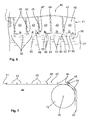
- FIG. 1 is a device for height transport, which is also referred to as elevator, represented by stacks 1.
- a stack 1 is composed of a plurality of stacked stack elements.
- the stacking elements can be, for example, flat-lying sacks, semi-finished sacks or hose sections, which have been produced in front of the height conveyor and are to be brought from a production level to a defined height level with the aid of the height conveyor. If the stack 1 leave the elevator, for example, a palletizing of the stack 1 takes place in a palletizer, which is not explicitly shown.
- the device has a transport device 20, which has a plurality of circumferential belt elements 21, 22, 23, 24, on which at least one flexible mat element 40 is arranged.
- a plurality of mat elements 40 are provided, which are moved via the transport device 20 in a lifting zone 4 and in a transport zone 5.
- the elevator has a feed plane 2 for feeding a plurality of stacks 1 to the respective mat element 40, which is shown by way of example by means of an arrow illustration.
- the transport device 20 is driven by a drive 10, the drive 10 having a plurality of gear elements 11, 12, 13, 14, 15, 16, 17, which are in operative connection with the belt elements 21, 22, 23, 24 to the Mat elements 40 from the feed level 2 in a discharge plane 3 and back to move.
- each stack 1 is removed from the respective mat element 40 and thus each stack 1 leaves the height conveyor.
- a roller system 6 is shown, which conveys each stack 1 to the next processing step, for example, for a palletization on.
- the gear elements 11-16 are arranged such that the lifting zone 4 lies between the feed plane 2 and the discharge plane 3.
- the mat element 40 offers a standing surface 48 for each stack 1.
- the standing surface 48 is aligned substantially perpendicular to the direction of movement of the mat element 40 during transport in the lifting zone 4.
- the standing surface 48 of the mat element 40 is aligned parallel to the direction of movement of the mat element 40.
- Each mat member 40 has two side portions 41, 42 which are also schematically shown in FIG FIG. 5 are shown.
- FIG. 5 the direction of movement of the mat element 40 in the lifting zone 4, in which the mat element 40 moves from the feed plane 2 upwards in the direction of the discharge plane 3 (see the arrow pointing upwards).
- the mat member 40 translates to the right, which in FIG. 5 is shown schematically by the arrow pointing to the right. The same applies if the mat element 40 has reached the discharge plane 3.
- each side portion 41, 42 two belt elements 21 - 24 are attached in each case. That means that according to FIG. 5 on the first side portion 41, a front belt member 21 and a rear belt member 22 and on the second side portion 42, a front belt member 23 and a rear belt member 24 are fixed.
- the belt elements 21-24 of each side region 41, 42 are each spaced from one another.
- the drive 10 according to FIG. 1 has a lower deflection roller pair 13, 14 in the feed plane 2 and an upper deflection roller pair 11, 12 in the discharge plane 3, wherein the Umlenkrollenforme 11, 12, 13, 14, act as transmission elements.
- FIG. 4 and FIG. 5 is simplified, the arrangement of the belt elements 21 - 24 shown within the elevator, wherein a first guide roller 13 of the lower Umlenkrollenpreses 13, 14 for the deflection of the front 21 and the rear belt member 22 of the first side portion 41 and a second guide pulley 14 of the lower pulley 13th , 14 for the deflection of the front 23 and the rear strap member 24 of the second side portion 42 is used.
- the belt elements 21-24 are aligned by the drive 10 such that the belt elements 21-24 are aligned one behind the other, the standing surface 48 of the mat element 40 being positioned parallel to the direction of movement of the mat element 40.
- FIG. 1 serves the first guide roller 11 of the upper Umlenkrollencrues 11, 12 for the deflection of the front 21 and the rear belt member 22 of the first side portion 41.
- FIG. 1 come enlarged guide rollers 11, 12, 13, 14 are used, wherein the drive 10 in the discharge plane 3 has a transfer roller 17, in the direction of movement of the mat element 10, the upper pair of rollers 11, 12th followed. It can also be provided 17 several transfer rollers.
- the upper roller pair 11, 12 has a substantially larger diameter than the transfer roller 17.
- FIG. 1 serves the first guide roller 11 of the upper roller pair 11, 12 for the deflection of the front 21 and rear belt member 22 of the first side portion 41.
- the second guide roller 12 of the upper pair of rollers 11, 12 serves to deflect the front 23 and the rear belt member 24, wherein at the same time the front 21 and the rear belt member 22 of the first side portion 41 on the second guide roller 12 of the upper roller pair 11, 12 abuts. All belt elements 21 - 24 are deflected by the transfer roller 17.
- the larger deflection rollers 11-14 bring about higher transport speeds, wherein the horizontal accelerations in the deflection points can be substantially reduced.
- the transfer roller 17, which is substantially reduced in diameter, allows a clean transfer of the stack 1, which is particularly important in the smallest sizes in the stack elements.
- a drive motor is integrated in the drive 10, which drives at least one of the many transmission elements directly.
- the drive motor may be advantageous for the drive motor to drive the gear element 12, in particular the second deflection roller 12, whereby all the belt elements 21-24 can be set in a circulating movement, so that the mat elements 40 fastened to the belt elements 21-24 are moved along.
- the device according to the invention for the height transport of stacks 1 on mat member 40 a damping element 60, wherein the damping element 60 may be arranged in the feed plane 2 and / or in the discharge plane 3.
- the damping element 60 is attached to the frame 80 of the elevator.
- a significant advantage of the damping element 60 is that it acts on the mat element 40 in such a way that possible forces and / or pulses and / or vibrations acting on the mat element 40 do not cause the mat element 40 to move in such a way that the stack to be transported is shifts or shams out.
- FIG. 1 is the damping element 60 in front of the lifting zone 4 and after the lifting zone 4 on the mat member 40th
- the damping member 60 may be a roller that contacts the mat member 40 on the pedestal 48, the roller having an axis 61 about which the roller 60 rotates during movement of the mat member 40.
- the damping element 60 according to FIG. 3 is a rod-like bar that rests rigidly on the mat member 40.
- the damping element 60 acts on the edge area 49 on the base 48.
- the damping element 60 can be movably arranged on the frame 80, wherein a drive 68 may be provided to bring the damping element 60 to the standing surface 48 of the mat member 40 until contact.
- the drive 10 has auxiliary rollers 15, 16 as gear elements on which all belt elements 21 - 24 are deflected, the auxiliary rollers 15, 16 between the second deflection roller 12 of the upper deflection roller pair 11, 12 and the first deflection roller 13 of the lower roller pair 13, 14 are arranged.
- FIG. 1 is located behind the second guide roller 12 of the upper guide roller pair 11, 12 nor the transfer roller 17 to which the auxiliary rollers 15, 16 connect.
- the first 11 and the second guide roller 12 of the upper roller pair 11, 12 and the subsequent transfer roller 17 each have an axis 18, 19 around which the first 11, the second guide roller 12 and the transfer roller 17 are rotatably mounted.
- the axes 18 of the guide rollers 11, 12 lie together on a horizontal plane, wherein the axis 19 of the transfer roller 17 is above the just mentioned horizontal plane, so that there is a horizontal discharge plane.
- the mat member 40 In order to reduce the risk of dislocation during transport within the elevator, or to achieve higher transport speeds, it is conceivable to carry out the mat member 40 with a plurality of rigid mat members 43, which in FIG. 6 and FIG. 7 is shown.
- the mat members 43 are arranged adjacent to each other such that during the deflection of the direction of movement of the mat member 40 each Mat member 43 to the adjacent mat member 43 is relatively movable.
- the mat members 43 are formed of metal, in the present embodiment of aluminum.
- Each mat member 43 has a hollow profile, wherein starting from the standing surface 48 of each mat member 43 to the adjacent mat member 43 each have a side wall 44 connects.
- the side walls 44 are arranged substantially parallel to each other. In addition, each side wall 44 is aligned substantially perpendicular to the base 48 of the mat member 43.
- the mat member 43 is formed as a U-profile, wherein between the side wall 44 and the base 48, the mat member 43 has a rounding 45.
- FIG. 7 It is shown that during the deflection in the region of the second deflection roller 12, the distance between two adjacent mat members 43 in the region of the rounding 45 increases.
- each mat element 40 has two edge regions 49, which are aligned parallel to one another in relation to the direction of movement of the mat element 40, wherein the belt elements 21-24 are fastened to the edge regions 49, as will be discussed below.
- the attachment points are located simultaneously in the region of the side regions 41, 42 of the mat element 40.
- the mat element 40 has at each of its two edge regions 49 a stabilizing means 50, which favors a horizontal extension of the standing surface 48 in the lifting zone 4.
- a stabilizing means 50 within the hollow profile of the mat member 43 and is thus adapted to the shape of the hollow profile.
- One of the two side walls 44 of the respective mat member 43 has a recess 47, through which the stabilizing means 50 extends at least partially and abuts the adjacent mat member 43 on the side wall 44.
- each mat member 40 on a bending means 51 whereby the bending ability of the mat member 40 is favored.
- the stabilizing means 50 and the bending means 51 are provided at the edge region 49 of the mat member 40.
- the bending means 51 has according to FIG.
- each mat member 53 has two adjacently arranged fastening means 46. At the same time, the stiffness of the mat element 40 can be adjusted via the fastening means 46.
- the rib structure 52 of the bending means 51 favors the bending ability of the mat element 40.
- the edge region 49 of the mat element 40 is fastened via a fastening element 56 with all the belt elements 21 to 24.
- the belt element 21 is fastened to the edge region 49 of the mat element 40 via the fastening element 56.
- the fastener 56 connects the stabilizer 50 to the associated belt member 21.
- the bearing member 55 is recessed within the clearance 54 of the rib structure 52 so that no collision with other objects within the elevator can occur.
- damping elements 60 it is conceivable in addition to the in FIG. 2 and FIG. 3 insert shown damping elements 60.
Landscapes
- Engineering & Computer Science (AREA)
- Mechanical Engineering (AREA)
- Delivering By Means Of Belts And Rollers (AREA)
Abstract
Description
Die Erfindung betrifft eine Vorrichtung zum Höhentransport von Stapeln.The invention relates to a device for the height transport of stacks.
Höhenförderer sind aus dem Stand der Technik bekannt, die flachliegende Gegenstände, die übereinander gestapelt sind, von einer ersten Höhe in eine zweite Höhe über eine Transportvorrichtung befördern. Hierbei umfasst die bekannte Vorrichtung eine Zuführebene, in der die Stapel einem Mattenelement zugeführt werden. Dieses Mattenelement ist in der Regel flexibel ausgeführt und wird über eine Transportvorrichtung bewegt. Bekannte Transportvorrichtungen weisen beispielsweise umlaufende Riemenelemente auf, an denen das Mattenelement befestigt ist. Zudem ist aus dem Stand der Technik bekannt, die Riemenelemente über einen Antrieb zu bewegen. Hierbei steht der Antrieb mit den Riemenelementen in Wirkverbindung, um das Mattenelement von der Zuführebene in die Abführebene und zurück zu bewegen. Da die Herstellungsgeschwindigkeiten bei den Gegenständen, die in Stapeln vom Höhenförderer zu transportieren sind, in der Vergangenheit wesentlich sich erhöht haben, ist das Bestreben eine Leistungssteigerung beim Höhenförderer zu bewirken. Das bedeutet, dass die Geschwindigkeit des Transports von Stapeln in der Hubzone des Höhenförderers zu steigern ist. Nachteiligerweise hat sich gezeigt, dass bei höheren Transportgeschwindigkeiten die Stapel, die sich auf dem Mattenelement befinden, zum Ausschuppen neigen, das bedeutet, dass einige Elemente, Gegenstände des Stapels sich verschieben. Folglich weist der Stapel in der Abführebene nicht mehr seine Geometrie auf, die er in der Zuführebene hatte. Falls die zu transportierenden Stapel nach dem Höhenförderer noch zu palettieren sind und/oder zu verpacken sind, ergeben sich aufgrund der veränderten Stapelform weitere Probleme. Da einige Elemente des Stapels sich nicht mehr in der gewünschten Position befinden, kann somit die anschließende Palettierqualität und/oder Packqualität nach dem Höhenförderer leiden.Hoist conveyors are known in the art which convey flat lay objects stacked one above the other from a first height to a second height via a transport device. Here, the known device comprises a feed plane in which the stacks are fed to a mat element. This mat element is usually made flexible and is moved by a transport device. Known transport devices have, for example, circumferential belt elements to which the mat element is attached. In addition, it is known from the prior art to move the belt elements via a drive. Here, the drive is in operative connection with the belt elements to the mat element of the Feeding level in the discharge level and move back. Since the production speeds of the articles to be transported in stacks from the elevator have substantially increased in the past, the aim is to increase the performance of the elevator. This means that the speed of transport of stacks in the lifting zone of the elevator has to be increased. Unfortunately, it has been found that at higher transport speeds, the stacks that are on the mat element tend to dislodge, which means that some items move items of the stack. Consequently, the stack no longer has its geometry in the discharge plane that it had in the feed plane. If the stacks to be transported are still to be palletized after the elevator, and / or are to be packed, further problems arise due to the changed stack shape. Since some elements of the stack are no longer in the desired position, thus the subsequent palletizing quality and / or packing quality may suffer after the elevator.
Die Aufgabe der vorliegenden Erfindung ist es die oben genannten Nachteile zu vermeiden, insbesondere eine Vorrichtung zum Höhentransport von Stapeln bereitzustellen, die in ihrer Leistung zur Beförderung der Stapel erhöht ist, ohne dass der zu transportierende Stapel seine Grundform verliert.The object of the present invention is to avoid the abovementioned disadvantages, in particular to provide a device for transporting height of stacks, which is increased in their performance for conveying the stacks, without the stack to be transported loses its basic shape.
Die Aufgabe der vorliegenden Erfindung wird durch sämtliche Merkmale des Patentanspruches 1 gelöst. In den abhängigen Patentansprüchen sind mögliche Ausführungsformen beschrieben.The object of the present invention is achieved by all features of
Erfindungsgemäß umfasst die Vorrichtung zum Höhentransport von Stapeln, insbesondere Säcken, Halbzeugen, Schlauchabschnitten oder flachliegenden Säcken eine Transportvorrichtung, die mehrere, umlaufende Riemenelemente aufweist, an denen zumindest ein flexibles Mattenelement angeordnet ist, eine Zuführebene, um Stapel dem Mattenelement zuzuführen, eine Abführebene, um Stapel von dem Mattenelement abzuführen. Zudem ist die erfindungsgemäße Vorrichtung mit einem Antrieb ausgebildet, der eine Vielzahl an Getriebeelementen aufweist, die in Wirkverbindung mit den Riemenelementen stehen, um das Mattenelement von der Zuführebene in die Abführebene und zurück zu bewegen, wobei die Getriebeelemente derart angeordnet sind, dass sich eine Hubzone und eine Transportzone bilden, wobei die Hubzone zwischen der Zuführebene und der Abführebene liegt, wobei in der Hubzone das Mattenelement eine Standfläche für den Stapel bietet, die im wesentlichen senkrecht zur Bewegungsrichtung des Mattenelementes ist, und in der Transportzone die Standfläche des Mattenelementes parallel zur Bewegungsrichtung des Mattenelementes ist. Ein wesentlicher Kern der Erfindung ist, dass der Antrieb als Getriebeelement ein unteres Umlenkrollenpaar in der Zuführebene und ein oberes Umlenkrollenpaar in der Abführebene aufweist, der Antrieb in der Abführebene mindestens eine Übergaberolle aufweist, die sich in Bewegungsrichtung des Mattenelementes dem oberen Umlenkrollenpaar anschließt, wobei das obere Umlenkrollenpaar in seinem Durchmesser wesentlich vergrößert ist als die Übergaberolle. Aufgrund des wesentlich vergrößerten oberen Umlenkrollenpaars, können zum einen höhere Transportgeschwindigkeiten sowohl in der Transportzone als auch in der Hubzone erreicht werden. Zum anderen wirkt der vergrößerte Durchmesser bezüglich des oberen Umlenkrollenpaares, so dass beim Richtungswechsel des Mattenelementes von der Hubzone in die Transportzone, die auf das Mattenelement wirkenden Kräfte, insbesondere radiale Beschleunigungen gering gehalten werden können. Somit kann wirkungsvoll vermieden werden, dass der auf dem Mattenelement liegende Stapel verreißt, das bedeutet sich verschiebt und somit die ursprüngliche Stapelform verlässt, die er in der Zuführebene hatte. Das soeben genannte Verschieben einzelner Stapelelemente wird im Folgenden auch als "Ausschuppung" bezeichnet. Ebenfalls ist es denkbar, dass die Zuführebene die Abführebene ist und/oder umgekehrt.According to the invention, the device for transporting the height of stacks, in particular sacks, semi-finished products, hose sections or flat bags comprises a transport device having a plurality of circumferential belt elements, on which at least one flexible mat element is arranged, a feed plane to supply stacks to the mat element, a discharge plane Remove stacks from the mat element. In addition, the device according to the invention is formed with a drive having a plurality of gear elements, which are in operative connection with the belt elements to move the mat element from the feed plane in the discharge plane and back, wherein the transmission elements are arranged such that a Form lifting zone and a transport zone, wherein the lifting zone between the feed plane and the discharge plane, wherein in the lifting zone, the mat member provides a footprint for the stack, which is substantially perpendicular to the direction of movement of the mat element, and in the transport zone, the footprint of the mat element parallel to Movement direction of the mat element is. An essential core of the invention is that the drive as a gear element has a lower deflection roller pair in the feed plane and an upper deflection roller pair in the discharge plane, the drive has at least one transfer roller in the discharge plane, which adjoins the upper deflection roller pair in the direction of movement of the mat element, wherein the upper deflection roller pair is substantially increased in diameter than the transfer roller. Due to the significantly enlarged upper deflection roller pair, higher transport speeds can be achieved both in the transport zone and in the lifting zone. On the other hand, the enlarged diameter acts with respect to the upper deflection roller pair, so that when changing the direction of the mat element from the lifting zone into the transport zone, the forces acting on the mat element, in particular radial accelerations can be kept low. Thus, it can be effectively avoided that the stack lying on the mat element tears, that is, shifts and thus leaves the original stack shape, which he had in the feed level. The just mentioned shifting of individual stack elements is also referred to below as "disembarkation". It is also conceivable that the feed level is the discharge level and / or vice versa.
In einer möglichen Ausführungsform der Erfindung ist es denkbar, dass das obere Umlenkrollenpaar eine erste und eine zweite Umlenkrolle aufweist, wobei der Durchmesser der Umlenkrollen mehr als ungefähr 20% zum Durchmesser der Übergaberolle vergrößert ist, insbesondere mehr als ungefähr 50% zum Durchmesser der Übergaberolle vergrößert ist, besonders bevorzugt mehr als ungefähr 100% zum Durchmesser der Übergaberolle vergrößert ist. Vorteilhafterweise ist der Durchmesser des oberen Umlenkrollenpaares mindestens größer als 250mm. Somit können höhere Transportgeschwindigkeiten bei einer reduzierten horizontalen Beschleunigung im Umlenkbereich erzielt werden, der direkt sich nach der Hubzone anschließt. Somit lässt sich ein häufiges im Stand der Technik auftretendes Ausschuppen oder Verziehen der Pakete wirksam vermeiden und die Folge ist, dass bei der weiteren Verarbeitung der Stapel keine Probleme entstehen, so dass eine mögliche folgende Palettierung der Stapel in einem nächsten Verarbeitungsschritt in ihrer Qualität nicht gestört ist.In one possible embodiment of the invention, it is conceivable for the upper deflection roller pair to have a first and a second deflection roller, wherein the diameter of the deflection rollers is increased more than approximately 20% to the diameter of the transfer roller, in particular more than approximately 50% increases to the diameter of the transfer roller more preferably about more than about 100% of the diameter of the transfer roller is increased. Advantageously, the diameter of the upper pulley pair is at least greater than 250mm. Thus, higher transport speeds can be achieved with a reduced horizontal acceleration in the deflection, which connects directly after the lifting zone. Thus, a frequent occurring in the prior art padding or warping the packages can be effectively avoided and the result is that in the further processing of the stack no problems arise, so that a possible subsequent palletization of the stack in a next processing step is not disturbed in their quality.
Ferner umfasst die erfindungsgemäße Vorrichtung, dass die erste, die zweite Umlenkrolle sowie die Übergaberolle jeweils eine Achse aufweisen, um die die erste, die zweite Umlenkrolle sowie die Übergaberolle drehbar gelagert sind, wobei die Achsen der Umlenkrollen auf einer gemeinsamen horizontalen Ebene liegen, wobei die Achse der Übergaberolle oberhalb der horizontalen Ebene liegt, so dass sich eine waagerechte Abführebene ergibt. Vorteilhafterweise sind die beiden oberen Umlenkrollen sowie die Übergaberolle derart zueinander angeordnet, dass ein waagerechter Transport des Mattenelementes bis zum Umlenkbereich an der Übergaberolle sichergestellt ist.Furthermore, the device according to the invention comprises that the first, the second deflection roller and the transfer roller each have an axis about which the first, the second deflection roller and the transfer roller are rotatably mounted, wherein the axes of the deflection rollers lie on a common horizontal plane, wherein the Axle of the transfer roller is above the horizontal plane, so that there is a horizontal discharge plane. Advantageously, the two upper pulleys and the transfer roller are arranged to each other such that a horizontal transport of the mat element is ensured to the deflection of the transfer roller.
Erfindungsgemäß ist es denkbar, dass das untere Umlenkrollenpaar eine erste und eine zweite Umlenkrolle aufweist, wobei insbesondere die Durchmesser der Umlenkrollen des oberen und des unteren Umlenkrollenpaares gleichgroß sind. Durch diese Ausgestaltung der Erfindung wird wirksam erreicht, dass im unteren Umlenkbereich, das heißt kurz vor der Hubzone eine reduzierte Horizontalbeschleunigung auf das Mattenelement wirkt.According to the invention, it is conceivable that the lower deflection roller pair has a first and a second deflection roller, wherein in particular the diameters of the deflection rollers of the upper and lower Umlenkrollenpaares are the same size. This refinement of the invention effectively achieves that in the lower deflecting region, that is to say shortly before the lifting zone, a reduced horizontal acceleration acts on the mat element.
Vorteilhafterweise kann das Mattenelement zwei Seitenbereiche aufweisen, wobei an jedem Seitenbereich zwei Riemenelemente befestigt sind, so dass am ersten Seitenbereich ein vorderes und ein hinteres Riemenelement und am zweiten Seitenbereich ein vorderes und ein hinteres Riemenelement befestigt sind, wobei die Riemenelemente jedes Seitenbereiches voneinander beabstandet sind. Beispielsweise kann das Mattenelement eine Rechteckförmige Gestalt oder eine quadratförmige Gestalt aufweisen, wobei vier Befestigungsbereiche vorgesehen sind, die dafür sorgen, dass das Mattenelement mit den umlaufenden Riemenelementen verbunden ist. Vorteilhafterweise ist jedes der vier Riemenelemente mit lediglich einem Befestigungspunkt des Mattenelementes verbunden. Die Befestigung von jeweils zwei Riemenelementen an jedem Seitenbereich des Mattenelementes hat den Vorteil, dass das Mattenelement zuverlässig durch die Transportzone und die Hubzone verfahren werden kann, ohne dass das Mattenelement verkippen kann. Der Einsatz von vier Riemenelementen hat zudem den Vorteil, dass hohe Transportgeschwindigkeiten erzielbar sind, wobei gleichzeitig zuverlässig Umlenkungen an den Getriebeelementen durchführbar sind, ohne dass das Mattenelement seine gewünschte Lage verliert.Advantageously, the mat member may have two side portions, with two strap members secured to each side portion such that a front and a rear strap member are secured to the first side portion and a front and rear strap members are secured to the second side portion, the strap members of each side portion being spaced apart. For example, the mat member may have a rectangular shape or a square shape, with four attachment portions being provided to cause the mat member to be connected to the circulating belt members. Advantageously, each of the four strap elements is connected to only one attachment point of the mat element. The attachment of each two belt elements on each side region of the mat element has the advantage that the mat element can be reliably moved through the transport zone and the lifting zone, without the mat element can tilt. The use of four belt elements also has the advantage that high transport speeds can be achieved, at the same time reliable deflections the gear elements are feasible without the mat element loses its desired position.
Des Weiteren kann die erfindungsgemäße Vorrichtung derart ausgebildet sein, dass das vordere und hintere Riemenelement des ersten Seitenbereiches gleich lang und dass das vordere und hintere Riemenelement des zweiten Seitenbereiches gleich lang ausgeführt sind. Alternativ und/oder zusätzlich kann die Erfindung mitumfassen, dass der Antrieb ein unteres Umlenkrollenpaar in der Zuführebene und ein oberes Umlenkrollenpaar in der Abführebene aufweist, wobei die Umlenkrollenpaare als Getriebeelemente wirken.Furthermore, the device according to the invention can be designed such that the front and rear belt element of the first side region are of equal length and that the front and rear belt element of the second side region are of equal length. Alternatively and / or additionally, the invention may include that the drive has a lower deflection roller pair in the feed plane and an upper deflection roller pair in the discharge plane, the deflection roller pairs acting as transmission elements.
In einer weiteren die Erfindung verbessernden Maßnahme, kann die erfindungsgemäße Vorrichtung derart ausgebildet sein, dass eine erste Umlenkrolle des unteren Umlenkrollenpaares für die Umlenkung des vorderen und des hinteren Riemenelementes des ersten Seitenbereiches dient und eine zweite Umlenkrolle des unteren Umlenkrollenpaares für die Umlenkung des vorderen und des hinteren Riemenelementes des zweiten Seitenbereiches dient. Zudem ist es denkbar, dass eine erste Umlenkrolle des oberen Umlenkrollenpaares für die Umlenkung des vorderen und des hinteren Riemenelementes des ersten Seitenbereiches dient und eine zweite Umlenkrolle des oberen Umlenkrollenpaares für die Umlenkung aller Riemenelemente dient. Ebenfalls kann die Erfindung miteinschließen, dass der Antrieb Hilfsrollen als Getriebeelemente aufweist, an denen alle umgelenkt werden, wobei insbesondere die Hilfsrollen zwischen der zweiten Umlenkrolle des oberen Umlenkrollenpaares und der ersten Rolle des unteren Umlenkrollenpaares angeordnet sind. Die Hilfsrollen dienen unter anderem dazu, dass das Mattenelement durch die Transportvorrichtung, einschließlich der Riemenelemente, innerhalb des Höhenförderers umlaufen kann, wobei in der Hubzone der Standfläche des Mattenelementes die Stapel von der Abführebene in die Zuführebene nach oben bewegt werden. In der Abführebene angekommen erfolgt über die Bewegung des Mattenelementes ein Abtransport der Stapel, die anschließend den erfindungsgemäßen Höhenförderer verlassen. An dieser Stelle des Höhenförderers ist die Transportrichtung des Mattenelementes sowie der Stapel senkrecht zur Transportrichtung innerhalb der Hubzone. Nachdem der Stapel in der Abführebene das Mattenelement verlässt, erfolgt eine Umlenkung des Mattenelementes entlang eines oder mehrerer Getriebeelemente, wobei das Mattenelement sich in der Transportzone befindet, in der die Standfläche des Mattenelementes parallel zur Bewegungsrichtung des Mattenelementes ist. Da in der Transportzone es notwendig sein kann, dass das Mattenelement weitere Umlenkungen erfährt, ist hierfür eine entsprechende Anzahl an Hilfsrollen als Getriebeelemente vorgesehen.In a further measure improving the invention, the device according to the invention can be designed such that a first deflection roller of the lower pulley pair for the deflection of the front and the rear belt member of the first side region and serves a second pulley of the lower pulley pair for the deflection of the front and rear belt element of the second side area is used. In addition, it is conceivable that a first deflection roller of the upper deflection roller pair is used for the deflection of the front and the rear belt element of the first side region and a second deflection roller of the upper deflection roller pair serves for the deflection of all belt elements. The invention may also include that the drive comprises auxiliary rollers as gear elements, on which all are deflected, wherein in particular the auxiliary rollers are arranged between the second deflection roller of the upper deflection roller pair and the first roller of the lower deflection roller pair. Among other things, the auxiliary rollers serve for the mat element to be able to circulate through the transport device, including the belt elements, within the elevator, wherein in the lifting zone of the base area of the mat element the stacks are moved upwards from the unloading plane into the feed plane. Arrived in the discharge level carried over the movement of the mat element, a removal of the stack, which then leave the elevator of the invention. At this point of the elevator, the transport direction of the mat element and the stack is perpendicular to the transport direction within the lifting zone. After the stack leaves the mat element in the discharge plane, the mat element is deflected along one or more gear elements, wherein the mat element is located in the transport zone, in which the footprint of the mat Matt element is parallel to the direction of movement of the mat element. Since it may be necessary in the transport zone for the mat element to undergo further deflections, a corresponding number of auxiliary rollers is provided as the gear elements for this purpose.
Vorteilhafterweise kann eine erste Umlenkrolle des unteren Umlenkrollenpaares für die Umlenkung des vorderen und des hinteren Riemenelementes des ersten Seitenbereiches dienen und eine zweite Umlenkrolle des unteren Umlenkrollenpaares für die Umlenkung des vorderen und des hinteren Riemenelementes des zweiten Seitenbereiches dienen. Ebenfalls kann vorgesehen sein, dass eine erste Umlenkrolle des oberen Umlenkrollenpaares für die Umlenkung des vorderen und des hinteren Riemenelementes des ersten Seitenbereiches dient und eine zweite Umlenkrolle des oberen Umlenkrollenpaares für die Umlenkung des vorderen und des hinteren Riemenelementes des zweiten Seitenbereiches dient, wobei gleichzeitig das vordere und das hintere Riemenelement des ersten Seitenbereiches an der zweiten Umlenkrolle des oberen Umlenkrollenpaares anliegen. Der zweiten Umlenkrolle des oberen Umlenkrollepaares schließt sich erfindungsgemäß die Übergaberolle an, so dass zuverlässig der Stapel einer nächsten Verarbeitungseinheit übergeben werden kann.Advantageously, a first deflection roller of the lower deflection roller pair serve for the deflection of the front and the rear belt element of the first side region and serve a second deflection roller of the lower deflection roller pair for the deflection of the front and the rear belt element of the second side region. It can also be provided that a first deflection roller of the upper deflection roller pair is used for the deflection of the front and the rear belt element of the first side region and a second deflection roller of the upper deflection roller pair for the deflection of the front and the rear belt element of the second side region, wherein at the same time the front and abut the rear belt member of the first side portion of the second pulley of the upper pulley pair. According to the invention, the second deflection roller of the upper deflection roller pair is adjoined by the transfer roller, so that the stack can reliably be transferred to a next processing unit.
Eine die Erfindung verbessernde Maßnahme kann vorsehen, dass ein Dämpfungselement in der Zuführebene und/oder in der Abführebene angeordnet ist, insbesondere dass das Dämpfungselement am Gestell der Vorrichtung angeordnet ist. Ein wesentlicher Vorteil des Dämpfungselementes ist, dass dieses derart auf das Mattenelement wirkt, dass mögliche auf das Mattenelement wirkende Kräfte und/oder Impulse nicht bewirken, dass das Mattenelement in Schwingungen gerät, die ein Ausschuppen der zu transportierenden Stapel auslösen. Das oder die Dämpfungselemente wirken vorteilhafterweise direkt auf das Mattenelement und eliminieren mögliche Schwingungen des Mattenelements. Vorteilhafterweise kontaktiert das Dämpfungselement das Mattenelement während die Stapel transportiert werden, wobei vorteilhafterweise das Dämpfungselement sowie das Mattenelement aus unterschiedlichen Werkstoffen ausgebildet sind. In einer möglichen Ausführungsform der Erfindung ist das Dämpfungselement aus einem Gleitwerkstoff ausgebildet. Die Ausführung des Dämpfungselementes aus einem Kunststoff kann ebenfalls von Vorteil sein, da insbesondere geringe Reibungskräfte und/oder Geräuschentwicklungen entstehen.A measure improving the invention can provide that a damping element is arranged in the feed plane and / or in the discharge plane, in particular that the damping element is arranged on the frame of the device. A significant advantage of the damping element is that it acts on the mat element in such a way that possible forces and / or impulses acting on the mat element do not cause the mat element to vibrate, which triggers disregarding of the stacks to be transported. The one or more damping elements advantageously act directly on the mat element and eliminate possible vibrations of the mat element. Advantageously, the damping element contacts the mat element while the stacks are transported, wherein advantageously the damping element and the mat element are made of different materials. In one possible embodiment of the invention, the damping element is formed from a sliding material. The embodiment of the damping element made of a plastic can also be advantageous since, in particular, low frictional forces and / or noise develop.
In einer die Erfindung verbessernden Maßnahme kann das Dämpfungselement in der Zuführebene und/oder in der Abführebene angeordnet sein. Es hat sich gezeigt, dass besonders in der Zuführebene das auch in der Abführebene Schwingungen und/oder Impulse auf das Mattenelement besonders häufig übertragen werden, die nachteiligerweise die gewünschte Stapelform des zu transportierenden Stapels verändern. Die umlaufenden Riemenelemente werden an definierten Orten durch die Getriebeelemente umgelenkt, wodurch radiale Kräfte, Schwingungen und/oder Impulse auf die Riemenelemente wirken, die wiederum nachteilig auf das an den Riemenelementen befestigte Mattenelement sich auswirken. Da insbesondere in der Zuführebene als auch in der Abführebene Richtungswechsel der umlaufenden Riemenelemente vorhanden sind, ist der Einsatz eines oder mehrerer Dämpfungselemente an diesen Stellen besonders sinnvoll.In a measure improving the invention, the damping element can be arranged in the feed plane and / or in the discharge plane. It has been found that, especially in the feed plane, vibrations and / or impulses on the mat element, which disadvantageously change the desired stack shape of the stack to be transported, are also transmitted to the mat element in the discharge plane. The rotating belt elements are deflected at defined locations by the gear elements, whereby radial forces, vibrations and / or pulses act on the belt elements, which in turn adversely affect the attached to the belt elements mat element. Since changes in direction of the revolving belt elements are present in particular in the feed plane and in the discharge plane, the use of one or more damping elements at these points is particularly expedient.
Die Vorrichtung zum Höhentransport von Stapeln kann ferner umfassen, dass das Dämpfungselement am Gestell der Vorrichtung befestigt ist. Ein Vorteil dieser Ausführungsform ist, dass wirkungsvoll mögliche auf das Dämpfungselement wirkende Schwingungen und/oder Kräfte und/oder Impulse aufgenommen werden können, so dass ein ruhiger Transport der Stapel in der Transportzone sowie in der Hubzone entsteht.The device for transporting height of stacks may further comprise the damping element being fixed to the frame of the device. An advantage of this embodiment is that effectively acting on the damping element vibrations and / or forces and / or pulses can be absorbed, so that a smooth transport of the stack in the transport zone and in the lifting zone is formed.
Vorteilhafterweise kann das Dämpfungselement vor der Hubzone und/oder nach der Hubzone am Mattenelement anliegen. Der Kontakt zwischen dem Dämpfungselement und dem Mattenelement begünstigt die Aufnahme von etwaigen Schwingungen und/oder Kräften und/oder Impulsen, die bei der Umlenkung des flexiblen Mattenelementes und/oder bei der Umlenkung der Riemenelemente entstehen.Advantageously, the damping element may rest against the mat element before the lifting zone and / or after the lifting zone. The contact between the damping element and the mat element favors the absorption of any vibrations and / or forces and / or pulses that arise during the deflection of the flexible mat element and / or during the deflection of the belt elements.
Zudem kann die erfindungsgemäße Vorrichtung mehrere Dämpfungselemente aufweisen, die am Randbereich des Mattenelementes wirken. Das bedeutet, dass gleichzeitig an einem Mattenelement zwei oder mehrere Dämpfungselemente das Mattenelement kontaktieren.In addition, the device according to the invention can have a plurality of damping elements which act on the edge region of the mat element. This means that two or more damping elements simultaneously contact the mat element on a mat element.
Vorteilhafterweise kann das Dämpfungselement auf die Standfläche wirken, auf der der Stapel aufsetzbar ist. Hierbei ist es denkbar, dass der Stapel zwischen den wirkenden Dämpfungselementen auf der Standfläche sich befindet, wobei ein genügend großer Abstand zwischen dem Dämpfungselement und dem Stapel vorliegt.Advantageously, the damping element can act on the standing surface on which the stack can be placed. It is conceivable that the stack is located between the acting damping elements on the base surface, with a sufficiently large distance between the damping element and the stack is present.
Zudem kann vorgesehen sein, dass das Dämpfungselement verfahrbar am Gestell angeordnet ist, insbesondere dass ein Antrieb vorgesehen ist, um das Dämpfungselement an die Standfläche des Mattenelementes bis zum Kontakt heranzufahren. Somit ist es denkbar, dass die relative Position des Dämpfungselementes bezogen auf das Mattenelement einstellbar ist, um eine optimale Kontaktierung zwischen dem Dämpfungselement und dem Mattenelement zu erreichen, die bewirkt, dass wirkungsvoll Schwingen am Mattenelement reduziert bzw. eliminiert werden können. Beispielsweise kann die erfindungsgemäße Vorrichtung Sensorelemente aufweisen, die den Verfahrweg des Dämpfungselementes und/oder die Position des Mattenelementes sowie die der Standfläche erkennen. Die Sensorelemente können mit dem Antrieb oder mit einer entsprechenden Steuerung in Datenkommunikation stehen, so dass das Dämpfungselement optimal zum Mattenelement verfahren werden kann.In addition, it can be provided that the damping element is movably arranged on the frame, in particular that a drive is provided to bring the damping element to the base of the mat element to the contact. Thus, it is conceivable that the relative position of the damping element with respect to the mat element is adjustable in order to achieve an optimal contact between the damping element and the mat element, which effectively reduces or eliminates vibration on the mat element. For example, the device according to the invention may comprise sensor elements which detect the travel path of the damping element and / or the position of the mat element as well as the base surface. The sensor elements can be in data communication with the drive or with a corresponding control, so that the damping element can be optimally moved to the mat element.
Des Weiteren offenbart die erfindungsgemäße Vorrichtung, dass das Dämpfungselement eine stabartige Leiste und/oder Schiene ist, die insbesondere starr und/oder unbeweglich zum Mattenelement angeordnet ist. Die Ausbildung des Dämpfungselementes als stabartige Leiste oder Schiene hat den Vorteil, dass eine relativ große Kontaktfläche seitens des Dämpfungselementes gebildet werden kann, die unmittelbar auf der Standfläche des Mattenelementes wirkt. Zudem können wirksam Schwingungen, Kräfte oder Impulse durch ein derartiges geometrisch geformtes Dämpfungselement aufgenommen werden.Furthermore, the device according to the invention discloses that the damping element is a rod-like strip and / or rail, which is arranged in particular rigidly and / or immovably to the mat element. The formation of the damping element as a rod-like bar or rail has the advantage that a relatively large contact surface can be formed on the part of the damping element, which acts directly on the base surface of the mat element. In addition, effective vibrations, forces or pulses can be absorbed by such a geometrically shaped damping element.
Ebenfalls kann die erfindungsgemäße Vorrichtung vorsehen, dass das Dämpfungselement eine Rolle ist, die das Mattenelement kontaktiert und eine Achse aufweist, um die die Rolle während der Bewegung des Mattenelementes rotiert. Die Rolle rollt somit während der Bewegung des Mattenelementes an der Standfläche des Mattenelementes ab und kann wirkungsvoll Schwingungen, Kräfte oder Impulse, die auf das Mattenelement wirken können, aufnehmen, ohne dass eine Ausschuppung des auf dem Mattenelement sich befindenden Stapels entsteht. Wie auch die stabartige Leiste und/oder Schiene, die als Dämpfungselement dienen können, kann auch die Rolle mit einem Antrieb verbunden sein, der dafür sorgt, dass das Dämpfungselement verfahrbar am Gestell angeordnet ist.Also, the device according to the invention can provide that the damping element is a roller which contacts the mat element and has an axis about which the roller rotates during the movement of the mat element. The roller thus rolls off during the movement of the mat element on the base surface of the mat element and can effectively record vibrations, forces or impulses which can act on the mat element, without resulting in a disheveling of the mat element located on the stack. As well as the rod-like bar and / or rail, which can serve as a damping element, and the roller can be connected to a drive, which ensures that the damping element is arranged movable on the frame.
Ebenfall ist es denkbar, dass das Mattenelement aus einer Vielzahl an steifen Mattengliedern ausgeführt ist, die derart benachbart zueinander angeordnet sind, dass bei einer Umlenkung der Bewegungsrichtung des Mattenelementes an den Umlenkrollen jedes Mattenglied zum benachbarten Mattenglied relativ bewegbar ist.It is also conceivable that the mat element is made of a plurality of rigid mat members, which are arranged adjacent to each other, that in a deflection of the direction of movement of the mat element on the pulleys each mat member to the adjacent mat member is relatively movable.
Ein Vorteil dieser Ausführungsform ist, dass das Mattenelement aus einer Vielzahl an einzelnen Mattengliedern ausgebildet ist, die nebeneinander positioniert sind, wobei bei der Bewegung in der Hubzone die Mattenglieder waagerecht ausgerichtet sind und eine ebene Standfläche für jeden einzelnen Stapel bilden. Da die Mattenglieder materialsteif sind, ist eine Durchbiegung des Mattenelementes ausgeschlossen. In den Umlenkungsbereichen bewegen sich die einzelnen Mattenglieder individuell um die jeweiligen Getriebeelemente, wobei der Abstand zu dem jeweiligen benachbarten Mattenglied im Umlenkbereich sich ändert, bzw. sich ändern kann. Außerhalb der Umlenkbereiche weisen die einzelnen Mattenglieder zueinander einen fest definierten Abstand auf. Somit sind auch höhere Transportgeschwindigkeiten in der Transportzone und in der Hubzone denkbar, so dass ein Ausschuppen der Stapel verhinderbar ist. Innerhalb der Hubzone verbleibt das Mattenelement in der waagerechten Position, ohne dass die Gefahr besteht, dass einzelne Elemente des Stapels sich verschieben oder sogar herunter fallen. Somit liegt in der Hubzone eine planare Standfläche für den einzelnen Stapel vor, die nicht mehr wellig oder ballig sich während der Bewegung ausformen kann, welches im Stand der Technik denkbar ist. Somit lässt sich eine Paket- und/oder Palettierqualität, die sich nach dem Höhentransport bzw. die sich nach der erfindungsgemäßen Vorrichtung anschließt wesentlich erhöhen. Beispielsweise erfolgt nach der erfindungsgemäßen Vorrichtung in einer Palettiervorrichtung die Zusammenführung der einzelnen Stapel auf eine Palette, die wiederum als Einheit verpackt wird. Ein weiterer Vorteil bezüglich des Einsatzes von Mattengliedern, die zueinander beabstandet sind, ist, dass während der Bewegung des Mattenelementes dieser geringer dazu neigt, in Schwingungen versetzt zu werden, welches beispielsweise während des Transportes der Stapel entstehen kann.An advantage of this embodiment is that the mat member is formed of a plurality of individual mat members which are positioned side by side, wherein upon movement in the lifting zone the mat members are horizontally aligned and form a flat footing for each individual stack. Since the mat members are material-rigid, a deflection of the mat element is excluded. In the deflection areas, the individual mat members move individually around the respective gear elements, wherein the distance to the respective adjacent mat member in the deflection region changes or can change. Outside the deflection areas, the individual mat members to each other on a fixed distance. Thus, higher transport speeds in the transport zone and in the lifting zone are conceivable, so that a disembarking of the stack can be prevented. Within the lifting zone, the mat element remains in the horizontal position without the risk of individual elements of the stack shifting or even falling down. Thus, in the lifting zone is a planar footprint for the individual stack, which can no longer wavy or spherical form during the movement, which is conceivable in the prior art. Thus, a parcel and / or palletizing quality, which increases significantly after the height transport or following the device according to the invention, can be increased. For example, according to the device according to the invention in a palletizing the merging of the individual stacks on a pallet, which in turn is packaged as a unit. Another advantage with the use of mat members spaced apart from one another is that during movement of the mat member, it is less prone to vibrate, which may arise during transport of the stacks, for example.
Vorteilhafterweise können die Mattenglieder derart im Mattenelement angeordnet sein, dass in der Hubzone die Mattenglieder einen Abstand zueinander aufweisen. Ein Vorteil dieser Ausführungsform ist, dass während der Bewegung des Mattenelementes der Abstand dazu beiträgt, dass nahezu keine Geräusche zwischen den Mattengliedern entstehen. Der Abstand zwischen den Mattengliedern sorgt zudem dafür, dass bei der Umlenkung der Bewegungsrichtung des Mattenelementes jedes Mattenglied entsprechend sich bewegen kann, um der Bewegungsrichtung des Mattenelementes zu folgen. Vorteilhafterweise liegt der Abstand zwischen 0,3mm ≤ Abstand ≤ 5mm, insbesondere zwischen 1mm ≤ Abstand ≤ 3mm. Vorzugsweise ist der Abstand zwischen zwei Mattengliedern ungefähr 2mm. Der Abstand hängt unter anderem davon ab, wie stark die verwendeten Getriebeelemente im erfindungsgemäßen Höhenförderer einen Richtungswechsel einleiten. Des Weiteren hängt der Abstand zwischen den Mattengliedern auch vom Gegenstand ab, der in Form von Stapeln zu transportieren ist. Hierbei sollte der Abstand nicht zu groß gewählt werden, welches die Standqualität des Stapels auf der Standfläche auch negativ beeinflussen könnte.Advantageously, the mat members may be arranged in the mat element such that in the lifting zone, the mat members are at a distance from one another. An advantage of this embodiment is that during movement of the mat member, the clearance helps to create almost no noise between the mat members. Of the Distance between the mat members also ensures that during the deflection of the direction of movement of the mat member each mat member can move accordingly to follow the direction of movement of the mat member. Advantageously, the distance is between 0.3 mm ≤ distance ≤ 5 mm, in particular between 1 mm ≤ distance ≤ 3 mm. Preferably, the distance between two mat members is about 2mm. The distance depends inter alia on how strongly the transmission elements used initiate a change of direction in the elevator according to the invention. Furthermore, the distance between the mat members also depends on the object to be transported in the form of stacks. In this case, the distance should not be too large, which could also adversely affect the quality of the stack stand on the floor space.
Vorteilhafterweise kann das Mattenelement aus Metall ausgebildet sein, insbesondere aus Aluminium ausgeführt sein. Hierdurch kann ein gewichtsarmes Mattenelement bereitgestellt werden, welches dem gesamten Höhenförderer inklusive aller Mattenelemente weniger zu Schwingungen anregt.Advantageously, the mat element may be formed of metal, in particular made of aluminum. In this way, a low-weight mat element can be provided which stimulates the entire height conveyor including all mat elements less to vibrations.
Zudem kann die erfindungsgemäße Vorrichtung derart ausgeführt sein, dass das Mattenglied ein Hohlprofil aufweist, wobei insbesondere ausgehend von der Standfläche eines Mattengliedes zum benachbarten Mattenglied jeweils eine Seitenwandung sich anschließt, wobei die Seitenwandungen zueinander im wesentlichen parallel angeordnet sind. Das Hohlprofil trägt unter anderem dazu bei, dass ein geringes Gesamtgewicht des Mattenelementes erzielt wird. Zudem trägt das Hohlprofil dazu bei, dass jedes Mattenglied eine genügend große Steifigkeit aufweist, welches sich positiv für den waagerechten Transport der Stapel, insbesondere in der Hubzone auswirkt.In addition, the device according to the invention can be designed such that the mat member has a hollow profile, wherein in particular starting from the standing surface of a mat member to the adjacent mat member each have a side wall adjoins, wherein the side walls are arranged substantially parallel to each other. The hollow profile contributes among other things to the fact that a low total weight of the mat element is achieved. In addition, the hollow profile contributes to the fact that each mat member has a sufficiently high rigidity, which has a positive effect on the horizontal transport of the stack, in particular in the lifting zone.
Vorteilhafterweise ist das Mattenglied ein Biegeteil, insbesondere ein Stanzbiegeteil. Somit lässt sich jedes einzelne Mattenglied kostengünstig herstellen. Vorteilhafterweise kann die Seitenwandung im Wesentlichen senkrecht zur Standfläche des Mattengliedes ausgerichtet sein. In einer möglichen Ausführungsform der Erfindung ist das Mattenglied als U-Profil ausgebildet.Advantageously, the mat member is a bent part, in particular a stamped and bent part. Thus, each individual mat member can be produced inexpensively. Advantageously, the side wall can be aligned substantially perpendicular to the base of the mat member. In one possible embodiment of the invention, the mat member is formed as a U-profile.
Zudem kann vorgesehen sein, dass zwischen der Seitenwandung und der Standfläche das Mattenglied eine Abrundung aufweist. Ein Vorteil der Abrundung ist, dass bei der Zuführung der Stapel und/oder bei der Abführung der Stapel keine Funktionsstörungen auftreten, das bedeutet, dass zum Beispiel einzelne Stapel nicht zwischen den einzelnen Mattengliedern hängen bleiben können, bzw. gegen die Mattenglieder stoßen können, wodurch die gewünschte Bewegung des Stapels gestört wird.In addition, it can be provided that between the side wall and the base surface, the mat member has a rounding. An advantage of the rounding is that in the supply of the stacks and / or in the discharge of the stack no malfunction occur, that is, for example, individual stacks can not get stuck between the individual mat members, or can bump against the mat members, which the desired movement of the stack is disturbed.
In einer weiteren die Erfindung verbessernden Maßnahme kann während der Umlenkung der Abstand zwischen zwei benachbarten Mattengliedern im Bereich der Abrundung sich vergrößern. Jedes einzelne Mattenglied kann individuell relativ zum benachbarten Glied bewegt und/oder verschwenkt werden.In a further measure improving the invention, the distance between two adjacent mat members in the region of the rounding can increase during the deflection. Each individual mat member may be individually moved and / or pivoted relative to the adjacent member.
Die Erfindung kann weiterhin vorsehen, dass das Mattenelement mindestens ein Stabilisierungsmittel aufweist, das in der Hubzone eine horizontale Erstreckung der Standfläche begünstigt, insbesondere dass der Seitenbereich des Mattengliedes das Stabilisierungsmittel aufweist. Das bedeutet, dass das Stabilisierungsmittel die waagerechte Auswirkung des Mattenelementes in der Hubzone aufrechterhält, ohne dass die Gefahr besteht, dass eine Durchbiegung des Mattenelementes entsteht, welches beispielsweise durch das Eigengewicht des Mattenelementes und/oder durch den zu transportierenden Stapel verursacht werden kann.The invention may further provide that the mat element has at least one stabilizing agent which favors a horizontal extension of the standing surface in the lifting zone, in particular that the side region of the mat member has the stabilizing agent. This means that the stabilizing agent maintains the horizontal effect of the mat element in the lifting zone, without the risk that a deflection of the mat element arises, which can be caused for example by the weight of the mat element and / or by the stack to be transported.
Zudem ist es denkbar, dass das Mattenelement Mittel zur Begünstigung der Biegefähigkeit des Mattenelementes aufweist, wobei insbesondere das Mittel an der der Standfläche abgewandten Seite des Mattenelementes angeordnet ist und/oder dass der Seitenbereich des Mattengliedes das Mittel zur Begünstigung der Biegefähigkeit des Mattenelementes aufweist. Befindet sich das Mittel zur Begünstigung der Biegefähigkeit des Mattenelementes am Seitenbereich kann es vorteilhaft sein, dass dieses im Folgenden auch Biegemittel genannte Mittel sich an der der Standfläche abgewandten Seite des Mattenelementes befindet. Dieses Biegemittel kann aus einem flexiblen Kunststoff ausgeführt sein. Vorteilhafterweise ist dieses Biegemittel an den Mattengliedern befestigt. Somit bildet das Biegemittel sowie die Mattenglieder eine gemeinsame Einheit.In addition, it is conceivable that the mat element has means for promoting the bending ability of the mat element, wherein in particular the means is arranged on the side facing away from the standing surface of the mat element and / or that the side region of the mat member has the means for promoting the bending ability of the mat element. If the means for promoting the bending capability of the mat element is located on the side region, it may be advantageous for this means, also referred to below as bending means, to be located on the side of the mat element facing away from the standing surface. This bending means can be made of a flexible plastic. Advantageously, this bending means is attached to the mat members. Thus, the bending means and the mat members forms a common unit.
Zudem kann es vorteilhaft sein, dass das Mittel zur Begünstigung der Biegefähigkeit des Mattenelementes eine Rippenstruktur aufweist, wobei die Rippenstruktur vorsprungartige Rippen aufweist, die quer zur Bewegungsrichtung des Mattenelementes ausgerichtet sind. Das bedeutet, dass die Rippenstruktur im Umlenkbereich des Höhenförderers ein zuverlässig funktionierendes Umlenken des Mattenelementes sowie der einzelnen Mattenglieder unterstützt.In addition, it may be advantageous that the means for promoting the bending ability of the mat element has a rib structure, wherein the rib structure has projection-like ribs, which are aligned transversely to the direction of movement of the mat element. This means that the rib structure in the deflection of the elevator promotes a reliable functioning deflection of the mat element and the individual mat members.
Weitere Vorteile, Merkmale und Einzelheiten der Erfindung ergeben sich aus der nachfolgenden Beschreibung, in der unter Bezugnahme auf die Zeichnungen mehrere Ausführungsbeispiele im Einzelnen beschrieben sind. Dabei können die in den Ansprüchen und in der Beschreibung erwähnten Merkmale jeweils einzeln für sich oder in beliebiger Kombination erfindungswesentlich sein. Es zeigen:
Figur 1- eine erfindungsgemäße Vorrichtung zum Höhentransport von Stapeln,
Figur 2- eine Detailansicht auf ein Mattenelement, welches in einer Vorrichtung zum Höhentransport zum Einsatz kommen kann,
Figur 3- eine weitere Ansicht auf ein Mattenelement in einer alternativen Ausgestaltung zu
Figur 2 , Figur 4- eine schematische Darstellung einer möglichen Vorrichtung zum Höhentransport von Stapeln,
Figur 5- eine vereinfachte Darstellung bezüglich eines Mattenelementes, an dem Riemenelemente zur Bewegung des Mattenelementes angeordnet sind,
Figur 6- eine dreidimensionale Seitenansicht auf eine mögliche Ausgestaltung eines Mattenelementes und
- Figur 7
- eine vereinfachte Darstellung auf ein Mattenelement, das sich in einem Umlenkbereich befindet.
- FIG. 1
- a device according to the invention for transporting height of stacks,
- FIG. 2
- a detailed view of a mat element, which can be used in a device for height transport,
- FIG. 3
- another view of a mat element in an alternative embodiment
FIG. 2 . - FIG. 4
- a schematic representation of a possible device for the height transport of stacks,
- FIG. 5
- a simplified representation with respect to a mat element, are arranged on the belt elements for moving the mat element,
- FIG. 6
- a three-dimensional side view of a possible embodiment of a mat element and
- FIG. 7
- a simplified representation of a mat element, which is located in a deflection area.
In
Die Vorrichtung weist eine Transportvorrichtung 20 auf, die mehrere, umlaufende Riemenelemente 21, 22, 23, 24 aufweist, an denen zumindest ein flexibles Mattenelement 40 angeordnet ist. In den Ausführungsbeispielen gemäß
Die Getriebeelemente 11 - 16 sind derart angeordnet, dass die Hubzone 4 zwischen der Zuführebene 2 und der Abführebene 3 liegt. In der Hubzone 4 bietet das Mattenelement 40 eine Standfläche 48 für jeden Stapel 1. Die Standfläche 48 ist im Wesentlichen senkrecht zur Bewegungsrichtung des Mattenelementes 40 während des Transports in der Hubzone 4 ausgerichtet. In der Transportzone 5 ist die Standfläche 48 des Mattenelementes 40 parallel zur Bewegungsrichtung des Mattenelementes 40 ausgerichtet.The gear elements 11-16 are arranged such that the
Jedes Mattenelement 40 weist zwei Seitenbereiche 41, 42 auf, die auch schematisch in
An jedem Seitenbereich 41, 42 sind jeweils zwei Riemenelemente 21 - 24 befestigt. Das bedeutet, dass gemäß
Der Antrieb 10 gemäß
Gemäß
Beispielsweise ist es gemäß der dargestellten Ausführungsbeispiele denkbar, dass ein Antriebsmotor im Antrieb 10 integriert ist, der zumindest eins der vielen Getriebeelemente direkt antreibt. Zum Beispiel kann vorteilhaft sein, dass der Antriebsmotor das Getriebeelement 12, insbesondere die zweite Umlenkrolle 12 antreibt, wodurch sämtliche Riemenelemente 21 - 24 in eine Umlaufbewegung setzbar sind, so dass die an den Riemenelementen 21 - 24 befestigten Mattenelemente 40 mitbewegt werden.For example, it is conceivable according to the illustrated embodiments that a drive motor is integrated in the
Wie in
Gemäß
In
Um die Gefahr der Ausschuppung während des Transports innerhalb des Höhenförderers zu reduzieren, bzw. höhere Transportgeschwindigkeiten zu erreichen, ist es denkbar, das Mattenelement 40 mit einer Vielzahl an steifen Mattengliedern 43 auszuführen, welches in
Gemäß
Das Mattenelement 40 weist an jedem seiner beiden Randbereiche 49 ein Stabilisierungsmittel 50 auf, das in der Hubzone 4 eine horizontale Erstreckung der Standfläche 48 begünstigt. Gemäß
Gemäß
Um hohe Transportgeschwindigkeiten in den Höhenförderer gemäß
- 11
- Stapelstack
- 22
- Zuführebenefeed plane
- 33
- Abführebeneremoval plane
- 44
- Hubzonestroke zone
- 55
- Transportzonetransportation zone
- 66
- Rollensystemroller system
- 1010
- Antriebdrive
- 1111
- Getriebeelement, erste UmlenkrolleGear element, first pulley
- 1212
- Getriebeelement, zweite UmlenkrolleGear element, second pulley
- 1313
- Getriebeelement, erste UmlenkrolleGear element, first pulley
- 1414
- Getriebeelement, zweite UmlenkrolleGear element, second pulley
- 1515
- Hilfsrolleauxiliary role
- 1616
- Hilfsrolleauxiliary role
- 1717
- ÜbergaberolleTransfer roller
- 1818
- Achse (von 11, 12)Axis (from 11, 12)
- 1919
- Achse (von 17)Axis (from 17)
- 2020
- Transportvorrichtungtransport device
- 2121
- Riemenelement, vorderes RiemenelementBelt element, front belt element
- 2222
- Riemenelement, hinteres RiemenelementBelt element, rear belt element
- 2323
- Riemenelement, vorderes RiemenelementBelt element, front belt element
- 2424
- Riemenelement, hinteres RiemenelementBelt element, rear belt element
- 4040
- MattenelementMatt element
- 4141
- erster Seitenbereichfirst page area
- 4242
- zweiter Seitenbereichsecond page area
- 4343
- MattengliedMatt link
- 4444
- Seitenwandungsidewall
- 4545
- Abrundungrounding off
- 4646
- Befestigungsmittelfastener
- 4747
- Aussparungrecess
- 4848
- Standflächefootprint
- 4949
- Randbereichborder area
- 5050
- Stabilisierungsmittelstabilizer
- 5151
- Mittel, BiegemittelMedium, bending agent
- 5252
- Rippenstrukturrib structure
- 5353
- Rippenribs
- 5454
- Freiraumfree space
- 5555
- Lagerelementbearing element
- 5656
- Befestigungselementfastener
- 6060
- Dämpfungselementdamping element
- 6161
- Achseaxis
- 6868
- Antrieb für 60Drive for 60
- 8080
- Gestellframe
Claims (11)
dadurch gekennzeichnet,
dass das obere Umlenkrollenpaar (11,12) eine erste (11) und eine zweite Umlenkrolle (12) aufweist, wobei der Durchmesser der Umlenkrollen (11,12) mehr als ungefähr 20% zum Durchmesser der Übergaberolle (17) vergrößert ist, insbesondere mehr als ungefähr 50% zum Durchmesser der Übergaberolle (17) vergrößert ist, besonders bevorzugt mehr als ungefähr 100% zum Durchmesser der Übergaberolle (17) vergrößert ist.Device according to claim 1,
characterized,
in that the upper deflection roller pair (11, 12) has a first (11) and a second deflection roller (12), the diameter of the deflection rollers (11, 12) being increased more than approximately 20% to the diameter of the transfer roller (17), in particular more is increased by about 50% to the diameter of the transfer roller (17), more preferably more than about 100% to the diameter of the transfer roller (17) is increased.
dadurch gekennzeichnet,
dass die erste (11), die zweite Umlenkrolle (12) des oberen Rollenpaares (11,12) sowie die sich daran anschließende Übergaberolle (17) jeweils eine Achse (18,19) aufweisen, um die die erste (11), die zweite Umlenkrolle (12) sowie die Übergaberolle (17) drehbar gelagert sind, wobei die Achsen (18) der Umlenkrollen (11,12) auf einer gemeinsamen horizontalen Ebene liegen, wobei die Achse (19) der Übergaberolle (17) oberhalb der horizontalen Ebene liegt, so dass sich eine waagerechte Abführebene (3) ergibt.Apparatus according to claim 1 or 2,
characterized,
in that the first (11), the second deflection roller (12) of the upper pair of rollers (11, 12) and the transfer roller (17) adjoining each have an axis (18, 19) about which the first (11), the second Guide roller (12) and the transfer roller (17) are rotatably mounted, wherein the axes (18) of the guide rollers (11,12) lie on a common horizontal plane, wherein the axis (19) of the transfer roller (17) is above the horizontal plane , so that there is a horizontal discharge plane (3).
dadurch gekennzeichnet,
dass das untere Umlenkrollenpaar (13,14) eine erste (13) und eine zweite Umlenkrolle (14) aufweist, wobei insbesondere die Durchmesser der Umlenkrollen (11,12) des oberen (11,12) und des unteren Umlenkrollenpaares (13,14) gleichgroß sind.Device according to one of the preceding claims,
characterized,
that the lower deflection roller pair (13,14) a first (13) and a second deflection roller (14), wherein in particular the diameter of the deflection rollers (11,12) of the upper (11,12) and the lower Umlenkrollenpaares (13,14) are the same size.
dadurch gekennzeichnet,
dass das Mattenelement (40) zwei Seitenbereiche (41,42) aufweist, wobei an jedem Seitenbereich (41,42) zwei Riemenelemente (21,22,23,24) befestigt sind, so dass am ersten Seitenbereich (41) ein vorderes (21) und ein hinteres Riemenelement (22) und am zweiten Seitenbereich (42) ein vorderes (23) und ein hinteres Riemenelement (24) befestigt sind, wobei die Riemenelemente (21,22,23,24) jedes Seitenbereiches (41,42) voneinander beabstandet sind.Device according to one of the preceding claims,
characterized,
in that the mat element (40) has two side regions (41, 42), wherein two belt elements (21, 22, 23, 24) are fastened to each side region (41, 42) so that a front (21 ) and a rear belt member (22) and at the second side portion (42) a front (23) and a rear belt member (24) are fastened, wherein the belt elements (21,22,23,24) of each side region (41,42) from each other are spaced.
dadurch gekennzeichnet,
dass das vordere (21) und hintere Riemenelement (22) des ersten Seitenbereiches (41) gleich lang und dass das vordere (23) und hintere Riemenelement (24) des zweiten Seitenbereiches (42) gleich lang ausgeführt sind.Device according to claim 5,
characterized,
in that the front (21) and rear belt element (22) of the first side region (41) have the same length and that the front (23) and rear belt element (24) of the second side region (42) have the same length.
dadurch gekennzeichnet,
dass eine erste Umlenkrolle (13) des unteren Umlenkrollenpaares (13,14) für die Umlenkung des vorderen (21) und des hinteren Riemenelementes (22) des ersten Seitenbereiches (41) dient und eine zweite Umlenkrolle (14) des unteren Umlenkrollenpaares (13,14) für die Umlenkung des vorderen (23) und des hinteren Riemenelementes (24) des zweiten Seitenbereiches (42) dient.Device according to one of the preceding claims,
characterized,
that a first deflection roller (13) of the lower Umlenkrollenpaares (13,14) for the deflection of the front (21) and the rear strap element (22) of the first side portion (41) is used and a second deflection roller (14) of the lower Umlenkrollenpaares (13, 14) for the deflection of the front (23) and the rear belt member (24) of the second side region (42).
dadurch gekennzeichnet,
dass eine erste Umlenkrolle (11) des oberen Umlenkrollenpaares (11,12) für die Umlenkung des vorderen (21) und des hinteren Riemenelementes (22) des ersten Seitenbereiches (41) dient und eine zweite Umlenkrolle (12) des oberen Umlenkrollenpaares (11,12) für die Umlenkung des vorderen (23) und des hinteren Riemenelementes (24) des zweiten Seitenbereiches (42) dient, wobei gleichzeitig das vordere (21) und das hintere Riemenelement (22) des ersten Seitenbereiches (41) an der zweiten Umlenkrolle (12) des oberen Umlenkrollenpaares (11,12) anliegen.Device according to one of the preceding claims,
characterized,
in that a first deflection roller (11) of the upper deflection roller pair (11, 12) serves for the deflection of the front (21) and the rear belt element (22) of the first side region (41) and a second deflection roller (12) of the upper deflection roller pair (11, 12) for the deflection of the front (23) and the rear belt element (24) of the second side region (42), at the same time the front (21) and the rear belt member (22) of the first side region (41) on the second deflection roller ( 12) of the upper pulley pair (11,12) abut.
dadurch gekennzeichnet,
dass der Antrieb (10) Hilfsrollen (15,16) als Getriebeelemente aufweist, an denen alle Riemenelemente (21,22,23,24) umgelenkt werden, wobei insbesondere die Hilfsrollen (15,16) zwischen der Übergaberolle (17) und der ersten Umlenkrolle (11) des unteren Rollenpaares (11,12) angeordnet sind.Device according to one of the preceding claims,
characterized,
in that the drive (10) has auxiliary rollers (15, 16) as gear elements, on which all the belt elements (21, 22, 23, 24) are deflected, in particular the auxiliary rollers (15, 16) between the transfer roller (17) and the first Guide roller (11) of the lower roller pair (11,12) are arranged.
dadurch gekennzeichnet,
dass ein Dämpfungselement (60) in der Zuführebene (2) und/oder in der Abführebene (3) angeordnet ist, insbesondere dass das Dämpfungselement (60) am Gestell (80) der Vorrichtung angeordnet ist.Device according to one of the preceding claims,
characterized,
in that a damping element (60) is arranged in the feed plane (2) and / or in the discharge plane (3), in particular that the damping element (60) is arranged on the frame (80) of the device.
dadurch gekennzeichnet,
dass das Mattenelement (40) aus einer Vielzahl an steifen Mattengliedern (43) ausgeführt ist, die derart benachbart zueinander angeordnet sind, dass bei einer Umlenkung der Bewegungsrichtung des Mattenelementes (40) an den Umlenkrollen (11,12,13,14) sowie Hilfsrollen (15,16) sowie Übergaberolle (17) jedes Mattenglied (43) zum benachbarten Mattenglied (43) relativ bewegbar ist.Device according to one of the preceding claims,
characterized,
in that the mat element (40) is made of a multiplicity of stiff mat members (43) which are arranged adjacent to one another in such a way that upon deflection of the direction of movement of the mat element (40) on the deflection rollers (11, 12, 13, 14) and auxiliary rollers (15,16) and transfer roller (17) of each mat member (43) to the adjacent mat member (43) is relatively movable.
Applications Claiming Priority (2)
| Application Number | Priority Date | Filing Date | Title |
|---|---|---|---|
| DE102013101143 | 2013-02-05 | ||
| DE102013104563.4A DE102013104563B4 (en) | 2013-02-05 | 2013-05-03 | Device for transporting the height of stacks with a transfer roller |
Publications (2)
| Publication Number | Publication Date |
|---|---|
| EP2762425A1 true EP2762425A1 (en) | 2014-08-06 |
| EP2762425B1 EP2762425B1 (en) | 2016-07-13 |
Family
ID=50031270
Family Applications (1)
| Application Number | Title | Priority Date | Filing Date |
|---|---|---|---|
| EP14154025.2A Active EP2762425B1 (en) | 2013-02-05 | 2014-02-05 | Device for vertically conveying stacks with a transferring role |
Country Status (2)
| Country | Link |
|---|---|
| EP (1) | EP2762425B1 (en) |
| DE (1) | DE102013104563B4 (en) |
Citations (10)
| Publication number | Priority date | Publication date | Assignee | Title |
|---|---|---|---|---|
| FR589257A (en) * | 1924-06-24 | 1925-05-26 | Soc D Const Et D Installations | Elevating conveyor device for packages of various shapes |
| US2828002A (en) * | 1955-11-09 | 1958-03-25 | Hewlett M Sawrie | Sling conveyor |
| GB797738A (en) * | 1956-01-06 | 1958-07-09 | Post Office | Improvements in or relating to endless band conveyors |
| GB1038955A (en) * | 1963-11-14 | 1966-08-17 | Bagshawe & Co Ltd | Improvements in or relating to conveyors |
| US3268061A (en) * | 1965-10-20 | 1966-08-23 | Rapids Standard Co Inc | Continuous and reversible vertical conveyor |
| US3481449A (en) * | 1967-11-13 | 1969-12-02 | John M Leach | Conveying systems |
| JPS58152702A (en) * | 1982-03-04 | 1983-09-10 | Tamai Tekko:Kk | Vertical conveyer |
| DE3833750A1 (en) * | 1988-09-30 | 1990-04-05 | Nerak Foerdertechnik | Vertical conveyor for piece goods |
| FR2756814A1 (en) * | 1996-12-10 | 1998-06-12 | Armoricaine De Manutention Aut | Transporter with type "C" flexible conveyor chains, for transferring e.g. packets up or down |
| WO2002081342A1 (en) * | 2001-04-09 | 2002-10-17 | Knapp Logistik Automation Gmbh | Vertical conveyor in the form of a c-shaped circulating conveyor for vertical conveyance of unit load items |
Family Cites Families (1)
| Publication number | Priority date | Publication date | Assignee | Title |
|---|---|---|---|---|
| US4627530A (en) * | 1983-10-20 | 1986-12-09 | Universal Conveyor Co., Inc. | Elevating chain conveyor |
-
2013
- 2013-05-03 DE DE102013104563.4A patent/DE102013104563B4/en not_active Expired - Fee Related
-
2014
- 2014-02-05 EP EP14154025.2A patent/EP2762425B1/en active Active
Patent Citations (10)
| Publication number | Priority date | Publication date | Assignee | Title |
|---|---|---|---|---|
| FR589257A (en) * | 1924-06-24 | 1925-05-26 | Soc D Const Et D Installations | Elevating conveyor device for packages of various shapes |
| US2828002A (en) * | 1955-11-09 | 1958-03-25 | Hewlett M Sawrie | Sling conveyor |
| GB797738A (en) * | 1956-01-06 | 1958-07-09 | Post Office | Improvements in or relating to endless band conveyors |
| GB1038955A (en) * | 1963-11-14 | 1966-08-17 | Bagshawe & Co Ltd | Improvements in or relating to conveyors |
| US3268061A (en) * | 1965-10-20 | 1966-08-23 | Rapids Standard Co Inc | Continuous and reversible vertical conveyor |
| US3481449A (en) * | 1967-11-13 | 1969-12-02 | John M Leach | Conveying systems |
| JPS58152702A (en) * | 1982-03-04 | 1983-09-10 | Tamai Tekko:Kk | Vertical conveyer |
| DE3833750A1 (en) * | 1988-09-30 | 1990-04-05 | Nerak Foerdertechnik | Vertical conveyor for piece goods |
| FR2756814A1 (en) * | 1996-12-10 | 1998-06-12 | Armoricaine De Manutention Aut | Transporter with type "C" flexible conveyor chains, for transferring e.g. packets up or down |
| WO2002081342A1 (en) * | 2001-04-09 | 2002-10-17 | Knapp Logistik Automation Gmbh | Vertical conveyor in the form of a c-shaped circulating conveyor for vertical conveyance of unit load items |
Also Published As
| Publication number | Publication date |
|---|---|
| DE102013104563B4 (en) | 2017-02-16 |
| DE102013104563A1 (en) | 2014-08-07 |
| EP2762425B1 (en) | 2016-07-13 |
Similar Documents
| Publication | Publication Date | Title |
|---|---|---|
| EP2794433B1 (en) | Picking system and method for picking articles | |
| EP2332865B9 (en) | Device for palletizing and/or depalletizing | |
| DE4100769C2 (en) | Device for conveying products in a packaging machine | |
| EP2444341B1 (en) | Device for treating piece goods of a transport unit, particularly a swappable container and unloading device | |
| EP3248914B1 (en) | Chute for piece goods and method for using such a chute | |
| EP3652096B1 (en) | Conveying storage device and method for operating the conveying storage device | |
| EP2412650B1 (en) | Storage device for containers and method for storing containers | |
| DE29701564U1 (en) | Picker line with opposite tray transport | |
| DE60112697T2 (en) | Device for receiving and ejecting flat objects in a machine for their processing | |
| DE102015113021A1 (en) | Grouping goods | |
| DE102020116880A1 (en) | Method and device for unloading a container containing packages | |
| EP2723659B1 (en) | Device and method for grouping articles | |
| EP1281619A1 (en) | Apparatus for sorting and conveying bulk material | |
| DE2945213C2 (en) | Conveyor track with input and ejection devices | |
| EP2762425B1 (en) | Device for vertically conveying stacks with a transferring role | |
| AT402728B (en) | VACUUM INPUT DEVICE | |
| CH699389B1 (en) | Temporary storage device and stacking unit with temporary storage device. | |
| DE19821108C2 (en) | Grouping device for packs | |
| DE60318739T2 (en) | METHOD AND DEVICE FOR HANDLING OF ROLLERS | |
| DE102013101140B4 (en) | Device for height transport of stacks with a damping element | |
| EP2762424A1 (en) | Device for vertically conveying stacks with a mat element | |
| DE9105495U1 (en) | Device for directing continuously incoming piece goods | |
| AT517875B1 (en) | Picking device and picking warehouse | |
| WO2016191774A1 (en) | Vehicle with damped lateral guides for the movement of products into and out of storage locations of a storage rack | |
| EP1522509B1 (en) | Device for stacking flat products |
Legal Events
| Date | Code | Title | Description |
|---|---|---|---|
| PUAI | Public reference made under article 153(3) epc to a published international application that has entered the european phase |
Free format text: ORIGINAL CODE: 0009012 |
|
| 17P | Request for examination filed |
Effective date: 20140205 |
|
| AK | Designated contracting states |
Kind code of ref document: A1 Designated state(s): AL AT BE BG CH CY CZ DE DK EE ES FI FR GB GR HR HU IE IS IT LI LT LU LV MC MK MT NL NO PL PT RO RS SE SI SK SM TR |
|
| AX | Request for extension of the european patent |
Extension state: BA ME |
|
| R17P | Request for examination filed (corrected) |
Effective date: 20150206 |
|
| RBV | Designated contracting states (corrected) |
Designated state(s): AL AT BE BG CH CY CZ DE DK EE ES FI FR GB GR HR HU IE IS IT LI LT LU LV MC MK MT NL NO PL PT RO RS SE SI SK SM TR |
|
| GRAP | Despatch of communication of intention to grant a patent |
Free format text: ORIGINAL CODE: EPIDOSNIGR1 |
|
| INTG | Intention to grant announced |
Effective date: 20160210 |
|
| GRAP | Despatch of communication of intention to grant a patent |
Free format text: ORIGINAL CODE: EPIDOSNIGR1 |
|
| INTG | Intention to grant announced |
Effective date: 20160506 |
|
| GRAS | Grant fee paid |
Free format text: ORIGINAL CODE: EPIDOSNIGR3 |
|
| GRAA | (expected) grant |
Free format text: ORIGINAL CODE: 0009210 |
|
| AK | Designated contracting states |
Kind code of ref document: B1 Designated state(s): AL AT BE BG CH CY CZ DE DK EE ES FI FR GB GR HR HU IE IS IT LI LT LU LV MC MK MT NL NO PL PT RO RS SE SI SK SM TR |
|
| REG | Reference to a national code |
Ref country code: GB Ref legal event code: FG4D Free format text: NOT ENGLISH |
|
| REG | Reference to a national code |
Ref country code: AT Ref legal event code: REF Ref document number: 812111 Country of ref document: AT Kind code of ref document: T Effective date: 20160715 Ref country code: CH Ref legal event code: EP |
|
| REG | Reference to a national code |
Ref country code: IE Ref legal event code: FG4D Free format text: LANGUAGE OF EP DOCUMENT: GERMAN |
|
| REG | Reference to a national code |
Ref country code: DE Ref legal event code: R096 Ref document number: 502014001071 Country of ref document: DE |
|
| REG | Reference to a national code |
Ref country code: LT Ref legal event code: MG4D |
|
| REG | Reference to a national code |
Ref country code: NL Ref legal event code: MP Effective date: 20160713 |
|
| PG25 | Lapsed in a contracting state [announced via postgrant information from national office to epo] |
Ref country code: LT Free format text: LAPSE BECAUSE OF FAILURE TO SUBMIT A TRANSLATION OF THE DESCRIPTION OR TO PAY THE FEE WITHIN THE PRESCRIBED TIME-LIMIT Effective date: 20160713 Ref country code: FI Free format text: LAPSE BECAUSE OF FAILURE TO SUBMIT A TRANSLATION OF THE DESCRIPTION OR TO PAY THE FEE WITHIN THE PRESCRIBED TIME-LIMIT Effective date: 20160713 Ref country code: HR Free format text: LAPSE BECAUSE OF FAILURE TO SUBMIT A TRANSLATION OF THE DESCRIPTION OR TO PAY THE FEE WITHIN THE PRESCRIBED TIME-LIMIT Effective date: 20160713 Ref country code: RS Free format text: LAPSE BECAUSE OF FAILURE TO SUBMIT A TRANSLATION OF THE DESCRIPTION OR TO PAY THE FEE WITHIN THE PRESCRIBED TIME-LIMIT Effective date: 20160713 Ref country code: IS Free format text: LAPSE BECAUSE OF FAILURE TO SUBMIT A TRANSLATION OF THE DESCRIPTION OR TO PAY THE FEE WITHIN THE PRESCRIBED TIME-LIMIT Effective date: 20161113 Ref country code: NO Free format text: LAPSE BECAUSE OF FAILURE TO SUBMIT A TRANSLATION OF THE DESCRIPTION OR TO PAY THE FEE WITHIN THE PRESCRIBED TIME-LIMIT Effective date: 20161013 Ref country code: NL Free format text: LAPSE BECAUSE OF FAILURE TO SUBMIT A TRANSLATION OF THE DESCRIPTION OR TO PAY THE FEE WITHIN THE PRESCRIBED TIME-LIMIT Effective date: 20160713 |
|
| PG25 | Lapsed in a contracting state [announced via postgrant information from national office to epo] |
Ref country code: ES Free format text: LAPSE BECAUSE OF FAILURE TO SUBMIT A TRANSLATION OF THE DESCRIPTION OR TO PAY THE FEE WITHIN THE PRESCRIBED TIME-LIMIT Effective date: 20160713 Ref country code: PT Free format text: LAPSE BECAUSE OF FAILURE TO SUBMIT A TRANSLATION OF THE DESCRIPTION OR TO PAY THE FEE WITHIN THE PRESCRIBED TIME-LIMIT Effective date: 20161114 Ref country code: SE Free format text: LAPSE BECAUSE OF FAILURE TO SUBMIT A TRANSLATION OF THE DESCRIPTION OR TO PAY THE FEE WITHIN THE PRESCRIBED TIME-LIMIT Effective date: 20160713 Ref country code: GR Free format text: LAPSE BECAUSE OF FAILURE TO SUBMIT A TRANSLATION OF THE DESCRIPTION OR TO PAY THE FEE WITHIN THE PRESCRIBED TIME-LIMIT Effective date: 20161014 Ref country code: LV Free format text: LAPSE BECAUSE OF FAILURE TO SUBMIT A TRANSLATION OF THE DESCRIPTION OR TO PAY THE FEE WITHIN THE PRESCRIBED TIME-LIMIT Effective date: 20160713 Ref country code: PL Free format text: LAPSE BECAUSE OF FAILURE TO SUBMIT A TRANSLATION OF THE DESCRIPTION OR TO PAY THE FEE WITHIN THE PRESCRIBED TIME-LIMIT Effective date: 20160713 |
|
| REG | Reference to a national code |
Ref country code: DE Ref legal event code: R097 Ref document number: 502014001071 Country of ref document: DE |
|
| PG25 | Lapsed in a contracting state [announced via postgrant information from national office to epo] |
Ref country code: EE Free format text: LAPSE BECAUSE OF FAILURE TO SUBMIT A TRANSLATION OF THE DESCRIPTION OR TO PAY THE FEE WITHIN THE PRESCRIBED TIME-LIMIT Effective date: 20160713 Ref country code: RO Free format text: LAPSE BECAUSE OF FAILURE TO SUBMIT A TRANSLATION OF THE DESCRIPTION OR TO PAY THE FEE WITHIN THE PRESCRIBED TIME-LIMIT Effective date: 20160713 |
|
| PLBE | No opposition filed within time limit |
Free format text: ORIGINAL CODE: 0009261 |
|
| STAA | Information on the status of an ep patent application or granted ep patent |
Free format text: STATUS: NO OPPOSITION FILED WITHIN TIME LIMIT |
|
| PG25 | Lapsed in a contracting state [announced via postgrant information from national office to epo] |
Ref country code: BG Free format text: LAPSE BECAUSE OF FAILURE TO SUBMIT A TRANSLATION OF THE DESCRIPTION OR TO PAY THE FEE WITHIN THE PRESCRIBED TIME-LIMIT Effective date: 20161013 Ref country code: SM Free format text: LAPSE BECAUSE OF FAILURE TO SUBMIT A TRANSLATION OF THE DESCRIPTION OR TO PAY THE FEE WITHIN THE PRESCRIBED TIME-LIMIT Effective date: 20160713 Ref country code: SK Free format text: LAPSE BECAUSE OF FAILURE TO SUBMIT A TRANSLATION OF THE DESCRIPTION OR TO PAY THE FEE WITHIN THE PRESCRIBED TIME-LIMIT Effective date: 20160713 Ref country code: BE Free format text: LAPSE BECAUSE OF NON-PAYMENT OF DUE FEES Effective date: 20170228 Ref country code: DK Free format text: LAPSE BECAUSE OF FAILURE TO SUBMIT A TRANSLATION OF THE DESCRIPTION OR TO PAY THE FEE WITHIN THE PRESCRIBED TIME-LIMIT Effective date: 20160713 |
|
| 26N | No opposition filed |
Effective date: 20170418 |
|
| PG25 | Lapsed in a contracting state [announced via postgrant information from national office to epo] |
Ref country code: SI Free format text: LAPSE BECAUSE OF FAILURE TO SUBMIT A TRANSLATION OF THE DESCRIPTION OR TO PAY THE FEE WITHIN THE PRESCRIBED TIME-LIMIT Effective date: 20160713 |
|
| PG25 | Lapsed in a contracting state [announced via postgrant information from national office to epo] |
Ref country code: MC Free format text: LAPSE BECAUSE OF FAILURE TO SUBMIT A TRANSLATION OF THE DESCRIPTION OR TO PAY THE FEE WITHIN THE PRESCRIBED TIME-LIMIT Effective date: 20160713 |
|
| REG | Reference to a national code |
Ref country code: CH Ref legal event code: PL |
|
| PG25 | Lapsed in a contracting state [announced via postgrant information from national office to epo] |
Ref country code: CH Free format text: LAPSE BECAUSE OF NON-PAYMENT OF DUE FEES Effective date: 20170228 Ref country code: LI Free format text: LAPSE BECAUSE OF NON-PAYMENT OF DUE FEES Effective date: 20170228 |
|
| REG | Reference to a national code |
Ref country code: IE Ref legal event code: MM4A |
|
| REG | Reference to a national code |
Ref country code: FR Ref legal event code: ST Effective date: 20171031 |
|
| PG25 | Lapsed in a contracting state [announced via postgrant information from national office to epo] |
Ref country code: LU Free format text: LAPSE BECAUSE OF NON-PAYMENT OF DUE FEES Effective date: 20170205 |
|
| PG25 | Lapsed in a contracting state [announced via postgrant information from national office to epo] |
Ref country code: FR Free format text: LAPSE BECAUSE OF NON-PAYMENT OF DUE FEES Effective date: 20170228 |
|
| REG | Reference to a national code |
Ref country code: BE Ref legal event code: MM Effective date: 20170228 |
|
| PG25 | Lapsed in a contracting state [announced via postgrant information from national office to epo] |
Ref country code: IE Free format text: LAPSE BECAUSE OF NON-PAYMENT OF DUE FEES Effective date: 20170205 |
|
| PG25 | Lapsed in a contracting state [announced via postgrant information from national office to epo] |
Ref country code: MT Free format text: LAPSE BECAUSE OF FAILURE TO SUBMIT A TRANSLATION OF THE DESCRIPTION OR TO PAY THE FEE WITHIN THE PRESCRIBED TIME-LIMIT Effective date: 20160713 |
|
| GBPC | Gb: european patent ceased through non-payment of renewal fee |
Effective date: 20180205 |
|
| PG25 | Lapsed in a contracting state [announced via postgrant information from national office to epo] |
Ref country code: AL Free format text: LAPSE BECAUSE OF FAILURE TO SUBMIT A TRANSLATION OF THE DESCRIPTION OR TO PAY THE FEE WITHIN THE PRESCRIBED TIME-LIMIT Effective date: 20160713 |
|
| PG25 | Lapsed in a contracting state [announced via postgrant information from national office to epo] |
Ref country code: GB Free format text: LAPSE BECAUSE OF NON-PAYMENT OF DUE FEES Effective date: 20180205 |
|
| PG25 | Lapsed in a contracting state [announced via postgrant information from national office to epo] |
Ref country code: HU Free format text: LAPSE BECAUSE OF FAILURE TO SUBMIT A TRANSLATION OF THE DESCRIPTION OR TO PAY THE FEE WITHIN THE PRESCRIBED TIME-LIMIT; INVALID AB INITIO Effective date: 20140205 |
|
| PG25 | Lapsed in a contracting state [announced via postgrant information from national office to epo] |
Ref country code: CY Free format text: LAPSE BECAUSE OF NON-PAYMENT OF DUE FEES Effective date: 20160713 |
|
| PG25 | Lapsed in a contracting state [announced via postgrant information from national office to epo] |
Ref country code: MK Free format text: LAPSE BECAUSE OF FAILURE TO SUBMIT A TRANSLATION OF THE DESCRIPTION OR TO PAY THE FEE WITHIN THE PRESCRIBED TIME-LIMIT Effective date: 20160713 |
|
| PG25 | Lapsed in a contracting state [announced via postgrant information from national office to epo] |
Ref country code: TR Free format text: LAPSE BECAUSE OF FAILURE TO SUBMIT A TRANSLATION OF THE DESCRIPTION OR TO PAY THE FEE WITHIN THE PRESCRIBED TIME-LIMIT Effective date: 20160713 |
|
| REG | Reference to a national code |
Ref country code: AT Ref legal event code: MM01 Ref document number: 812111 Country of ref document: AT Kind code of ref document: T Effective date: 20190205 |
|
| PG25 | Lapsed in a contracting state [announced via postgrant information from national office to epo] |
Ref country code: AT Free format text: LAPSE BECAUSE OF NON-PAYMENT OF DUE FEES Effective date: 20190205 |
|
| PGFP | Annual fee paid to national office [announced via postgrant information from national office to epo] |
Ref country code: DE Payment date: 20250228 Year of fee payment: 12 |
|
| PGFP | Annual fee paid to national office [announced via postgrant information from national office to epo] |
Ref country code: CZ Payment date: 20250116 Year of fee payment: 12 |
|
| PGFP | Annual fee paid to national office [announced via postgrant information from national office to epo] |
Ref country code: IT Payment date: 20250225 Year of fee payment: 12 |