EP2762389A1 - Structure for front portion of vehicle - Google Patents
Structure for front portion of vehicle Download PDFInfo
- Publication number
- EP2762389A1 EP2762389A1 EP12865151.0A EP12865151A EP2762389A1 EP 2762389 A1 EP2762389 A1 EP 2762389A1 EP 12865151 A EP12865151 A EP 12865151A EP 2762389 A1 EP2762389 A1 EP 2762389A1
- Authority
- EP
- European Patent Office
- Prior art keywords
- section
- damper housing
- wall section
- cross member
- width direction
- Prior art date
- Legal status (The legal status is an assumption and is not a legal conclusion. Google has not performed a legal analysis and makes no representation as to the accuracy of the status listed.)
- Withdrawn
Links
- 230000002787 reinforcement Effects 0.000 claims description 24
- 230000008878 coupling Effects 0.000 abstract description 4
- 238000010168 coupling process Methods 0.000 abstract description 4
- 238000005859 coupling reaction Methods 0.000 abstract description 4
- XLYOFNOQVPJJNP-UHFFFAOYSA-N water Substances O XLYOFNOQVPJJNP-UHFFFAOYSA-N 0.000 description 25
- 239000000725 suspension Substances 0.000 description 12
- 229910000831 Steel Inorganic materials 0.000 description 9
- 239000010959 steel Substances 0.000 description 9
- 238000010521 absorption reaction Methods 0.000 description 6
- 239000007788 liquid Substances 0.000 description 6
- 230000010355 oscillation Effects 0.000 description 6
- 230000000694 effects Effects 0.000 description 5
- 238000012423 maintenance Methods 0.000 description 4
- 239000003566 sealing material Substances 0.000 description 4
- 239000011347 resin Substances 0.000 description 3
- 229920005989 resin Polymers 0.000 description 3
- 238000000926 separation method Methods 0.000 description 3
- 238000000638 solvent extraction Methods 0.000 description 3
- 238000003466 welding Methods 0.000 description 3
- 239000000853 adhesive Substances 0.000 description 2
- 230000001070 adhesive effect Effects 0.000 description 2
- 230000007423 decrease Effects 0.000 description 2
- 230000003247 decreasing effect Effects 0.000 description 2
- 238000010257 thawing Methods 0.000 description 2
- 238000005406 washing Methods 0.000 description 2
- XAGFODPZIPBFFR-UHFFFAOYSA-N aluminium Chemical compound [Al] XAGFODPZIPBFFR-UHFFFAOYSA-N 0.000 description 1
- 229910052782 aluminium Inorganic materials 0.000 description 1
- 230000005540 biological transmission Effects 0.000 description 1
- 239000012530 fluid Substances 0.000 description 1
- 239000004033 plastic Substances 0.000 description 1
- 230000035939 shock Effects 0.000 description 1
- 238000009751 slip forming Methods 0.000 description 1
- 239000013585 weight reducing agent Substances 0.000 description 1
Images







Classifications
-
- B—PERFORMING OPERATIONS; TRANSPORTING
- B62—LAND VEHICLES FOR TRAVELLING OTHERWISE THAN ON RAILS
- B62D—MOTOR VEHICLES; TRAILERS
- B62D25/00—Superstructure or monocoque structure sub-units; Parts or details thereof not otherwise provided for
- B62D25/08—Front or rear portions
- B62D25/081—Cowls
-
- B—PERFORMING OPERATIONS; TRANSPORTING
- B62—LAND VEHICLES FOR TRAVELLING OTHERWISE THAN ON RAILS
- B62D—MOTOR VEHICLES; TRAILERS
- B62D25/00—Superstructure or monocoque structure sub-units; Parts or details thereof not otherwise provided for
- B62D25/08—Front or rear portions
-
- B—PERFORMING OPERATIONS; TRANSPORTING
- B62—LAND VEHICLES FOR TRAVELLING OTHERWISE THAN ON RAILS
- B62D—MOTOR VEHICLES; TRAILERS
- B62D25/00—Superstructure or monocoque structure sub-units; Parts or details thereof not otherwise provided for
- B62D25/08—Front or rear portions
- B62D25/082—Engine compartments
-
- B—PERFORMING OPERATIONS; TRANSPORTING
- B62—LAND VEHICLES FOR TRAVELLING OTHERWISE THAN ON RAILS
- B62D—MOTOR VEHICLES; TRAILERS
- B62D25/00—Superstructure or monocoque structure sub-units; Parts or details thereof not otherwise provided for
- B62D25/08—Front or rear portions
- B62D25/088—Details of structures as upper supports for springs or dampers
Definitions
- the invention relates to a vehicle front structure.
- a vehicle front structure has been known in which a collision load generated at a time of front collision is transmitted dispersively.
- Patent Literature 1 discloses providing first members between a right and left pair of front side frames extending in a front-back direction of a vehicle and front end parts of a right and left pair of suspension towers arranged outside the front side frames respectively, and transmitting a collision load applied on the front side frames to the suspension towers dispersively via the first members.
- Patent Literature 1 further discloses providing second members between rear end parts of the suspension towers and a front end part of a cowl box supporting a lower end part of a windshield respectively, and transmitting the collision load transmitted to the suspension towers to the cowl box via the second members.
- Patent Literature 1 discloses disposing a suspension tower bar between both the right and left side suspension towers and providing the first members in an inverted v-shape tapering off toward a front of the vehicle seen in planar view. Accordingly, the suspension towers are displaced in a vehicle width direction at the time of front collision to transmit the collision load along an axial direction of the suspension tower bar. This causes plastic deformation in the suspension tower bar along the axial direction thereof and collision energy is absorbed.
- Patent Literature 1 JP2007-230490 A
- the present invention is invented from such a point of view and aims to provide a vehicle front structure which is capable of achieving satisfactory shock absorption.
- the invention provides a vehicle front structure comprising: a windshield lower that supports a windshield from underneath; a cross member that is fixed on the windshield lower and extends in a vehicle width direction; an upper member that is fixed on a front end part of a front pillar and extends in a front-back direction of a vehicle; a damper housing that is fixed inside the upper member in the vehicle width direction and is arranged in front of the cross member to attach a damper; and a damper housing support that couples the cross member with the damper housing, wherein the windshield lower and the cross member form a closed section, and the damper housing support has a damper housing fixed section that is fixed on an upper surface of the damper housing and a vertical wall section that extends backward from an inside of the damper housing fixed section in the vehicle width direction and is fixed on the cross member.
- the damper housing is fixed inside the upper member in the vehicle width direction and is coupled with the cross member via the damper housing support. Therefore, a collision load applied on the upper member at a time of front collision is transmitted dispersively to the cross member via the damper housing and the damper housing support. Further, since the cross member forms the closed section with the windshield lower, the collision load transmitted to the cross member is also transmitted to the windshield lower.
- the vertical wall section of the damper housing support extends backward from the inside of the damper housing fixed section in the vehicle width direction to be fixed on the cross member. Therefore, if the damper housing moves backward at the time of front collision, the collision load along the front-back direction of the vehicle is transmitted to the vertical wall section. This causes the vertical wall section to be crushed, thereby collision energy can be absorbed and the collision load can be transmitted over the cross member by the vertical wall section.
- the damper housing is fixed on the upper member and is coupled with the cross member forming the closed section with the windshield lower via the damper housing support. Therefore, support rigidity of the damper housing enhances, and, improvement of ride quality, operation stability, and restraint of vehicle oscillation can be achieved.
- the windshield lower and the cross member form the closed section, a dashboard upper having a large section size is not needed and a compartment space can be expanded.
- the damper housing support further has a side wall section preferably that extends downward and backward from a rear end part of the damper housing fixed section to extend along a rear end part of the damper housing and is fixed on the cross member.
- the side wall section of the damper housing support extends downward and backward from the rear end part of the damper housing fixed section which is fixed on the upper surface of the damper housing along the rear end part of the damper housing, and is fixed on the cross member. Therefore, if the damper housing moves backward at the time of front collision, the collision load along the front-back direction of the vehicle is also transmitted to the side wall section in addition to the vertical wall section. This causes the side wall section to be crushed, the collision energy can be absorbed much better, and the collision load can be transmitted much better over the cross member by the side wall section.
- the invention further has a dashboard lower preferably that separates an engine room from a compartment, wherein the windshield lower is fixed on an upper end part of the dashboard lower and extends forward from the upper end part of the dashboard lower to support the windshield in a cantilever structure, and the cross member is fixed on the dashboard lower side of the windshield lower.
- the windshield lower extends forward from the upper end part of the dashboard lower to support the windshield in the cantilever structure, and forms the closed section with the cross member at the dashboard lower side of the windshield lower to improve the support rigidity at the base end side of the windshield lower. Therefore, the front end side of the windshield lower is easily bent due to the load from above and the load from above can be absorbed favorably.
- a front end side of the windshield lower positions above the damper housing support, and a gap is formed between the front end side of the windshield lower and an upper end part of the vertical wall section, preferably.
- the gap is formed between the front end side of the windshield lower and the upper end part of the vertical wall section, a collision absorption stroke of the windshield lower to the load from above can be reserved and the load from above can be absorbed well.
- the vertical wall section preferably extends linearly from an inside of the damper housing fixed section in the vehicle width direction to a central side of the cross member in the vehicle width direction and inclines to position at the inside in the vehicle width direction as extending backward from a front.
- the vertical wall section extends linearly from the inside of the damper housing fixed section in the vehicle width direction to the central side of the cross member in the vehicle width direction and inclines to position at the inside in the vehicle width direction as extending backward from the front. Therefore, the load applied on an upper part of the damper housing in the front-back direction and the right-left direction at a time of driving and turning is transmitted to the cross member via the vertical wall section. This leads to higher support rigidity of the damper housing and improves the operation stability.
- the side wall section preferably has a front wall section that extends downward from the rear end part of the damper housing fixed section and extends along the rear end part of the damper housing, and a bottom wall section that extends backward from a lower end part of the front wall section and inclines to position downward as extending outside in the vehicle width direction to be fixed on the cross member, the vertical wall section is continuous inside the front wall section and the bottom wall section in the vehicle width direction, the front wall section, the bottom wall section, the vertical wall section and the cross member forms a drain extending in the vehicle width direction, and the vertical wall section and the bottom wall section forms an approximately L-shaped cross section.
- the approximately L-shaped cross section is formed by the vertical wall section and the bottom wall section, the rigidity of the damper housing support which couples the damper housing and the central side of the cross member in the vehicle width direction is improved and the support rigidity of the damper housing can be enhanced. Further, since the front wall section, the bottom wall section, the vertical wall section and the cross member form the drain extending in the vehicle width direction, water (such as rain and water at a time of car washing) can be drained outside the vehicle.
- the damper housing support preferably is arranged at both right and left sides, a right and left pair of outside air introduction passages that extends in the front-back direction to introduce outside air are formed above the damper housing support, and the closed section lets the right and left pair of outside air introduction passages communicate.
- outside air introduction passages which introduce the outside air are formed above the damper housing support, there is no member projecting to an engine room side at the central side of the cross member in the vehicle width direction. Therefore, an engine hood can be positioned lower and front visibility of the vehicle can be enhanced. Further, since the outside air is introduced from both the right and left sides, outside air introduction amount can be sufficiently kept by expanding an outside air introduction passage.
- a bulged section that bulges upward with respect to a center in the vehicle width direction is preferably formed at both ends of the windshield lower in the vehicle width direction
- a right and left pair of reinforcement members are further provided, which are provided at both ends of the cross member in the vehicle width direction and are arranged between the bulged section of the windshield lower and the cross member, the cross member and the windshield lower form a central closed section that extends at the central side in the vehicle width direction
- the cross member, the reinforcement member and the bulged section of the windshield lower form an end closed section that extends at both the end sides in the vehicle width direction; and the central closed section and the end closed section communicate to each other.
- the bulged section that bulges upward with respect to the center in the vehicle width direction is formed at both the ends of the windshield lower in the vehicle width direction, reinforcement members are arranged between the bulged section of the windshield lower and the cross member. Therefore, an arrangement space for a wiper device can be reserved between the bulged section of the windshield lower and the reinforcement members.
- a cowl top is further provided, which is arranged above the damper housing support to cover an opening formed between the windshield lower and an engine hood, and which has an outside air introduction port through which the outside air is introduced, a covering member is further provided, which seals between the damper housing support, the windshield lower and the cowl top, and the cowl top, the damper housing support, the windshield lower, the reinforcement member, the covering member and the upper member forms the outside air introduction passage.
- the outside air introduction passage is formed by the cowl top, the damper housing support, the windshield lower, the reinforcement member, the covering member and the upper member, front-back length of the outside air introduction passage can be elongated and a width size of the outside air introduction passage can be expanded.
- in-flow water from the outside air introduction port of the cowl top drops on the damper housing support and the cross member to be drained on the way to the outside air introduction passage. Therefore, gas-liquid separation is improved and power consumption of a blower (air conditioner) can be reduced by keeping the outside air introduction amount sufficiently.
- both the ends of the windshield lower in the vehicle width direction is preferably fixed on the upper member or the front pillar.
- both the ends of the windshield lower in the vehicle width direction are fixed on the upper member or the front pillar, torsional rigidity of the windshield lower can be raised.
- a first flange section is formed at the upper end part of the dashboard lower
- the windshield lower has a second flange section that is arranged above the first flange section, a rear wall section that extends upward from a front end part of the second flange section, and a windshield support section that extends from an upper end part of the rear wall section toward the windshield, and a third flange section is formed to be sandwiched between the first flange section and the second flange section.
- the cross member since the third flange section is formed which is sandwiched between the first flange section of the dashboard lower and the second flange section of the windshield lower at the rear end of the cross member, the cross member does not have a portion which projects backward with respect to the dashboard panel.
- the air conditioner and the like can be arranged in front of the compartment, a compartment space can be expanded, and since the windshield lower can be positioned lower, an arrangement space for a defroster nozzle which has an optimum shape for satisfactory defrosting performance can be reserved.
- the cowl top has a first opening that is provided at both the ends in the vehicle width direction and faces the upper surface of the damper housing and a damper attachment lid that closes the first opening and is detachably provided on the first opening, and the damper attachment lid has a second opening that faces the upper surface of the damper housing.
- the cowl top has the first opening that is provided at both the ends in the vehicle width direction and faces the upper surface of the damper housing and the damper attachment lid that closes the first opening and is detachably provided on the first opening, and the damper attachment lid has the second opening that faces the upper surface of the damper housing. Therefore, the outside air can be introduced through the second opening in addition to the outside air introduction port, and the outside air introduction amount can be increased. Further, a removing/attaching operation for a damper and a maintenance operation can be performed easily by detaching the damper attachment lid from the cowl top.
- a wiper device is preferably arranged in the outside air introduction passage.
- the wiper device since the wiper device is arranged in the outside air introduction passage, in-flow water in the outside air introduction passage hits on the wiper device while the outside air flows to circumvent the wiper device. Thus, water flow to the blower can be restrained and decrease of the outside air introduction amount can be prevented.
- damper housing support and the cross member are preferably arranged under the wiper device.
- the damper housing support and the cross member are arranged under the wiper device, the water hit on the wiper device is drained outside the vehicle via the damper housing support and the cross member.
- a brake master cylinder is attached in the dashboard lower, the cross member has a bottom wall section and is arranged above the brake master cylinder, and the bottom wall section has a runoff that projects upward at a corresponding position to the brake master cylinder in an up-down direction, and a right and left pair of inclined planes that incline to position downward as extending from the runoff to an outside in the vehicle width direction.
- the bottom wall section of the cross member has the runoff which projects upward at the corresponding position to the brake master cylinder in the up-down direction. Therefore, the cross member can be arranged downward to bring close to the brake master cylinder compared with the bottom wall section formed flat, and the engine hood can be positioned lower accordingly. Further, the bottom wall section of the cross member has the right and left pair of the inclined planes which incline so as to position downward as extending from the runoff to the outside in the vehicle width direction. Therefore, the water on the bottom wall section of the cross member is easily drained to the side section of the vehicle by self-weight.
- the invention can provide a vehicle front structure which is capable of achieving satisfactory impact absorption.
- FIGS. 1 to 10 A first embodiment of the invention will be explained in detail with reference to FIGS. 1 to 10 .
- a same element is labeled with a same numeral and redundant explanations will be omitted.
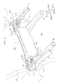
- a vehicle front structure 100 mainly has upper members 1, 1, side extensions 2, 2, side members 3, 3, damper housings 4, 4, damper housing supports 5, 5, a windshield lower 6, a cross member 7 (see FIG. 2 ), and a cowl top 8 (see FIG. 3 ).
- the upper member 1 is a steel member which is arranged at both right and left sides of the vehicle V and extends along the front-back direction.
- the upper member 1 has an approximately U-shaped main body section 11 which opens outside in the vehicle width direction, and a fixed section 12 which extends from an inside at a rear of the main body section 11 in the vehicle width direction to a damper housing 4 and is fixed to an upper end part of the damper housing 4.
- a front end side of the main body section 11 is fixed on a front side frame 90 arranged diagonally downward of the main body section 11 and extending along the front-back direction via a coupling section (not illustrated).
- a rear end side of the main body section 11 is fixed on a frond end of a front pillar 91.
- a portion (tip side) of the fixed section 12 exposes from a bore 51a in an approximately triangular shape formed in the damper housing support 5 described later. At the exposed portion, a round-shaped bore 12a is formed.
- the bore 12a is closed by a cap member (not illustrated).
- a bumper beam extension, a front bumper beam and the like are provided at a front end of the front side frame 90.
- the side extension 2 is a steel member which is arranged at both the right and left sides of the vehicle V and is fixed at a rear end side of the upper member 1. A rear end of the side extension 2 is fixed on the front end of the front pillar 91.
- the side member 3 is a steel member which is arranged at both the right and left sides of the vehicle V and transmits a collision load applied on the upper member 1 at a time of front collision to the front pillar 91.
- a front end side of the side member 3 is fixed on the main body section 11 and the fixed section 12 of the upper member 1, and a rear end side thereof is fixed on an upper end part of the side extension 2.
- the damper housing 4 is a steel member which is arranged at both the right and left sides of the vehicle V and accommodates to support the damper (not illustrated) therein.
- the damper housing 4 is arranged inside in the vehicle width direction at the rear end side of the upper member 1, and is arranged in front of both right and left ends of the cross member 7.
- An outer end part of the damper housing 4 is fixed inside the main body section 11 of the upper member 1 in the vehicle width direction, and a lower end part thereof is fixed on the front side frame 90.
- a bore 41a is formed in an upper surface 41 of the damper housing 4, through which an upper end part of the damper is exposed outside.
- the fixed section 12 of the upper member 1 is provided to cover the bore 41a from above.
- the fixed section 12 of the upper member 1 constitutes the upper surface 41 of the damper housing 4.
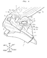
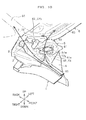
- the damper housing support 5 is a steel member which is arranged at both the left and the right sides of the vehicle V and couples the damper housing 4 and the cross member 7. As illustrated in FIG. 4 , the damper housing support 5 has a damper housing fixed section 51, a side wall section 52 and a vertical wall section 53.
- the damper housing fixed section 51 is a section which is fixed on the upper surface 41 of the damper housing 4. As illustrated in FIGS. 4 and 6 , a bore 51a is formed in the damper housing fixed section 51, through which the portion of the fixed section 12 of the upper member 1 is exposed.
- the upper surface 41 of the damper housing 4 and the upper surface of the damper housing fixed section 51 constitute a flow orientation surface on which outside air (air) from an outside air introduction port 81 of a cowl top 8 described later flows.
- the side wall section 52 is a section which extends downward and backward from a rear end part of the damper housing fixed section 51, and is fixed on a vertical wall section 72 of the cross member 7.
- the side wall section 52 extends along a rear end part of the damper housing 4 at a rear upper side of the rear end part.
- the side wall section 52 has a slope section 52a extending incliningly so as to position downward as extending backward from the rear end part of the damper housing fixed section 51, and a bottom wall section 52b extending backward from a rear end part of the slope section 52a and fixed on the cross member 7.
- the slope section 52a, the bottom wall section 52b and the vertical wall section 72 of the cross member 7 form a drain H in the right-left direction, and the drain H has a concave-shape seen in cross section.
- the bottom wall section 52b inclines to position downward as extending outside in the vehicle width direction.
- the vertical wall section 53 is a section which extends upward and backward from an inside of the damper housing fixed portion 51 in the vehicle width direction, and is fixed on the vertical wall section 72 of the cross member 7.
- the vertical wall section 53 is continuously formed inside the side wall section 52 in the vehicle width direction and closes inside the drain H in the vehicle width direction.
- the vertical wall section 53 functions as cutoff section which prevents in-flow water in the drain H from flowing inside in the vehicle width direction.
- a flange section 54 is formed extendingly to be fixed on the cross member 7 at a rear end parts of the bottom wall section 52b and the vertical wall section 53.
- the flange section 54 extends from an upper end part of the vertical wall section 53 to a right end part and the vicinity of the bottom wall section 52b in a direction perpendicular to the bottom wall section 52b and the vertical wall section 53 (the up-down direction and the right-left direction).
- the side wall section 52 and the vertical wall section 53 serves to drain the water flowing from the outside of the vehicle V to a side thereof by cooperating with the vertical wall section 72 of the cross member 7. Further, the side wall section 52 and the vertical wall section 53 form an approximately box-like structure (bag structure), thereby rigidity of the damper housing support 5 in the front-back direction and the up-down direction is improved.
- the damper housing 4 and the cross member 7 as rigid bodies are coupled by the side wall section 52 and the vertical wall section 53 to form a highly rigid body at a front of the vehicle.
- a collision load applied on the upper member 1 at the time of front collision can be smoothly transmitted to the damper housing 4, the damper housing support 5, the cross member 7 and the windshield lower 6. Therefore, the collision energy can be absorbed favorably and load burden applied on the side extension 2 and the side member 3 can be reduced.
- the windshield lower 6 is a long steel member in the right-left direction which is fixed on an upper end part of a dashboard lower 92 partitioning an engine room ER from a compartment CR and which extends forward from the upper end part to support a windshield 93 in a cantilever structure.
- the windshield lower 6 has a flange section 61 which extends in the front-back direction to be fixed on the dashboard lower 92, a vertical wall section 62 which extends upward from a front end of the flange section 61, and a side wall section 63 which extends forward from an upper end part of the vertical wall section 62 to support a lower end part of the windshield 93.
- the vertical wall section 62 is a section which is arranged backward from the vertical wall section 72 of the cross member 7 at a predetermined interval.
- a blower inlet port 62a in an approximately rectangular shape opens at a right end part side of the vertical wall section 62.
- a blower B which supplies the outside air to the compartment CR (see FIG. 3 ) is coupled at a rear side of the blower inlet port 62a.
- both right and left ends of the side wall section 63 position above the damper housing support 5.
- the side wall section 63 and the windshield 93 are mutually fixed with an adhesive 94.
- a predetermined gap C is formed between a front end side of the side wall section 63 and the upper end part of the vertical wall section 53.
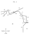
- the cross member 7 is a long steel member in the right-left direction which extends along the vehicle width direction and is arranged between the front pillars 91, 91 at both right and left sides via the side extension 2. As illustrated in FIG. 3 , the cross member 7 is fixed on a base end side (rear end side) of the windshield lower 6 to form a closed section K with the windshield lower 6. Thus, support rigidity at the base end side of the windshield lower 6 is enhanced.
- the cross member 7 has a lower flange section 71 of which the rear end side is fixed on the upper end part of the dashboard lower 92 and the side wall section 63 of the windshield lower 6, the vertical wall section 72 which extends upward from a front end of the lower flange section 71, and an upper flange section 73 which extends forward from an upper end of the vertical wall section 72 and is fixed on a rear end side of the side wall section 63.
- the vertical wall section 72 is a section which is formed such that an up-down size at both the right and left end sides is larger than an up-down size at a central side in the vehicle width direction.
- both right and left ends of the vertical wall section 72 face the side wall section 52 and the vertical wall section 53 of the damper housing support 5.
- a pair of outside air inlet ports 72a, 72b in an approximately rectangular shape open for passing the outside air at both right and left end sides of the vertical wall section 72.
- lower ends 72a1, 72b1 of the outside air inlet ports 72a, 72b position above the upper surface 41 of the damper housing 4 and the upper surface of the damper housing fixed section 51.
- the outside air inlet ports 72a, 72b position outside the vertical wall section 53 of the damper housing support 5 in the vehicle width direction.
- the blower inlet port 62a is provided at a position corresponding to the right outside air inlet port 72a.
- the blower inlet port 62a is provided to deviate to a right region with respect to a center line along the front-back direction passing through a center of the cross member 7 in the vehicle width direction.
- the blower inlet port 62a positions below the outside air inlet port 72a.
- the oblong closed section K is formed by the windshield lower 6 and the cross member 7, up and down positions of the blower inlet port 62a and the outside air inlet port 72a can be shifted.
- the blower inlet port 62a is provided at a position where the outside air inlet port 72a does not overlap the blower inlet port 62a seen from the front-back direction of the vehicle.
- the blower inlet port 62a is provided at the position where the outside air inlet port 72a does not overlap the blower inlet port 62a when the blower inlet port 62a is projected on the vertical wall section 72 of the cross member 7.
- the closed section K is formed in an oblong shape seen in vertical cross section, and functions as inlet passage through which the pair of right and left outside air inlet ports 72a, 72a communicate with the blower inlet port 62a.
- the cowl top 8 is a resin member which covers an opening 96 formed between the windshield lower 6 and a engine hood 95.
- the cowl top 8 is fixed on the windshield lower 6 to form, as it is called, a cowl box with the windshield lower 6.
- the outside air introduction port 81 which introduces the outside air from the outside of the vehicle V is formed through both right and left end sides of the cowl top 8.
- the vehicle front structure 100 according to the first embodiment of the invention is basically structured as described above and effects thereof will be explained below.
- the damper housing 4 since the damper housing 4 is fixed inside the upper member 1 in the vehicle width direction and is coupled with the cross member 7 via the damper housing support 5, the collision load applied on the upper member 1 via the front side frame 90 at the time of front collision (especially at the time of offset collision) is dispersively transmitted to the cross member 7 via the damper housing 4 and the damper housing support 5. Further, since the cross member 7 forms the closed section K with the windshield lower 6, the collision load transmitted to the cross member 7 is also transmitted to the windshield lower 6.
- the collision load applied on the upper member 1 is dispersed as a load applied on a side section of a body such as the side member 3, the side extension 2 and the front pillar 91, and as a load applied on a center section of the body such as the cross member 7 and the windshield lower 6.
- the damper housing 4 as a rigid body is coupled with the cross member 7 by the side wall section 52 and the vertical wall section 53 to form the highly rigid body at the front of the vehicle, the collision load applied on the upper member 1 can be smoothly transmitted to the damper housing 4, the damper housing support 5, the cross member 7 and the windshield lower 6. This makes it possible to absorb the collision energy favorably and the load burden applied on the side extension 2 and the side member 3 can be reduced.
- the side wall section 52 of the damper housing support 5 extends downward and backward from the rear end part of the damper housing fixed section 51 along the rear end part of the damper housing 4 to be fixed on the cross member 7. Further, the vertical wall section 53 of the damper housing support 5 extends upward and backward from the inside of the damper housing fixed section 51 in the vehicle width direction to be fixed on the cross member 7. Therefore, when the damper housing 4 moves backward at the time of front collision, the collision load along the front-back direction is transmitted to the side wall section 52 and the vertical wall section 53. Accordingly, the collision energy can be absorbed after the side wall section 52 and the vertical wall section 53 are crushed, and the collision load can be transmitted over the cross member 7 via the side wall section 52 and the vertical wall section 53.
- the damper housing 4 is fixed on the upper member 1 and is fixed to the cross member 7 forming the closed section K with the windshield lower 6 via the side wall section 52 and the vertical wall section 53 of the damper housing support 5.
- the damper housing 4 is supported by the two members, that is, the upper member 1 and the cross member 7, and the rigidity of the damper housing support 5 in the front-back direction and the up-down direction is improved by the side wall section 52 and the vertical wall section 53. Therefore, support rigidity of the damper housing 4 enhances.
- the damper housing 4 is difficult to deform due to a load in the up-down direction applied on a damper, and the rigidity of the front of the body enhances, leading to the following effects:
- the vehicle front structure 100 of the invention will be compared with a vehicle front structure 200 of the prior art.
- the vehicle front structure 200 of the prior art has a dashboard upper 240 which extends forward from an upper end part of a dashboard lower 230 partitioning an engine room 210 from a compartment 220, a windshield lower 260 which supports an lower end part of the windshield 250, and a cowl top 280 which covers an outside air inlet port 270 formed between the dashboard upper 240 and the windshield lower 260.
- An outside air inlet bore 280A is formed in the cowl top 280, and a blower inlet port 260A which is coupled to a blower (not illustrated) is formed in the windshield lower 260.
- the concave-shaped drain H seen in cross section is formed along the right-left direction by the slope section 52a, the bottom wall section 52b of the side wall section 52 and the vertical wall section 72 of the cross member 7.
- the vertical wall section 53 (see FIG. 5 ) is provided inside the drain H in the vehicle width direction. Therefore, the water flowing from the outside of the vehicle V is directly introduced to the side wall section 52 of the damper housing support 5 or is introduced to the side wall section 52 via the vertical wall section 72 of the cross member 7. Then, the water is drained to the side section of the vehicle V via the bottom wall section 52b of the side wall section 52 and the gas can be separated from the liquid properly.
- the blower inlet port 62a is provided to the position where the outside air inlet port 72a does not overlap the blower inlet port 62a seen in the front-back direction of the vehicle. Therefore, even if passing through the outside air inlet port 72a, the water hits on the vertical wall section 62 of the windshield lower 6 and the water cannot flow in the blower inlet port 62a, resulting in an excellent property on gas-liquid separation.
- the gas can be separated from the liquid favorably by the side wall section 52, the vertical wall section 53 of the damper housing support 5, the vertical wall section 72 of the cross member 7 and the vertical wall section 62 of the windshield lower 6. Therefore, the dashboard upper 240 having the large section size which has been used can be omitted, and the windshield lower 6, the cowl top 8 and the like can be lowered accordingly. Thus, front visibility of the vehicle V can be promoted.
- the conventional vehicle front structure 200 since the conventional vehicle front structure 200 has the dashboard upper 240 having the large section size, the clearance between the dashboard upper 240 and the engine 300 in the front-back direction of the vehicle is shortened. Therefore, the dashboard upper 240 and the windshield lower 260 cannot be arranged forward. Thus, the windshield 250 cannot be projected forward and compartment space cannot be expanded.
- the dashboard upper 240 having the large section size which has been used previously can be omitted, the windshield lower 6, the cowl top 8 and the like can be arranged forward accordingly. Therefore, since the windshield 93 can be projected forward, the compartment space can be expanded.
- the windshield 93 is supported at the front end side of the windshield lower 6 in the cantilever structure and the closed section K is formed by the windshield lower 6 and the cross member 7 at the base end side (rear end side) of the windshield lower 6. Therefore, the support rigidity at the base end side is improved and the front end side of the windshield lower 6 is easily bent to the load from above, thereby the load from above can be absorbed in a good manner.
- the dashboard upper 240 having the large section size can be omitted, no member impedes deformation of the windshield lower 6 below around the center section of the windshield lower 6 in the vehicle width direction. Therefore, collision absorption stroke of the windshield lower 6 to the load from above can be reserved, thereby the load from above can be absorbed much better.
- the gap C is formed between the front end side of the windshield lower 6 and the upper end part of the vertical wall section 53 of the damper housing support 5. Therefore, the collision absorption stroke of the windshield lower 6 to the load from above can be reserved even at both the end sides of the windshield lower 6 in the vehicle width direction, thereby the load from above can be absorbed much better.
- the dashboard upper 240 can be omitted, the weight of the body can be reduced.
- the windshield lower 6 and the like constituting the vehicle front structure 100 of the embodiment are made of the steel members, the invention is not limited thereto and they may be formed by press-forming a metallic plate such as an aluminum plate.
- blower inlet port 62a of the embodiment is provided at the position corresponding to the right outside air inlet port 72a, the invention is not limited thereto, and it may be provided at a position corresponding to the left outside air inlet port 72b or between the right and the left side outside air inlet ports 72a and 72b (for example, the center of the windshield lower 6 in the vehicle width direction).
- blower inlet port 62a and the outside air inlet ports 72a, 72b of the invention are formed in a rectangular shape, the invention is not limited thereto and they may be formed in other shapes such as in a circular shape.
- a vehicle front structure 110 according to a second embodiment of the invention will be explained.
- the structures of the damper housing support 5, the windshield lower 6, the cross member 7 and the cowl top 8 are different from those of the first embodiment.
- the second embodiment is different from the first embodiment in that a reinforcement member 9, a wiper device 10 and a covering member S are further provided.
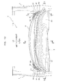
- FIG. 13 is a schematic perspective view seen down from a diagonally front left side of the vehicle front structure without the cowl top and the windshield lower.
- the damper housing support 5 has the damper housing fixed section 51, the side wall section 52 and the vertical wall section 53.
- the damper housing fixed section 51 is a portion which is fixed on the upper surface 41 of the damper housing 4.
- the upper surface 41 of the damper housing 4 and the upper surface of the damper housing fixed section 51 constitute a flow orientation surface on which the outside air from the outside air introduction port 81 and an outside air inlet bore 85 of the cowl top 8 described later flows.
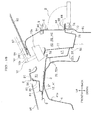
- FIG. 12 is a partial plan view of the vehicle front structure according to the second embodiment of the invention
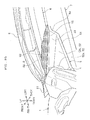
- FIG. 16 is an end view along V-V line in FIG. 12 .
- the side wall section 52 is a section which extends downward and backward from the rear end part of the damper housing fixed section 51.
- the side wall section 52 positions behind the rear end part at an upper side of the damper housing 4 and extends along the rear end part.
- the side wall section 52 has the slope section (front wall section) 52a extending incliningly so as to position downward as extending backward from the rear end part of the damper housing fixed port 51, and the bottom wall section 52b extending backward from the lower end part of the slope section 52a and fixed on the cross member 7.
- the bottom wall section 52b inclines to position downward as extending outside in the vehicle width direction.
- the vertical wall section 53 is a linear section which extends backward from the inside of the damper housing fixed portion 51 in the vehicle width direction.
- the vertical wall section 53 inclines to position inside in the vehicle width direction (the central side of the cross member 7 in the vehicle width direction) as extending backward from a front.
- the vertical wall section 53 is formed continuously inside the side wall section 52 in the vehicle width direction.
- a concave-shaped first drain H1 seen in vertical cross section is formed in the right-left direction by the slope section 52a, the bottom wall section 52b, the vertical wall section 53 and a front side vertical wall section 77 of the cross member 7.
- an approximately L-shaped cross section is formed by the bottom wall section 52b and the vertical wall section 53.
- a flange section 54 fixed on the cross member 7 is formed on the rear end part of the bottom wall section 52b and the vertical wall section 53.
- the flange section 54 extends in the direction (the up-down direction or the right-left direction) perpendicular to the bottom wall section 52b and the vertical wall section 53.
- a flange section 55 is formed extendingly inside in the vehicle width direction on the upper end part of the vertical wall section 53.
- FIG. 14 is an end view along IV-IV line in FIG. 12 .
- the windshield lower 6 is a member which supports the windshield 93 from underneath.
- the windshield lower 6 has a flange section (second flange section) 64 which extends in the front-back direction to be fixed on a flange section 92a of the dashboard lower 92, a vertical wall section (rear wall section) 65 which extends upward from a front end part of the flange section 64, and a side wall section (windshield support section) 66 which extends from an upper end part of the vertical wall section 65 toward the windshield 93 (forward).
- the side wall section 66 is fixed on a lower surface of the windshield 93 with the adhesive 94.
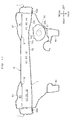
- FIG. 15A is a perspective view where the windshield lower is seen down from a diagonally rear side
- FIG 15B is an end view along VII-VII line in FIG. 15A .
- both right and left end parts of the windshield lower 6 are fixed on the right and left upper member 1, respectively.
- the right and left end parts of the windshield 6 may be fixed on the front pillar 91, respectively.
- a pair of bulged sections 67 which bulge (project) upward with respect to a rear part on a central side are provided at both the right and left end sides of the windshield lower 6, respectively.
- a blower inlet port 68 in an approximately rectangular shape opens at a rear part on a lower end side of the right bulged section 67.
- a blower B which supplies the outside air to the compartment CR is coupled with a rear of the blower inlet port 68.
- the cross member 7 is fixed on a base end part side (rear end part side) of the windshield lower 6 and forms a central closed section K1 with the windshield lower 6, the central closed section K1 extending in the vehicle width direction.
- the cross member 7 has a lower flange section (third flange section) 74, a rear side vertical wall section 75 extending downward from a front end part of the lower flange section 74, a side wall section 76 extending forward from a lower end part of the rear side vertical wall section 75, a front side vertical wall section 77 extending upward from a front end part of the side wall section 76, and an upper flange section 78 extending diagonally upward from an upper end part of the front side vertical wall section 77.
- the lower flange section 74 is sandwiched in the up-down direction between the flange section 92a of the dashboard lower 92 partitioning the engine room ER from the compartment CR and the flange section 64 of the windshield lower 6, and is fixed by a fixing manner such as welding.
- the upper flange section 78 is fixed on the side wall section 66 of the windshield lower 6 by the fixing manner such as welding. As illustrated in FIG. 16 , both right and left end parts of the front side vertical wall section 77 face the side wall section 52 of the damper housing support 5.
- FIG. 17 is an end view along VI-VI line in FIG. 12 .
- the side wall section (bottom wall section) 76 is formed in a tight lipped mouth shape with both ends turned down seen in vertical cross section and positions above a brake master cylinder 97 attached in the dashboard lower 92.
- a circular-shaped attachment bore 92b (see a two-dot chain line in FIG. 17 ) for attaching the brake master cylinder 97 is formed at a left lower part of the dashboard lower 92.
- the side wall section 76 has a runoff 76a projecting upward at a corresponding position to the brake master cylinder 97 in the up-down direction.
- a pair of inclined planes 76b which incline downward toward the outside in the vehicle width direction are formed consecutively at both right and left sides of the runoff 76a.
- Both right and left end parts of the cross member 7 are fixed on the upper member 1 and the front pillar 91, respectively (only a fixed state with the upper members 1 is illustrated in FIG. 17 ).
- the reinforcement member 9 is a steel member which is provided at both the end sides of the cross member 7 in the vehicle width direction respectively and extends to the upper member 1 and the front pillar 91.
- the reinforcement member 9 is arranged between the bulged section 67 of the windshield lower 6 and the cross member 7, and has a function to reinforce both the end sides of the windshield lower 6 in the vehicle width direction.
- a front flange section 9a is formed which is fixed on the upper flange section 78 of the cross member 7 at a front end part of the reinforcement member 9.
- a rear flange section 9b is formed which is fixed on an inner surface of the bulged section 67 at a rear end part of the reinforcement member 9.
- An outside air inlet port 9C in an approximately rectangular shape opens for passing the outside air at a central part of the reinforcement member 9.
- a projection section 9d is formed to project upward at an opening edge part of the outside air inlet port 9c.
- the reinforcement members 9, the cross member 7 and the bulged sections 67 of the windshield lower 6 form an end closed section K2 extending in the vehicle width direction at both the right and left sides, respectively.
- the central closed section K1 and the end closed section K2 communicate to each other (see FIG. 17 ).
- the cowl top 8 is a hat-shaped resin member covering the opening 96 formed between the engine hood 95 and the windshield lower 6. A rear end part on the central side of the cowl top 8 in the vehicle width direction is placed on an upper surface of the windshield 93. As illustrated in FIG. 16 , both the right and left end sides of the cowl top 8 are arranged above the damper housing support 5. As illustrated in FIG. 18 , the outside air introduction port 81 in an approximately rectangular shape for introducing the outside air from the outside of the vehicle V and a wiper opening 82 for exposing a wiper shaft 10b of a wiper device 10 to the outside are formed respectively on an upper surface of the cowl top 8 at both the right and left end sides.
- An opening for operation 83 facing the upper surface 41 of the damper housing 4 and an upper surface of the damper housing support 5 is formed on a front surface of the cowl top 8 at both the right and left end sides, respectively.
- the opening for operation (first opening) 83 positions in front of a first inlet passage R1 and is closed by a resin damper attachment lid 84.
- the damper attachment lid 84 is detachably provided on the opening for operation 83. In case of a removing/attaching operation for the damper or a maintenance operation, removing the damper attachment lid 84 allows a user to perform the removing/attaching operation for the damper and the maintenance operation easily.
- the outside air introduction bore 85 in a form of lattice is formed on an upper surface of the damper attachment lid 84, facing the upper surface 41 of the damper housing 4 and the upper surface of the damper housing support 5.
- the outside air introduction bore (second opening) 85 has a function to introduce the outside air to the first inlet passage R1.
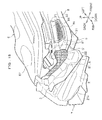
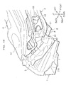
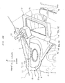
- FIG. 18 is a partially enlarged perspective view seen down from a diagonally front right side of the right portion in the vehicle front structure with an outer lid member.
- FIG. 19 is a partially enlarged perspective view seen down from the diagonally front right side of the right portion in the vehicle front structure without the outer lid member.
- FIG. 20 is a partially enlarged perspective view seen up from a diagonally front left side of the right portion in the vehicle front structure with an inner lid member.
- FIG. 21 is a schematic perspective view seen down from a diagonally front side of the right portion in the vehicle front structure without the cowl top and the windshield lower.
- the covering member S has an outer lid member S1, an inner lid member S2 and a sealing material S3.
- the outer lid member S1 is made of, for example, a plate-like rubber and has a function to close a gap G1 formed between the cowl top 8 and the side member 3.
- the inner lid member S2 is made of, for example, a plate-like rubber and has a function to close a gap G2 between the vertical wall section 53 of the damper housing support 5 and the cowl top 8 and between the vertical wall section 53 of the damper housing support 5 and the windshield lower 6. As illustrated in FIG.
- the sealing material S3 is disposed on upper surfaces of the side member 3 and the damper housing support 5. As illustrated in FIGS. 18 to 21 , the sealing material S3 has a function to seal liquid-tightly and airtightly between the outer lid member S1 and the side member 3, between the cowl top 8 and the damper housing fixed section 51, and between the inner lid member S2 and the vertical wall section 53.
- the covering member S can restrain that hot air from the engine room ER flows to the first inlet passage R1 and that the water flows from the outside of the vehicle to the first inlet passage R1.
- the first inlet passage (outside air introduction passage) R1 is formed above the damper housing support 5 and is provided at both the right and left sides of the vehicle V, respectively.
- the first inlet passage R1 extends in the front-back direction and corresponds to a space from the outside air introduction port 81 and the outside air introduction bore 85 to the outside air inlet port 9c.
- the cowl top 8, the damper housing support 5, the windshield lower 6, the reinforcement member 9, the covering member (see FIGS. 18 to 21 ), and the upper member 1 (see FIG. 17 ) form the first inlet passage R1. Further, as illustrated in FIG.
- a second inlet passage R2 extends in the right-left direction, which lets the first inlet passage R1 at both the right and left sides communicate via the central closed section K1 and the end closed section K2.
- Such a structure enables the outside air introduced from the outside air introduction port 81 and the outside air introduction bore 85 at a front right side of the cowl top 8 to flow through the first inlet passage R1 and the outside air inlet port 9c at a right side and to be delivered from the blower inlet port 68 toward the blower B (see FIGS. 12 and 16 ).
- the outside air introduced from the outside air introduction port 81 and the outside air introduction bore 85 at a front left side of the cowl top 8 flows through the first inlet passage R1 and the outside air inlet port 9c at a left side, then, further flows from the left side to the right side in the second inlet passage R2. Consequently, the outside air is delivered from the blower inlet port 68 toward the blower B (see FIGS. 12 , 16 and 17 ).
- the central closed section K1 and the end closed section K2 also function as a second drain H2 by which the water passing the outside air inlet port 9c is drained to the side section of the vehicle V.
- the blower inlet port 68, the blower B, the brake master cylinder 97, the attachment bore 92b, the runoff 76a and the like are positioned with the right and left sides reversed.
- FIG. 22 is a partially enlarged perspective view seen down from a left side around a right wiper device.
- the wiper device 10 is a device which is arranged in the first inlet passage R1 and wipes off water, snow etc. on the windshield 93.
- the damper housing support 5 and the cross member 7 are arranged under the wiper device 10.
- the wiper device 10 has a wiper base 10a and a wiper shaft 10b which is attached on an upper part of the wiper base 10a and extends upward.
- the wiper shaft 10b exposes from the wiper opening 82 of the cowl top 8 to an outside of the first inlet passage R1.
- a wiper blade (not illustrated) which slidingly contacts on the windshield 93 is attached via a wiper link 10f and a wiper arm (not illustrated) on a top end of the wiper shaft 10b.
- the wiper device 10 is fixed on the upper surface of the damper housing support 5, an inner surface of the windshield lower 6 and the like via a bracket (not illustrated).
- a cut-out section 21a is formed at a lower part of a rear end of the side extension 2.
- the cut-out section 21a communicates with the first drain H1 and the second drain H2.
- the water flowing from the first drain H1 and the second drain H2 is drained to the side section of the vehicle V through the cut-out section 21a.
- the vehicle front structure 110 according to the second embodiment of the invention is basically structured as described above. Next, the effects thereof will be explained.
- the vertical wall section 53 extends linearly from the inside of the damper housing fixed section 51 in the vehicle width direction toward the central side of the cross member 7 in the vehicle width direction, and inclines to position inside in the vehicle width direction as extending backward from the front. Therefore, the load applied on the upper part of the damper housing 4 in the front-back direction and the right-left direction at a time of driving and turning is transmitted to the cross member 7 via the vertical wall section 53. This leads to higher support rigidity of the damper housing 4 and improves the operation stability.
- the approximately L-shaped cross section is formed by the vertical wall section 53 and the bottom wall section 52b, rigidity of the damper housing support 5 which couples the damper housing 4 and the central side of the cross member 7 in the vehicle width direction can be enhanced, resulting in the higher support rigidity of the damper housing 4.
- both the ends of the windshield lower 6 in the vehicle width direction are fixed on the upper member 1, respectively, torsional rigidity of the windshield lower 6 can be improved.
- JPS6430888A discloses a structure in which vehicle torsional rigidity is decreased due to an open cross section where a cowl opens forward.
- the central closed section K1 extending in the vehicle width direction is formed by the windshield lower 6 and the cross member 7, and the end closed section K2 extending in the vehicle width direction is formed by the reinforcement member 9, the cross member 7 and the windshield lower 6. Therefore, the vehicle torsional rigidity can be improved compared with the structure disclosed in JPS6430888A.
- JPS6430888A an air intake box having an outside air introduction port is provided on a right damper housing, a space section communicating with the air intake box is formed at a right end part of the cowl, and a wiper motor is attached at a left end part of the cowl via an auxiliary plate. Therefore, the structure is such that the outside air is introduced from only the right end part of the cowl and the outside air cannot be introduced from the left end part of the cowl.
- the first inlet passage R1 is provided both the right and left sides of the vehicle V respectively, and the second inlet passage R2 communicating with the first inlet passage R1 at both the right and left sides is provided to introduce the outside air from both the right and left sides of the vehicle V. Therefore, outside air introduction amount can be increased compared with the structure disclosed in JPS6430888A.
- the first inlet passage R1 is formed above the damper housing support 5, no member projecting to the engine room ER side is provided at the central side of the cross member 7 in the vehicle width direction.
- the engine hood 95 can be positioned lower, resulting in improvement of visibility at the front of the vehicle.
- the wiper device 10 since the wiper device 10 is arranged in the first inlet passage R1, the water flowing in the first inlet passage R1 hits on the wiper device 10 while the outside air flows to circumvent the wiper device 10. Therefore, in-flow water to the blower B can be restrained and a decline of the outside air introduction amount can be prevented.
- the opening for operation 83 and the damper attachment lid 84 which is detachably attached on the opening for operation 83 are provided at both end parts of the cowl top 8 in the vehicle width direction, the removing/attaching operation for the damper and the maintenance operation can be performed easily by taking off the damper attachment lid 84 from the cowl top 8.
- the outside air introduction bore 85 is formed in the damper attachment lid 84, the outside air is introduced from the outside air introduction bore 85 in addition to the outside air introduction port 81. Therefore, the outside air introduction amount can be increased.
- the damper housing support 5, the windshield lower 6, the reinforcement member 9, the covering member S and the upper member 1 front-back length of the first inlet passage R1 can be elongated and a width size of the first inlet passage R1 can be broadened.
- the in-flow water from the outside air introduction port 81 of the cowl top 8 drops on the damper housing support 5 and the cross member 7 to be drained on the way to the first inlet passage R1. Therefore, the gas-liquid separation is improved and power consumption of the blower B (air conditioner) can be reduced by keeping the outside air introduction amount sufficiently.
- the first drain H1 extending in the vehicle width direction is formed by the side wall section 52, the vertical wall section 53 of the damper housing support 5 and the front side vertical wall section 77 of the cross member 7, the water (such as rain or the water at a time of car washing) can be drained outside the vehicle.
- the damper housing support 5 and the cross member 7 are disposed under the wiper device 10, the water hit on the wiper device 10 is drained outside the vehicle via the damper housing support 5 and the cross member 7.
- the side wall section 76 of the cross member 7 has the runoff 76a which projects upward at the corresponding position to the brake master cylinder 97 in the up-down direction. Therefore, the cross member 7 can be arranged downward to bring close to the brake master cylinder 97 compared with the side wall section 76 formed flat, and the engine hood 95 can be positioned lower accordingly.
- the side wall section 76 of the cross member 7 has the right and left pair of the inclined planes 76b which incline so as to position downward as extending from both the right and left sides of the runoff 76a to the outside in the vehicle width direction. Therefore, the water on the side wall section 76 of the cross member 7 is easily drained to the side section of the vehicle V by self-weight.
- the bulged section 67 which bulges upward with respect to the center in the vehicle width direction is formed on both the ends of the windshield lower 6 in the vehicle width direction, respectively.
- the reinforcement member 9 is disposed between the bulged section 67 of the windshield lower 6 and the cross member 7. Therefore, an arrangement space for the wiper device 10 can be reserved between the bulged section 67 of the windshield lower 6 and the reinforcement member 9.
- the lower flange section 74 of the cross member 7 is sandwiched in the up-down direction between the flange section 92a of the dashboard lower 92 and the flange section 64 of the windshield lower 6, and is fixed by the fixing manner such as welding. Therefore, the cross member 7 does not have a portion projecting backward with respect to the dashboard lower 92.
- the air conditioner and the like can be arranged in front of the compartment CR, the compartment CR can be expanded, and the windshield lower 6 can be positioned lower. Consequently, an arrangement space for a defroster nozzle which has an optimum shape for satisfactory defrosting performance can be reserved.
Landscapes
- Engineering & Computer Science (AREA)
- Chemical & Material Sciences (AREA)
- Combustion & Propulsion (AREA)
- Transportation (AREA)
- Mechanical Engineering (AREA)
- Body Structure For Vehicles (AREA)
Abstract
The vehicle front structure 100 has a windshield lower 6, a cross member 7 fixed on the windshield lower 6, an upper member 1 extending in a front-back direction of a vehicle, a damper housing 4 fixed inside the upper member 1 in a vehicle width direction and arranged in front the cross member 7, and a damper housing support 5 coupling the cross member 7 with the damper housing 4. A closed section K is formed by the windshield lower 6 and the cross member 7. The damper housing support 5 has a damper housing fixed section 51 which is fixed on an upper surface 41 of the damper housing 4 and a vertical wall section 53 which extends backward from an inside of the damper housing fixed section 51 in the vehicle width direction and is fixed on the cross member 7.
Description
- The invention relates to a vehicle front structure.
- Conventionally, a vehicle front structure has been known in which a collision load generated at a time of front collision is transmitted dispersively.
- For example,
Patent Literature 1 discloses providing first members between a right and left pair of front side frames extending in a front-back direction of a vehicle and front end parts of a right and left pair of suspension towers arranged outside the front side frames respectively, and transmitting a collision load applied on the front side frames to the suspension towers dispersively via the first members.Patent Literature 1 further discloses providing second members between rear end parts of the suspension towers and a front end part of a cowl box supporting a lower end part of a windshield respectively, and transmitting the collision load transmitted to the suspension towers to the cowl box via the second members. - Still further,
Patent Literature 1 discloses disposing a suspension tower bar between both the right and left side suspension towers and providing the first members in an inverted v-shape tapering off toward a front of the vehicle seen in planar view. Accordingly, the suspension towers are displaced in a vehicle width direction at the time of front collision to transmit the collision load along an axial direction of the suspension tower bar. This causes plastic deformation in the suspension tower bar along the axial direction thereof and collision energy is absorbed. - Patent Literature 1:
JP2007-230490 A - However, in the invention disclosed in
Patent Literature 1, since the second members are provided between the suspension towers and the cowl box, if the suspension towers are displaced in the vehicle width direction, a coupling section side of the second members with suspension towers are displaced in the vehicle width direction with respect to the coupling sections with the cowl box. Thus, there arises problems such that the collision load is difficult to be transmitted from the second members to the cowl box and the second members themselves do not contribute to the absorption of the collision energy. - The present invention is invented from such a point of view and aims to provide a vehicle front structure which is capable of achieving satisfactory shock absorption.
- To solve the above problems, the invention provides a vehicle front structure comprising: a windshield lower that supports a windshield from underneath; a cross member that is fixed on the windshield lower and extends in a vehicle width direction; an upper member that is fixed on a front end part of a front pillar and extends in a front-back direction of a vehicle; a damper housing that is fixed inside the upper member in the vehicle width direction and is arranged in front of the cross member to attach a damper; and a damper housing support that couples the cross member with the damper housing, wherein the windshield lower and the cross member form a closed section, and the damper housing support has a damper housing fixed section that is fixed on an upper surface of the damper housing and a vertical wall section that extends backward from an inside of the damper housing fixed section in the vehicle width direction and is fixed on the cross member.
- According to the invention, the damper housing is fixed inside the upper member in the vehicle width direction and is coupled with the cross member via the damper housing support. Therefore, a collision load applied on the upper member at a time of front collision is transmitted dispersively to the cross member via the damper housing and the damper housing support. Further, since the cross member forms the closed section with the windshield lower, the collision load transmitted to the cross member is also transmitted to the windshield lower.
- Further, according to the invention, the vertical wall section of the damper housing support extends backward from the inside of the damper housing fixed section in the vehicle width direction to be fixed on the cross member. Therefore, if the damper housing moves backward at the time of front collision, the collision load along the front-back direction of the vehicle is transmitted to the vertical wall section. This causes the vertical wall section to be crushed, thereby collision energy can be absorbed and the collision load can be transmitted over the cross member by the vertical wall section.
- Still further, according to the invention, the damper housing is fixed on the upper member and is coupled with the cross member forming the closed section with the windshield lower via the damper housing support. Therefore, support rigidity of the damper housing enhances, and, improvement of ride quality, operation stability, and restraint of vehicle oscillation can be achieved.
- Moreover, according to the invention, since the windshield lower and the cross member form the closed section, a dashboard upper having a large section size is not needed and a compartment space can be expanded.
- Further, the damper housing support further has a side wall section preferably that extends downward and backward from a rear end part of the damper housing fixed section to extend along a rear end part of the damper housing and is fixed on the cross member.
- According to the structure, the side wall section of the damper housing support extends downward and backward from the rear end part of the damper housing fixed section which is fixed on the upper surface of the damper housing along the rear end part of the damper housing, and is fixed on the cross member. Therefore, if the damper housing moves backward at the time of front collision, the collision load along the front-back direction of the vehicle is also transmitted to the side wall section in addition to the vertical wall section. This causes the side wall section to be crushed, the collision energy can be absorbed much better, and the collision load can be transmitted much better over the cross member by the side wall section.
- Further, the invention further has a dashboard lower preferably that separates an engine room from a compartment, wherein the windshield lower is fixed on an upper end part of the dashboard lower and extends forward from the upper end part of the dashboard lower to support the windshield in a cantilever structure, and the cross member is fixed on the dashboard lower side of the windshield lower.
- According to the structure, the windshield lower extends forward from the upper end part of the dashboard lower to support the windshield in the cantilever structure, and forms the closed section with the cross member at the dashboard lower side of the windshield lower to improve the support rigidity at the base end side of the windshield lower. Therefore, the front end side of the windshield lower is easily bent due to the load from above and the load from above can be absorbed favorably.
- Further, a front end side of the windshield lower positions above the damper housing support, and a gap is formed between the front end side of the windshield lower and an upper end part of the vertical wall section, preferably.
- According to the structure, since the gap is formed between the front end side of the windshield lower and the upper end part of the vertical wall section, a collision absorption stroke of the windshield lower to the load from above can be reserved and the load from above can be absorbed well.
- Further, the vertical wall section preferably extends linearly from an inside of the damper housing fixed section in the vehicle width direction to a central side of the cross member in the vehicle width direction and inclines to position at the inside in the vehicle width direction as extending backward from a front.
- According to the structure, the vertical wall section extends linearly from the inside of the damper housing fixed section in the vehicle width direction to the central side of the cross member in the vehicle width direction and inclines to position at the inside in the vehicle width direction as extending backward from the front. Therefore, the load applied on an upper part of the damper housing in the front-back direction and the right-left direction at a time of driving and turning is transmitted to the cross member via the vertical wall section. This leads to higher support rigidity of the damper housing and improves the operation stability.
- Further, the side wall section preferably has a front wall section that extends downward from the rear end part of the damper housing fixed section and extends along the rear end part of the damper housing, and a bottom wall section that extends backward from a lower end part of the front wall section and inclines to position downward as extending outside in the vehicle width direction to be fixed on the cross member, the vertical wall section is continuous inside the front wall section and the bottom wall section in the vehicle width direction, the front wall section, the bottom wall section, the vertical wall section and the cross member forms a drain extending in the vehicle width direction, and the vertical wall section and the bottom wall section forms an approximately L-shaped cross section.
- According to the structure, since the approximately L-shaped cross section is formed by the vertical wall section and the bottom wall section, the rigidity of the damper housing support which couples the damper housing and the central side of the cross member in the vehicle width direction is improved and the support rigidity of the damper housing can be enhanced. Further, since the front wall section, the bottom wall section, the vertical wall section and the cross member form the drain extending in the vehicle width direction, water (such as rain and water at a time of car washing) can be drained outside the vehicle.
- Further, the damper housing support preferably is arranged at both right and left sides, a right and left pair of outside air introduction passages that extends in the front-back direction to introduce outside air are formed above the damper housing support, and the closed section lets the right and left pair of outside air introduction passages communicate.
- According to the structure, since the outside air introduction passages which introduce the outside air are formed above the damper housing support, there is no member projecting to an engine room side at the central side of the cross member in the vehicle width direction. Therefore, an engine hood can be positioned lower and front visibility of the vehicle can be enhanced. Further, since the outside air is introduced from both the right and left sides, outside air introduction amount can be sufficiently kept by expanding an outside air introduction passage.
- Further, a bulged section that bulges upward with respect to a center in the vehicle width direction is preferably formed at both ends of the windshield lower in the vehicle width direction, a right and left pair of reinforcement members are further provided, which are provided at both ends of the cross member in the vehicle width direction and are arranged between the bulged section of the windshield lower and the cross member, the cross member and the windshield lower form a central closed section that extends at the central side in the vehicle width direction, the cross member, the reinforcement member and the bulged section of the windshield lower form an end closed section that extends at both the end sides in the vehicle width direction; and the central closed section and the end closed section communicate to each other.
- According to the structure, the bulged section that bulges upward with respect to the center in the vehicle width direction is formed at both the ends of the windshield lower in the vehicle width direction, reinforcement members are arranged between the bulged section of the windshield lower and the cross member. Therefore, an arrangement space for a wiper device can be reserved between the bulged section of the windshield lower and the reinforcement members.
- Further, preferably, the front end side of the windshield lower positions above the damper housing support, a cowl top is further provided, which is arranged above the damper housing support to cover an opening formed between the windshield lower and an engine hood, and which has an outside air introduction port through which the outside air is introduced, a covering member is further provided, which seals between the damper housing support, the windshield lower and the cowl top, and the cowl top, the damper housing support, the windshield lower, the reinforcement member, the covering member and the upper member forms the outside air introduction passage.
- According to the structure, since the outside air introduction passage is formed by the cowl top, the damper housing support, the windshield lower, the reinforcement member, the covering member and the upper member, front-back length of the outside air introduction passage can be elongated and a width size of the outside air introduction passage can be expanded. Thus, in-flow water from the outside air introduction port of the cowl top drops on the damper housing support and the cross member to be drained on the way to the outside air introduction passage. Therefore, gas-liquid separation is improved and power consumption of a blower (air conditioner) can be reduced by keeping the outside air introduction amount sufficiently.
- Further, both the ends of the windshield lower in the vehicle width direction is preferably fixed on the upper member or the front pillar.
- According to the structure, since both the ends of the windshield lower in the vehicle width direction are fixed on the upper member or the front pillar, torsional rigidity of the windshield lower can be raised.
- Further, preferably, a first flange section is formed at the upper end part of the dashboard lower, the windshield lower has a second flange section that is arranged above the first flange section, a rear wall section that extends upward from a front end part of the second flange section, and a windshield support section that extends from an upper end part of the rear wall section toward the windshield, and a third flange section is formed to be sandwiched between the first flange section and the second flange section.
- According to the structure, since the third flange section is formed which is sandwiched between the first flange section of the dashboard lower and the second flange section of the windshield lower at the rear end of the cross member, the cross member does not have a portion which projects backward with respect to the dashboard panel. Thus, since the air conditioner and the like can be arranged in front of the compartment, a compartment space can be expanded, and since the windshield lower can be positioned lower, an arrangement space for a defroster nozzle which has an optimum shape for satisfactory defrosting performance can be reserved.
- Further, preferably, the cowl top has a first opening that is provided at both the ends in the vehicle width direction and faces the upper surface of the damper housing and a damper attachment lid that closes the first opening and is detachably provided on the first opening, and the damper attachment lid has a second opening that faces the upper surface of the damper housing.
- According to the structure, the cowl top has the first opening that is provided at both the ends in the vehicle width direction and faces the upper surface of the damper housing and the damper attachment lid that closes the first opening and is detachably provided on the first opening, and the damper attachment lid has the second opening that faces the upper surface of the damper housing. Therefore, the outside air can be introduced through the second opening in addition to the outside air introduction port, and the outside air introduction amount can be increased. Further, a removing/attaching operation for a damper and a maintenance operation can be performed easily by detaching the damper attachment lid from the cowl top.
- Further, a wiper device is preferably arranged in the outside air introduction passage.
- According to the structure, since the wiper device is arranged in the outside air introduction passage, in-flow water in the outside air introduction passage hits on the wiper device while the outside air flows to circumvent the wiper device. Thus, water flow to the blower can be restrained and decrease of the outside air introduction amount can be prevented.
- Further, the damper housing support and the cross member are preferably arranged under the wiper device.
- According to the structure, since the damper housing support and the cross member are arranged under the wiper device, the water hit on the wiper device is drained outside the vehicle via the damper housing support and the cross member.
- Further, preferably, a brake master cylinder is attached in the dashboard lower, the cross member has a bottom wall section and is arranged above the brake master cylinder, and the bottom wall section has a runoff that projects upward at a corresponding position to the brake master cylinder in an up-down direction, and a right and left pair of inclined planes that incline to position downward as extending from the runoff to an outside in the vehicle width direction.
- According to the structure, the bottom wall section of the cross member has the runoff which projects upward at the corresponding position to the brake master cylinder in the up-down direction. Therefore, the cross member can be arranged downward to bring close to the brake master cylinder compared with the bottom wall section formed flat, and the engine hood can be positioned lower accordingly. Further, the bottom wall section of the cross member has the right and left pair of the inclined planes which incline so as to position downward as extending from the runoff to the outside in the vehicle width direction. Therefore, the water on the bottom wall section of the cross member is easily drained to the side section of the vehicle by self-weight.
- The invention can provide a vehicle front structure which is capable of achieving satisfactory impact absorption.
-
-
FIG. 1 is a schematic general perspective view of a vehicle front structure according to a first embodiment of the invention; -
FIG. 2 is a schematic general perspective view of the vehicle front structure without a windshield lower; -
FIG. 3 is an end view along I-I line inFIG. 1 ; -
FIG. 4 is a partially enlarged perspective view ofFIG. 1 ; -
FIG. 5 is a partially enlarged perspective view seen from an arrow X direction illustrated inFIG. 1 ; -
FIG. 6 is an end view along II-II line inFIG. 5 ; -
FIG. 7 is an end view along III-III line inFIG. 5 ; -
FIG. 8 is a partially enlarged perspective view seen from an arrow Y direction illustrated inFIG. 1 ; -
FIG. 9 is a rear view of the vehicle front structure; -
Fig. 10 is a partially enlarged perspective view illustrating load transmission in the vehicle front structure schematically; -
FIG. 11 is a side end view illustrating a vehicle front structure in a prior art; -
FIG. 12 is a partial plan view of the vehicle front structure according to a second embodiment of the invention; -
FIG. 13 is a schematic perspective view seen down from a diagonally front left side of the vehicle front structure without a cowl top and a windshield lower; -
FIG. 14 is an end view along IV-IV line inFig. 12 ; -
FIG. 15A is a perspective view where the windshield lower is seen down from a diagonally rear side, andFIG 15B is an end view along VII-VII line inFIG. 15A ; -
Fig. 16 is an end view along V-V line inFIG. 12 ; -
FIG. 17 is an end view along VI-VI line inFIG. 12 ; -
Fig. 18 is a partially enlarged perspective view seen down from a diagonally front right side of a right portion in the vehicle front structure with an outer lid member; -
FIG. 19 is a partially enlarged perspective view seen down from the diagonally front right side of the right portion in the vehicle front structure without the outer lid member; -
FIG. 20 is a partially enlarged perspective view seen up from a diagonally front left side of the right portion in the vehicle front structure with an inner lid member; -
FIG. 21 is a schematic perspective view seen down from a diagonally front side of the right portion in the vehicle front structure without the cowl top and the windshield lower; and -
FIG. 22 is a partially enlarged perspective view seen down from a left side around a right wiper device. - A first embodiment of the invention will be explained in detail with reference to
FIGS. 1 to 10 . In the explanations, a same element is labeled with a same numeral and redundant explanations will be omitted. - Further, in the explanations, when a direction is indicated, front-back, right-left, and up-down directions of a vehicle V will be used as references. A "vehicle width direction" and a "right and left direction" have a same meaning.
- As illustrated in
FIGS. 1 to 3 , avehicle front structure 100 according to the first embodiment of the invention mainly hasupper members side extensions side members damper housings damper housing supports FIG. 2 ), and a cowl top 8 (seeFIG. 3 ). - As illustrated in
FIG. 1 , theupper member 1 is a steel member which is arranged at both right and left sides of the vehicle V and extends along the front-back direction. Theupper member 1 has an approximately U-shapedmain body section 11 which opens outside in the vehicle width direction, and a fixedsection 12 which extends from an inside at a rear of themain body section 11 in the vehicle width direction to adamper housing 4 and is fixed to an upper end part of thedamper housing 4. - A front end side of the
main body section 11 is fixed on afront side frame 90 arranged diagonally downward of themain body section 11 and extending along the front-back direction via a coupling section (not illustrated). A rear end side of themain body section 11 is fixed on a frond end of afront pillar 91. A portion (tip side) of the fixedsection 12 exposes from abore 51a in an approximately triangular shape formed in thedamper housing support 5 described later. At the exposed portion, a round-shapedbore 12a is formed. Thebore 12a is closed by a cap member (not illustrated). Further, a bumper beam extension, a front bumper beam and the like (not illustrated) are provided at a front end of thefront side frame 90. - As illustrated in
FIG. 1 , theside extension 2 is a steel member which is arranged at both the right and left sides of the vehicle V and is fixed at a rear end side of theupper member 1. A rear end of theside extension 2 is fixed on the front end of thefront pillar 91. - As illustrated in
FIG. 1 , theside member 3 is a steel member which is arranged at both the right and left sides of the vehicle V and transmits a collision load applied on theupper member 1 at a time of front collision to thefront pillar 91. A front end side of theside member 3 is fixed on themain body section 11 and the fixedsection 12 of theupper member 1, and a rear end side thereof is fixed on an upper end part of theside extension 2. - As illustrated in
FIG. 1 , thedamper housing 4 is a steel member which is arranged at both the right and left sides of the vehicle V and accommodates to support the damper (not illustrated) therein. As illustrated inFIG. 2 , thedamper housing 4 is arranged inside in the vehicle width direction at the rear end side of theupper member 1, and is arranged in front of both right and left ends of thecross member 7. An outer end part of thedamper housing 4 is fixed inside themain body section 11 of theupper member 1 in the vehicle width direction, and a lower end part thereof is fixed on thefront side frame 90. As illustrated inFIG. 6 , abore 41a is formed in an upper surface 41 of thedamper housing 4, through which an upper end part of the damper is exposed outside. The fixedsection 12 of theupper member 1 is provided to cover thebore 41a from above. In the embodiment, the fixedsection 12 of theupper member 1 constitutes the upper surface 41 of thedamper housing 4. - As illustrated in
FIG. 2 , thedamper housing support 5 is a steel member which is arranged at both the left and the right sides of the vehicle V and couples thedamper housing 4 and thecross member 7. As illustrated inFIG. 4 , thedamper housing support 5 has a damper housing fixedsection 51, aside wall section 52 and avertical wall section 53. - As illustrated in
FIG. 6 , the damper housing fixedsection 51 is a section which is fixed on the upper surface 41 of thedamper housing 4. As illustrated inFIGS. 4 and6 , abore 51a is formed in the damper housing fixedsection 51, through which the portion of the fixedsection 12 of theupper member 1 is exposed. - In the embodiment, the upper surface 41 of the
damper housing 4 and the upper surface of the damper housing fixedsection 51 constitute a flow orientation surface on which outside air (air) from an outsideair introduction port 81 of acowl top 8 described later flows. - As illustrated in
FIG. 6 , theside wall section 52 is a section which extends downward and backward from a rear end part of the damper housing fixedsection 51, and is fixed on avertical wall section 72 of thecross member 7. Theside wall section 52 extends along a rear end part of thedamper housing 4 at a rear upper side of the rear end part. Theside wall section 52 has aslope section 52a extending incliningly so as to position downward as extending backward from the rear end part of the damper housing fixedsection 51, and abottom wall section 52b extending backward from a rear end part of theslope section 52a and fixed on thecross member 7. In the embodiment, theslope section 52a, thebottom wall section 52b and thevertical wall section 72 of thecross member 7 form a drain H in the right-left direction, and the drain H has a concave-shape seen in cross section. As illustrated inFIG. 7 , thebottom wall section 52b inclines to position downward as extending outside in the vehicle width direction. - As illustrated in
FIGS. 4 and5 , thevertical wall section 53 is a section which extends upward and backward from an inside of the damper housing fixedportion 51 in the vehicle width direction, and is fixed on thevertical wall section 72 of thecross member 7. Thevertical wall section 53 is continuously formed inside theside wall section 52 in the vehicle width direction and closes inside the drain H in the vehicle width direction. In other words, thevertical wall section 53 functions as cutoff section which prevents in-flow water in the drain H from flowing inside in the vehicle width direction. As illustrated inFIGS. 5 and7 , aflange section 54 is formed extendingly to be fixed on thecross member 7 at a rear end parts of thebottom wall section 52b and thevertical wall section 53. Theflange section 54 extends from an upper end part of thevertical wall section 53 to a right end part and the vicinity of thebottom wall section 52b in a direction perpendicular to thebottom wall section 52b and the vertical wall section 53 (the up-down direction and the right-left direction). - In the embodiment, the
side wall section 52 and thevertical wall section 53 serves to drain the water flowing from the outside of the vehicle V to a side thereof by cooperating with thevertical wall section 72 of thecross member 7. Further, theside wall section 52 and thevertical wall section 53 form an approximately box-like structure (bag structure), thereby rigidity of thedamper housing support 5 in the front-back direction and the up-down direction is improved. In the embodiment, thedamper housing 4 and thecross member 7 as rigid bodies are coupled by theside wall section 52 and thevertical wall section 53 to form a highly rigid body at a front of the vehicle. Thus, a collision load applied on theupper member 1 at the time of front collision can be smoothly transmitted to thedamper housing 4, thedamper housing support 5, thecross member 7 and the windshield lower 6. Therefore, the collision energy can be absorbed favorably and load burden applied on theside extension 2 and theside member 3 can be reduced. - As illustrated in
FIG. 3 , the windshield lower 6 is a long steel member in the right-left direction which is fixed on an upper end part of a dashboard lower 92 partitioning an engine room ER from a compartment CR and which extends forward from the upper end part to support awindshield 93 in a cantilever structure. The windshield lower 6 has aflange section 61 which extends in the front-back direction to be fixed on the dashboard lower 92, avertical wall section 62 which extends upward from a front end of theflange section 61, and aside wall section 63 which extends forward from an upper end part of thevertical wall section 62 to support a lower end part of thewindshield 93. - The
vertical wall section 62 is a section which is arranged backward from thevertical wall section 72 of thecross member 7 at a predetermined interval. As illustrated inFIG. 8 , ablower inlet port 62a in an approximately rectangular shape opens at a right end part side of thevertical wall section 62. As illustrated inFIG. 6 , a blower B which supplies the outside air to the compartment CR (seeFIG. 3 ) is coupled at a rear side of theblower inlet port 62a. - As illustrated in
FIG. 6 , both right and left ends of theside wall section 63 position above thedamper housing support 5. Theside wall section 63 and thewindshield 93 are mutually fixed with an adhesive 94. Further, as illustrated inFIG. 5 , a predetermined gap C is formed between a front end side of theside wall section 63 and the upper end part of thevertical wall section 53. - As illustrated in
FIG. 2 , thecross member 7 is a long steel member in the right-left direction which extends along the vehicle width direction and is arranged between thefront pillars side extension 2. As illustrated inFIG. 3 , thecross member 7 is fixed on a base end side (rear end side) of the windshield lower 6 to form a closed section K with the windshield lower 6. Thus, support rigidity at the base end side of the windshield lower 6 is enhanced. Thecross member 7 has alower flange section 71 of which the rear end side is fixed on the upper end part of the dashboard lower 92 and theside wall section 63 of the windshield lower 6, thevertical wall section 72 which extends upward from a front end of thelower flange section 71, and anupper flange section 73 which extends forward from an upper end of thevertical wall section 72 and is fixed on a rear end side of theside wall section 63. - As illustrated in
FIGS. 3 and6 , thevertical wall section 72 is a section which is formed such that an up-down size at both the right and left end sides is larger than an up-down size at a central side in the vehicle width direction. As illustrated inFIGS. 2 and6 , both right and left ends of thevertical wall section 72 face theside wall section 52 and thevertical wall section 53 of thedamper housing support 5. A pair of outsideair inlet ports vertical wall section 72. As illustrated inFIG. 6 , lower ends 72a1, 72b1 of the outsideair inlet ports damper housing 4 and the upper surface of the damper housing fixedsection 51. As illustrated inFIG. 7 , the outsideair inlet ports vertical wall section 53 of thedamper housing support 5 in the vehicle width direction. - Referring to
FIGS. 6 and9 , a relationship between theblower inlet port 62a and the outsideair inlet port 72a will be explained. - As illustrated in
FIGS. 6 and9 , in the embodiment, theblower inlet port 62a is provided at a position corresponding to the right outsideair inlet port 72a. In other words, theblower inlet port 62a is provided to deviate to a right region with respect to a center line along the front-back direction passing through a center of thecross member 7 in the vehicle width direction. Theblower inlet port 62a positions below the outsideair inlet port 72a. In the embodiment, since the oblong closed section K is formed by the windshield lower 6 and thecross member 7, up and down positions of theblower inlet port 62a and the outsideair inlet port 72a can be shifted. - Further, the
blower inlet port 62a is provided at a position where the outsideair inlet port 72a does not overlap theblower inlet port 62a seen from the front-back direction of the vehicle. In other words, theblower inlet port 62a is provided at the position where the outsideair inlet port 72a does not overlap theblower inlet port 62a when theblower inlet port 62a is projected on thevertical wall section 72 of thecross member 7. In the embodiment, the closed section K is formed in an oblong shape seen in vertical cross section, and functions as inlet passage through which the pair of right and left outsideair inlet ports blower inlet port 62a. - As illustrated in
FIG. 6 , thecowl top 8 is a resin member which covers anopening 96 formed between the windshield lower 6 and aengine hood 95. Thecowl top 8 is fixed on the windshield lower 6 to form, as it is called, a cowl box with the windshield lower 6. The outsideair introduction port 81 which introduces the outside air from the outside of the vehicle V is formed through both right and left end sides of thecowl top 8. - The
vehicle front structure 100 according to the first embodiment of the invention is basically structured as described above and effects thereof will be explained below. - According to the embodiment, since the
damper housing 4 is fixed inside theupper member 1 in the vehicle width direction and is coupled with thecross member 7 via thedamper housing support 5, the collision load applied on theupper member 1 via thefront side frame 90 at the time of front collision (especially at the time of offset collision) is dispersively transmitted to thecross member 7 via thedamper housing 4 and thedamper housing support 5. Further, since thecross member 7 forms the closed section K with the windshield lower 6, the collision load transmitted to thecross member 7 is also transmitted to the windshield lower 6. - Shortly, as illustrated by an arrow in
FIG. 10 , the collision load applied on theupper member 1 is dispersed as a load applied on a side section of a body such as theside member 3, theside extension 2 and thefront pillar 91, and as a load applied on a center section of the body such as thecross member 7 and the windshield lower 6. - Especially, in the embodiment, since the
damper housing 4 as a rigid body is coupled with thecross member 7 by theside wall section 52 and thevertical wall section 53 to form the highly rigid body at the front of the vehicle, the collision load applied on theupper member 1 can be smoothly transmitted to thedamper housing 4, thedamper housing support 5, thecross member 7 and the windshield lower 6. This makes it possible to absorb the collision energy favorably and the load burden applied on theside extension 2 and theside member 3 can be reduced. - The
side wall section 52 of thedamper housing support 5 extends downward and backward from the rear end part of the damper housing fixedsection 51 along the rear end part of thedamper housing 4 to be fixed on thecross member 7. Further, thevertical wall section 53 of thedamper housing support 5 extends upward and backward from the inside of the damper housing fixedsection 51 in the vehicle width direction to be fixed on thecross member 7. Therefore, when thedamper housing 4 moves backward at the time of front collision, the collision load along the front-back direction is transmitted to theside wall section 52 and thevertical wall section 53. Accordingly, the collision energy can be absorbed after theside wall section 52 and thevertical wall section 53 are crushed, and the collision load can be transmitted over thecross member 7 via theside wall section 52 and thevertical wall section 53. - According to the embodiment, the
damper housing 4 is fixed on theupper member 1 and is fixed to thecross member 7 forming the closed section K with the windshield lower 6 via theside wall section 52 and thevertical wall section 53 of thedamper housing support 5. In this way, thedamper housing 4 is supported by the two members, that is, theupper member 1 and thecross member 7, and the rigidity of thedamper housing support 5 in the front-back direction and the up-down direction is improved by theside wall section 52 and thevertical wall section 53. Therefore, support rigidity of thedamper housing 4 enhances. Thus, thedamper housing 4 is difficult to deform due to a load in the up-down direction applied on a damper, and the rigidity of the front of the body enhances, leading to the following effects: - (1) Strain deformation in the front of the body can be restrained and ride quality increases.
- (2) Deflection over the front of the body can be restrained and operation stability increases.
- (3) Oscillation frequency inherent in the body generated due to oscillation from an engine is changed by increasing the rigidity of the front of the body, and body oscillation can be restrained by avoiding resonance of the oscillation frequency in the front of the body and the oscillation frequency of the engine.
- (4) Any reinforcement members are not needed separately to increase the rigidity of the front of the body and weight reduction of the body can be achieved.
- Referring to
FIGS. 6 and11 , thevehicle front structure 100 of the invention will be compared with avehicle front structure 200 of the prior art. - As illustrated in
FIG. 11 , thevehicle front structure 200 of the prior art has a dashboard upper 240 which extends forward from an upper end part of a dashboard lower 230 partitioning anengine room 210 from acompartment 220, a windshield lower 260 which supports an lower end part of thewindshield 250, and acowl top 280 which covers an outsideair inlet port 270 formed between the dashboard upper 240 and the windshield lower 260. An outside air inlet bore 280A is formed in thecowl top 280, and ablower inlet port 260A which is coupled to a blower (not illustrated) is formed in the windshield lower 260. - In the conventional
vehicle front structure 200, since gas is separated from liquid in aspace 290 formed by the dashboard upper 240 and the windshield lower 260, fluid speed of water needs to be decreased by enlarging thespace 290 to have a large section with the aid of the dashboard upper 240 having large section size. Therefore, clearance between the dashboard upper 240 and theengine head 300A becomes shorter accordingly and thecowl top 280 cannot be lowered largely. - On the other hand, as illustrated in
FIG. 6 , in the embodiment, the concave-shaped drain H seen in cross section is formed along the right-left direction by theslope section 52a, thebottom wall section 52b of theside wall section 52 and thevertical wall section 72 of thecross member 7. Further, the vertical wall section 53 (seeFIG. 5 ) is provided inside the drain H in the vehicle width direction. Therefore, the water flowing from the outside of the vehicle V is directly introduced to theside wall section 52 of thedamper housing support 5 or is introduced to theside wall section 52 via thevertical wall section 72 of thecross member 7. Then, the water is drained to the side section of the vehicle V via thebottom wall section 52b of theside wall section 52 and the gas can be separated from the liquid properly. - Further, in the embodiment, the
blower inlet port 62a is provided to the position where the outsideair inlet port 72a does not overlap theblower inlet port 62a seen in the front-back direction of the vehicle. Therefore, even if passing through the outsideair inlet port 72a, the water hits on thevertical wall section 62 of the windshield lower 6 and the water cannot flow in theblower inlet port 62a, resulting in an excellent property on gas-liquid separation. - In other words, according to the embodiment, the gas can be separated from the liquid favorably by the
side wall section 52, thevertical wall section 53 of thedamper housing support 5, thevertical wall section 72 of thecross member 7 and thevertical wall section 62 of the windshield lower 6. Therefore, the dashboard upper 240 having the large section size which has been used can be omitted, and the windshield lower 6, thecowl top 8 and the like can be lowered accordingly. Thus, front visibility of the vehicle V can be promoted. - Further, as illustrated in
FIG. 11 , since the conventionalvehicle front structure 200 has the dashboard upper 240 having the large section size, the clearance between the dashboard upper 240 and theengine 300 in the front-back direction of the vehicle is shortened. Therefore, the dashboard upper 240 and the windshield lower 260 cannot be arranged forward. Thus, thewindshield 250 cannot be projected forward and compartment space cannot be expanded. - On the other hand, in the embodiment, since the dashboard upper 240 having the large section size which has been used previously can be omitted, the windshield lower 6, the
cowl top 8 and the like can be arranged forward accordingly. Therefore, since thewindshield 93 can be projected forward, the compartment space can be expanded. - According to the embodiment, the
windshield 93 is supported at the front end side of the windshield lower 6 in the cantilever structure and the closed section K is formed by the windshield lower 6 and thecross member 7 at the base end side (rear end side) of the windshield lower 6. Therefore, the support rigidity at the base end side is improved and the front end side of the windshield lower 6 is easily bent to the load from above, thereby the load from above can be absorbed in a good manner. - Especially, in the embodiment, since the dashboard upper 240 having the large section size can be omitted, no member impedes deformation of the windshield lower 6 below around the center section of the windshield lower 6 in the vehicle width direction. Therefore, collision absorption stroke of the windshield lower 6 to the load from above can be reserved, thereby the load from above can be absorbed much better.
- Further, in the embodiment, the gap C is formed between the front end side of the windshield lower 6 and the upper end part of the
vertical wall section 53 of thedamper housing support 5. Therefore, the collision absorption stroke of the windshield lower 6 to the load from above can be reserved even at both the end sides of the windshield lower 6 in the vehicle width direction, thereby the load from above can be absorbed much better. - According to the embodiment, since the dashboard upper 240 can be omitted, the weight of the body can be reduced.
- The embodiment of the invention is described in detail with reference to the drawings, but the invention is not limited thereto and can be appropriately changed without departing from the subject matter of the invention.
- Though the windshield lower 6 and the like constituting the
vehicle front structure 100 of the embodiment are made of the steel members, the invention is not limited thereto and they may be formed by press-forming a metallic plate such as an aluminum plate. - Though the
blower inlet port 62a of the embodiment is provided at the position corresponding to the right outsideair inlet port 72a, the invention is not limited thereto, and it may be provided at a position corresponding to the left outsideair inlet port 72b or between the right and the left side outsideair inlet ports - Though the
blower inlet port 62a and the outsideair inlet ports - Referring to
FIGS. 12 to 22 , avehicle front structure 110 according to a second embodiment of the invention will be explained. In the descriptions, differences from the first embodiment will be particularly explained, a same element as that of the first embodiment will be labeled with a same numeral and redundant explanations will be omitted. In thevehicle front structure 110 according to the second embodiment, the structures of thedamper housing support 5, the windshield lower 6, thecross member 7 and thecowl top 8 are different from those of the first embodiment. Further, the second embodiment is different from the first embodiment in that areinforcement member 9, awiper device 10 and a covering member S are further provided. -
FIG. 13 is a schematic perspective view seen down from a diagonally front left side of the vehicle front structure without the cowl top and the windshield lower. - As illustrated in
FIG. 13 , thedamper housing support 5 has the damper housing fixedsection 51, theside wall section 52 and thevertical wall section 53. - The damper housing fixed
section 51 is a portion which is fixed on the upper surface 41 of thedamper housing 4. In the embodiment, the upper surface 41 of thedamper housing 4 and the upper surface of the damper housing fixedsection 51 constitute a flow orientation surface on which the outside air from the outsideair introduction port 81 and an outside air inlet bore 85 of thecowl top 8 described later flows. -
FIG. 12 is a partial plan view of the vehicle front structure according to the second embodiment of the invention, andFIG. 16 is an end view along V-V line inFIG. 12 . - As illustrated in
FIG. 16 , theside wall section 52 is a section which extends downward and backward from the rear end part of the damper housing fixedsection 51. Theside wall section 52 positions behind the rear end part at an upper side of thedamper housing 4 and extends along the rear end part. Theside wall section 52 has the slope section (front wall section) 52a extending incliningly so as to position downward as extending backward from the rear end part of the damper housing fixedport 51, and thebottom wall section 52b extending backward from the lower end part of theslope section 52a and fixed on thecross member 7. Thebottom wall section 52b inclines to position downward as extending outside in the vehicle width direction. - As illustrated in
FIG. 13 , thevertical wall section 53 is a linear section which extends backward from the inside of the damper housing fixedportion 51 in the vehicle width direction. Thevertical wall section 53 inclines to position inside in the vehicle width direction (the central side of thecross member 7 in the vehicle width direction) as extending backward from a front. Thevertical wall section 53 is formed continuously inside theside wall section 52 in the vehicle width direction. In the embodiment, a concave-shaped first drain H1 seen in vertical cross section is formed in the right-left direction by theslope section 52a, thebottom wall section 52b, thevertical wall section 53 and a front sidevertical wall section 77 of thecross member 7. Further, an approximately L-shaped cross section is formed by thebottom wall section 52b and thevertical wall section 53. - A
flange section 54 fixed on thecross member 7 is formed on the rear end part of thebottom wall section 52b and thevertical wall section 53. Theflange section 54 extends in the direction (the up-down direction or the right-left direction) perpendicular to thebottom wall section 52b and thevertical wall section 53. Further, aflange section 55 is formed extendingly inside in the vehicle width direction on the upper end part of thevertical wall section 53. -
FIG. 14 is an end view along IV-IV line inFIG. 12 . - As illustrated in
FIG. 14 , the windshield lower 6 is a member which supports thewindshield 93 from underneath. The windshield lower 6 has a flange section (second flange section) 64 which extends in the front-back direction to be fixed on aflange section 92a of the dashboard lower 92, a vertical wall section (rear wall section) 65 which extends upward from a front end part of theflange section 64, and a side wall section (windshield support section) 66 which extends from an upper end part of thevertical wall section 65 toward the windshield 93 (forward). Theside wall section 66 is fixed on a lower surface of thewindshield 93 with the adhesive 94. -
FIG. 15A is a perspective view where the windshield lower is seen down from a diagonally rear side, andFIG 15B is an end view along VII-VII line inFIG. 15A . - As illustrated in
FIG. 15B , both right and left end parts of the windshield lower 6 are fixed on the right and leftupper member 1, respectively. The right and left end parts of thewindshield 6 may be fixed on thefront pillar 91, respectively. As illustrated inFIG. 15A , a pair of bulgedsections 67 which bulge (project) upward with respect to a rear part on a central side are provided at both the right and left end sides of the windshield lower 6, respectively. Ablower inlet port 68 in an approximately rectangular shape opens at a rear part on a lower end side of the right bulgedsection 67. As illustrated inFIG. 16 , a blower B which supplies the outside air to the compartment CR is coupled with a rear of theblower inlet port 68. - As illustrated in
FIG. 14 , thecross member 7 is fixed on a base end part side (rear end part side) of the windshield lower 6 and forms a central closed section K1 with the windshield lower 6, the central closed section K1 extending in the vehicle width direction. Thecross member 7 has a lower flange section (third flange section) 74, a rear sidevertical wall section 75 extending downward from a front end part of thelower flange section 74, aside wall section 76 extending forward from a lower end part of the rear sidevertical wall section 75, a front sidevertical wall section 77 extending upward from a front end part of theside wall section 76, and anupper flange section 78 extending diagonally upward from an upper end part of the front sidevertical wall section 77. - The
lower flange section 74 is sandwiched in the up-down direction between theflange section 92a of the dashboard lower 92 partitioning the engine room ER from the compartment CR and theflange section 64 of the windshield lower 6, and is fixed by a fixing manner such as welding. Theupper flange section 78 is fixed on theside wall section 66 of the windshield lower 6 by the fixing manner such as welding. As illustrated inFIG. 16 , both right and left end parts of the front sidevertical wall section 77 face theside wall section 52 of thedamper housing support 5. -
FIG. 17 is an end view along VI-VI line inFIG. 12 . - As illustrated in
FIG. 17 , the side wall section (bottom wall section) 76 is formed in a tight lipped mouth shape with both ends turned down seen in vertical cross section and positions above abrake master cylinder 97 attached in the dashboard lower 92. A circular-shaped attachment bore 92b (see a two-dot chain line inFIG. 17 ) for attaching thebrake master cylinder 97 is formed at a left lower part of the dashboard lower 92. Theside wall section 76 has arunoff 76a projecting upward at a corresponding position to thebrake master cylinder 97 in the up-down direction. A pair ofinclined planes 76b which incline downward toward the outside in the vehicle width direction are formed consecutively at both right and left sides of therunoff 76a. Both right and left end parts of thecross member 7 are fixed on theupper member 1 and thefront pillar 91, respectively (only a fixed state with theupper members 1 is illustrated inFIG. 17 ). - As illustrated in
FIG. 13 , thereinforcement member 9 is a steel member which is provided at both the end sides of thecross member 7 in the vehicle width direction respectively and extends to theupper member 1 and thefront pillar 91. As illustrated inFIG. 16 , thereinforcement member 9 is arranged between the bulgedsection 67 of the windshield lower 6 and thecross member 7, and has a function to reinforce both the end sides of the windshield lower 6 in the vehicle width direction. Afront flange section 9a is formed which is fixed on theupper flange section 78 of thecross member 7 at a front end part of thereinforcement member 9. Arear flange section 9b is formed which is fixed on an inner surface of the bulgedsection 67 at a rear end part of thereinforcement member 9. An outside air inlet port 9C in an approximately rectangular shape opens for passing the outside air at a central part of thereinforcement member 9. A projection section 9d is formed to project upward at an opening edge part of the outsideair inlet port 9c. In the embodiment, thereinforcement members 9, thecross member 7 and the bulgedsections 67 of the windshield lower 6 form an end closed section K2 extending in the vehicle width direction at both the right and left sides, respectively. The central closed section K1 and the end closed section K2 communicate to each other (seeFIG. 17 ). - As illustrated in
FIG. 14 , thecowl top 8 is a hat-shaped resin member covering theopening 96 formed between theengine hood 95 and the windshield lower 6. A rear end part on the central side of thecowl top 8 in the vehicle width direction is placed on an upper surface of thewindshield 93. As illustrated inFIG. 16 , both the right and left end sides of thecowl top 8 are arranged above thedamper housing support 5. As illustrated inFIG. 18 , the outsideair introduction port 81 in an approximately rectangular shape for introducing the outside air from the outside of the vehicle V and awiper opening 82 for exposing awiper shaft 10b of awiper device 10 to the outside are formed respectively on an upper surface of thecowl top 8 at both the right and left end sides. An opening foroperation 83 facing the upper surface 41 of thedamper housing 4 and an upper surface of thedamper housing support 5 is formed on a front surface of thecowl top 8 at both the right and left end sides, respectively. The opening for operation (first opening) 83 positions in front of a first inlet passage R1 and is closed by a resindamper attachment lid 84. Thedamper attachment lid 84 is detachably provided on the opening foroperation 83. In case of a removing/attaching operation for the damper or a maintenance operation, removing thedamper attachment lid 84 allows a user to perform the removing/attaching operation for the damper and the maintenance operation easily. The outside air introduction bore 85 in a form of lattice is formed on an upper surface of thedamper attachment lid 84, facing the upper surface 41 of thedamper housing 4 and the upper surface of thedamper housing support 5. The outside air introduction bore (second opening) 85 has a function to introduce the outside air to the first inlet passage R1. -
FIG. 18 is a partially enlarged perspective view seen down from a diagonally front right side of the right portion in the vehicle front structure with an outer lid member.FIG. 19 is a partially enlarged perspective view seen down from the diagonally front right side of the right portion in the vehicle front structure without the outer lid member.FIG. 20 is a partially enlarged perspective view seen up from a diagonally front left side of the right portion in the vehicle front structure with an inner lid member.FIG. 21 is a schematic perspective view seen down from a diagonally front side of the right portion in the vehicle front structure without the cowl top and the windshield lower. - As illustrated in
FIGS. 18 to 21 , the covering member S has an outer lid member S1, an inner lid member S2 and a sealing material S3. As illustrated inFIGS. 18 and19 , the outer lid member S1 is made of, for example, a plate-like rubber and has a function to close a gap G1 formed between thecowl top 8 and theside member 3. As illustrated inFIG. 20 , the inner lid member S2 is made of, for example, a plate-like rubber and has a function to close a gap G2 between thevertical wall section 53 of thedamper housing support 5 and thecowl top 8 and between thevertical wall section 53 of thedamper housing support 5 and the windshield lower 6. As illustrated inFIG. 21 , the sealing material S3 is disposed on upper surfaces of theside member 3 and thedamper housing support 5. As illustrated inFIGS. 18 to 21 , the sealing material S3 has a function to seal liquid-tightly and airtightly between the outer lid member S1 and theside member 3, between thecowl top 8 and the damper housing fixedsection 51, and between the inner lid member S2 and thevertical wall section 53. The covering member S can restrain that hot air from the engine room ER flows to the first inlet passage R1 and that the water flows from the outside of the vehicle to the first inlet passage R1. - As illustrated in
FIG. 16 , the first inlet passage (outside air introduction passage) R1 is formed above thedamper housing support 5 and is provided at both the right and left sides of the vehicle V, respectively. The first inlet passage R1 extends in the front-back direction and corresponds to a space from the outsideair introduction port 81 and the outside air introduction bore 85 to the outsideair inlet port 9c. Thecowl top 8, thedamper housing support 5, the windshield lower 6, thereinforcement member 9, the covering member (seeFIGS. 18 to 21 ), and the upper member 1 (seeFIG. 17 ) form the first inlet passage R1. Further, as illustrated inFIG. 17 , a second inlet passage R2 extends in the right-left direction, which lets the first inlet passage R1 at both the right and left sides communicate via the central closed section K1 and the end closed section K2. Such a structure enables the outside air introduced from the outsideair introduction port 81 and the outside air introduction bore 85 at a front right side of thecowl top 8 to flow through the first inlet passage R1 and the outsideair inlet port 9c at a right side and to be delivered from theblower inlet port 68 toward the blower B (seeFIGS. 12 and16 ). While, the outside air introduced from the outsideair introduction port 81 and the outside air introduction bore 85 at a front left side of thecowl top 8 flows through the first inlet passage R1 and the outsideair inlet port 9c at a left side, then, further flows from the left side to the right side in the second inlet passage R2. Consequently, the outside air is delivered from theblower inlet port 68 toward the blower B (seeFIGS. 12 ,16 and17 ). The central closed section K1 and the end closed section K2 also function as a second drain H2 by which the water passing the outsideair inlet port 9c is drained to the side section of the vehicle V. Though the embodiment is explained with a left-handle drive car, in case of a right-handle drive car, theblower inlet port 68, the blower B, thebrake master cylinder 97, the attachment bore 92b, therunoff 76a and the like are positioned with the right and left sides reversed. -
FIG. 22 is a partially enlarged perspective view seen down from a left side around a right wiper device. - As illustrated in
FIG. 16 , thewiper device 10 is a device which is arranged in the first inlet passage R1 and wipes off water, snow etc. on thewindshield 93. Thedamper housing support 5 and thecross member 7 are arranged under thewiper device 10. As illustrated inFIG. 22 , thewiper device 10 has awiper base 10a and awiper shaft 10b which is attached on an upper part of thewiper base 10a and extends upward. As illustrated inFIG. 16 , thewiper shaft 10b exposes from thewiper opening 82 of thecowl top 8 to an outside of the first inlet passage R1. A wiper blade (not illustrated) which slidingly contacts on thewindshield 93 is attached via awiper link 10f and a wiper arm (not illustrated) on a top end of thewiper shaft 10b. Thewiper device 10 is fixed on the upper surface of thedamper housing support 5, an inner surface of the windshield lower 6 and the like via a bracket (not illustrated). - As illustrated in
FIG. 18 , a cut-outsection 21a is formed at a lower part of a rear end of theside extension 2. The cut-outsection 21a communicates with the first drain H1 and the second drain H2. Thus, the water flowing from the first drain H1 and the second drain H2 is drained to the side section of the vehicle V through the cut-outsection 21a. - The
vehicle front structure 110 according to the second embodiment of the invention is basically structured as described above. Next, the effects thereof will be explained. - According to the second embodiment, almost the same effects as the first embodiment can be achieved.
- Further, according to the embodiment, the
vertical wall section 53 extends linearly from the inside of the damper housing fixedsection 51 in the vehicle width direction toward the central side of thecross member 7 in the vehicle width direction, and inclines to position inside in the vehicle width direction as extending backward from the front. Therefore, the load applied on the upper part of thedamper housing 4 in the front-back direction and the right-left direction at a time of driving and turning is transmitted to thecross member 7 via thevertical wall section 53. This leads to higher support rigidity of thedamper housing 4 and improves the operation stability. - According to the embodiment, since the approximately L-shaped cross section is formed by the
vertical wall section 53 and thebottom wall section 52b, rigidity of thedamper housing support 5 which couples thedamper housing 4 and the central side of thecross member 7 in the vehicle width direction can be enhanced, resulting in the higher support rigidity of thedamper housing 4. - According to the embodiment, since both the ends of the windshield lower 6 in the vehicle width direction are fixed on the
upper member 1, respectively, torsional rigidity of the windshield lower 6 can be improved. - For example, JPS6430888A discloses a structure in which vehicle torsional rigidity is decreased due to an open cross section where a cowl opens forward. On the other hand, in the embodiment, the central closed section K1 extending in the vehicle width direction is formed by the windshield lower 6 and the
cross member 7, and the end closed section K2 extending in the vehicle width direction is formed by thereinforcement member 9, thecross member 7 and the windshield lower 6. Therefore, the vehicle torsional rigidity can be improved compared with the structure disclosed in JPS6430888A. - Further, in JPS6430888A, an air intake box having an outside air introduction port is provided on a right damper housing, a space section communicating with the air intake box is formed at a right end part of the cowl, and a wiper motor is attached at a left end part of the cowl via an auxiliary plate. Therefore, the structure is such that the outside air is introduced from only the right end part of the cowl and the outside air cannot be introduced from the left end part of the cowl. On the other hand, in the embodiment, the first inlet passage R1 is provided both the right and left sides of the vehicle V respectively, and the second inlet passage R2 communicating with the first inlet passage R1 at both the right and left sides is provided to introduce the outside air from both the right and left sides of the vehicle V. Therefore, outside air introduction amount can be increased compared with the structure disclosed in JPS6430888A.
- According to the embodiment, since the first inlet passage R1 is formed above the
damper housing support 5, no member projecting to the engine room ER side is provided at the central side of thecross member 7 in the vehicle width direction. Thus, theengine hood 95 can be positioned lower, resulting in improvement of visibility at the front of the vehicle. - According to the embodiment, since the
wiper device 10 is arranged in the first inlet passage R1, the water flowing in the first inlet passage R1 hits on thewiper device 10 while the outside air flows to circumvent thewiper device 10. Therefore, in-flow water to the blower B can be restrained and a decline of the outside air introduction amount can be prevented. - According to the embodiment, since the opening for
operation 83 and thedamper attachment lid 84 which is detachably attached on the opening foroperation 83 are provided at both end parts of thecowl top 8 in the vehicle width direction, the removing/attaching operation for the damper and the maintenance operation can be performed easily by taking off thedamper attachment lid 84 from thecowl top 8. - Further, since the outside air introduction bore 85 is formed in the
damper attachment lid 84, the outside air is introduced from the outside air introduction bore 85 in addition to the outsideair introduction port 81. Therefore, the outside air introduction amount can be increased. - According to the embodiment, since the first inlet passage R1 is formed by the
cowl top 8, thedamper housing support 5, the windshield lower 6, thereinforcement member 9, the covering member S and theupper member 1, front-back length of the first inlet passage R1 can be elongated and a width size of the first inlet passage R1 can be broadened. Thus, the in-flow water from the outsideair introduction port 81 of thecowl top 8 drops on thedamper housing support 5 and thecross member 7 to be drained on the way to the first inlet passage R1. Therefore, the gas-liquid separation is improved and power consumption of the blower B (air conditioner) can be reduced by keeping the outside air introduction amount sufficiently. - According to the embodiment, since the first drain H1 extending in the vehicle width direction is formed by the
side wall section 52, thevertical wall section 53 of thedamper housing support 5 and the front sidevertical wall section 77 of thecross member 7, the water (such as rain or the water at a time of car washing) can be drained outside the vehicle. - According to the embodiment, since the
damper housing support 5 and thecross member 7 are disposed under thewiper device 10, the water hit on thewiper device 10 is drained outside the vehicle via thedamper housing support 5 and thecross member 7. - According to the embodiment, the
side wall section 76 of thecross member 7 has therunoff 76a which projects upward at the corresponding position to thebrake master cylinder 97 in the up-down direction. Therefore, thecross member 7 can be arranged downward to bring close to thebrake master cylinder 97 compared with theside wall section 76 formed flat, and theengine hood 95 can be positioned lower accordingly. - Further, the
side wall section 76 of thecross member 7 has the right and left pair of theinclined planes 76b which incline so as to position downward as extending from both the right and left sides of therunoff 76a to the outside in the vehicle width direction. Therefore, the water on theside wall section 76 of thecross member 7 is easily drained to the side section of the vehicle V by self-weight. - According to the embodiment, the bulged
section 67 which bulges upward with respect to the center in the vehicle width direction is formed on both the ends of the windshield lower 6 in the vehicle width direction, respectively. Thereinforcement member 9 is disposed between the bulgedsection 67 of the windshield lower 6 and thecross member 7. Therefore, an arrangement space for thewiper device 10 can be reserved between the bulgedsection 67 of the windshield lower 6 and thereinforcement member 9. - According to the embodiment, the
lower flange section 74 of thecross member 7 is sandwiched in the up-down direction between theflange section 92a of the dashboard lower 92 and theflange section 64 of the windshield lower 6, and is fixed by the fixing manner such as welding. Therefore, thecross member 7 does not have a portion projecting backward with respect to the dashboard lower 92. Thus, the air conditioner and the like can be arranged in front of the compartment CR, the compartment CR can be expanded, and the windshield lower 6 can be positioned lower. Consequently, an arrangement space for a defroster nozzle which has an optimum shape for satisfactory defrosting performance can be reserved. -
- V
- vehicle
- 100, 110
- vehicle front structure
- 1
- upper member
- 2
- side extension
- 3
- side member
- 4
- damper housing
- 41
- upper surface
- 5
- damper housing support
- 51
- damper housing fixed section
- 52
- side wall section
- 52a
- slope section (front wall section)
- 52b
- bottom wall section
- 53
- vertical wall section
- 6
- windshield lower
- 64
- flange section (second flange section)
- 65
- vertical wall section (rear wall section)
- 66
- side wall section (windshield support section)
- 67
- bulged section
- 7
- cross member
- 74
- lower flange section (third flange section)
- 76
- side wall section (bottom wall section)
- 76a
- runoff
- 76b
- inclined plane
- 8
- cowl top
- 81
- outside air introduction port
- 83
- opening for operation (first opening)
- 84
- damper attachment lid
- 85
- outside air introduction bore (second opening)
- 9
- reinforcement member
- 10
- wiper device
- S
- covering member
- S1
- outer lid member
- S2
- inner lid member
- S3
- sealing material
- 91
- front pillar
- 92
- dashboard lower
- 92a
- flange section (first flange section)
- 93
- windshield
- 95
- engine hood
- 96
- opening
- 97
- brake master cylinder
- ER
- engine room
- CR
- compartment
- K
- closed section
- K1
- central closed section
- K2
- end closed section
- C
- gap
- R1
- first inlet passage (outside air introduction passage)
- R2
- second inlet passage
- H
- drain
- H1
- first drain
- H2
- second drain
Claims (15)
- A vehicle front structure comprising:a windshield lower that supports a windshield from underneath;a cross member that is fixed on the windshield lower and extends in a vehicle width direction;an upper member that is fixed on a front end part of a front pillar and extends in a front-back direction of a vehicle;a damper housing that is fixed inside the upper member in the vehicle width direction and is arranged in front of the cross member to attach a damper; anda damper housing support that couples the cross member with the damper housing,wherein the windshield lower and the cross member form a closed section, andthe damper housing support has a damper housing fixed section that is fixed on an upper surface of the damper housing and a vertical wall section that extends backward from an inside of the damper housing fixed section in the vehicle width direction and is fixed on the cross member.
- The vehicle front structure according to claim 1, wherein
the damper housing support further has a side wall section that extends downward and backward from a rear end part of the damper housing fixed section to extend along a rear end part of the damper housing and is fixed on the cross member. - The vehicle front structure according to claim 1 or 2 further having a dashboard lower that separates an engine room from a compartment, wherein
the windshield lower is fixed on an upper end part of the dashboard lower and extends forward from the upper end part of the dashboard lower to support the windshield in a cantilever structure, and the cross member is fixed on the dashboard lower side of the windshield lower. - The vehicle front structure according to claim 1 or 2, wherein
a front end side of the windshield lower positions above the damper housing support, and
a gap C is formed between the front end side of the windshield lower and an upper end part of the vertical wall section. - The vehicle front structure according to claim 1, wherein
the vertical wall section extends linearly from an inside of the damper housing fixed section in the vehicle width direction to a central side of the cross member in the vehicle width direction and inclines to position at the inside in the vehicle width direction as extending backward from a front. - The vehicle front structure according to claim 2, wherein
the side wall section has a front wall section that extends downward from the rear end part of the damper housing fixed section and extends along the rear end part of the damper housing, and a bottom wall section that extends backward from a lower end part of the front wall section and inclines to position downward as extending outside in the vehicle width direction to be fixed on the cross member,
the vertical wall section being continuous inside the front wall section and the bottom wall section in the vehicle width direction,
the front wall section, the bottom wall section, the vertical wall section and the cross member form a drain extending in the vehicle width direction, and
the vertical wall section and the bottom wall section form an approximately L-shaped cross section. - The vehicle front structure according to claim 1, wherein
the damper housing support is arranged at both right and left sides,
a right and left pair of outside air introduction passages that extend in the front-back direction to introduce outside air are formed above the damper housing support, and
the closed section lets the right and left pair of outside air introduction passages communicate. - The vehicle front structure according to claim 1, wherein
a bulged section that bulges upward with respect to a center in the vehicle width direction is formed at both ends of the windshield lower in the vehicle width direction,
a right and left pair of reinforcement members are further provided, which are provided at both ends of the cross member in the vehicle width direction and are arranged between the bulged section of the windshield lower and the cross member,
the cross member and the windshield lower form a central closed section that extends at the central side in the vehicle width direction,
the cross member, the reinforcement member and the bulged section of the windshield lower form an end closed section that extends at both the end sides in the vehicle width direction; and
the central closed section and the end closed section communicate to each other. - The vehicle front structure according to claim 8, wherein
the front end side of the windshield lower positions above the damper housing support,
a cowl top is further provided, which is arranged above the damper housing support to cover an opening formed between the windshield lower and an engine hood, and which has an outside air introduction port through which the outside air is introduced,
a covering member is further provided, which seals between the damper housing support, the windshield lower and the cowl top, and
the cowl top, the damper housing support, the windshield lower, the reinforcement member, the covering member and the upper member form the outside air introduction passage. - The vehicle front structure according to claim 1, wherein both the ends of the windshield lower in the vehicle width direction are fixed on the upper member or the front pillar.
- The vehicle front structure according to claim 3, wherein
a first flange section is formed at the upper end part of the dashboard lower,
the windshield lower has a second flange section that is arranged above the first flange section, a rear wall section that extends upward from a front end part of the second flange section, and a windshield support section that extends from an upper end part of the rear wall section toward the windshield, and
a third flange section is formed at the rear end part of the cross member to be sandwiched between the first flange section and the second flange section. - The vehicle front structure according to claim 9, wherein
the cowl top has a first opening that is provided at both the ends in the vehicle width direction and faces the upper surface of the damper housing and a damper attachment lid that closes the first opening and is detachably provided on the first opening, and
the damper attachment lid has a second opening that faces the upper surface of the damper housing. - The vehicle front structure according to claim 7, wherein a wiper device is arranged in the outside air introduction passage.
- The vehicle front structure according to claim 13, wherein the damper housing support and the cross member are arranged under the wiper device.
- The vehicle front structure according to claim 3, wherein
a brake master cylinder is attached in the dashboard lower,
the cross member has a bottom wall section and is arranged above the brake master cylinder, and
the bottom wall section has a runoff that projects upward at a corresponding position to the brake master cylinder in an up-down direction, and a right and left pair of inclined planes that incline to position downward as extending from the runoff to an outside in the vehicle width direction.
Applications Claiming Priority (2)
| Application Number | Priority Date | Filing Date | Title |
|---|---|---|---|
| JP2012003109 | 2012-01-11 | ||
| PCT/JP2012/076533 WO2013105321A1 (en) | 2012-01-11 | 2012-10-12 | Structure for front portion of vehicle |
Publications (2)
| Publication Number | Publication Date |
|---|---|
| EP2762389A1 true EP2762389A1 (en) | 2014-08-06 |
| EP2762389A4 EP2762389A4 (en) | 2015-08-05 |
Family
ID=48781285
Family Applications (1)
| Application Number | Title | Priority Date | Filing Date |
|---|---|---|---|
| EP12865151.0A Withdrawn EP2762389A4 (en) | 2012-01-11 | 2012-10-12 | Structure for front portion of vehicle |
Country Status (5)
| Country | Link |
|---|---|
| US (1) | US9033400B2 (en) |
| EP (1) | EP2762389A4 (en) |
| JP (1) | JP5714728B2 (en) |
| CN (1) | CN104039635A (en) |
| WO (1) | WO2013105321A1 (en) |
Cited By (1)
| Publication number | Priority date | Publication date | Assignee | Title |
|---|---|---|---|---|
| WO2024252078A1 (en) * | 2023-06-07 | 2024-12-12 | Stellantis Auto Sas | Motor vehicle assembly, and motor vehicle comprising such an assembly |
Families Citing this family (31)
| Publication number | Priority date | Publication date | Assignee | Title |
|---|---|---|---|---|
| FR2983450B1 (en) * | 2011-12-02 | 2014-05-16 | Renault Sa | MOTOR VEHICLE COMPRISING A TOP TRAVERSE OF AN APRON |
| JP5820485B2 (en) * | 2012-01-11 | 2015-11-24 | 本田技研工業株式会社 | Vehicle front structure |
| JP5966190B2 (en) * | 2013-03-08 | 2016-08-10 | 本田技研工業株式会社 | Vehicle front structure |
| US20150001889A1 (en) * | 2013-06-28 | 2015-01-01 | GM Global Technology Operations LLC | Adaptor for a front body hinge pillar |
| KR101526398B1 (en) * | 2013-12-18 | 2015-06-05 | 현대자동차 주식회사 | Cowl cross member mounting assembly for vehicle |
| US9981697B2 (en) * | 2014-04-03 | 2018-05-29 | Toyota Jidosha Kabushiki Kaisha | Cowl structure for a vehicle |
| DE102014104848B4 (en) * | 2014-04-04 | 2021-04-15 | Schulz Gmbh | Device to avoid incorrect operation when connecting containers filled with disinfectants or cleaning agents |
| US9333989B2 (en) * | 2014-06-25 | 2016-05-10 | Ford Global Technologies, Llc | Vehicle frame bracket |
| JP6300024B2 (en) * | 2014-08-01 | 2018-03-28 | マツダ株式会社 | Front body structure of the vehicle |
| US9381949B2 (en) | 2014-10-15 | 2016-07-05 | Toyota Motor Engineering & Manufacturing North America, Inc. | Vehicles having a cross-vehicle stabilizing structure |
| US9260138B1 (en) * | 2014-10-21 | 2016-02-16 | Toyota Motor Engineering & Manufacturing North America, Inc. | Vehicles having a cross-vehicle stabilizing structure |
| KR101664065B1 (en) * | 2015-03-17 | 2016-10-10 | 현대자동차 주식회사 | Front vehicle body reinforcing structure and assembling method thereof |
| JP6413149B2 (en) * | 2015-06-25 | 2018-10-31 | 本田技研工業株式会社 | Body front structure |
| US9440527B1 (en) * | 2015-06-26 | 2016-09-13 | Kawasaki Jukogyo Kabushiki Kaisha | Utility vehicle |
| US20160375855A1 (en) * | 2015-06-29 | 2016-12-29 | Ford Global Technologies, Llc | Cantilevered Windshield Support For Pedestrian Protection |
| JP6288037B2 (en) * | 2015-10-21 | 2018-03-07 | マツダ株式会社 | Front body structure of automobile |
| KR20170065382A (en) * | 2015-12-03 | 2017-06-13 | 기아자동차주식회사 | Cowl side reinforcing structure in vehicle |
| JP6652848B2 (en) * | 2016-02-01 | 2020-02-26 | 本田技研工業株式会社 | Body front structure |
| WO2017151067A1 (en) * | 2016-03-04 | 2017-09-08 | Asian Honda Motor Co., Ltd. | Vehicle body front part structure |
| CN109476347A (en) * | 2016-07-21 | 2019-03-15 | 本田技研工业株式会社 | Front body structure |
| WO2018025509A1 (en) * | 2016-08-01 | 2018-02-08 | 本田技研工業株式会社 | Vehicle body front structure |
| JP6812753B2 (en) * | 2016-10-28 | 2021-01-13 | スズキ株式会社 | Body front structure |
| KR101855777B1 (en) * | 2016-11-01 | 2018-05-09 | 현대자동차 주식회사 | Cowl unit for vehicles |
| JP6508180B2 (en) * | 2016-12-07 | 2019-05-08 | スズキ株式会社 | Front body structure |
| JP6565889B2 (en) * | 2016-12-19 | 2019-08-28 | トヨタ自動車株式会社 | Vehicle front structure |
| JP6738757B2 (en) * | 2017-03-29 | 2020-08-12 | 株式会社神戸製鋼所 | Vehicle front structure |
| JP6892886B2 (en) * | 2019-03-27 | 2021-06-23 | 本田技研工業株式会社 | Cowl top structure |
| JP7159985B2 (en) * | 2019-06-27 | 2022-10-25 | トヨタ自動車株式会社 | suspension member |
| JP7327309B2 (en) * | 2020-07-20 | 2023-08-16 | トヨタ車体株式会社 | vehicle front structure |
| FR3142159A1 (en) * | 2022-11-23 | 2024-05-24 | Psa Automobiles Sa | Front structure of motor vehicle with windshield wiper support |
| US12139202B1 (en) | 2023-05-12 | 2024-11-12 | Via Fortuna, Llc | Modular motor vehicle platforms and assembly methods |
Family Cites Families (18)
| Publication number | Priority date | Publication date | Assignee | Title |
|---|---|---|---|---|
| JP2525489B2 (en) * | 1989-11-27 | 1996-08-21 | 日産自動車株式会社 | Vehicle air box structure |
| JPH0995261A (en) * | 1995-09-29 | 1997-04-08 | Fuji Heavy Ind Ltd | Car body structure for front part of vehicle |
| JPH11180343A (en) * | 1997-12-18 | 1999-07-06 | Daihatsu Motor Co Ltd | Front body structure of automobile |
| JP3864716B2 (en) * | 2001-03-13 | 2007-01-10 | 日産自動車株式会社 | Engine room harness wiring structure |
| JP3848563B2 (en) * | 2001-11-19 | 2006-11-22 | 本田技研工業株式会社 | Vehicle front structure |
| KR100535004B1 (en) * | 2003-09-30 | 2005-12-07 | 현대자동차주식회사 | upper mounting parts structure of front strut assembly |
| JP4505853B2 (en) * | 2004-06-25 | 2010-07-21 | マツダ株式会社 | Vehicle front structure |
| JP2006182197A (en) * | 2004-12-27 | 2006-07-13 | Toyota Motor Corp | Body front structure |
| JP4923406B2 (en) * | 2005-01-12 | 2012-04-25 | トヨタ自動車株式会社 | Body front structure |
| JP4207006B2 (en) * | 2005-01-31 | 2009-01-14 | トヨタ自動車株式会社 | Windshield glass support structure |
| JP4797704B2 (en) | 2006-03-03 | 2011-10-19 | マツダ株式会社 | Body front structure |
| JP4894614B2 (en) * | 2007-05-15 | 2012-03-14 | 三菱自動車工業株式会社 | Strut tower bar mounting structure |
| DE602008000247D1 (en) * | 2007-09-10 | 2009-12-10 | Honda Motor Co Ltd | Front part construction of a vehicle |
| JP5029328B2 (en) * | 2007-12-05 | 2012-09-19 | マツダ株式会社 | Front body structure of automobile |
| JP2011084093A (en) * | 2009-10-13 | 2011-04-28 | Honda Motor Co Ltd | Vehicle front structure |
| WO2011129286A1 (en) * | 2010-04-14 | 2011-10-20 | 日産自動車株式会社 | Windshield glass pane support structure |
| DE102010023281A1 (en) * | 2010-06-10 | 2011-12-15 | Gm Global Technology Operations Llc (N.D.Ges.D. Staates Delaware) | Body structure with a disc cross member for a motor vehicle with a windshield |
| FR2965529A1 (en) * | 2010-09-30 | 2012-04-06 | Renault Sa | LOWER TRAY OF DEFORMABLE BAY |
-
2012
- 2012-10-12 JP JP2013553198A patent/JP5714728B2/en not_active Expired - Fee Related
- 2012-10-12 WO PCT/JP2012/076533 patent/WO2013105321A1/en not_active Ceased
- 2012-10-12 US US14/369,265 patent/US9033400B2/en active Active
- 2012-10-12 CN CN201280066790.2A patent/CN104039635A/en active Pending
- 2012-10-12 EP EP12865151.0A patent/EP2762389A4/en not_active Withdrawn
Cited By (2)
| Publication number | Priority date | Publication date | Assignee | Title |
|---|---|---|---|---|
| WO2024252078A1 (en) * | 2023-06-07 | 2024-12-12 | Stellantis Auto Sas | Motor vehicle assembly, and motor vehicle comprising such an assembly |
| FR3149579A1 (en) * | 2023-06-07 | 2024-12-13 | Psa Automobiles Sa | Motor vehicle assembly and motor vehicle comprising such an assembly |
Also Published As
| Publication number | Publication date |
|---|---|
| US20140367994A1 (en) | 2014-12-18 |
| JPWO2013105321A1 (en) | 2015-05-11 |
| US9033400B2 (en) | 2015-05-19 |
| EP2762389A4 (en) | 2015-08-05 |
| WO2013105321A1 (en) | 2013-07-18 |
| JP5714728B2 (en) | 2015-05-07 |
| CN104039635A (en) | 2014-09-10 |
Similar Documents
| Publication | Publication Date | Title |
|---|---|---|
| EP2762389A1 (en) | Structure for front portion of vehicle | |
| US9126634B2 (en) | Structure for front portion of vehicle | |
| JP5352682B2 (en) | Body floor structure | |
| CN102883942B (en) | The Herba Plantaginis portion of vehicle | |
| CN102510825A (en) | Structure for front section of vehicle body | |
| JP2010047076A (en) | Vehicular front body structure | |
| JP2019006250A (en) | Body front structure | |
| CN113696975A (en) | Front windshield lower beam assembly of non-bearing type vehicle body | |
| CN103043018B (en) | Vehicle impact reduction structure | |
| EP3889008B1 (en) | Front vehicle-body structure for a vehicle, vehicle body structure, and vehicle | |
| JP5861285B2 (en) | Automobile pedestrian protection structure | |
| JP5007575B2 (en) | Auto body structure | |
| JP5076718B2 (en) | Front body structure of automobile | |
| CN102248967A (en) | Front carriage structure of vehicle body | |
| JP5067117B2 (en) | Car cowl structure | |
| JP4894613B2 (en) | Bumper mounting structure for vehicles | |
| JP4329362B2 (en) | Front body structure of automobile | |
| CN214165136U (en) | Wind window crossbeam structure and car | |
| JP5690669B2 (en) | Vehicle front body | |
| JP6605561B2 (en) | Auto body structure | |
| JP5500635B2 (en) | Body front structure in a vehicle | |
| JP4304432B2 (en) | Front body structure of the vehicle | |
| JP5237749B2 (en) | Impact force absorption structure of vehicle cowl louver | |
| JP6475094B2 (en) | Front body structure of the vehicle | |
| JP2008230437A (en) | Front body structure of automobile |
Legal Events
| Date | Code | Title | Description |
|---|---|---|---|
| PUAI | Public reference made under article 153(3) epc to a published international application that has entered the european phase |
Free format text: ORIGINAL CODE: 0009012 |
|
| 17P | Request for examination filed |
Effective date: 20140408 |
|
| AK | Designated contracting states |
Kind code of ref document: A1 Designated state(s): AL AT BE BG CH CY CZ DE DK EE ES FI FR GB GR HR HU IE IS IT LI LT LU LV MC MK MT NL NO PL PT RO RS SE SI SK SM TR |
|
| DAX | Request for extension of the european patent (deleted) | ||
| RA4 | Supplementary search report drawn up and despatched (corrected) |
Effective date: 20150708 |
|
| RIC1 | Information provided on ipc code assigned before grant |
Ipc: B62D 25/08 20060101AFI20150702BHEP |
|
| STAA | Information on the status of an ep patent application or granted ep patent |
Free format text: STATUS: THE APPLICATION IS DEEMED TO BE WITHDRAWN |
|
| 18D | Application deemed to be withdrawn |
Effective date: 20160204 |