EP2762282B1 - Cutting devices - Google Patents
Cutting devices Download PDFInfo
- Publication number
- EP2762282B1 EP2762282B1 EP14152708.5A EP14152708A EP2762282B1 EP 2762282 B1 EP2762282 B1 EP 2762282B1 EP 14152708 A EP14152708 A EP 14152708A EP 2762282 B1 EP2762282 B1 EP 2762282B1
- Authority
- EP
- European Patent Office
- Prior art keywords
- battery
- cutting
- mounting portion
- battery mounting
- main body
- Prior art date
- Legal status (The legal status is an assumption and is not a legal conclusion. Google has not performed a legal analysis and makes no representation as to the accuracy of the status listed.)
- Revoked
Links
Images


Classifications
-
- B—PERFORMING OPERATIONS; TRANSPORTING
- B27—WORKING OR PRESERVING WOOD OR SIMILAR MATERIAL; NAILING OR STAPLING MACHINES IN GENERAL
- B27B—SAWS FOR WOOD OR SIMILAR MATERIAL; COMPONENTS OR ACCESSORIES THEREFOR
- B27B9/00—Portable power-driven circular saws for manual operation
- B27B9/02—Arrangements for adjusting the cutting depth or the amount of tilting
-
- B—PERFORMING OPERATIONS; TRANSPORTING
- B25—HAND TOOLS; PORTABLE POWER-DRIVEN TOOLS; MANIPULATORS
- B25F—COMBINATION OR MULTI-PURPOSE TOOLS NOT OTHERWISE PROVIDED FOR; DETAILS OR COMPONENTS OF PORTABLE POWER-DRIVEN TOOLS NOT PARTICULARLY RELATED TO THE OPERATIONS PERFORMED AND NOT OTHERWISE PROVIDED FOR
- B25F5/00—Details or components of portable power-driven tools not particularly related to the operations performed and not otherwise provided for
- B25F5/02—Construction of casings, bodies or handles
Definitions
- the present teachings relate to a cutting device according to the preamble of claim 1, that is used in woodcutting etc., particularly to a handheld type cutting device.
- EP 2 486 998 A2 discloses a cutting device according to the preamble of claim 1.
- Japanese Laid-Open Patent Publication No. 2010-201598 relates to a handheld type cutting device that uses a rechargeable battery serving as a power source.
- This kind of cutting device which is referred to as a portable circular saw, includes a base that is brought into contact with an upper surface of a material to be cut, and a cutting machine main body that is supported at an upper surface side of the base.
- the cutting machine main body includes an electric motor served as a drive source, a rotating circular cutting blade, a case cover that covers at least a portion of the cutting blade, and a handle portion that is held by a user. Holding the handle portion, the user moves the cutting device in a cutting direction, and the material to be cut is cut by the cutting blade that protrudes from the lower surface side of the base. In this way, cutting is performed.
- a cutting depth adjustment mechanism in order to adjust a protrusion length (cutting depth) of the cutting blade from the base, a cutting depth adjustment mechanism called a depth guide may be provided.
- the cutting device disclosed in Japanese Laid-Open Patent Publication No. 2010-201598 includes the cutting depth adjustment mechanism.
- the cutting depth adjustment mechanism is provided closer to the cutting blade side than the battery, and the cutting depth adjustment mechanism and the cutting blade are positioned adjacent to each other.
- the cutting depth adjustment mechanism and the cutting blade are provided adjacent to each other.
- the cutting depth adjustment mechanism In order to position the cutting depth adjustment mechanism and a battery mounting portion adjacent to each other, the cutting depth adjustment mechanism has to be positioned between the cutting blade and the battery mounting portion. As a result, it is difficult to position the battery close to the cutting blade. Accordingly, the size of the entire cutting device may have to be increased. It is preferable that the cutting device be as compact as possible, particularly in the left and right width directions.
- This object can be achieved by providing a cutting device according to claim 1.
- One construction for a charging cutting device can include a base that is brought into contact with a material to be cut and a cutting machine main body that is positioned above an upper surface of the base.
- the cutting machine main body includes an electric motor that serves as a drive source, a battery mounting portion to which a rechargeable battery that serves as a power source is mounted, a circular cutting blade that is rotated by the electric motor, and a handle portion that is held by a user.
- a cutting depth adjustment mechanism that is used to adjust a cutting depth of the cutting blade is preferably located in front of the battery mounting portion.
- the battery can be positioned close to the cutting blade, and any broadening of the space between the battery and the cutting blade or a blade case in a right-left direction can be suppressed.
- the handle portion can be placed close to the cutting blade. This is possible even when a center line of a handle and a center line of the battery mounting portion are configured to approximately coincide with each other in a right-left direction. Further, balance in weight can be improved while the broadening of the cutting device in the right-left direction can be suppressed.
- the battery mounting portion is disposed on one end of the handle portion and the electric motor is disposed on the other end of the handle portion.
- an elastic member that can bias the electric motor in an upward direction is disposed below the electric motor.
- the cutting machine main body can be rotated downward from the position at its initial state.
- an operation force for rotating the cutting machine main body is released, the cutting machine main body can be automatically restored to the initial state, or the force required for restoring to the initial state can be decreased.
- the electric motor is rotated integrally with the battery mounting portion around a turning fulcrum.
- the electric motor and the battery mounting portion are positioned, respectively, in front of and behind the turning fulcrum.
- the battery mounting portion is configured to rotate integrally with the electric motor and the bending of electric wires that connect the battery mounting portion to the electric motor is not performed repeatedly, disconnection due to the bending can be prevented. Further, since the electric motor and the battery mounting portion are disposed in front of and behind the turning fulcrum, respectively, force used in rotating the turning fulcrum toward the front side or the rear side can be suppressed.
- the battery when the cutting blade is positioned orthogonal to the base, the battery is set at an incline such that an opposite side of the battery mounting portion with respect to the cutter blade is positioned above a cutter blade side of the battery mounting portion facing the cutter blade.
- the battery is mounted to the battery mounting portion by sliding the battery along the battery mounting portion from the side opposite the cutter blade to the cutter blade side.
- the cutting device further includes an inclination mechanism that can set the cutting machine main body at an incline such that the cutting blade is set at an incline with respect to the base in a right and left direction.
- An angle between a mounting direction or a removal direction of the battery and a direction orthogonal to the base can be set to be 45° or less by setting the cutting machine main body at an incline with respect to the base.
- the angle between the mounting direction or the removal direction of the battery and the direction orthogonal to the base can be 45° or less, the battery can be mounted or removed while the battery is moved downward or upward. Thus, the mounting and removal of the battery can be easily performed.
- the entire cutting device becomes compact, especially in the right and left width directions.
- a cutting device according to an example will be described with reference to FIG. 1 to FIG. 10 .
- the front side, the rear side, the left side, the right side, the upper side, and the lower side are shown.
- a side on which the base 3 is brought into contact with a material W to be cut corresponds to the lower side.
- a side on which a cutting machine main body 2 is disposed corresponds to the upper side.
- a side to which cutting of a cutting device advances (cutting direction) corresponds to the front side, and the side opposite the front side is the rear side.
- the left side and the right side are determined as viewed from the rear side.
- the cutting machine main body 2 which includes a cutting blade 25, is placed at a top center position at which a lower end part of the cutting blade 25 is above the base 3 (refer to FIG. 1 and FIG. 3 ).
- the top center position corresponds to an initial position.
- the cutting machine main body 2 is moved from the initial position to a lower position at which the lower end part of the cutting blade 25 protrudes below the base 3, and a processing operation of the material W to be cut can be performed by the cutting blade 25 (refer to FIG. 2 and FIG. 4 ).
- this kind of a cutting device 1 is called a plunge cut saw.
- the cutting device 1 of the example includes a flat rectangular plate shaped base 3 that is brought into contact with the material W to be cut, a blade case 4 that covers at least a portion of the cutting blade 25 above the base 3, and the cutting machine main body 2 that is rotated with respect to the blade case 4.
- the cutting machine main body 2 includes an electric motor 22 that is served as a drive source, a battery mounting portion 23 on which a rechargeable battery 7 that serves as a power source can be mounted, the circular cutting blade 25 that is rotated by the electric motor 22, a handle portion 24 that is held by a user, and a support arm 21 that supports both the handle portion 24 and the electric motor 22. Further, the support arm 21 is rotatably supported by the blade case 4 via a rotating shaft 6.
- a cutting depth adjustment mechanism 5 that is used to adjust a cutting depth of the cutting blade 25 is provided on the front left side of the blade case 4.
- a stopper 52 which is positioned along a long arcuate-shaped hole 51 provided in the blade case 4, is provided so as to protrude from the blade case 4 with respect to the long hole 51.
- the stopper 52 can be fixed at an appropriate position along the long hole 51.
- the stopper 52 is configured to engage an engaging protrusion 26 that protrudes from the cutting machine main body 2. Accordingly, a bottom center position, which is obtained when the cutting machine main body 2 is rotated upward, can be adjusted by changing a fixed position of the stopper 52. In this way, the cutting depth adjustment mechanism 5 can adjust a length of the cutting blade 25 that protrudes from the base 3, that is, the cutting depth.
- the material W to be cut can be easily cut while a desired cutting depth is maintained.
- a user can rotate the cutting machine main body 2 from the top center position to the bottom center position.
- the cutting depth adjustment mechanism 5 is provided on the left surface of the blade case 4 at the front side of a rotating shaft (not shown) of the cutting blade 25.
- the battery mounting portion 23 is provided at one end side of the handle portion 24 that is positioned at the rear side of the rotating shaft of the cutting blade 25.
- the cutting depth adjustment mechanism 5 is positioned in front of the battery 7, and as a whole, a compact configuration in a width direction can be achieved.
- the battery 7 can be disposed adjacent to the blade case 4, compactness in a right-left direction can be obtained.
- a surface BC corresponding to the center in the right-left direction of the battery 7 can substantially coincide with a surface HC corresponding to the center in the right-left direction of a main handle 241 (refer to FIG. 5 ).
- the main handle 241 and the battery mounting portion 23 that are integrated with the main handle 241 can be formed to be approximately bilaterally symmetrical. Accordingly, the left and right balance in terms of weight of the battery 7 can be prevented from biasing towards one side, while compactness of the cutting device 1 is maintained.
- the main handle 241 is forced to further protrude to the left side than in FIG. 1 , and thus, it is difficult to make the entire cutting device 1 to be compact.
- the example of the present teachings can avoid the above-described problem.
- the handle portion 24 in the cutting machine main body 2 includes the main handle 241 which is usually held by a user.
- the inside of the main handle 241 typically includes an operation member 243.
- the handle portion 24 also includes a front grip 242 that extends in the right-left direction from the main handle 241.
- the operation member 243 is a trigger that can be pulled. By pulling the trigger, the electric motor 22 is activated and the cutting blade 25 rotates.
- the main handle 241 is formed in an approximately U shape, and the battery mounting portion 23 is disposed on one end side of the main handle 241. Also, the electric motor 22 is disposed on the other end side of the main handle 241. Since the electric motor 22 and the battery 7, which are relatively heavy, are disposed on both ends of the main handle 241, the balance with respect to the weight in the front and rear of the main handle 241 can be maintained. Thus, a sense of balance when the main handle 241 is held can be improved.
- the front grip 242 is positioned extending in a longitudinal direction from the support arm 21. Accordingly, a force that rotates the cutting machine main body 2 can be easily transmitted.
- the cutting machine main body 2 and the blade case 4 are connected to each other via the rotating shaft 6 that is provided to be approximately perpendicular to a plane of the blade case 4.
- the support arm 21 has an approximately fan-shaped configuration in a side view when viewed from the direction shown in FIG. 3 .
- the side of the narrowed width part is connected to the blade case 4.
- the electric motor 22 and the handle portion 24 are connected to the opposite side in the longitudinal direction with regard to the side connected to the rotating shaft 6.
- a part from the support arm 21 to the battery mounting portion 23 has an approximately U-shaped configuration in a side view, as shown in FIG. 3 .
- This configuration enables the end of the mounted battery 7 to be positioned close to the rotating shaft 6.
- the coupling form of the support arm 21, the handle portion 24, and the battery 7 has an approximately fan-shaped configuration in a side view, as shown in FIG. 3 .
- the battery mounting portion 23 is configured to rotate integrally with the electric motor 22 with respect to a turning fulcrum at which the rotating shaft 6 is formed. Accordingly, bending of electric wires connecting the battery mounting portion 23 and the electric motor 22 is not performed repeatedly, and thus disconnection due to the bending can be prevented. In contrast, unlike the present example, in a case where the battery mounting portion 23 and the electric motor 22 rotate independently with each other, at least a part of the electric wires connected between the battery mounting portion 23 and the electric motor 22 has to be configured to be bendable enough not to cause disconnection. However, due to repeated bending, there is a high possibility that disconnection may occur. According to the configuration of the example of the present teachings, since bending of the electric wires are not performed repeatedly, it is ensured that disconnection does not occur.
- the battery mounting portion 23 and the electric motor 22 are disposed on opposite sides in a front-rear direction with respect to the rotating shaft 6 (the turning fulcrum). That is, the electric motor 22 is positioned at the front side on the basis of a dashed line V shown in FIG. 3 , and the battery mounting portion 23 is positioned at the rear side. Due to the positional relationship, the electric motor 22 having a relatively heavy load is disposed at the front side with respect to the rotating shaft 6 (the turning fulcrum), and the battery 7 having a relatively heavy load is disposed at the rear side with respect to the rotating shaft 6 (the turning fulcrum).
- a force that is applied to rotate can be preventing from being biased to either the front side or the rear side. Therefore, even when the cutting device is rotated to either the front side or the rear side, a user's burden in operating the cutting device can be suppressed. It is ideal that the condition that the battery mounting portion 23 and the electric motor 22 have the relationship positioned on opposite sides in the front-rear direction with respect to the rotating shaft 6 is always satisfied. It is preferred even when the cutting machine main body 2 is rotated in any direction. However, it is not necessary to satisfy this condition.
- the description that the battery mounting portion 23 and the electric motor 22 can be disposed on opposite sides in the front-rear direction with respect to the turning fulcrum means that any configuration is available if the battery mounting portion 23 and the electric motor 22 are disposed on opposite sides in the front-rear direction with respect to the turning fulcrum.
- a compression spring that is an elastic member 8 is disposed below the electric motor 22, and the electric motor 22 can be biased upward.
- the cutting machine main body 2 can be rotated downward from the position of the initial state.
- the cutting machine main body can be automatically restored to the initial state.
- the force required for restoring to the initial state can be decreased.
- the blade case 4 is positioned at one end in the right-left direction.
- the cutting blade 25 protrudes below the base 3 along the vicinity of the right end of the base 3. Accordingly, even when a floor surface is cut, a cutting operation in the vicinity of a wall (a so-called edge cutting) can be performed.
- the blade case 4 is formed on one end in the right-left direction, the width in the right-left direction can be narrowed, as compared to the situation where the base 3 is formed on one end in the right-left direction.
- the entire cutting blade 25 is positioned above the base 3. Further, by rotation of the cutting machine main body 2, the cutting blade 25 protrudes downward from the base 3. Thus, the cutting operation with respect to the material W to be cut can be easily and conveniently performed.
- the battery 7 of the example is a lithium ion battery of 18 V, and a plurality of battery cells are housed in a case of the battery 7.
- the battery 7 can be removed from the cutting device 1, and can be charged by a charger that is separately prepared. Thus, the battery 7 can be repeatedly used as a power source.
- the battery 7 includes a pair of right and left rail portions 71 and 72 on the upper surface. Positive and negative connection terminals 73 and 74 are provided in the terminal grooves 77 and 78 between the right and left rail portions 71 and 72.
- a connector 75 for transmitting and receiving a control signal is provided between the positive and negative connection terminals 73 and 74.
- a lock claw 76 for locking the battery 7 with respect to the battery mounting portion 23 is provided. It can be moved vertically.
- the battery mounting portion 23 of the example is provided to form a surface approximately perpendicular to the longitudinal direction of a grip portion of the main handle 241 and at the lower end of the main handle 241.
- the battery 7 can be mounted and removed by sliding it in the front-rear direction as shown in FIG. 1 . According to this configuration, a user can easily mount the battery 7 with one hand, while lightly holding the main handle 241 with another hand. This is because the user can firmly hold the main handle 241 in order to slidably mount the battery 7 to the battery mounting portion 23.
- the battery 7 can be easily mounted from the direction approximately perpendicular to the longitudinal direction of the grip portion of the main handle 241.
- the battery mounting portion 23 is provided on the lower end of the main handle 241 and the battery 7 can be mounted with the right and left hands positioned close together. In this way, the battery 7 can be easily mounted to the battery mounting portion 23.
- a center in the right-left direction of the main handle 241 approximately coincides with a center in the right-left direction of the battery mounting portion 23.
- the mounting of the battery 7 to the battery mounting portion 23 can be easily performed. This is because at the time of the mounting, one hand with which the main handle 241 is supported can be positioned 7 in the up-down direction in parallel with another hand with which the battery 7 is mounted.
- the cutting device 1 includes an inclination mechanism that can set the cutting machine main body 2 and the blade case 4 at an incline with respect to the base 3. Accordingly, in the cutting device 1 of the example having the inclination mechanism, by raising the cutting machine main body 2 connected to the blade case 4 to the right side, the blade case 4 can be set at an incline with respect to the base 3. As shown in FIG. 2 , in the inclination mechanism, oblique-cutting support plates 31 and 31 are provided at two locations of the front side and the rear side of the base 3. In addition, oblique-cutting pieces 41 and 41 are provided at both front and rear ends of the blade case 4.
- the oblique-cutting support plates 31 and 31 are rotatably supported, with the oblique-cutting pieces 41 and 41 interposed therebetween.
- the blade case 4 and the cutting machine main body 2 can be raised to the inner side of the drawing. More specifically, this refers to the right side in FIG. 1 .
- the blade case 4 and the cutting machine main body 2 can be largely raised to the right side, but they may be slightly raised to the front side of the drawing. More specifically, this refers to the left side in FIG. 1 .
- An approximately arc-shaped hole 312 that is used for limiting an inclination range of the blade case 4 is provided in the oblique-cutting support plate 31. Further, a protrusion (not shown) that is fitted to and protrudes from the hole 312 is provided in the oblique-cutting piece 41.
- An operation portion 412 which can rotate around the protrusion, can be mounted on the tip of the protrusion (refer to FIG. 6 to FIG. 10 ). When the operation portion 412 is rotated clockwise around the protrusion, the oblique-cutting support plate 31 and the oblique-cutting piece 41 can be closely fitted to each other, and thus, they are forced to be relatively immovable to each other. Accordingly, the blade case 4 etc.
- the cutting device 1 of the example includes a positive locking mechanism by which a highly-used inclination angle such as 22.5°, 45°, etc. can be set. Since this positive locking mechanism is well-known, detailed explanations are omitted.
- the cutting device 1 of the example can be configured to be placed on a rail member (not shown) such that the base 3 of the cutting device 1 can be slidably moved on the rail member.
- the cutting depth adjustment mechanism 5 is disposed at the front side of the cutting device 1 and the battery mounting portion 23 is disposed at the rear side in the second example (refer to FIG. 6 ). Also, similar to the first example, the cutting machine main body 2 can be rotated about the rotating shaft 6 that serves as the turning fulcrum. In some embodiments, the cutting blade 25 does not protrude below the base 3 (refer to FIG. 7 and FIG. 9 ), while in others, the cutting blade 25 protrudes below the base 3 (refer to FIG. 8 and FIG. 10 ). These embodiments can be selected in the second embodiment. Further, the cutting depth adjustment mechanism 5 is provided such that the cutting depth of the material W to be cut can be easily set to a specific depth. Main differences between the first example and the second example relate to a positional relationship between the handle portion 24 and the battery mounting portion 23. The differences will be described below.
- the battery mounting portion 23 is formed an at incline with respect to the surface HC in the right-left direction of a main handle 241. Further, the battery mounting portion 23 is formed at an incline such that an opposite side (left side) of the battery mounting portion 23 with respect to the blade case 4 is relatively positioned above a side facing the blade case 4 (right side). More specifically, when the circular-shaped cutting blade 25 is positioned orthogonal to the base 3 (that is, when the rotating shaft (not shown) of the cutting blade 25 is positioned to be parallel to the base 3), the left end side of the battery mounting portion 23 is inclined to be relatively positioned above the right end side.
- the battery 7 is mounted on the lower side of the battery mounting portion 23, and the battery 7 has an approximately rectangular parallelepiped shape. Thus, the battery 7 is disposed such that a left side of a bottom part of the battery 7 is positioned above a right side of the bottom part of the battery 7 (refer to FIG. 9 and FIG. 10 ).
- the cutting machine main body 2 rotates about the rotating shaft 6 and can be inclined in the right-left direction. Accordingly, the positional relationship between the cutting machine main body 2 and the base 3 can be changed.
- a gap exists between the battery mounting portion 24 (or the battery 7) and the base 3.
- the gap of the side opposite the blade case 4 (left side) is relatively larger than that of the gap on the side facing the blade case 4 (right side).
- a user uses the cutting device 1 very often in which the circular-shaped cutting blade 25 is positioned orthogonal to the base 3. Therefore, according to the second example, the user can easily insert a hand below the battery mounting portion 23 or the battery 7 from the side opposite the blade case 4.
- various operating members operated by the user such as a fixing screw 93 that is used to fix the upper surface of the base 3 to a rail member (not shown), an adjustment screw 94 that can adjust the backlash between the upper surface and the rail member (not shown), or a slide lever 95 that can prevent the cutting device 1 from being derailed from the rail member (not shown). Even when the operating members are disposed immediately below the battery 7 or the battery mounting portion 23, the user can relatively easily operate these operating members.
- the battery 7 is displaced to the blade case 4 side (right side) such that the battery 7 can be mounted to the battery mounting portion 23 (refer to FIG. 10 ).
- the mounting surface positioned below the battery mounting portion 23 can be easily viewed, and thus, the mounting of the battery 7 can be easily performed.
- the battery 7 is displaced to the side (left side) opposite to the blade case 4 in order to remove the battery 7 from the battery mounting portion 23.
- the battery mounting portion 23 is described in detail below.
- the left end side of the battery mounting portion 23 is inclined to be positioned above the right end side.
- an angle ⁇ between the mounting surface of the battery mounting portion 23 (inclination surface AI along the battery 7) and the surface HC (vertical line relative to the bottom surface of the base 3) is formed to be more than 0° and less than 90°.
- the angle ⁇ is formed to be 60°. It is preferable that the angle ⁇ be selected from a range from 5° to 85° such as 45°, 55°, or 60°.
- the opposite side (left side) of the battery mounting portion 23 with regard to the blade case 4 is positioned above the side (right side) facing the blade case 4 side.
- the attaching and detaching directions of the battery can be adjusted by use of the inclination mechanism. This will be briefly described below.
- the blade case 4 and the cutting machine main body 2 are maintained such that they may be set at an incline with regard to the base 3.
- the angle ⁇ between the mounting surface of the battery mounting portion 23 and the surface HC is 60°, moving the top part of the blade case 4 in a direction shown by a white arrow in FIG. 10 and setting the cutting machine main body 2 at an incline angle of 60°, the mounting and removal directions of the battery 7 can be set orthogonal to the base 3.
- the angle ⁇ is 45°
- the mounting and removal directions of the battery 7 can be orthogonal to the base 3. In this way, the mounting or the removal of the battery can be easily performed.
- the angle ⁇ is approximately the same as the angle of the positive lock, the user can more easily use the cutting device 1.
- the angle between the mounting direction or the removal direction of the battery 7 and the direction orthogonal to the base 3 may have an angle of less than 45°.
- the angle is 45°, 15°, or the like, the battery 7 can be mounted on the battery mounting portion 23 in a state where the battery is slightly inclined with respect to the direction orthogonal to the base 3.
- the maximum angle by which the cutting machine main body 2 is inclined by the inclination mechanism can be determined according to the kind of cutting device 1, and the maximum angle may be 45°, 55°, 60°, or the like.
- the angle between the mounting direction or the removal direction of the battery 7 and the direction orthogonal to the base 3 be set to have an angle of 45° or less.
- the angle between the mounting direction or the removal direction of the battery 7 and the direction orthogonal to the base 3 be set to have an angle of 45° or less.
- the battery 7 may intersect the surface HC corresponding to the centerline in the right-left direction of the main handle 241.
- the battery mounting portion 23 or the battery 7 may be positioned to protrude at both right and left sides from both the right and left end parts of the main handle 241.
- the surface HC corresponding to the center in the right-left direction of the main handle 241 may approximately coincide with the center in the right-left direction of the battery mounting surface.
- the battery mounting portion 23 may be provided on one end of the main handle 241.
- the battery is not limited to 18 V output, and may include various outputs such as 10.8 V, 14.4 V, or 36 V.
- a plurality of batteries may be used together.
- the battery is slidably mounted to the battery mounting portion.
- the battery may be attached to the battery mounting portion by engaging the former with the latter in an up-down direction.
- the battery is not limited to the battery having an approximately rectangular parallelepiped shape, and may include a battery having a cylindrical shape, a square-pole shape, or the like.
Description
- The present teachings relate to a cutting device according to the preamble of
claim 1, that is used in woodcutting etc., particularly to a handheld type cutting device. -
EP 2 486 998 A2claim 1. - Japanese Laid-Open Patent Publication No.
2010-201598 - In these kind of cutting devices, in order to adjust a protrusion length (cutting depth) of the cutting blade from the base, a cutting depth adjustment mechanism called a depth guide may be provided.
- The cutting device disclosed in Japanese Laid-Open Patent Publication No.
2010-201598 2010-201598 - In the above cutting device, the cutting depth adjustment mechanism and the cutting blade are provided adjacent to each other. In order to position the cutting depth adjustment mechanism and a battery mounting portion adjacent to each other, the cutting depth adjustment mechanism has to be positioned between the cutting blade and the battery mounting portion. As a result, it is difficult to position the battery close to the cutting blade. Accordingly, the size of the entire cutting device may have to be increased. It is preferable that the cutting device be as compact as possible, particularly in the left and right width directions.
- Thus, there is a need to provide a cutting device having a compact configuration, particularly in the right and left width directions.
- This object can be achieved by providing a cutting device according to
claim 1. - One construction for a charging cutting device can include a base that is brought into contact with a material to be cut and a cutting machine main body that is positioned above an upper surface of the base. The cutting machine main body includes an electric motor that serves as a drive source, a battery mounting portion to which a rechargeable battery that serves as a power source is mounted, a circular cutting blade that is rotated by the electric motor, and a handle portion that is held by a user. Further, a cutting depth adjustment mechanism that is used to adjust a cutting depth of the cutting blade is preferably located in front of the battery mounting portion.
- For this reason, the battery can be positioned close to the cutting blade, and any broadening of the space between the battery and the cutting blade or a blade case in a right-left direction can be suppressed. Further, since the battery can be placed adjacent to the cutting blade, the handle portion can be placed close to the cutting blade. This is possible even when a center line of a handle and a center line of the battery mounting portion are configured to approximately coincide with each other in a right-left direction. Further, balance in weight can be improved while the broadening of the cutting device in the right-left direction can be suppressed.
- According to another construction, the battery mounting portion is disposed on one end of the handle portion and the electric motor is disposed on the other end of the handle portion.
- Due to the fact that the electric motor and the battery, which are both relatively heavy, are disposed on both ends of the main handle, a balance in weight on the ends of the main handle can be maintained. Thus, a sense of balance when the
main handle 241 is held can be improved. - According to another construction, an elastic member that can bias the electric motor in an upward direction is disposed below the electric motor.
- The cutting machine main body can be rotated downward from the position at its initial state. When an operation force for rotating the cutting machine main body is released, the cutting machine main body can be automatically restored to the initial state, or the force required for restoring to the initial state can be decreased.
- According to another construction, the electric motor is rotated integrally with the battery mounting portion around a turning fulcrum. The electric motor and the battery mounting portion are positioned, respectively, in front of and behind the turning fulcrum.
- For this reason, since the battery mounting portion is configured to rotate integrally with the electric motor and the bending of electric wires that connect the battery mounting portion to the electric motor is not performed repeatedly, disconnection due to the bending can be prevented. Further, since the electric motor and the battery mounting portion are disposed in front of and behind the turning fulcrum, respectively, force used in rotating the turning fulcrum toward the front side or the rear side can be suppressed.
- According to another construction, when the cutting blade is positioned orthogonal to the base, the battery is set at an incline such that an opposite side of the battery mounting portion with respect to the cutter blade is positioned above a cutter blade side of the battery mounting portion facing the cutter blade.
- For this reason, when the base is placed orthogonal to the cutting blade, a user can easily insert a hand below the
battery mounting portion 23 or thebattery 7 from the side opposite theblade case 4. This can improve the productivity of the device. Further, in comparison to the situation where the battery is not set at an incline, compactness in the width direction can be improved. - According to another construction, the battery is mounted to the battery mounting portion by sliding the battery along the battery mounting portion from the side opposite the cutter blade to the cutter blade side.
- For this reason, a user can easily find the battery mounting surface of the battery mounting portion when mounting the battery.
- According to another construction, the cutting device further includes an inclination mechanism that can set the cutting machine main body at an incline such that the cutting blade is set at an incline with respect to the base in a right and left direction. An angle between a mounting direction or a removal direction of the battery and a direction orthogonal to the base can be set to be 45° or less by setting the cutting machine main body at an incline with respect to the base.
- As the angle between the mounting direction or the removal direction of the battery and the direction orthogonal to the base can be 45° or less, the battery can be mounted or removed while the battery is moved downward or upward. Thus, the mounting and removal of the battery can be easily performed.
- According to the above, the entire cutting device becomes compact, especially in the right and left width directions.
- Additional objects, features, and advantages, of embodiments of the present invention will be readily understood after reading the following detailed description together with the claims and the accompanying drawings, in which:
-
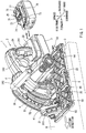
FIG. 1 is a perspective view of an example (not showing all features of the claims) of a cutting device in which a cutting device main body is placed at a top center position; -
FIG. 2 is a perspective view of the cutting device offigure 1 in which the cutting device main body is rotated downward from the top center position; -
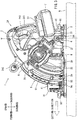
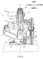
FIG. 3 is a side view of the cutting device offigure 1 in which the cutting device main body is placed at the top center position, as viewed from a left side in a cutting direction; -
FIG. 4 is a side view of the cutting device offigure 1 in which the cutting device main body is rotated downward from the top center position, as viewed from the left side in the cutting direction; -
FIG. 5 is a side view of a handle portion and a battery mounting portion (in a state where the battery is mounted) of the cutting device offigure 1 , as viewed from the rear side to the front side; -
FIG. 6 is a perspective view of a cutting device of an embodiment in which a cutting device main body is rotated downward from the top center portion; -
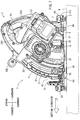
FIG. 7 is a side view of the cutting device of an embodiment in which the cutting device main body is placed at the top center portion, as viewed from the left side in the cutting direction; -
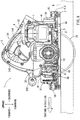
FIG. 8 is a side view of the cutting device of the embodiment in which the cutting device main body is rotated downward from the top center portion, as viewed from the left side in the cutting direction; -
FIG. 9 is a side view of the cutting device of an embodiment in which the cutting device main body is placed at the top center portion, as viewed from the rear side to the front side; and -
FIG. 10 is a side view of an embodiment of a cutting device in which the cutting device main body is rotated downward from the top center portion, as viewed from the rear side to the front side. - A cutting device according to an example will be described with reference to
FIG. 1 to FIG. 10 . - First, a
cutting device 1 of one example (not showing all features of the claims) will be described with reference toFIG. 1 to FIG. 5 . - In this explanation, the front side, the rear side, the left side, the right side, the upper side, and the lower side are shown. As shown in
FIG. 1 , based on abase 3, a side on which thebase 3 is brought into contact with a material W to be cut corresponds to the lower side. Converserly, a side on which a cutting machinemain body 2 is disposed corresponds to the upper side. Further, a side to which cutting of a cutting device advances (cutting direction) corresponds to the front side, and the side opposite the front side is the rear side. Also, the left side and the right side are determined as viewed from the rear side. - In a normal condition of the
cutting device 1, the cutting machinemain body 2, which includes acutting blade 25, is placed at a top center position at which a lower end part of thecutting blade 25 is above the base 3 (refer toFIG. 1 andFIG. 3 ). The top center position corresponds to an initial position. The cutting machinemain body 2 is moved from the initial position to a lower position at which the lower end part of thecutting blade 25 protrudes below thebase 3, and a processing operation of the material W to be cut can be performed by the cutting blade 25 (refer toFIG. 2 andFIG. 4 ). In general, this kind of acutting device 1 is called a plunge cut saw. - As shown in
FIG. 1 , thecutting device 1 of the example includes a flat rectangular plate shapedbase 3 that is brought into contact with the material W to be cut, ablade case 4 that covers at least a portion of thecutting blade 25 above thebase 3, and the cutting machinemain body 2 that is rotated with respect to theblade case 4. - The cutting machine
main body 2 includes anelectric motor 22 that is served as a drive source, abattery mounting portion 23 on which arechargeable battery 7 that serves as a power source can be mounted, thecircular cutting blade 25 that is rotated by theelectric motor 22, ahandle portion 24 that is held by a user, and asupport arm 21 that supports both thehandle portion 24 and theelectric motor 22. Further, thesupport arm 21 is rotatably supported by theblade case 4 via arotating shaft 6. - A cutting depth adjustment mechanism 5 (depth guide) that is used to adjust a cutting depth of the
cutting blade 25 is provided on the front left side of theblade case 4. In the cuttingdepth adjustment mechanism 5, astopper 52, which is positioned along a long arcuate-shapedhole 51 provided in theblade case 4, is provided so as to protrude from theblade case 4 with respect to thelong hole 51. Thestopper 52 can be fixed at an appropriate position along thelong hole 51. Further, thestopper 52 is configured to engage an engagingprotrusion 26 that protrudes from the cutting machinemain body 2. Accordingly, a bottom center position, which is obtained when the cutting machinemain body 2 is rotated upward, can be adjusted by changing a fixed position of thestopper 52. In this way, the cuttingdepth adjustment mechanism 5 can adjust a length of thecutting blade 25 that protrudes from thebase 3, that is, the cutting depth. Thus, the material W to be cut can be easily cut while a desired cutting depth is maintained. - Meanwhile, a user can rotate the cutting machine
main body 2 from the top center position to the bottom center position. - In the example, the cutting
depth adjustment mechanism 5 is provided on the left surface of theblade case 4 at the front side of a rotating shaft (not shown) of thecutting blade 25. Thebattery mounting portion 23 is provided at one end side of thehandle portion 24 that is positioned at the rear side of the rotating shaft of thecutting blade 25. In this way, the cuttingdepth adjustment mechanism 5 is positioned in front of thebattery 7, and as a whole, a compact configuration in a width direction can be achieved. As thebattery 7 can be disposed adjacent to theblade case 4, compactness in a right-left direction can be obtained. - In addition, according to this configuration, a surface BC corresponding to the center in the right-left direction of the
battery 7 can substantially coincide with a surface HC corresponding to the center in the right-left direction of a main handle 241 (refer toFIG. 5 ). In other words, themain handle 241 and thebattery mounting portion 23 that are integrated with themain handle 241 can be formed to be approximately bilaterally symmetrical. Accordingly, the left and right balance in terms of weight of thebattery 7 can be prevented from biasing towards one side, while compactness of thecutting device 1 is maintained. Unlike the present example, if the cuttingdepth adjustment mechanism 5 shown inFIG. 1 is forced to a position to the rear of the rotating shaft of thecutting blade 25 and the cuttingdepth adjustment mechanism 5 and thebattery 7 are disposed adjacent to each other the right-left direction, problems may occur. Themain handle 241 is forced to further protrude to the left side than inFIG. 1 , and thus, it is difficult to make theentire cutting device 1 to be compact. In contrast, the example of the present teachings can avoid the above-described problem. - The
handle portion 24 in the cutting machinemain body 2 includes themain handle 241 which is usually held by a user. The inside of themain handle 241 typically includes anoperation member 243. Thehandle portion 24 also includes afront grip 242 that extends in the right-left direction from themain handle 241. - The
operation member 243 is a trigger that can be pulled. By pulling the trigger, theelectric motor 22 is activated and thecutting blade 25 rotates. - The
main handle 241 is formed in an approximately U shape, and thebattery mounting portion 23 is disposed on one end side of themain handle 241. Also, theelectric motor 22 is disposed on the other end side of themain handle 241. Since theelectric motor 22 and thebattery 7, which are relatively heavy, are disposed on both ends of themain handle 241, the balance with respect to the weight in the front and rear of themain handle 241 can be maintained. Thus, a sense of balance when themain handle 241 is held can be improved. - Also, the
front grip 242 is positioned extending in a longitudinal direction from thesupport arm 21. Accordingly, a force that rotates the cutting machinemain body 2 can be easily transmitted. - Further, in the
cutting device 1 of the example, in order to adjust the cutting depth, the cutting machinemain body 2 and theblade case 4 are connected to each other via therotating shaft 6 that is provided to be approximately perpendicular to a plane of theblade case 4. - In the cutting machine
main body 2, thesupport arm 21 has an approximately fan-shaped configuration in a side view when viewed from the direction shown inFIG. 3 . The side of the narrowed width part is connected to theblade case 4. In thesupport arm 21, theelectric motor 22 and thehandle portion 24 are connected to the opposite side in the longitudinal direction with regard to the side connected to therotating shaft 6. Also, a part from thesupport arm 21 to thebattery mounting portion 23 has an approximately U-shaped configuration in a side view, as shown inFIG. 3 . This configuration enables the end of the mountedbattery 7 to be positioned close to therotating shaft 6. By adopting this configuration, the coupling form of thesupport arm 21, thehandle portion 24, and thebattery 7 has an approximately fan-shaped configuration in a side view, as shown inFIG. 3 . - According to this configuration, relatively heavy loads such as the
electric motor 22 and thebattery 7 can be positioned adjacent therotating shaft 6. Thus, when rotating the cutting machinemain body 2, a user does not need to apply an excessive force to thecutting device 1, which is easy to handle for the user. Further, according to the configuration, electric wiring can be efficiently performed inside a case of thehandle portion 24, and wiring paths can be efficiently and easily obtained. - The
battery mounting portion 23 is configured to rotate integrally with theelectric motor 22 with respect to a turning fulcrum at which therotating shaft 6 is formed. Accordingly, bending of electric wires connecting thebattery mounting portion 23 and theelectric motor 22 is not performed repeatedly, and thus disconnection due to the bending can be prevented. In contrast, unlike the present example, in a case where thebattery mounting portion 23 and theelectric motor 22 rotate independently with each other, at least a part of the electric wires connected between thebattery mounting portion 23 and theelectric motor 22 has to be configured to be bendable enough not to cause disconnection. However, due to repeated bending, there is a high possibility that disconnection may occur. According to the configuration of the example of the present teachings, since bending of the electric wires are not performed repeatedly, it is ensured that disconnection does not occur. - In addition, as shown in
FIG. 3 , thebattery mounting portion 23 and theelectric motor 22 are disposed on opposite sides in a front-rear direction with respect to the rotating shaft 6 (the turning fulcrum). That is, theelectric motor 22 is positioned at the front side on the basis of a dashed line V shown inFIG. 3 , and thebattery mounting portion 23 is positioned at the rear side. Due to the positional relationship, theelectric motor 22 having a relatively heavy load is disposed at the front side with respect to the rotating shaft 6 (the turning fulcrum), and thebattery 7 having a relatively heavy load is disposed at the rear side with respect to the rotating shaft 6 (the turning fulcrum). Accordingly, compared to a case where theelectric motor 22 and thebattery 7 are mounted on either the front side or the rear side with respect to the rotating shaft 6 (the turning fulcrum), a force that is applied to rotate can be preventing from being biased to either the front side or the rear side. Therefore, even when the cutting device is rotated to either the front side or the rear side, a user's burden in operating the cutting device can be suppressed. It is ideal that the condition that thebattery mounting portion 23 and theelectric motor 22 have the relationship positioned on opposite sides in the front-rear direction with respect to therotating shaft 6 is always satisfied. It is preferred even when the cutting machinemain body 2 is rotated in any direction. However, it is not necessary to satisfy this condition. In the present specification, the description that thebattery mounting portion 23 and theelectric motor 22 can be disposed on opposite sides in the front-rear direction with respect to the turning fulcrum means that any configuration is available if thebattery mounting portion 23 and theelectric motor 22 are disposed on opposite sides in the front-rear direction with respect to the turning fulcrum. - Further, according to the invention, a compression spring that is an
elastic member 8 is disposed below theelectric motor 22, and theelectric motor 22 can be biased upward. According to this configuration, the cutting machinemain body 2 can be rotated downward from the position of the initial state. When an operation force for rotating the cutting machine main body is released, the cutting machine main body can be automatically restored to the initial state. Alternatively, the force required for restoring to the initial state can be decreased. - Further, in the
cutting device 1 of the example, theblade case 4 is positioned at one end in the right-left direction. Though not shown, thecutting blade 25 protrudes below thebase 3 along the vicinity of the right end of thebase 3. Accordingly, even when a floor surface is cut, a cutting operation in the vicinity of a wall (a so-called edge cutting) can be performed. Further, since theblade case 4 is formed on one end in the right-left direction, the width in the right-left direction can be narrowed, as compared to the situation where thebase 3 is formed on one end in the right-left direction. - Further, when the cutting machine
main body 2 is placed at the top center position, theentire cutting blade 25 is positioned above thebase 3. Further, by rotation of the cutting machinemain body 2, thecutting blade 25 protrudes downward from thebase 3. Thus, the cutting operation with respect to the material W to be cut can be easily and conveniently performed. - The
battery 7 of the example is a lithium ion battery of 18 V, and a plurality of battery cells are housed in a case of thebattery 7. Thebattery 7 can be removed from thecutting device 1, and can be charged by a charger that is separately prepared. Thus, thebattery 7 can be repeatedly used as a power source. Thebattery 7 includes a pair of right and leftrail portions negative connection terminals terminal grooves rail portions connector 75 for transmitting and receiving a control signal is provided between the positive andnegative connection terminals - Further, on an end of the upper surface of the
battery 7 in the removal direction, alock claw 76 for locking thebattery 7 with respect to thebattery mounting portion 23 is provided. It can be moved vertically. - The
battery mounting portion 23 of the example is provided to form a surface approximately perpendicular to the longitudinal direction of a grip portion of themain handle 241 and at the lower end of themain handle 241. Thebattery 7 can be mounted and removed by sliding it in the front-rear direction as shown inFIG. 1 . According to this configuration, a user can easily mount thebattery 7 with one hand, while lightly holding themain handle 241 with another hand. This is because the user can firmly hold themain handle 241 in order to slidably mount thebattery 7 to thebattery mounting portion 23. - The
battery 7 can be easily mounted from the direction approximately perpendicular to the longitudinal direction of the grip portion of themain handle 241. - Due to the fact that the
battery mounting portion 23 is provided on the lower end of themain handle 241 and thebattery 7 can be mounted with the right and left hands positioned close together. In this way, thebattery 7 can be easily mounted to thebattery mounting portion 23. - Further, as shown in
FIG. 5 , a center in the right-left direction of themain handle 241 approximately coincides with a center in the right-left direction of thebattery mounting portion 23. Thus, the mounting of thebattery 7 to thebattery mounting portion 23 can be easily performed. This is because at the time of the mounting, one hand with which themain handle 241 is supported can be positioned 7 in the up-down direction in parallel with another hand with which thebattery 7 is mounted. - With respect to the
cutting device 1 of the example, matters other than the above-described matters will be described below. - The
cutting device 1 includes an inclination mechanism that can set the cutting machinemain body 2 and theblade case 4 at an incline with respect to thebase 3. Accordingly, in thecutting device 1 of the example having the inclination mechanism, by raising the cutting machinemain body 2 connected to theblade case 4 to the right side, theblade case 4 can be set at an incline with respect to thebase 3. As shown inFIG. 2 , in the inclination mechanism, oblique-cuttingsupport plates base 3. In addition, oblique-cuttingpieces blade case 4. The oblique-cuttingsupport plates pieces blade case 4 and the cutting machinemain body 2 can be raised to the inner side of the drawing. More specifically, this refers to the right side inFIG. 1 . Theblade case 4 and the cutting machinemain body 2 can be largely raised to the right side, but they may be slightly raised to the front side of the drawing. More specifically, this refers to the left side inFIG. 1 . - An approximately arc-shaped
hole 312 that is used for limiting an inclination range of theblade case 4 is provided in the oblique-cuttingsupport plate 31. Further, a protrusion (not shown) that is fitted to and protrudes from thehole 312 is provided in the oblique-cuttingpiece 41. Anoperation portion 412, which can rotate around the protrusion, can be mounted on the tip of the protrusion (refer toFIG. 6 to FIG. 10 ). When theoperation portion 412 is rotated clockwise around the protrusion, the oblique-cuttingsupport plate 31 and the oblique-cuttingpiece 41 can be closely fitted to each other, and thus, they are forced to be relatively immovable to each other. Accordingly, theblade case 4 etc. is forced to be relatively immovable with respect to thebase 3. By contrast, when theoperation portion 412 is rotated counterclockwise, the fitting condition between the oblique-cuttingsupport plate 31 and the oblique-cuttingpiece 41 is loosened, and they can be moved relatively to each other. Accordingly, theblade case 4 etc. can be moved with respect to thebase 3. - Further, the
cutting device 1 of the example includes a positive locking mechanism by which a highly-used inclination angle such as 22.5°, 45°, etc. can be set. Since this positive locking mechanism is well-known, detailed explanations are omitted. - Further, the
cutting device 1 of the example can be configured to be placed on a rail member (not shown) such that thebase 3 of thecutting device 1 can be slidably moved on the rail member. - Next, a second example will be described with reference to
FIG. 6 to FIG. 10 . - Similar to the first example, the cutting
depth adjustment mechanism 5 is disposed at the front side of thecutting device 1 and thebattery mounting portion 23 is disposed at the rear side in the second example (refer toFIG. 6 ). Also, similar to the first example, the cutting machinemain body 2 can be rotated about therotating shaft 6 that serves as the turning fulcrum. In some embodiments, thecutting blade 25 does not protrude below the base 3 (refer toFIG. 7 andFIG. 9 ), while in others, thecutting blade 25 protrudes below the base 3 (refer toFIG. 8 andFIG. 10 ). These embodiments can be selected in the second embodiment. Further, the cuttingdepth adjustment mechanism 5 is provided such that the cutting depth of the material W to be cut can be easily set to a specific depth. Main differences between the first example and the second example relate to a positional relationship between thehandle portion 24 and thebattery mounting portion 23. The differences will be described below. - In the second example, the
battery mounting portion 23 is formed an at incline with respect to the surface HC in the right-left direction of amain handle 241. Further, thebattery mounting portion 23 is formed at an incline such that an opposite side (left side) of thebattery mounting portion 23 with respect to theblade case 4 is relatively positioned above a side facing the blade case 4 (right side). More specifically, when the circular-shapedcutting blade 25 is positioned orthogonal to the base 3 (that is, when the rotating shaft (not shown) of thecutting blade 25 is positioned to be parallel to the base 3), the left end side of thebattery mounting portion 23 is inclined to be relatively positioned above the right end side. Thebattery 7 is mounted on the lower side of thebattery mounting portion 23, and thebattery 7 has an approximately rectangular parallelepiped shape. Thus, thebattery 7 is disposed such that a left side of a bottom part of thebattery 7 is positioned above a right side of the bottom part of the battery 7 (refer toFIG. 9 andFIG. 10 ). - In addition, the cutting machine
main body 2 rotates about therotating shaft 6 and can be inclined in the right-left direction. Accordingly, the positional relationship between the cutting machinemain body 2 and thebase 3 can be changed. A gap exists between the battery mounting portion 24 (or the battery 7) and thebase 3. When the circular-shapedcutting blade 25 is positioned orthogonal to thebase 3 the gap of the side opposite the blade case 4 (left side) is relatively larger than that of the gap on the side facing the blade case 4 (right side). Meanwhile, a user uses thecutting device 1 very often in which the circular-shapedcutting blade 25 is positioned orthogonal to thebase 3. Therefore, according to the second example, the user can easily insert a hand below thebattery mounting portion 23 or thebattery 7 from the side opposite theblade case 4. - There are disposed various operating members operated by the user such as a fixing
screw 93 that is used to fix the upper surface of thebase 3 to a rail member (not shown), anadjustment screw 94 that can adjust the backlash between the upper surface and the rail member (not shown), or aslide lever 95 that can prevent thecutting device 1 from being derailed from the rail member (not shown). Even when the operating members are disposed immediately below thebattery 7 or thebattery mounting portion 23, the user can relatively easily operate these operating members. - Further, in the second example, the
battery 7 is displaced to theblade case 4 side (right side) such that thebattery 7 can be mounted to the battery mounting portion 23 (refer toFIG. 10 ). The mounting surface positioned below thebattery mounting portion 23 can be easily viewed, and thus, the mounting of thebattery 7 can be easily performed. Also, thebattery 7 is displaced to the side (left side) opposite to theblade case 4 in order to remove thebattery 7 from thebattery mounting portion 23. - The
battery mounting portion 23 is described in detail below. When thecutting blade 25 is positioned orthogonal to thebase 3, the left end side of thebattery mounting portion 23 is inclined to be positioned above the right end side. Referring toFIG. 10 , an angle θ between the mounting surface of the battery mounting portion 23 (inclination surface AI along the battery 7) and the surface HC (vertical line relative to the bottom surface of the base 3) is formed to be more than 0° and less than 90°. InFIG. 10 , the angle θ is formed to be 60°. It is preferable that the angle θ be selected from a range from 5° to 85° such as 45°, 55°, or 60°. When thecutting blade 25 is positioned orthogonal to thebase 3 and the height of the mounting surface of thebattery mounting portion 23 is approximately the same in the front-rear direction (refer toFIG. 10 ), it is preferable that the opposite side (left side) of thebattery mounting portion 23 with regard to theblade case 4 is positioned above the side (right side) facing theblade case 4 side. - In the present example, the attaching and detaching directions of the battery can be adjusted by use of the inclination mechanism. This will be briefly described below.
- First, by rotating the
operation portion 412, theblade case 4 and the cutting machinemain body 2 are maintained such that they may be set at an incline with regard to thebase 3. When the angle θ between the mounting surface of thebattery mounting portion 23 and the surface HC is 60°, moving the top part of theblade case 4 in a direction shown by a white arrow inFIG. 10 and setting the cutting machinemain body 2 at an incline angle of 60°, the mounting and removal directions of thebattery 7 can be set orthogonal to thebase 3. When the angle θ is 45°, by setting the cutting machinemain body 2 at an incline angle of 45°, the mounting and removal directions of thebattery 7 can be orthogonal to thebase 3. In this way, the mounting or the removal of the battery can be easily performed. In addition, when the angle θ is approximately the same as the angle of the positive lock, the user can more easily use thecutting device 1. - Further, the angle between the mounting direction or the removal direction of the
battery 7 and the direction orthogonal to thebase 3 may have an angle of less than 45°. When the angle is 45°, 15°, or the like, thebattery 7 can be mounted on thebattery mounting portion 23 in a state where the battery is slightly inclined with respect to the direction orthogonal to thebase 3. - Further, the maximum angle by which the cutting machine
main body 2 is inclined by the inclination mechanism can be determined according to the kind ofcutting device 1, and the maximum angle may be 45°, 55°, 60°, or the like. When the cutting machinemain body 2 is set at an incline having the maximum angle, it is preferable that the angle between the mounting direction or the removal direction of thebattery 7 and the direction orthogonal to thebase 3 be set to have an angle of 45° or less. Further, when the cutting machinemain body 2 is raised by the angle of the positive lock, it is preferable that the angle between the mounting direction or the removal direction of thebattery 7 and the direction orthogonal to thebase 3 be set to have an angle of 45° or less. - Further, though not shown in the figures, the
battery 7 may intersect the surface HC corresponding to the centerline in the right-left direction of themain handle 241. In this case, thebattery mounting portion 23 or thebattery 7 may be positioned to protrude at both right and left sides from both the right and left end parts of themain handle 241. As the typical example, the surface HC corresponding to the center in the right-left direction of themain handle 241 may approximately coincide with the center in the right-left direction of the battery mounting surface. Thebattery mounting portion 23 may be provided on one end of themain handle 241. - The two examples are described above, but the present teachings may include various modifications in addition to the above-described examples.
- For example, the battery is not limited to 18 V output, and may include various outputs such as 10.8 V, 14.4 V, or 36 V.
- Further, a plurality of batteries may be used together.
- Further, in the above examples, the battery is slidably mounted to the battery mounting portion. However, the battery may be attached to the battery mounting portion by engaging the former with the latter in an up-down direction.
- Further, the battery is not limited to the battery having an approximately rectangular parallelepiped shape, and may include a battery having a cylindrical shape, a square-pole shape, or the like.
Claims (8)
- A cutting device (1) having a base (3) that is brought into contact with a material (W) to be cut and also having a cutting machine main body (2) that is positioned above an upper surface of the base (3),
wherein the cutting machine main body (2) has an electric motor (22) that serves as a drive source, a battery mounting portion (23) to which a rechargeable battery (7) that serves as a power source is mounted, a circular cutting blade (25) that is adapted to be rotated by the electric motor (22), and a handle portion (24) that is held by a user,
wherein the cutting machine main body (2) can be rotated from a top center position to a bottom center position,
wherein a cutting depth adjustment mechanism (5) that is used to adjust a cutting depth of the cutting blade (25) is located in front of the battery mounting portion (23),
characterized in that
an elastic member (8) that can bias the electric motor (22) in an upward direction is located below the electric motor (22), and
the entire battery (7) is located generally forward a rear end of the base (3) in plan view when the cutting machine main body is rotated from the top center positon to the bottom center position. - The cutting device (1) according to claim 1,
wherein the battery mounting portion (23) is located on one end of the handle portion (24) and the electric motor (22) is located on an opposite end of the handle portion (24). - The cutting device (1) according to claim 1 or 2,
wherein the electric motor (22) is adapted to be rotated integrally with the battery mounting portion (23) around a turning fulcrum (6); and
the electric motor (22) is located in front of the turning fulcrum (6) and the battery mounting portion (23) is located behind the turning fulcrum (6). - The cutting device (1) according to any one of claims 1 to 3,
wherein when the cutting blade (25) is positioned orthogonal to the base (3), the battery (7) is positioned at an incline such that an opposite side of the battery mounting portion (23) with respect to the cutter blade (25) is positioned above a cutter blade side of the battery mounting portion (23) facing the cutter blade (25). - The cutting device (1) according to claim 4,
wherein the battery (7) is mounted to the battery mounting portion (23) by sliding the battery (7) along the battery mounting portion (23) from the side opposite the cutter blade (25) towards the cutter blade side. - The cutting device (1) according to claim 4 or 5, wherein the battery (7) is mounted to the battery mounting portion (23) in a direction orthogonal to the cutting direction of the material (W) to be cut when viewed from above.
- The cutting device (1) according to any one of claims 1 to 6, further comprising:an inclination mechanism (31, 41) that can set the cutting machine main body (2) at an incline such that the cutting blade (25) is inclined with respect to the base (3) in a right and left direction, characterized in thatan angle between a mounting direction or a removal direction of the battery (7) and a direction orthogonal to the base (3) can be set to be 45° or less by setting the cutting machine main body (2) at an incline with respect to the base (3).
- The cutting device (1) according to claim 7, wherein a maximum inclination angle that can be set by the inclination mechanism (31, 41) is 45°, 55°, or 60°.
Applications Claiming Priority (2)
| Application Number | Priority Date | Filing Date | Title |
|---|---|---|---|
| JP2013015514 | 2013-01-30 | ||
| JP2013258991A JP2014166745A (en) | 2013-01-30 | 2013-12-16 | Rechargeable cutting tool |
Publications (2)
| Publication Number | Publication Date |
|---|---|
| EP2762282A1 EP2762282A1 (en) | 2014-08-06 |
| EP2762282B1 true EP2762282B1 (en) | 2018-03-21 |
Family
ID=49998181
Family Applications (1)
| Application Number | Title | Priority Date | Filing Date |
|---|---|---|---|
| EP14152708.5A Revoked EP2762282B1 (en) | 2013-01-30 | 2014-01-27 | Cutting devices |
Country Status (2)
| Country | Link |
|---|---|
| EP (1) | EP2762282B1 (en) |
| JP (1) | JP2014166745A (en) |
Families Citing this family (4)
| Publication number | Priority date | Publication date | Assignee | Title |
|---|---|---|---|---|
| JP6926440B2 (en) * | 2016-10-20 | 2021-08-25 | マックス株式会社 | Portable cutting machine |
| JP6847648B2 (en) * | 2016-12-05 | 2021-03-24 | 株式会社マキタ | Cutting machine |
| JP7208031B2 (en) | 2019-01-24 | 2023-01-18 | 株式会社マキタ | portable cutting machine |
| USD951051S1 (en) | 2020-01-02 | 2022-05-10 | Techtronic Cordless Gp | Circular saw |
Citations (19)
| Publication number | Priority date | Publication date | Assignee | Title |
|---|---|---|---|---|
| DE3318507A1 (en) | 1982-06-21 | 1983-12-22 | Matsushita Electric Works, Ltd., Kadoma, Osaka | PORTABLE ELECTRIC CIRCULAR SAW |
| JPS59140001A (en) | 1983-01-31 | 1984-08-11 | 松下電工株式会社 | Battery type circular saw |
| JPS6021201A (en) | 1983-07-15 | 1985-02-02 | 松下電工株式会社 | Circular saw |
| JPS63198501U (en) | 1987-06-15 | 1988-12-21 | ||
| US4847513A (en) | 1988-02-26 | 1989-07-11 | Black & Decker Inc. | Power-operated device with a cooling facility |
| DE10141454A1 (en) | 2001-08-23 | 2003-03-13 | Hilti Ag | Battery powered circular saw |
| US20040045176A1 (en) | 2001-11-30 | 2004-03-11 | Oliver Koukal | Battery-powered manual machine tool |
| US20040049926A1 (en) | 2002-09-17 | 2004-03-18 | S-B Power Tool Corporation. | Cordless circular saw |
| GB2397797A (en) | 2003-01-29 | 2004-08-04 | Bosch Gmbh Robert | Hand tool machine |
| US20050217124A1 (en) | 2002-12-30 | 2005-10-06 | Wolfgang Fuchs | Hand-held circular saw |
| WO2005118195A2 (en) * | 2004-05-28 | 2005-12-15 | Scientific Molding Corporation Ltd. | Hand-held circular saw, in particular plunge-cut saw |
| DE102006034136A1 (en) | 2005-07-26 | 2007-04-05 | Makita Corp., Anjo | Portable circular saw |
| JP2008018498A (en) | 2006-07-13 | 2008-01-31 | Makita Corp | Cutter |
| USD572990S1 (en) | 2007-05-02 | 2008-07-15 | Black & Decker Inc. | Circular saw |
| EP2018920A1 (en) | 2007-07-26 | 2009-01-28 | Black & Decker, Inc. | Anti-kickback device |
| EP2045055A2 (en) | 2007-10-04 | 2009-04-08 | Black & Decker, Inc. | A power tool |
| US20090193949A1 (en) | 2008-02-05 | 2009-08-06 | Makita Corporation | Tool units for cutting devices |
| EP2486998A2 (en) | 2011-02-09 | 2012-08-15 | Makita Corporation | Cutting tools |
| EP2583776A1 (en) | 2011-10-20 | 2013-04-24 | Makita Corporation | Hand-held cutting tools |
Family Cites Families (1)
| Publication number | Priority date | Publication date | Assignee | Title |
|---|---|---|---|---|
| JP6006990B2 (en) | 2011-06-10 | 2016-10-12 | 日立Geニュークリア・エナジー株式会社 | Eddy current testing probe |
-
2013
- 2013-12-16 JP JP2013258991A patent/JP2014166745A/en active Pending
-
2014
- 2014-01-27 EP EP14152708.5A patent/EP2762282B1/en not_active Revoked
Patent Citations (19)
| Publication number | Priority date | Publication date | Assignee | Title |
|---|---|---|---|---|
| DE3318507A1 (en) | 1982-06-21 | 1983-12-22 | Matsushita Electric Works, Ltd., Kadoma, Osaka | PORTABLE ELECTRIC CIRCULAR SAW |
| JPS59140001A (en) | 1983-01-31 | 1984-08-11 | 松下電工株式会社 | Battery type circular saw |
| JPS6021201A (en) | 1983-07-15 | 1985-02-02 | 松下電工株式会社 | Circular saw |
| JPS63198501U (en) | 1987-06-15 | 1988-12-21 | ||
| US4847513A (en) | 1988-02-26 | 1989-07-11 | Black & Decker Inc. | Power-operated device with a cooling facility |
| DE10141454A1 (en) | 2001-08-23 | 2003-03-13 | Hilti Ag | Battery powered circular saw |
| US20040045176A1 (en) | 2001-11-30 | 2004-03-11 | Oliver Koukal | Battery-powered manual machine tool |
| US20040049926A1 (en) | 2002-09-17 | 2004-03-18 | S-B Power Tool Corporation. | Cordless circular saw |
| US20050217124A1 (en) | 2002-12-30 | 2005-10-06 | Wolfgang Fuchs | Hand-held circular saw |
| GB2397797A (en) | 2003-01-29 | 2004-08-04 | Bosch Gmbh Robert | Hand tool machine |
| WO2005118195A2 (en) * | 2004-05-28 | 2005-12-15 | Scientific Molding Corporation Ltd. | Hand-held circular saw, in particular plunge-cut saw |
| DE102006034136A1 (en) | 2005-07-26 | 2007-04-05 | Makita Corp., Anjo | Portable circular saw |
| JP2008018498A (en) | 2006-07-13 | 2008-01-31 | Makita Corp | Cutter |
| USD572990S1 (en) | 2007-05-02 | 2008-07-15 | Black & Decker Inc. | Circular saw |
| EP2018920A1 (en) | 2007-07-26 | 2009-01-28 | Black & Decker, Inc. | Anti-kickback device |
| EP2045055A2 (en) | 2007-10-04 | 2009-04-08 | Black & Decker, Inc. | A power tool |
| US20090193949A1 (en) | 2008-02-05 | 2009-08-06 | Makita Corporation | Tool units for cutting devices |
| EP2486998A2 (en) | 2011-02-09 | 2012-08-15 | Makita Corporation | Cutting tools |
| EP2583776A1 (en) | 2011-10-20 | 2013-04-24 | Makita Corporation | Hand-held cutting tools |
Non-Patent Citations (5)
| Title |
|---|
| ANONYMOUS: "DC 351. Heavy-Duty 28V Cordless Track Saw", DEWALT - INSTRUCTION MANUAL, August 2008 (2008-08-01), XP055538695 |
| ANONYMOUS: "DeWalt Tauchkreissägen DWS 520 K und DC 351 KL", WERKZEUG-NEWS, 1 May 2008 (2008-05-01), XP055538706, Retrieved from the Internet <URL:https://www.werkzeug-news.de/elektrowerkzeuge/08/dewalt-tauchkreissaegen.html> |
| ANONYMOUS: "DWS 520 K / DC 351", DEWALT - PROSPEKT, 2008, XP055538710 |
| ANONYMOUS: "DWS 520", DEWALT - HANDBUCH, XP055538701 |
| ANONYMOUS: "Innovationbörse am 28. und 29. November 2007", DEWALT - PROSPEKT, 28 November 2007 (2007-11-28), pages 1 - 24, XP055538698 |
Also Published As
| Publication number | Publication date |
|---|---|
| EP2762282A1 (en) | 2014-08-06 |
| JP2014166745A (en) | 2014-09-11 |
Similar Documents
| Publication | Publication Date | Title |
|---|---|---|
| US10583504B2 (en) | Tabletop cutting device | |
| US20160176064A1 (en) | Cutting device | |
| EP2762282B1 (en) | Cutting devices | |
| EP2189251B1 (en) | Battery packs | |
| US9263715B2 (en) | Battery pack, electric tool and battery charger | |
| EP2596918B1 (en) | Electric tools | |
| US20100299943A1 (en) | Circular saw having a direct current power supply | |
| US20160294093A1 (en) | Electric apparatus | |
| CN108687872B (en) | Portable processing machine | |
| CN110653417B (en) | Portable band saw | |
| EP2873479A1 (en) | Portable cutting tool | |
| EP2591887B1 (en) | Electric power tool | |
| JP6084474B2 (en) | Rechargeable cutting tool | |
| EP3216573B1 (en) | Power tool with toolless blade release mechanism | |
| CN108698220B (en) | Battery-operated hand-held power tool | |
| JP2017019025A (en) | Extension handle for rechargeable hand-held electric power tool | |
| JP6615851B2 (en) | Tabletop cutting machine | |
| JP2017013184A (en) | Hand-held rechargeable power tool | |
| JP6317001B2 (en) | Tabletop cutting machine | |
| US20240128576A1 (en) | Lock for a rechargeable battery | |
| US20230249268A1 (en) | Portable cutting machine | |
| JP2021014122A (en) | Stationary type processing machine for woodwork | |
| JP6370935B2 (en) | Rechargeable cutting tool | |
| JP2020192782A (en) | Portable cutting machine |
Legal Events
| Date | Code | Title | Description |
|---|---|---|---|
| PUAI | Public reference made under article 153(3) epc to a published international application that has entered the european phase |
Free format text: ORIGINAL CODE: 0009012 |
|
| 17P | Request for examination filed |
Effective date: 20140127 |
|
| AK | Designated contracting states |
Kind code of ref document: A1 Designated state(s): AL AT BE BG CH CY CZ DE DK EE ES FI FR GB GR HR HU IE IS IT LI LT LU LV MC MK MT NL NO PL PT RO RS SE SI SK SM TR |
|
| AX | Request for extension of the european patent |
Extension state: BA ME |
|
| R17P | Request for examination filed (corrected) |
Effective date: 20150115 |
|
| RBV | Designated contracting states (corrected) |
Designated state(s): AL AT BE BG CH CY CZ DE DK EE ES FI FR GB GR HR HU IE IS IT LI LT LU LV MC MK MT NL NO PL PT RO RS SE SI SK SM TR |
|
| STAA | Information on the status of an ep patent application or granted ep patent |
Free format text: STATUS: EXAMINATION IS IN PROGRESS |
|
| 17Q | First examination report despatched |
Effective date: 20170206 |
|
| GRAP | Despatch of communication of intention to grant a patent |
Free format text: ORIGINAL CODE: EPIDOSNIGR1 |
|
| STAA | Information on the status of an ep patent application or granted ep patent |
Free format text: STATUS: GRANT OF PATENT IS INTENDED |
|
| INTG | Intention to grant announced |
Effective date: 20171020 |
|
| GRAS | Grant fee paid |
Free format text: ORIGINAL CODE: EPIDOSNIGR3 |
|
| GRAA | (expected) grant |
Free format text: ORIGINAL CODE: 0009210 |
|
| STAA | Information on the status of an ep patent application or granted ep patent |
Free format text: STATUS: THE PATENT HAS BEEN GRANTED |
|
| AK | Designated contracting states |
Kind code of ref document: B1 Designated state(s): AL AT BE BG CH CY CZ DE DK EE ES FI FR GB GR HR HU IE IS IT LI LT LU LV MC MK MT NL NO PL PT RO RS SE SI SK SM TR |
|
| REG | Reference to a national code |
Ref country code: GB Ref legal event code: FG4D |
|
| REG | Reference to a national code |
Ref country code: CH Ref legal event code: EP |
|
| REG | Reference to a national code |
Ref country code: AT Ref legal event code: REF Ref document number: 980602 Country of ref document: AT Kind code of ref document: T Effective date: 20180415 |
|
| REG | Reference to a national code |
Ref country code: IE Ref legal event code: FG4D |
|
| REG | Reference to a national code |
Ref country code: DE Ref legal event code: R096 Ref document number: 602014022486 Country of ref document: DE |
|
| REG | Reference to a national code |
Ref country code: NL Ref legal event code: MP Effective date: 20180321 |
|
| PG25 | Lapsed in a contracting state [announced via postgrant information from national office to epo] |
Ref country code: NO Free format text: LAPSE BECAUSE OF FAILURE TO SUBMIT A TRANSLATION OF THE DESCRIPTION OR TO PAY THE FEE WITHIN THE PRESCRIBED TIME-LIMIT Effective date: 20180621 Ref country code: FI Free format text: LAPSE BECAUSE OF FAILURE TO SUBMIT A TRANSLATION OF THE DESCRIPTION OR TO PAY THE FEE WITHIN THE PRESCRIBED TIME-LIMIT Effective date: 20180321 Ref country code: LT Free format text: LAPSE BECAUSE OF FAILURE TO SUBMIT A TRANSLATION OF THE DESCRIPTION OR TO PAY THE FEE WITHIN THE PRESCRIBED TIME-LIMIT Effective date: 20180321 Ref country code: CY Free format text: LAPSE BECAUSE OF FAILURE TO SUBMIT A TRANSLATION OF THE DESCRIPTION OR TO PAY THE FEE WITHIN THE PRESCRIBED TIME-LIMIT Effective date: 20180321 Ref country code: HR Free format text: LAPSE BECAUSE OF FAILURE TO SUBMIT A TRANSLATION OF THE DESCRIPTION OR TO PAY THE FEE WITHIN THE PRESCRIBED TIME-LIMIT Effective date: 20180321 |
|
| REG | Reference to a national code |
Ref country code: LT Ref legal event code: MG4D |
|
| REG | Reference to a national code |
Ref country code: AT Ref legal event code: MK05 Ref document number: 980602 Country of ref document: AT Kind code of ref document: T Effective date: 20180321 |
|
| PG25 | Lapsed in a contracting state [announced via postgrant information from national office to epo] |
Ref country code: RS Free format text: LAPSE BECAUSE OF FAILURE TO SUBMIT A TRANSLATION OF THE DESCRIPTION OR TO PAY THE FEE WITHIN THE PRESCRIBED TIME-LIMIT Effective date: 20180321 Ref country code: BG Free format text: LAPSE BECAUSE OF FAILURE TO SUBMIT A TRANSLATION OF THE DESCRIPTION OR TO PAY THE FEE WITHIN THE PRESCRIBED TIME-LIMIT Effective date: 20180621 Ref country code: SE Free format text: LAPSE BECAUSE OF FAILURE TO SUBMIT A TRANSLATION OF THE DESCRIPTION OR TO PAY THE FEE WITHIN THE PRESCRIBED TIME-LIMIT Effective date: 20180321 Ref country code: LV Free format text: LAPSE BECAUSE OF FAILURE TO SUBMIT A TRANSLATION OF THE DESCRIPTION OR TO PAY THE FEE WITHIN THE PRESCRIBED TIME-LIMIT Effective date: 20180321 Ref country code: GR Free format text: LAPSE BECAUSE OF FAILURE TO SUBMIT A TRANSLATION OF THE DESCRIPTION OR TO PAY THE FEE WITHIN THE PRESCRIBED TIME-LIMIT Effective date: 20180622 |
|
| PG25 | Lapsed in a contracting state [announced via postgrant information from national office to epo] |
Ref country code: EE Free format text: LAPSE BECAUSE OF FAILURE TO SUBMIT A TRANSLATION OF THE DESCRIPTION OR TO PAY THE FEE WITHIN THE PRESCRIBED TIME-LIMIT Effective date: 20180321 Ref country code: PL Free format text: LAPSE BECAUSE OF FAILURE TO SUBMIT A TRANSLATION OF THE DESCRIPTION OR TO PAY THE FEE WITHIN THE PRESCRIBED TIME-LIMIT Effective date: 20180321 Ref country code: NL Free format text: LAPSE BECAUSE OF FAILURE TO SUBMIT A TRANSLATION OF THE DESCRIPTION OR TO PAY THE FEE WITHIN THE PRESCRIBED TIME-LIMIT Effective date: 20180321 Ref country code: ES Free format text: LAPSE BECAUSE OF FAILURE TO SUBMIT A TRANSLATION OF THE DESCRIPTION OR TO PAY THE FEE WITHIN THE PRESCRIBED TIME-LIMIT Effective date: 20180321 Ref country code: RO Free format text: LAPSE BECAUSE OF FAILURE TO SUBMIT A TRANSLATION OF THE DESCRIPTION OR TO PAY THE FEE WITHIN THE PRESCRIBED TIME-LIMIT Effective date: 20180321 Ref country code: AL Free format text: LAPSE BECAUSE OF FAILURE TO SUBMIT A TRANSLATION OF THE DESCRIPTION OR TO PAY THE FEE WITHIN THE PRESCRIBED TIME-LIMIT Effective date: 20180321 |
|
| PG25 | Lapsed in a contracting state [announced via postgrant information from national office to epo] |
Ref country code: CZ Free format text: LAPSE BECAUSE OF FAILURE TO SUBMIT A TRANSLATION OF THE DESCRIPTION OR TO PAY THE FEE WITHIN THE PRESCRIBED TIME-LIMIT Effective date: 20180321 Ref country code: SK Free format text: LAPSE BECAUSE OF FAILURE TO SUBMIT A TRANSLATION OF THE DESCRIPTION OR TO PAY THE FEE WITHIN THE PRESCRIBED TIME-LIMIT Effective date: 20180321 Ref country code: SM Free format text: LAPSE BECAUSE OF FAILURE TO SUBMIT A TRANSLATION OF THE DESCRIPTION OR TO PAY THE FEE WITHIN THE PRESCRIBED TIME-LIMIT Effective date: 20180321 Ref country code: AT Free format text: LAPSE BECAUSE OF FAILURE TO SUBMIT A TRANSLATION OF THE DESCRIPTION OR TO PAY THE FEE WITHIN THE PRESCRIBED TIME-LIMIT Effective date: 20180321 |
|
| REG | Reference to a national code |
Ref country code: DE Ref legal event code: R026 Ref document number: 602014022486 Country of ref document: DE |
|
| PLBI | Opposition filed |
Free format text: ORIGINAL CODE: 0009260 |
|
| PG25 | Lapsed in a contracting state [announced via postgrant information from national office to epo] |
Ref country code: PT Free format text: LAPSE BECAUSE OF FAILURE TO SUBMIT A TRANSLATION OF THE DESCRIPTION OR TO PAY THE FEE WITHIN THE PRESCRIBED TIME-LIMIT Effective date: 20180723 |
|
| PLAX | Notice of opposition and request to file observation + time limit sent |
Free format text: ORIGINAL CODE: EPIDOSNOBS2 |
|
| 26 | Opposition filed |
Opponent name: FESTOOL GMBH Effective date: 20181219 |
|
| PG25 | Lapsed in a contracting state [announced via postgrant information from national office to epo] |
Ref country code: DK Free format text: LAPSE BECAUSE OF FAILURE TO SUBMIT A TRANSLATION OF THE DESCRIPTION OR TO PAY THE FEE WITHIN THE PRESCRIBED TIME-LIMIT Effective date: 20180321 |
|
| PG25 | Lapsed in a contracting state [announced via postgrant information from national office to epo] |
Ref country code: IT Free format text: LAPSE BECAUSE OF FAILURE TO SUBMIT A TRANSLATION OF THE DESCRIPTION OR TO PAY THE FEE WITHIN THE PRESCRIBED TIME-LIMIT Effective date: 20180321 |
|
| PLBB | Reply of patent proprietor to notice(s) of opposition received |
Free format text: ORIGINAL CODE: EPIDOSNOBS3 |
|
| PG25 | Lapsed in a contracting state [announced via postgrant information from national office to epo] |
Ref country code: SI Free format text: LAPSE BECAUSE OF FAILURE TO SUBMIT A TRANSLATION OF THE DESCRIPTION OR TO PAY THE FEE WITHIN THE PRESCRIBED TIME-LIMIT Effective date: 20180321 |
|
| PG25 | Lapsed in a contracting state [announced via postgrant information from national office to epo] |
Ref country code: MC Free format text: LAPSE BECAUSE OF FAILURE TO SUBMIT A TRANSLATION OF THE DESCRIPTION OR TO PAY THE FEE WITHIN THE PRESCRIBED TIME-LIMIT Effective date: 20180321 |
|
| REG | Reference to a national code |
Ref country code: CH Ref legal event code: PL |
|
| PG25 | Lapsed in a contracting state [announced via postgrant information from national office to epo] |
Ref country code: LU Free format text: LAPSE BECAUSE OF NON-PAYMENT OF DUE FEES Effective date: 20190127 |
|
| REG | Reference to a national code |
Ref country code: BE Ref legal event code: MM Effective date: 20190131 |
|
| REG | Reference to a national code |
Ref country code: IE Ref legal event code: MM4A |
|
| PG25 | Lapsed in a contracting state [announced via postgrant information from national office to epo] |
Ref country code: BE Free format text: LAPSE BECAUSE OF NON-PAYMENT OF DUE FEES Effective date: 20190131 |
|
| PG25 | Lapsed in a contracting state [announced via postgrant information from national office to epo] |
Ref country code: CH Free format text: LAPSE BECAUSE OF NON-PAYMENT OF DUE FEES Effective date: 20190131 Ref country code: LI Free format text: LAPSE BECAUSE OF NON-PAYMENT OF DUE FEES Effective date: 20190131 |
|
| PG25 | Lapsed in a contracting state [announced via postgrant information from national office to epo] |
Ref country code: IE Free format text: LAPSE BECAUSE OF NON-PAYMENT OF DUE FEES Effective date: 20190127 |
|
| PG25 | Lapsed in a contracting state [announced via postgrant information from national office to epo] |
Ref country code: TR Free format text: LAPSE BECAUSE OF FAILURE TO SUBMIT A TRANSLATION OF THE DESCRIPTION OR TO PAY THE FEE WITHIN THE PRESCRIBED TIME-LIMIT Effective date: 20180321 |
|
| PG25 | Lapsed in a contracting state [announced via postgrant information from national office to epo] |
Ref country code: MT Free format text: LAPSE BECAUSE OF NON-PAYMENT OF DUE FEES Effective date: 20190127 |
|
| PGFP | Annual fee paid to national office [announced via postgrant information from national office to epo] |
Ref country code: FR Payment date: 20201210 Year of fee payment: 8 |
|
| PGFP | Annual fee paid to national office [announced via postgrant information from national office to epo] |
Ref country code: DE Payment date: 20210112 Year of fee payment: 8 Ref country code: GB Payment date: 20210120 Year of fee payment: 8 |
|
| REG | Reference to a national code |
Ref country code: DE Ref legal event code: R103 Ref document number: 602014022486 Country of ref document: DE Ref country code: DE Ref legal event code: R064 Ref document number: 602014022486 Country of ref document: DE |
|
| RDAF | Communication despatched that patent is revoked |
Free format text: ORIGINAL CODE: EPIDOSNREV1 |
|
| PG25 | Lapsed in a contracting state [announced via postgrant information from national office to epo] |
Ref country code: IS Free format text: LAPSE BECAUSE OF FAILURE TO SUBMIT A TRANSLATION OF THE DESCRIPTION OR TO PAY THE FEE WITHIN THE PRESCRIBED TIME-LIMIT Effective date: 20180721 |
|
| PG25 | Lapsed in a contracting state [announced via postgrant information from national office to epo] |
Ref country code: HU Free format text: LAPSE BECAUSE OF FAILURE TO SUBMIT A TRANSLATION OF THE DESCRIPTION OR TO PAY THE FEE WITHIN THE PRESCRIBED TIME-LIMIT; INVALID AB INITIO Effective date: 20140127 |
|
| RDAG | Patent revoked |
Free format text: ORIGINAL CODE: 0009271 |
|
| STAA | Information on the status of an ep patent application or granted ep patent |
Free format text: STATUS: PATENT REVOKED |
|
| REG | Reference to a national code |
Ref country code: CH Ref legal event code: PL |
|
| REG | Reference to a national code |
Ref country code: FI Ref legal event code: MGE |
|
| 27W | Patent revoked |
Effective date: 20210609 |
|
| GBPR | Gb: patent revoked under art. 102 of the ep convention designating the uk as contracting state |
Effective date: 20210609 |
|
| PG25 | Lapsed in a contracting state [announced via postgrant information from national office to epo] |
Ref country code: MK Free format text: LAPSE BECAUSE OF FAILURE TO SUBMIT A TRANSLATION OF THE DESCRIPTION OR TO PAY THE FEE WITHIN THE PRESCRIBED TIME-LIMIT Effective date: 20180321 |