EP2762016B2 - Dispositif de mesure, machine et procédé de l'industrie de traitement du tabac - Google Patents
Dispositif de mesure, machine et procédé de l'industrie de traitement du tabac Download PDFInfo
- Publication number
- EP2762016B2 EP2762016B2 EP14151368.9A EP14151368A EP2762016B2 EP 2762016 B2 EP2762016 B2 EP 2762016B2 EP 14151368 A EP14151368 A EP 14151368A EP 2762016 B2 EP2762016 B2 EP 2762016B2
- Authority
- EP
- European Patent Office
- Prior art keywords
- strand
- article
- iii
- microwave
- resonators
- Prior art date
- Legal status (The legal status is an assumption and is not a legal conclusion. Google has not performed a legal analysis and makes no representation as to the accuracy of the status listed.)
- Active
Links
Images


Classifications
-
- A—HUMAN NECESSITIES
- A24—TOBACCO; CIGARS; CIGARETTES; SIMULATED SMOKING DEVICES; SMOKERS' REQUISITES
- A24C—MACHINES FOR MAKING CIGARS OR CIGARETTES
- A24C5/00—Making cigarettes; Making tipping materials for, or attaching filters or mouthpieces to, cigars or cigarettes
- A24C5/32—Separating, ordering, counting or examining cigarettes; Regulating the feeding of tobacco according to rod or cigarette condition
- A24C5/34—Examining cigarettes or the rod, e.g. for regulating the feeding of tobacco; Removing defective cigarettes
- A24C5/3412—Examining cigarettes or the rod, e.g. for regulating the feeding of tobacco; Removing defective cigarettes by means of light, radiation or electrostatic fields
-
- A—HUMAN NECESSITIES
- A24—TOBACCO; CIGARS; CIGARETTES; SIMULATED SMOKING DEVICES; SMOKERS' REQUISITES
- A24D—CIGARS; CIGARETTES; TOBACCO SMOKE FILTERS; MOUTHPIECES OF CIGARS OR CIGARETTES; MANUFACTURE OF TOBACCO SMOKE FILTERS OR MOUTHPIECES
- A24D3/00—Tobacco smoke filters, e.g. filter tips or filtering inserts; Filters specially adapted for simulated smoking devices; Mouthpieces of cigars or cigarettes
- A24D3/02—Manufacture of tobacco smoke filters
- A24D3/0204—Preliminary operations before the filter rod forming process, e.g. crimping, blooming
- A24D3/0212—Applying additives to filter materials
- A24D3/0216—Applying additives to filter materials the additive being in the form of capsules, beads or the like
-
- G—PHYSICS
- G01—MEASURING; TESTING
- G01N—INVESTIGATING OR ANALYSING MATERIALS BY DETERMINING THEIR CHEMICAL OR PHYSICAL PROPERTIES
- G01N22/00—Investigating or analysing materials by the use of microwaves or radio waves, i.e. electromagnetic waves with a wavelength of one millimetre or more
- G01N22/04—Investigating moisture content
Definitions
- the invention relates to a measuring device for checking at least one rod-shaped article or strand of material conveyed along the longitudinal axis in the tobacco processing industry for checking the position of at least one object inserted into the article or the strand of material, in particular a liquid-filled capsule, by means of at least one microwave measuring field, a use and a machine for tobacco processing industry.
- the invention further relates to a method for checking at least one rod-shaped article or strand of material conveyed along the longitudinal axis of the tobacco processing industry, in which at least one object, in particular a liquid-filled capsule, is inserted, by means of at least one microwave measuring field.
- the invention thus relates to the production of an object-filled filter rod for rod-shaped articles in the tobacco processing industry, in particular for filter cigarettes.
- the filter strand is cut into individual filter rods.
- the filter strand or the cut-to-length filter rods contain one or more objects that influence the smoke or filter properties as an essential component.
- the objects are, in particular, capsules with a solid shell that are filled with a liquid.
- the liquid usually contains flavorings or fragrances, for example menthol.
- a smoker breaks open the capsule before smoking by pressing on the filter and then lights the cigarette. The pressure on the capsule in the filter releases the liquid so that the aroma of the liquid unfolds. This procedure offers a particularly intense or fresh taste experience.
- Corresponding capsules usually have a diameter of approx. 3.5 mm, but can also be smaller or larger.
- the disclosed device includes one or more sensors that determine the composition of rod segments and a processor that receives the signals from the sensor or sensors and makes a comparison between the signals and known data. Items that do not meet the specified specifications are rejected.
- EP 2 243 385 A2 a method for capsule monitoring and capsule position control in filters in the tobacco processing industry is known, in which capsules filled with liquid are placed in a filter rod and a microwave measuring method for quality monitoring of a plurality of filters or a filter rod in the tobacco processing industry, in or in the capsules with a liquid filling are introduced, is used for quality monitoring with regard to the number, the filling status and the longitudinal axial position of the capsules in the filter rod.
- a microwave resonator is used that DE 198 54 550 B4 is described and has the resonator housing mentioned there, ie a cylindrical resonator housing, through which the filter rod is carried out centrally.
- the disclosure of EP 2 243 385 A2 and DE 198 54 550 B4 is fully incorporated into this property right by reference.
- the object of the present invention is to provide a measuring device and a method with which a further improved inspection of object-loaded filter rods or rod-shaped articles in the tobacco processing industry is possible.
- a measuring device for checking at least one rod-shaped article or strand of material conveyed along the longitudinal axis in the tobacco processing industry, in particular for checking the position of at least one object inserted into the article or the strand of material, in particular a liquid-filled capsule, by means of at least one microwave measuring field, which is further developed that at least two, in particular at least three, microwave resonators with lateral openings are arranged at different positions around the article or material strand in the circumferential direction of the article or material strand and impinge on the article or material strand from one side with a microwave measuring field, wherein the at least two microwave resonators are designed as open coaxial resonators, the open side of the coaxial resonator being oriented towards the article or material strand, power electronics connected to the microwave resonators being designed to apply different microwave measurement frequencies to the microwave resonators.
- the centric placement is associated with qualitative requirements for the cigarette. So it is necessary so that the liquid in the capsules is distributed equally on all filters and the breaking of the capsule feels the same on all cigarettes.
- This eccentric arrangement was in accordance with the previously used microwave measuring devices DE 198 54 550 B4 and EP 2 243 385 A2 not detectable.
- lateral loading of the strand or article conveyed along the longitudinal axis is now proposed.
- the strength of each individual microwave field is highly anisotropic in the radial direction of the strand or article, so that an eccentric arrangement of the objects, for example capsules, is expressed in an asymmetrical signal response with regard to the differently placed lateral microwave resonators. This can be used to determine the position and to exclude non-compliant articles or filter rod sections or wrapped tobacco rod sections.
- the measuring device includes at least two microwave resonators, which are designed as open coaxial resonators. These so-called “Open Coaxial Surface Wave” microwave resonators are constructed cylindrically with a central conductor.
- the microwave field is coupled magnetically or electrically into the resonator chamber via one or two coupling geometries, for example antennas or perforated plates.
- One end face is closed, the end face on the opposite side of the resonator is open.
- a microwave field protrudes from the open side, which decreases greatly with increasing distance, i.e. it is strongly anisotropic.
- the signal response to a capsule conveyed past is strongly dependent on the filling state of the capsule with a microwave-absorbing medium, for example an aqueous flavoring solution, and on the distance of the capsule from the open end surface.
- a microwave-absorbing medium for example an aqueous flavoring solution
- three microwave resonators are arranged in an equiangular, in particular star-shaped, arrangement around the article or strand of material.
- This simple geometrical arrangement allows a safe and fast position determination, in addition to fill level information for the capsules, which decisively determine the resonator response as so-called "high-loss" objects.
- two microwave resonators are provided, which are arranged around the material rod, in particular filter rod or tobacco rod, in particular essentially in a plane transverse to the conveying direction of the material rod at an angle of 60° to 300° to one another, in particular 180°. In the case of an angle of 180°, the microwave resonators are directly opposite one another.
- the at least two microwave resonators are operated at different frequencies.
- the microwave resonators are preferably subjected to microwave measuring frequencies between 1 GHz and 10 GHz, in particular between 4 GHz and 7 GHz.
- the microwave resonators in particular open coaxial resonators, have different lengths and/or shapes for different microwave measurement frequencies with the same diameter.
- the lengths and/or shapes are adapted to the desired measurement frequencies, while the diameter chosen to be the same ensures that the geometry of the microwave measurement field emerging laterally from the respective microwave resonator is at least approximately the same in order to obtain a measurement that is geometrically similar in terms of the interaction of the object with the microwave measurement field to ensure.
- the penetration depth of a microwave field changes at different frequencies, so that microwave measuring fields of different frequencies under material loading will not be identical, but will be approximately the same.
- a guide device for guiding the article or the material rod in the area of the Microwave resonators is provided, by means of which a distance between the article or strand of material and the openings of the microwave resonators can be specified.
- a guide device can be, for example, a plastic tube made of a material that is essentially transparent to microwaves, for example PEEK (polyetheretherketone).
- the inner diameter of a guide tube can be adjusted to adapt a new filter rod format, while the outer diameter remains constant remains to keep the arrangement of the microwave resonators fixed.
- the microwave resonators can also be movably attached in the radial direction, in particular coupled to one another, so that a reduction or increase in the diameter when changing from one filter rod format to another can be reacted to by exchanging the guide tube and moving the microwave resonators together or apart.
- the object on which the invention is based is also achieved by using a measuring device according to the invention, described above, for checking at least one rod-shaped article or strand of material conveyed along the longitudinal axis of the tobacco processing industry for checking the position of at least one object placed in the article or the strand of material, in particular an object filled with liquid Capsule, in particular a transverse position of the object in the article or strand of material and/or a radial distance of the object from a center point and/or from an edge of the article or strand of material.
- a material rod is to be understood as meaning all material rods in the tobacco processing industry, including cigarette rods, wrapped tobacco rods, monoacetate, chamber and multi-segment filter rods.
- the object on which the invention is based is also achieved by a machine in the tobacco processing industry, in particular a filter rod machine or cigarette rod machine, with at least one measuring device according to the invention and described above for checking longitudinally axially conveyed articles or one or two material rods, in particular filter rods or wrapped tobacco rods or cigarette rods .
- this object is achieved by a method for checking at least one longitudinally axially conveyed rod-shaped article or material strand of the tobacco processing industry, in which at least one object, in particular a liquid-filled capsule, is inserted, by means of at least one microwave measuring field, in a measuring device according to the invention and described above , which is further developed in that the article or the strand of material is acted upon during a longitudinal-axial conveyance from three different sides in the circumferential direction, each with a microwave measuring field penetrating radially from one side and consisting of at least one microwave resonator open at the side, whereby from the presence of a microwave resonator in the At least one property of the object is determined as a result of changes in the respective measurement signals of the three microwave resonators inserted in the object or strand of material, with the three microwave resonators being designed as open coaxial resonators, with the open side of the coaxial resonator being oriented towards the article or strand of material, with one property determined having
- the object is thus achieved with the same type of means as with the measuring device according to the invention.
- a determined property is a filling quantity, a filling level, a state of damage and/or a missing object or an excess of objects inserted at a longitudinal axial position in the article or material strand.
- the determination is preferably and particularly easily carried out by means of a triangulation and/or a look-up table, which is or will be determined, in particular, simulatively or empirically.
- a look-up table contains predetermined or pre-calculated values for the variables to be determined depending on the direct measured variables. It is therefore a multidimensional table with value tuples.
- the triangulation uses the relative differences between the measurement signals of the microwave resonators to determine the distance of the object from the respective microwave resonators. The point of intersection of the circles, which correspond to the respective distance from the lateral opening of the respective microwave resonator, is then determined on the basis of the known positions of the microwave resonators and the respective distances determined thereto.
- the position triangulated in this way corresponds to the transversal or eccentric position of the object or the capsule in the material rod or, for example, in a filter rod or a wrapped tobacco rod in a rod-shaped article, for example a filter rod or filter cigarette.
- an article or a section of the strand of material that contains an object that does not comply with at least one predetermined or predeterminable limit value for the at least one determined property is excluded from further processing and/or ejected from the manufacturing process. This is done in particular by blowing out.
- the method according to the invention is preferably used in a self-learning system, with limit values for correct filling objects, for example capsules, being adjusted for each production.
- the first 10 to 50 capsules in the strand or in articles can be used to initially determine first ranges for limit values and then a running average of, for example, 500 to 1000 objects in the material strand or in articles can be used to continuously adjust the limit values. This allows for normal variations in production to be accommodated without sacrificing the ability to identify actual defects or errors to recognize positioned objects and to remove corresponding strand sections or filter rods.
- the calibration of the measurement or the measuring devices can also be designed to be self-learning.
- a filter train 40 is along the longitudinal axis 57, i.e. longitudinally axial, in 1 promoted from right to left.
- two capsules 43 and 44 are introduced or inserted into the filter train by means of an insertion wheel 42, each at essentially equidistant distances from two other capsules 43 and 44.
- the filter train 40 then has adjacent capsules 43 and 44, between which some filter tow can also be arranged.
- the filter rod 40 filled with the capsules 43 and 44 then runs through a microwave resonator 45 in which, among other things, the quality of the filter rod and the filling with capsules 43 and 44 is checked.
- the shape of the microwave resonator is off DE 198 54 550 B4 known, for example, which is expressly referred to at this point.
- the microwave resonator 45 is used to determine the longitudinal-axial position of the capsules 43 and 44.
- a cutting device 46 which is designed here as a rotating knife carrier, cuts the strand 40 into double-length filters 41. Should it be determined in the microwave resonator 45 that the quality of the filter rods produced double use length 41 is not in order, these are blown out by a blow-out device 51.
- the control and regulation of the corresponding components of the filter rod machine 60 is shown below:
- the speed of rotation of the insert wheel 42 is controlled by a position-controlled drive system 47 .
- the respective rotational position of the insert wheel is fed back to the drive system 47 as the actual position along the longitudinal axis, which makes an actual position value available to a position controller 48 .
- Position control 48 sends a setpoint position value to drive system 47 . This is indicated by the corresponding dashes with arrows that indicate the respective components in 8 connect, indicated.
- the microwave resonator 45 forwards a longitudinal axial actual position of the capsules 43 and 44 inserted into the strand 40 both to the position control 48 and to a quality monitoring and statistics system 50 . If the position is incorrect, the quality monitoring and statistics system serves to emit an ejection signal to the blow-out device 51, so that corresponding filter rods 41 with incorrectly positioned capsules 43 or 44 are blown out.
- the position controller 48 gives a position reference value to a position-controlled drive system 47 for the insert wheel 42.
- the actual position value is fed back to the position control 48 by the drive system 49 .
- the blade carrier or the actuator of the blade carrier 46 is correspondingly connected to the drive system 47 .
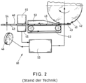
- the insertion wheel 42 for the capsules 43, 44 and the knife carrier 46 are once correctly set in their angular position relative to one another, so that the cut is made at the desired point relative to the capsules. Due to wear and tear of a format tape, which is also used, for example, in 2 is shown, however, a slow onset of slippage between the filter train 40 and the format belt 52 can occur during the course of production. The consequence of this is a slow, systematic departure of the capsules relative to the cut position of the filter 41.
- This problem can be solved with the aid of the measuring system in that, if the capsules systematically depart, the angular position between the insert wheel 52 and the knife carrier 46 is controlled by a cutting position control or position control 48 is readjusted, with the drive system supplying a master pulse, the so-called DCP (Double Cigarette Pulse), for readjusting the position of the insert wheel 42 .
- DCP Double Cigarette Pulse
- In 2 60 is another embodiment of a filter rod machine according to FIG EP 2 243 385 A2 shown schematically. Accordingly, the components insert wheel 42, microwave resonator 45 and the cutting device 46 are also shown.
- the insert wheel 42 has troughs into which only one capsule 43 is introduced in this exemplary embodiment. This is in contrast to the embodiment according to 1 , In each of which double depressions are provided, in which the two different or identical capsules are inserted one behind the other. The capsules are held in line 40 by suction air until they are transferred.
- a format device 53 is shown, which has a format tape 52, among other things.
- a format device is also in the embodiment according to FIG 1 available, but not shown there.
- the position control takes place as a function of a measured position value of the respectively inserted capsule 43 in the strand 40, which is generated by the microwave resonator 45 and is fed to a position controller 55.
- the position controller 55 controls or regulates the angular position of the insertion wheel 42 relative to the cutting device 46 so that the correct cutting position 54 can always be maintained, which is at a predetermined distance from the capsule 43 that has been introduced.
- FIG. 3 shows schematically and three-dimensionally a part of another known filter rod machine according to FIG EP 2 243 385 A2 .
- a two-rod machine is shown, ie a filter rod machine for processing two filter rods 40 and 40'.
- two insertion wheels 42, 42' are also provided, which are each driven by corresponding drive systems 47, 47'. In this case, too, the insertion wheels 42, 42' serve to insert capsules 43 into the filter rods 40, 40'.
- a bobbin is also shown, from which the covering material 62, 62' is pulled off after cutting.
- the wrapping material 62, 62' is fed to two format belts 52, 52'.
- the format tapes 52, 52' are driven by means of drive systems 64, 64'.
- the filter rods 40, 40' are placed on the format belts 52, 52' and guided through format devices 53, 53', in which the wrapping material strips 62, 62' are wound around the filter rods and also closed.
- a seam flattening device 63 in which the seams of the strip of wrapping material or the adhesive for sealing the seams are dried, in particular by the action of heat.
- the strands 40, 40' then pass through a microwave resonator 45', which has two passage openings for the strands 40, 40'.
- the microwave resonator 45' can be a microwave measuring device that consists of two microwave resonators that are decoupled from one another in order to enable very good measurement accuracy for the respective strand.
- microwave resonator 45 After the microwave resonator 45 or the microwave resonator device, there are two cutting devices 46, 46', which are each driven by drive systems 49 and 49'.
- the position control of the corresponding driven components namely the insertion wheels 42, 42', the format tapes 52 and 52' and the cutting device 46 and 46', is controlled via corresponding drive systems 47, 47'; 64, 64' and 49, 49'.
- the position control of the format tapes 52 and 52' includes a superimposed speed control.
- the position controller 48 receives the position of the respective capsules 43 in the respective strands from the microwave resonator 45'. This situation is further processed into control variables that are used to control the drive systems. In this way, the position, in particular the angular position, of the cutting devices 46, 46' can be regulated or controlled. Correspondingly, the angular position of the cutting devices 46, 46' relative to the speed or speeds of the format belts 52 and 52' can also be controlled or regulated. Finally, it is possible to control or regulate the angular position of the insertion wheels 42, 42' relative to the speed of the format tapes 52 and 52'.
- the position of the capsules 43 introduced into the filter rods 40, 40' is controlled or regulated in such a way that the capsules are always at the same distance in the conveying direction of the rods 40, 40' lie parallel in the two strands 40, 40'.
- the cutting devices 46 and 46' can cut the strands at the same time, and the run of the filter strands 40, 40' and the further processing of the cut-to-length filters are synchronized.
- a common cutting device can also be provided for both strands.
- a filter train 40 into which an insert wheel 42 inserts liquid-filled capsules 43, which it receives from a filling chute (no reference number), is conveyed towards an input of a microwave resonator, shown schematically.
- a microwave resonator shown schematically.
- a cylindrical resonator for example, according to DE 198 54 550 B4 arranged, which the filter train 40 passes through centrally.
- FIGs 5a) and 5b shows the case in which a capsule 43 is not arranged centrally in a section of a filter rod or in a cylindrical filter rod 10.
- this situation is shown in perspective, with a central target position being shown as the zero point of a Cartesian coordinate system, one axis of which runs through the central axis of symmetry of the cylindrical object and the other two perpendicular to it.
- An offset of the capsule 43 is in Figure 5a ) already recognizable.
- Figure 5b is a plan view of an end face of the filter rod 10 showing that the capsule 43 is highly eccentric and does not even touch the target position 12. Such incorrect positioning should lead to the exclusion of the filter rod 10 from further production.
- FIG DE 198 54 550 B4 represents the characteristics of the resonant microwave field in a hollow cylindrical microwave resonator 45 as shown in FIG DE 198 54 550 B4 is known. This is operated in the E 010 mode, so that the greatest field strength is in the centre.
- the solid straight arrows mean the E field lines (electric field lines) and the closed dashed field lines mean the (magnetic) H field lines.
- an open coaxial resonator 30 shown in detail schematically in cross section.
- the open coaxial resonator 30 is cylindrical in cross section and has a bottom 33 and a central conductor 34 .
- the end face opposite the bottom 33 is open with an opening 35 from which a microwave measuring field 32 exits, which is particularly strongly bundled at the point where the central conductor 35 exits.
- the strength of the microwave measuring field 32 decreases greatly as the distance from the opening 35 increases.
- a filter rod 10 or a filter rod with a capsule 43 is located just centrally above the opening 35 of the coaxial resonator 30 and thus the microwave field 32 is maximally influenced by the presence of the capsule 43 filled with liquid.
- In 8 shows the frequency curve of the amplitude A of the resonant microwave field 32 in the resonator.
- the resonance curve 36 represents the case without the capsule present.
- the resonance curve 36' shows the case with the capsule 43 present. It can be seen that the resonance maximum is shifted by a resonance shift, which is marked with a double arrow, and at lower frequencies the resonance curve 36 'is above the resonance curve 36.
- the measurement frequency 39 actually used is on the lower edge of the resonance curves 36, 36'.
- the resonant frequency and the damping and quality change accordingly in the excited oscillating system 8 are changed in the microwave field, the resonant frequency and the damping and quality change accordingly in the excited oscillating system 8 .
- Both variables can be determined and evaluated in the same way as in the previous system, for example by means of the power loss amplitude and the first derivation at a fixed measurement frequency.
- a transmission measurement S 21 or a reflection measurement S 11 can be used.
- a measurement according to the resonance sequence method, which is constructed in particular as a reflection measurement, is also possible according to the invention.
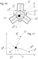
- FIG. 10 shows a cross-sectional representation of a star-shaped arrangement according to the invention of three open coaxial resonators 30 I-III , which are arranged around a filter rod 10 .
- the arrangement also applies in the same way in the event that instead of a filter rod 10 an endless filter rod 40 with capsules 43 is checked.
- the three microwave resonators 30 I-III are aligned with their respective openings towards the filter rod 10 and are arranged at angles of 120° to one another, ie they form an equilateral triangle. How out 10 can also be seen, the microwave measuring fields 32 I-III partially overlap one another. Therefore, different measurement frequencies are used to decouple them from each other.
- the object 43 is arranged highly eccentrically, as away from the central target position 12 and offset to the edge 11 of the filter rod 10 .
- the capsule 43 is thus located close to the entrance of the coaxial resonator 30 III and has a very strong influence on the microwave field 32 III .
- it is about the same distance from the side openings of the coaxial resonators 30 I and 30 ", so that their microwave fields 32 I and 32 II experience only comparatively weak changes.
- the result is a strong measurement signal for the open coaxial resonator 30 III and weak measurement signals for the coaxial resonators 30 I and 30 II .
- In 11 is a triangulation from the measurement results according to 10 represented graphically.
- crosses 31 I-III are the positions of the open coaxial resonators 30 I-III according to 10 designated.
- the lines emanating from the crosses have a length corresponding to a weighted measured respective distance 38 I-III . Since the measurement signals also depend on the filling level of the capsule 43 in addition to the respective distance, a corresponding weighting must be carried out.
- the various measurement signals first allow an assessment of the relative distances between the capsule 43 and the three microwave resonators 30 I-III in the form that the ratios of the distances are known, but not the absolute values. Then the distances are varied with the determined fixed distance ratios until the corresponding circles (cf. dashed lines in 11 ) intersect with the corresponding distances around positions 31 I-III at a common intersection. The point of intersection marks the transverse actual position 13 of the capsule 43. When the actual position 13 of the capsule 43 is known, conclusions can then be drawn from the measurement signals as to its filling state. For this purpose, the measurement signals are added up, for example weighted by distance, with the anisotropy of the emerging microwave measurement fields having to be taken into account.
- the longitudinal position in the strand or article can also be determined via the running direction and the time component of the measurement signal, for example according to the maximum degree of filling determined as a function of the current strand or article position. It can also be used to determine whether capsules or objects are missing or duplicated in places where an object should have been inserted.
Landscapes
- Physics & Mathematics (AREA)
- General Health & Medical Sciences (AREA)
- Health & Medical Sciences (AREA)
- Biochemistry (AREA)
- Chemical & Material Sciences (AREA)
- Analytical Chemistry (AREA)
- Life Sciences & Earth Sciences (AREA)
- Electromagnetism (AREA)
- General Physics & Mathematics (AREA)
- Immunology (AREA)
- Pathology (AREA)
- Toxicology (AREA)
- Manufacturing Of Cigar And Cigarette Tobacco (AREA)
Claims (13)
- Dispositif de mesure pour le contrôle d'au moins un article (10) ayant la forme d'une tige ou d'un boudin de matière (40), transporté dans le sens de l'axe longitudinal, de l'industrie de traitement du tabac, pour contrôler une position (13) d'au moins un objet (43, 44) inséré dans l'article (10) ou le boudin de matière (40), notamment d'une capsule (43, 44) remplie d'un liquide, à l'aide d'au moins un champ de mesure à micro-ondes (32I-III), caractérisé en ce qu'au moins deux, notamment au moins trois, résonateurs à micro-ondes (30I-III) avec des ouvertures latérales (35) sont disposés dans des positions différentes (31I-III), dans le sens de pourtour de l'article (10) ou du boudin de matière (40), autour de l'article (10) ou du boudin de matière (40) et appliquent chacun à l'article (10) ou au boudin de matière (40), à partir d'un côté, un champ de mesure à micro-ondes (32I-III), lesdits au moins deux résonateurs à micro-ondes (30I-III) étant configurés comme résonateurs coaxiaux (30I-III) ouverts, le côté ouvert des résonateurs coaxiaux (30 I-III) étant orienté vers l'article (10) ou le boudin de matière (40), une électronique de puissance reliée aux résonateurs à micro-ondes (30I-III) étant configurée pour appliquer aux résonateurs à micro-ondes (30I-III) des fréquences de mesure micro-ondes différentes.
- Dispositif de mesure selon la revendication 1, caractérisé en ce que trois résonateurs à micro-ondes (30 I-III) sont disposés dans une disposition à des angles égaux, notamment en forme d'étoile, autour de l'article (10) ou du boudin de matière (40).
- Dispositif de mesure selon la revendication 1 ou 2, caractérisé en ce que trois résonateurs à micro-ondes (30I-III) sont disposés dans la même position ou dans des positions différentes, dans la direction de l'axe longitudinal de l'article (10) ou du boudin de matière (40).
- Dispositif de mesure selon l'une des revendications 1 à 3, caractérisé en ce qu'une électronique de puissance reliée aux résonateurs à micro-ondes (30I-III) est configurée pour appliquer aux résonateurs à micro-ondes (30I-III) des fréquences de mesure micro-ondes entre 1 GHz et 10 GHz, notamment entre 4 GHz et 7 GHz.
- Dispositif de mesure selon l'une des revendications 1 à 4, caractérisé en ce que les résonateurs à micro-ondes (30I-III), notamment des résonateurs coaxiaux (30I-III) ouverts, présentent, pour un même diamètre, des longueurs et/ou formes différentes pour des fréquences de mesure micro-ondes différentes.
- Dispositif de mesure selon l'une des revendications 1 à 5, caractérisé en ce qu'un dispositif de guidage (14) pour guider l'article (10) ou le boudin de matière (40) est prévu dans la zone des résonateurs à micro-ondes (30I-III), à l'aide duquel une distance entre l'article (10) ou le boudin de matière (40) et les ouvertures (35) des résonateurs à micro-ondes (30I-III) peut être prédéterminée.
- Utilisation d'un dispositif de mesure selon l'une des revendications 1 à 6 pour contrôler au moins un article (10) ayant la forme d'une tige ou d'un boudin de matière (40), transporté dans le sens de l'axe longitudinal, de l'industrie de traitement du tabac, pour contrôler une position (13) d'au moins un objet (43, 44) inséré dans l'article (10) ou le boudin de matière (40), notamment d'une capsule (43, 44) remplie d'un liquide, notamment d'une position transversale (13) de l'objet (43, 44) dans l'article (10) ou boudin de matière (40) et/ou d'une distance radiale de l'objet d'un centre et/ou d'un bord (11) de l'article (10) ou boudin de matière (40).
- Machine de l'industrie de traitement du tabac, notamment machine pour boudins de filtre ou machine pour boudins de cigarettes, avec au moins un dispositif de mesure selon l'une des revendications 1 à 6 pour contrôler des articles ou un ou deux boudins de matière, notamment des boudins de filtre, ou des boudins de tabac ou de cigarette enveloppés.
- Procédé pour le contrôle d'au moins un article (10) ayant la forme d'une tige ou d'un boudin de matière (40), transporté dans le sens de l'axe longitudinal, de l'industrie de traitement du tabac, dans lequel est inséré au moins un objet (43, 44), notamment une capsule (43, 44) remplie d'un liquide, à l'aide d'un champ de mesure à micro-ondes (32, 32I-III) dans un dispositif de mesure selon l'une des revendications 1 à 6, caractérisé en ce que, pendant un transport dans la direction de l'axe longitudinal, de trois côtés différents, dans le sens du pourtour, un champ de mesure à micro-ondes (32I-III) respectif pénétrant radialement d'un côté et provenant chacun d'au moins un résonateur à micro-ondes (30I-III) latéralement ouvert, est appliqué à l'article (10) ou au boudin de matière (40), où sur la base des changements des signaux de mesure (37) respectifs des trois résonateurs à micro-ondes (30I-III), qui résultent de la présence d'un objet (43, 44) inséré dans l'article (10) ou le boudin de matière (40), au moins une caractéristique de l'objet (43, 44) est déterminée, les trois résonateurs à micro-ondes (30I-III) étant configurés comme résonateurs coaxiaux (30I-III) ouverts, le côté ouvert du résonateur coaxial (30I-III) étant orienté vers l'article (10) ou le boudin de matière (40), et la caractéristique déterminée étant une position transversale (13) de l'objet dans l'article (10) ou boudin de matière (40) et/ou une distance radiale de l'objet (43, 44) d'un centre et/ou d'un bord (11) de l'article (10) ou boudin de matière (40) et/ou une position de l'objet (43, 44) dans la direction de l'axe longitudinal dans l'article (10) ou le boudin de matière (40).
- Procédé selon la revendication 9, caractérisé en ce qu'une caractéristique déterminée est une quantité de remplissage, un taux de remplissage, un état d'endommagement et/ou une absence d'un objet (43, 44) ou un surplus d'objets (43, 44) insérés dans une position dans la direction de l'axe longitudinal dans l'article (10) ou le boudin de matière (40).
- Procédé selon la revendication 9 ou 10, caractérisé en ce que la détermination est mise en oeuvre à l'aide d'une triangulation et/ou d'une table de recherche qui est ou a été déterminée par simulation ou de manière empirique.
- Procédé selon l'une des revendications 9 à 11, caractérisé en ce qu'un article (10) ou une section d'un boudin de matière (40) qui contient un objet (43, 44) ne respectant pas une valeur limite prédéterminée ou pouvant être prédéterminée, est exclu de la suite du traitement et/ou est sorti du procédé de fabrication, notamment par soufflage.
- Procédé selon l'une des revendications 9 à 12, caractérisé en ce que dans un système auto-apprenant, des valeurs limites pour des objets (43, 44) réglementaires sont adaptées pour une production, notamment pour chaque production, pour les premiers objets (43, 44), notamment dix à cinquante, dans le boudin de matière ou dans les articles, une première plage est fixée pour des valeurs limites et ensuite, une moyenne courante sur plusieurs objets (43, 44), notamment cinq cents à mille objets, dans le boudin de matière ou dans les articles est utilisée pour l'adaptation des valeurs limites.
Priority Applications (1)
| Application Number | Priority Date | Filing Date | Title |
|---|---|---|---|
| PL14151368.9T PL2762016T5 (pl) | 2013-01-30 | 2014-01-16 | Przyrząd pomiarowy, urządzenie i sposób przemysłu tytoniowego |
Applications Claiming Priority (1)
| Application Number | Priority Date | Filing Date | Title |
|---|---|---|---|
| DE102013201512.7A DE102013201512A1 (de) | 2013-01-30 | 2013-01-30 | Messvorrichtung, Maschine und Verfahren der Tabak verarbeitenden Industrie |
Publications (4)
| Publication Number | Publication Date |
|---|---|
| EP2762016A2 EP2762016A2 (fr) | 2014-08-06 |
| EP2762016A3 EP2762016A3 (fr) | 2016-01-20 |
| EP2762016B1 EP2762016B1 (fr) | 2018-09-19 |
| EP2762016B2 true EP2762016B2 (fr) | 2023-06-21 |
Family
ID=49920271
Family Applications (1)
| Application Number | Title | Priority Date | Filing Date |
|---|---|---|---|
| EP14151368.9A Active EP2762016B2 (fr) | 2013-01-30 | 2014-01-16 | Dispositif de mesure, machine et procédé de l'industrie de traitement du tabac |
Country Status (4)
| Country | Link |
|---|---|
| EP (1) | EP2762016B2 (fr) |
| CN (1) | CN103960773B (fr) |
| DE (1) | DE102013201512A1 (fr) |
| PL (1) | PL2762016T5 (fr) |
Families Citing this family (10)
| Publication number | Priority date | Publication date | Assignee | Title |
|---|---|---|---|---|
| EP3238552B8 (fr) * | 2014-12-26 | 2021-10-27 | Japan Tobacco Inc. | Appareil d'inspection de filtre |
| US10045558B2 (en) | 2015-02-12 | 2018-08-14 | Hauni Maschinenbau Gmbh | Method and apparatus for inserting oriented objects into a filter rod |
| CN107303013B (zh) * | 2016-04-20 | 2019-11-26 | 上海烟草集团有限责任公司 | 胶囊滤棒剥离装置、剥离方法以及胶囊位置检测方法 |
| DE102016114642A1 (de) | 2016-08-08 | 2018-02-08 | Hauni Maschinenbau Gmbh | Verfahren und Vorrichtung zum Erkennen und/oder Prüfen eines in ein stab- oder strangförmiges Produkt der Tabak verarbeitenden Industrie eingelegten Objekts |
| DE102017106133A1 (de) * | 2017-03-22 | 2018-09-27 | Hauni Maschinenbau Gmbh | Verfahren zum Steuern eines Strangabschneiders und Strangmaschine der Tabak verarbeitenden Industrie |
| DE102018105363B4 (de) * | 2018-03-08 | 2021-03-18 | Hauni Maschinenbau Gmbh | Vorrichtung zum Prüfen, Bearbeiten und/oder Fördern von Artikeln der Tabak verarbeitenden Industrie |
| IT201800006412A1 (it) * | 2018-06-18 | 2019-12-18 | Unità e metodo di rilevazione per l’industria del tabacco | |
| DE202019103894U1 (de) * | 2019-07-15 | 2019-09-23 | Tews Elektronik Gmbh & Co. Kg | Zigarettenmaschine mit einem Saugbandförderer |
| PL3918928T3 (pl) * | 2020-06-03 | 2023-05-08 | International Tobacco Machinery Poland Sp. Z O.O. | Sposób i urządzenie do wytwarzania sztabek |
| EP3918929A1 (fr) * | 2020-06-03 | 2021-12-08 | International Tobacco Machinery Poland SP. Z O.O. | Procédé et appareil de fabrication de tiges |
Citations (4)
| Publication number | Priority date | Publication date | Assignee | Title |
|---|---|---|---|---|
| CH604163A5 (en) † | 1976-08-04 | 1978-08-31 | Gardiol Fred E | Microwave moisture meter using resonant cavity |
| US5397993A (en) † | 1990-02-10 | 1995-03-14 | Tews; Manfred | Method for measuring the material moisture content of a material under test using microwaves |
| DE202005010375U1 (de) † | 2005-07-01 | 2005-10-20 | Tews Elektronik Dipl.-Ing. Manfred Tews | Vorrichtung zum Detektieren und Aussondern von fehlerhaften Zigaretten |
| DE202007018481U1 (de) † | 2007-08-28 | 2008-09-11 | Tews Elektronik Dipl.-Ing. Manfred Tews | Vorrichtung zur Messung eines Feuchtewertes von dielektrischen Stoffen |
Family Cites Families (9)
| Publication number | Priority date | Publication date | Assignee | Title |
|---|---|---|---|---|
| DE19854550C5 (de) * | 1998-11-26 | 2011-03-17 | Hauni Maschinenbau Ag | Resonatorgehäuse für Mikrowellen |
| DE10100664A1 (de) * | 2001-01-09 | 2002-07-11 | Hauni Maschinenbau Ag | Verfahren zum Prüfen eines Produktionsmaterials |
| DE10112499B4 (de) * | 2001-03-15 | 2010-08-19 | Hauni Maschinenbau Ag | Resonatoreinrichtung, insbesondere Mikrowellenresonatoreinrichtung |
| DE102004017597B4 (de) * | 2004-04-07 | 2006-06-22 | Hauni Maschinenbau Ag | Resonatorgehäuse für Mikrowellen |
| CN201060170Y (zh) * | 2007-06-20 | 2008-05-14 | 中国电子科技集团公司第四十一研究所 | 烟支密度微波检测装置 |
| DE102007029908A1 (de) * | 2007-06-28 | 2009-01-02 | Tews Elektronik Dipl.-Ing. Manfred Tews | Vorrichtung und Verfahren zur Masse- und/oder Feuchtemessung von dielektrischen Objekten |
| DE102009017963A1 (de) | 2009-04-21 | 2010-10-28 | Hauni Maschinenbau Ag | Kapselüberwachung und Kapselpositionsregelung in Filtern der Tabak verarbeitenden Industrie |
| US9131730B2 (en) * | 2010-01-07 | 2015-09-15 | Aiger Group Ag | System and apparatus for registration of different objects in rod shaped articles |
| DE102011006416B4 (de) * | 2011-03-30 | 2020-08-13 | Hauni Maschinenbau Gmbh | Verfahren und System zum Herstellen eines Filterstrangs |
-
2013
- 2013-01-30 DE DE102013201512.7A patent/DE102013201512A1/de not_active Ceased
-
2014
- 2014-01-16 PL PL14151368.9T patent/PL2762016T5/pl unknown
- 2014-01-16 EP EP14151368.9A patent/EP2762016B2/fr active Active
- 2014-01-29 CN CN201410043278.7A patent/CN103960773B/zh active Active
Patent Citations (4)
| Publication number | Priority date | Publication date | Assignee | Title |
|---|---|---|---|---|
| CH604163A5 (en) † | 1976-08-04 | 1978-08-31 | Gardiol Fred E | Microwave moisture meter using resonant cavity |
| US5397993A (en) † | 1990-02-10 | 1995-03-14 | Tews; Manfred | Method for measuring the material moisture content of a material under test using microwaves |
| DE202005010375U1 (de) † | 2005-07-01 | 2005-10-20 | Tews Elektronik Dipl.-Ing. Manfred Tews | Vorrichtung zum Detektieren und Aussondern von fehlerhaften Zigaretten |
| DE202007018481U1 (de) † | 2007-08-28 | 2008-09-11 | Tews Elektronik Dipl.-Ing. Manfred Tews | Vorrichtung zur Messung eines Feuchtewertes von dielektrischen Stoffen |
Non-Patent Citations (2)
| Title |
|---|
| BORIS TSENTSIPER: "APPLICATION OF OPEN COAXIAL RESONATOR AS SENSOR FOR MICROWAVE MOISTURE METER", 3RD WORKSHOP ON ELECTROMAGNETIC WAVE INTERACTION WITH WATER AND MOIST SUBSTANCES, 199904011, pages 156 - 160 † |
| J R Dizon: "A combined near-field scanning microwave microscope and transport measurement system for characterizing dissipation in conducting and high-Tc superconducting films at variable temperatures", PhD thesis, University of Kansas, 2006 † |
Also Published As
| Publication number | Publication date |
|---|---|
| PL2762016T3 (pl) | 2019-02-28 |
| EP2762016B1 (fr) | 2018-09-19 |
| EP2762016A2 (fr) | 2014-08-06 |
| PL2762016T5 (pl) | 2023-09-04 |
| CN103960773A (zh) | 2014-08-06 |
| CN103960773B (zh) | 2017-04-12 |
| EP2762016A3 (fr) | 2016-01-20 |
| DE102013201512A1 (de) | 2014-08-14 |
Similar Documents
| Publication | Publication Date | Title |
|---|---|---|
| EP2762016B2 (fr) | Dispositif de mesure, machine et procédé de l'industrie de traitement du tabac | |
| EP2243385B1 (fr) | Surveillance de capsule dans des filtres de l'industrie de traitement du tabac | |
| EP2848133B1 (fr) | Système et procédé de contrôle d'articles en forme de tige de l'industrie de traitement du tabac | |
| EP3552500B1 (fr) | Dispositif et procédé de fabrication de segments du tabac en forme de tige dotés respectivement d'une bande chauffante | |
| DE102011006416B4 (de) | Verfahren und System zum Herstellen eines Filterstrangs | |
| EP2674044B1 (fr) | Procédé et dispositif de détection de défauts d'homogénéité d'une tige de matériau de l'industrie de traitement du tabac | |
| EP3354143B1 (fr) | Procédé et dispositif de surveillance et de fabrication d'un boudin de filtre de l'industrie de traitement du tabac | |
| EP3497438B1 (fr) | Dispositif de mesure et procédé permettant de détecter des éléments électroconducteurs dans des produits ainsi que machine de fabrication de produits de l'industrie du traitement du tabac | |
| EP2769632B2 (fr) | Procédé de mesure et dispositif de mesure pour l'enregistrement de la position d'un objet dans une tige de filtre transportée en direction axiale longitudinale et machine de l'industrie de traitement du tabac | |
| DE102013201511B3 (de) | Anordnung und Verfahren zur Überprüfung von stabförmigen Produkten der Tabak verarbeitenden Industrie | |
| EP2404512B1 (fr) | Dispositif de fabrication de cigarettes dans l'industrie de traitement du tabac | |
| EP2965640B1 (fr) | Controle d'articles en forme de tige, en particulier cigarettes a filtre | |
| EP3297461A1 (fr) | Transporteur à bande d'aspiration et machine de fabrication de boudins de l'industrie de transformation du tabac, utilisation et procédé de mesure des propriétés matérielles d'un boudin de matières de l'industrie de transformation du tabac | |
| DE102010043474A1 (de) | Verfahren und Vorrichtung zum Einlegen von Objekten in einen Filterstrang der Tabak verarbeitenden Industrie | |
| WO2014005677A1 (fr) | Système de mesure d'au moins une propriété d'au moins d'un article en forme de bâtonnet de l'industrie de transformation du tabac | |
| EP2661971B1 (fr) | Fabrication de cigarettes à filtre | |
| EP3281536B1 (fr) | Procédé et dispositif de détection et/ou de contrôle d'un produit inséré dans un produit en forme de tige ou de barre provenant de l'industrie du tabac | |
| EP2572594A2 (fr) | Boîtier de résonateur pour micro-ondes passé par un tronçon de matière pour déterminer des attributs du tronçon de matière | |
| EP2606754B1 (fr) | Procédé de mesure de la position de segments avec des substances absorbantes dans des tiges à filtre multi-segment de l'industrie de traitement du tabac | |
| DE10117081A1 (de) | Vorrichtung und Verfahren zur Erzeugung einer Aussage über die Eigenschaft(en) eines Faserstranges | |
| EP3378338B1 (fr) | Procédé de commande d'un dispositif de coupe de boudin et machine à boudin de l'industrie de traitement du tabac | |
| DE102014212497A1 (de) | Verfahren und Vorrichtung und Maschine zur Herstellung eines Filterstrangs der Tabak verarbeitenden Industrie | |
| EP3485745A1 (fr) | Procédé et dispositif de fabrication de bâtonnets chauffants |
Legal Events
| Date | Code | Title | Description |
|---|---|---|---|
| PUAI | Public reference made under article 153(3) epc to a published international application that has entered the european phase |
Free format text: ORIGINAL CODE: 0009012 |
|
| 17P | Request for examination filed |
Effective date: 20140116 |
|
| AK | Designated contracting states |
Kind code of ref document: A2 Designated state(s): AL AT BE BG CH CY CZ DE DK EE ES FI FR GB GR HR HU IE IS IT LI LT LU LV MC MK MT NL NO PL PT RO RS SE SI SK SM TR |
|
| AX | Request for extension of the european patent |
Extension state: BA ME |
|
| PUAL | Search report despatched |
Free format text: ORIGINAL CODE: 0009013 |
|
| AK | Designated contracting states |
Kind code of ref document: A3 Designated state(s): AL AT BE BG CH CY CZ DE DK EE ES FI FR GB GR HR HU IE IS IT LI LT LU LV MC MK MT NL NO PL PT RO RS SE SI SK SM TR |
|
| AX | Request for extension of the european patent |
Extension state: BA ME |
|
| RIC1 | Information provided on ipc code assigned before grant |
Ipc: A24D 3/02 20060101ALI20151214BHEP Ipc: G01N 22/04 20060101ALI20151214BHEP Ipc: A24C 5/34 20060101AFI20151214BHEP |
|
| RAP1 | Party data changed (applicant data changed or rights of an application transferred) |
Owner name: HAUNI MASCHINENBAU GMBH |
|
| R17P | Request for examination filed (corrected) |
Effective date: 20160707 |
|
| RBV | Designated contracting states (corrected) |
Designated state(s): AL AT BE BG CH CY CZ DE DK EE ES FI FR GB GR HR HU IE IS IT LI LT LU LV MC MK MT NL NO PL PT RO RS SE SI SK SM TR |
|
| GRAP | Despatch of communication of intention to grant a patent |
Free format text: ORIGINAL CODE: EPIDOSNIGR1 |
|
| STAA | Information on the status of an ep patent application or granted ep patent |
Free format text: STATUS: GRANT OF PATENT IS INTENDED |
|
| RIC1 | Information provided on ipc code assigned before grant |
Ipc: G01N 22/04 20060101ALI20180409BHEP Ipc: A24C 5/34 20060101AFI20180409BHEP Ipc: A24D 3/02 20060101ALI20180409BHEP |
|
| INTG | Intention to grant announced |
Effective date: 20180507 |
|
| GRAS | Grant fee paid |
Free format text: ORIGINAL CODE: EPIDOSNIGR3 |
|
| GRAA | (expected) grant |
Free format text: ORIGINAL CODE: 0009210 |
|
| STAA | Information on the status of an ep patent application or granted ep patent |
Free format text: STATUS: THE PATENT HAS BEEN GRANTED |
|
| AK | Designated contracting states |
Kind code of ref document: B1 Designated state(s): AL AT BE BG CH CY CZ DE DK EE ES FI FR GB GR HR HU IE IS IT LI LT LU LV MC MK MT NL NO PL PT RO RS SE SI SK SM TR |
|
| REG | Reference to a national code |
Ref country code: GB Ref legal event code: FG4D Free format text: NOT ENGLISH |
|
| REG | Reference to a national code |
Ref country code: CH Ref legal event code: EP |
|
| REG | Reference to a national code |
Ref country code: AT Ref legal event code: REF Ref document number: 1042229 Country of ref document: AT Kind code of ref document: T Effective date: 20181015 |
|
| REG | Reference to a national code |
Ref country code: IE Ref legal event code: FG4D Free format text: LANGUAGE OF EP DOCUMENT: GERMAN |
|
| REG | Reference to a national code |
Ref country code: DE Ref legal event code: R096 Ref document number: 502014009494 Country of ref document: DE |
|
| REG | Reference to a national code |
Ref country code: NL Ref legal event code: FP |
|
| PG25 | Lapsed in a contracting state [announced via postgrant information from national office to epo] |
Ref country code: SE Free format text: LAPSE BECAUSE OF FAILURE TO SUBMIT A TRANSLATION OF THE DESCRIPTION OR TO PAY THE FEE WITHIN THE PRESCRIBED TIME-LIMIT Effective date: 20180919 Ref country code: LT Free format text: LAPSE BECAUSE OF FAILURE TO SUBMIT A TRANSLATION OF THE DESCRIPTION OR TO PAY THE FEE WITHIN THE PRESCRIBED TIME-LIMIT Effective date: 20180919 Ref country code: NO Free format text: LAPSE BECAUSE OF FAILURE TO SUBMIT A TRANSLATION OF THE DESCRIPTION OR TO PAY THE FEE WITHIN THE PRESCRIBED TIME-LIMIT Effective date: 20181219 Ref country code: RS Free format text: LAPSE BECAUSE OF FAILURE TO SUBMIT A TRANSLATION OF THE DESCRIPTION OR TO PAY THE FEE WITHIN THE PRESCRIBED TIME-LIMIT Effective date: 20180919 Ref country code: GR Free format text: LAPSE BECAUSE OF FAILURE TO SUBMIT A TRANSLATION OF THE DESCRIPTION OR TO PAY THE FEE WITHIN THE PRESCRIBED TIME-LIMIT Effective date: 20181220 Ref country code: FI Free format text: LAPSE BECAUSE OF FAILURE TO SUBMIT A TRANSLATION OF THE DESCRIPTION OR TO PAY THE FEE WITHIN THE PRESCRIBED TIME-LIMIT Effective date: 20180919 |
|
| REG | Reference to a national code |
Ref country code: LT Ref legal event code: MG4D |
|
| PG25 | Lapsed in a contracting state [announced via postgrant information from national office to epo] |
Ref country code: HR Free format text: LAPSE BECAUSE OF FAILURE TO SUBMIT A TRANSLATION OF THE DESCRIPTION OR TO PAY THE FEE WITHIN THE PRESCRIBED TIME-LIMIT Effective date: 20180919 Ref country code: LV Free format text: LAPSE BECAUSE OF FAILURE TO SUBMIT A TRANSLATION OF THE DESCRIPTION OR TO PAY THE FEE WITHIN THE PRESCRIBED TIME-LIMIT Effective date: 20180919 Ref country code: AL Free format text: LAPSE BECAUSE OF FAILURE TO SUBMIT A TRANSLATION OF THE DESCRIPTION OR TO PAY THE FEE WITHIN THE PRESCRIBED TIME-LIMIT Effective date: 20180919 |
|
| PG25 | Lapsed in a contracting state [announced via postgrant information from national office to epo] |
Ref country code: IS Free format text: LAPSE BECAUSE OF FAILURE TO SUBMIT A TRANSLATION OF THE DESCRIPTION OR TO PAY THE FEE WITHIN THE PRESCRIBED TIME-LIMIT Effective date: 20190119 Ref country code: ES Free format text: LAPSE BECAUSE OF FAILURE TO SUBMIT A TRANSLATION OF THE DESCRIPTION OR TO PAY THE FEE WITHIN THE PRESCRIBED TIME-LIMIT Effective date: 20180919 Ref country code: EE Free format text: LAPSE BECAUSE OF FAILURE TO SUBMIT A TRANSLATION OF THE DESCRIPTION OR TO PAY THE FEE WITHIN THE PRESCRIBED TIME-LIMIT Effective date: 20180919 Ref country code: CZ Free format text: LAPSE BECAUSE OF FAILURE TO SUBMIT A TRANSLATION OF THE DESCRIPTION OR TO PAY THE FEE WITHIN THE PRESCRIBED TIME-LIMIT Effective date: 20180919 Ref country code: RO Free format text: LAPSE BECAUSE OF FAILURE TO SUBMIT A TRANSLATION OF THE DESCRIPTION OR TO PAY THE FEE WITHIN THE PRESCRIBED TIME-LIMIT Effective date: 20180919 |
|
| PG25 | Lapsed in a contracting state [announced via postgrant information from national office to epo] |
Ref country code: SM Free format text: LAPSE BECAUSE OF FAILURE TO SUBMIT A TRANSLATION OF THE DESCRIPTION OR TO PAY THE FEE WITHIN THE PRESCRIBED TIME-LIMIT Effective date: 20180919 Ref country code: PT Free format text: LAPSE BECAUSE OF FAILURE TO SUBMIT A TRANSLATION OF THE DESCRIPTION OR TO PAY THE FEE WITHIN THE PRESCRIBED TIME-LIMIT Effective date: 20190119 Ref country code: SK Free format text: LAPSE BECAUSE OF FAILURE TO SUBMIT A TRANSLATION OF THE DESCRIPTION OR TO PAY THE FEE WITHIN THE PRESCRIBED TIME-LIMIT Effective date: 20180919 |
|
| REG | Reference to a national code |
Ref country code: DE Ref legal event code: R026 Ref document number: 502014009494 Country of ref document: DE |
|
| PLBI | Opposition filed |
Free format text: ORIGINAL CODE: 0009260 |
|
| PLAX | Notice of opposition and request to file observation + time limit sent |
Free format text: ORIGINAL CODE: EPIDOSNOBS2 |
|
| 26 | Opposition filed |
Opponent name: G.D S.P.A. Effective date: 20190619 |
|
| PG25 | Lapsed in a contracting state [announced via postgrant information from national office to epo] |
Ref country code: DK Free format text: LAPSE BECAUSE OF FAILURE TO SUBMIT A TRANSLATION OF THE DESCRIPTION OR TO PAY THE FEE WITHIN THE PRESCRIBED TIME-LIMIT Effective date: 20180919 |
|
| PG25 | Lapsed in a contracting state [announced via postgrant information from national office to epo] |
Ref country code: MC Free format text: LAPSE BECAUSE OF FAILURE TO SUBMIT A TRANSLATION OF THE DESCRIPTION OR TO PAY THE FEE WITHIN THE PRESCRIBED TIME-LIMIT Effective date: 20180919 |
|
| GBPC | Gb: european patent ceased through non-payment of renewal fee |
Effective date: 20190116 |
|
| PG25 | Lapsed in a contracting state [announced via postgrant information from national office to epo] |
Ref country code: LU Free format text: LAPSE BECAUSE OF NON-PAYMENT OF DUE FEES Effective date: 20190116 |
|
| REG | Reference to a national code |
Ref country code: BE Ref legal event code: MM Effective date: 20190131 |
|
| REG | Reference to a national code |
Ref country code: IE Ref legal event code: MM4A |
|
| PG25 | Lapsed in a contracting state [announced via postgrant information from national office to epo] |
Ref country code: FR Free format text: LAPSE BECAUSE OF NON-PAYMENT OF DUE FEES Effective date: 20190131 Ref country code: SI Free format text: LAPSE BECAUSE OF FAILURE TO SUBMIT A TRANSLATION OF THE DESCRIPTION OR TO PAY THE FEE WITHIN THE PRESCRIBED TIME-LIMIT Effective date: 20180919 |
|
| PLBB | Reply of patent proprietor to notice(s) of opposition received |
Free format text: ORIGINAL CODE: EPIDOSNOBS3 |
|
| PG25 | Lapsed in a contracting state [announced via postgrant information from national office to epo] |
Ref country code: BE Free format text: LAPSE BECAUSE OF NON-PAYMENT OF DUE FEES Effective date: 20190131 |
|
| PG25 | Lapsed in a contracting state [announced via postgrant information from national office to epo] |
Ref country code: GB Free format text: LAPSE BECAUSE OF NON-PAYMENT OF DUE FEES Effective date: 20190116 |
|
| PG25 | Lapsed in a contracting state [announced via postgrant information from national office to epo] |
Ref country code: IE Free format text: LAPSE BECAUSE OF NON-PAYMENT OF DUE FEES Effective date: 20190116 |
|
| REG | Reference to a national code |
Ref country code: AT Ref legal event code: MM01 Ref document number: 1042229 Country of ref document: AT Kind code of ref document: T Effective date: 20190116 |
|
| PG25 | Lapsed in a contracting state [announced via postgrant information from national office to epo] |
Ref country code: TR Free format text: LAPSE BECAUSE OF FAILURE TO SUBMIT A TRANSLATION OF THE DESCRIPTION OR TO PAY THE FEE WITHIN THE PRESCRIBED TIME-LIMIT Effective date: 20180919 |
|
| PG25 | Lapsed in a contracting state [announced via postgrant information from national office to epo] |
Ref country code: AT Free format text: LAPSE BECAUSE OF NON-PAYMENT OF DUE FEES Effective date: 20190116 |
|
| PG25 | Lapsed in a contracting state [announced via postgrant information from national office to epo] |
Ref country code: MT Free format text: LAPSE BECAUSE OF FAILURE TO SUBMIT A TRANSLATION OF THE DESCRIPTION OR TO PAY THE FEE WITHIN THE PRESCRIBED TIME-LIMIT Effective date: 20180919 |
|
| PLCK | Communication despatched that opposition was rejected |
Free format text: ORIGINAL CODE: EPIDOSNREJ1 |
|
| APBM | Appeal reference recorded |
Free format text: ORIGINAL CODE: EPIDOSNREFNO |
|
| APBP | Date of receipt of notice of appeal recorded |
Free format text: ORIGINAL CODE: EPIDOSNNOA2O |
|
| APAH | Appeal reference modified |
Free format text: ORIGINAL CODE: EPIDOSCREFNO |
|
| PG25 | Lapsed in a contracting state [announced via postgrant information from national office to epo] |
Ref country code: CY Free format text: LAPSE BECAUSE OF FAILURE TO SUBMIT A TRANSLATION OF THE DESCRIPTION OR TO PAY THE FEE WITHIN THE PRESCRIBED TIME-LIMIT Effective date: 20180919 |
|
| APBQ | Date of receipt of statement of grounds of appeal recorded |
Free format text: ORIGINAL CODE: EPIDOSNNOA3O |
|
| PG25 | Lapsed in a contracting state [announced via postgrant information from national office to epo] |
Ref country code: HU Free format text: LAPSE BECAUSE OF FAILURE TO SUBMIT A TRANSLATION OF THE DESCRIPTION OR TO PAY THE FEE WITHIN THE PRESCRIBED TIME-LIMIT; INVALID AB INITIO Effective date: 20140116 |
|
| PG25 | Lapsed in a contracting state [announced via postgrant information from national office to epo] |
Ref country code: MK Free format text: LAPSE BECAUSE OF FAILURE TO SUBMIT A TRANSLATION OF THE DESCRIPTION OR TO PAY THE FEE WITHIN THE PRESCRIBED TIME-LIMIT Effective date: 20180919 |
|
| REG | Reference to a national code |
Ref country code: DE Ref legal event code: R081 Ref document number: 502014009494 Country of ref document: DE Owner name: KOERBER TECHNOLOGIES GMBH, DE Free format text: FORMER OWNER: HAUNI MASCHINENBAU GMBH, 21033 HAMBURG, DE |
|
| REG | Reference to a national code |
Ref country code: NL Ref legal event code: HC Owner name: KOERBER TECHNOLOGIES GMBH; DE Free format text: DETAILS ASSIGNMENT: CHANGE OF OWNER(S), CHANGE OF OWNER(S) NAME; FORMER OWNER NAME: HAUNI MASCHINENBAU GMBH Effective date: 20221025 |
|
| RAP4 | Party data changed (patent owner data changed or rights of a patent transferred) |
Owner name: KOERBER TECHNOLOGIES GMBH |
|
| APBU | Appeal procedure closed |
Free format text: ORIGINAL CODE: EPIDOSNNOA9O |
|
| PUAH | Patent maintained in amended form |
Free format text: ORIGINAL CODE: 0009272 |
|
| STAA | Information on the status of an ep patent application or granted ep patent |
Free format text: STATUS: PATENT MAINTAINED AS AMENDED |
|
| 27A | Patent maintained in amended form |
Effective date: 20230621 |
|
| AK | Designated contracting states |
Kind code of ref document: B2 Designated state(s): AL AT BE BG CH CY CZ DE DK EE ES FI FR GB GR HR HU IE IS IT LI LT LU LV MC MK MT NL NO PL PT RO RS SE SI SK SM TR |
|
| REG | Reference to a national code |
Ref country code: DE Ref legal event code: R102 Ref document number: 502014009494 Country of ref document: DE |
|
| P01 | Opt-out of the competence of the unified patent court (upc) registered |
Effective date: 20230616 |
|
| REG | Reference to a national code |
Ref country code: NL Ref legal event code: FP |
|
| PGFP | Annual fee paid to national office [announced via postgrant information from national office to epo] |
Ref country code: DE Payment date: 20250130 Year of fee payment: 12 |
|
| PGFP | Annual fee paid to national office [announced via postgrant information from national office to epo] |
Ref country code: BG Payment date: 20250128 Year of fee payment: 12 |
|
| PGFP | Annual fee paid to national office [announced via postgrant information from national office to epo] |
Ref country code: CH Payment date: 20250201 Year of fee payment: 12 |
|
| PGFP | Annual fee paid to national office [announced via postgrant information from national office to epo] |
Ref country code: IT Payment date: 20250129 Year of fee payment: 12 |
|
| PGFP | Annual fee paid to national office [announced via postgrant information from national office to epo] |
Ref country code: PL Payment date: 20251219 Year of fee payment: 13 |
|
| REG | Reference to a national code |
Ref country code: CH Ref legal event code: U11 Free format text: ST27 STATUS EVENT CODE: U-0-0-U10-U11 (AS PROVIDED BY THE NATIONAL OFFICE) Effective date: 20260201 |
|
| PGFP | Annual fee paid to national office [announced via postgrant information from national office to epo] |
Ref country code: NL Payment date: 20260123 Year of fee payment: 13 |