EP2762016B2 - Measuring device, machine and method for the tobacco processing industry - Google Patents
Measuring device, machine and method for the tobacco processing industry Download PDFInfo
- Publication number
- EP2762016B2 EP2762016B2 EP14151368.9A EP14151368A EP2762016B2 EP 2762016 B2 EP2762016 B2 EP 2762016B2 EP 14151368 A EP14151368 A EP 14151368A EP 2762016 B2 EP2762016 B2 EP 2762016B2
- Authority
- EP
- European Patent Office
- Prior art keywords
- strand
- article
- iii
- microwave
- resonators
- Prior art date
- Legal status (The legal status is an assumption and is not a legal conclusion. Google has not performed a legal analysis and makes no representation as to the accuracy of the status listed.)
- Active
Links
Images


Classifications
-
- A—HUMAN NECESSITIES
- A24—TOBACCO; CIGARS; CIGARETTES; SIMULATED SMOKING DEVICES; SMOKERS' REQUISITES
- A24C—MACHINES FOR MAKING CIGARS OR CIGARETTES
- A24C5/00—Making cigarettes; Making tipping materials for, or attaching filters or mouthpieces to, cigars or cigarettes
- A24C5/32—Separating, ordering, counting or examining cigarettes; Regulating the feeding of tobacco according to rod or cigarette condition
- A24C5/34—Examining cigarettes or the rod, e.g. for regulating the feeding of tobacco; Removing defective cigarettes
- A24C5/3412—Examining cigarettes or the rod, e.g. for regulating the feeding of tobacco; Removing defective cigarettes by means of light, radiation or electrostatic fields
-
- A—HUMAN NECESSITIES
- A24—TOBACCO; CIGARS; CIGARETTES; SIMULATED SMOKING DEVICES; SMOKERS' REQUISITES
- A24D—CIGARS; CIGARETTES; TOBACCO SMOKE FILTERS; MOUTHPIECES OF CIGARS OR CIGARETTES; MANUFACTURE OF TOBACCO SMOKE FILTERS OR MOUTHPIECES
- A24D3/00—Tobacco smoke filters, e.g. filter tips or filtering inserts; Filters specially adapted for simulated smoking devices; Mouthpieces of cigars or cigarettes
- A24D3/02—Manufacture of tobacco smoke filters
- A24D3/0204—Preliminary operations before the filter rod forming process, e.g. crimping, blooming
- A24D3/0212—Applying additives to filter materials
- A24D3/0216—Applying additives to filter materials the additive being in the form of capsules, beads or the like
-
- G—PHYSICS
- G01—MEASURING; TESTING
- G01N—INVESTIGATING OR ANALYSING MATERIALS BY DETERMINING THEIR CHEMICAL OR PHYSICAL PROPERTIES
- G01N22/00—Investigating or analysing materials by the use of microwaves or radio waves, i.e. electromagnetic waves with a wavelength of one millimetre or more
- G01N22/04—Investigating moisture content
Definitions
- the invention relates to a measuring device for checking at least one rod-shaped article or strand of material conveyed along the longitudinal axis in the tobacco processing industry for checking the position of at least one object inserted into the article or the strand of material, in particular a liquid-filled capsule, by means of at least one microwave measuring field, a use and a machine for tobacco processing industry.
- the invention further relates to a method for checking at least one rod-shaped article or strand of material conveyed along the longitudinal axis of the tobacco processing industry, in which at least one object, in particular a liquid-filled capsule, is inserted, by means of at least one microwave measuring field.
- the invention thus relates to the production of an object-filled filter rod for rod-shaped articles in the tobacco processing industry, in particular for filter cigarettes.
- the filter strand is cut into individual filter rods.
- the filter strand or the cut-to-length filter rods contain one or more objects that influence the smoke or filter properties as an essential component.
- the objects are, in particular, capsules with a solid shell that are filled with a liquid.
- the liquid usually contains flavorings or fragrances, for example menthol.
- a smoker breaks open the capsule before smoking by pressing on the filter and then lights the cigarette. The pressure on the capsule in the filter releases the liquid so that the aroma of the liquid unfolds. This procedure offers a particularly intense or fresh taste experience.
- Corresponding capsules usually have a diameter of approx. 3.5 mm, but can also be smaller or larger.
- the disclosed device includes one or more sensors that determine the composition of rod segments and a processor that receives the signals from the sensor or sensors and makes a comparison between the signals and known data. Items that do not meet the specified specifications are rejected.
- EP 2 243 385 A2 a method for capsule monitoring and capsule position control in filters in the tobacco processing industry is known, in which capsules filled with liquid are placed in a filter rod and a microwave measuring method for quality monitoring of a plurality of filters or a filter rod in the tobacco processing industry, in or in the capsules with a liquid filling are introduced, is used for quality monitoring with regard to the number, the filling status and the longitudinal axial position of the capsules in the filter rod.
- a microwave resonator is used that DE 198 54 550 B4 is described and has the resonator housing mentioned there, ie a cylindrical resonator housing, through which the filter rod is carried out centrally.
- the disclosure of EP 2 243 385 A2 and DE 198 54 550 B4 is fully incorporated into this property right by reference.
- the object of the present invention is to provide a measuring device and a method with which a further improved inspection of object-loaded filter rods or rod-shaped articles in the tobacco processing industry is possible.
- a measuring device for checking at least one rod-shaped article or strand of material conveyed along the longitudinal axis in the tobacco processing industry, in particular for checking the position of at least one object inserted into the article or the strand of material, in particular a liquid-filled capsule, by means of at least one microwave measuring field, which is further developed that at least two, in particular at least three, microwave resonators with lateral openings are arranged at different positions around the article or material strand in the circumferential direction of the article or material strand and impinge on the article or material strand from one side with a microwave measuring field, wherein the at least two microwave resonators are designed as open coaxial resonators, the open side of the coaxial resonator being oriented towards the article or material strand, power electronics connected to the microwave resonators being designed to apply different microwave measurement frequencies to the microwave resonators.
- the centric placement is associated with qualitative requirements for the cigarette. So it is necessary so that the liquid in the capsules is distributed equally on all filters and the breaking of the capsule feels the same on all cigarettes.
- This eccentric arrangement was in accordance with the previously used microwave measuring devices DE 198 54 550 B4 and EP 2 243 385 A2 not detectable.
- lateral loading of the strand or article conveyed along the longitudinal axis is now proposed.
- the strength of each individual microwave field is highly anisotropic in the radial direction of the strand or article, so that an eccentric arrangement of the objects, for example capsules, is expressed in an asymmetrical signal response with regard to the differently placed lateral microwave resonators. This can be used to determine the position and to exclude non-compliant articles or filter rod sections or wrapped tobacco rod sections.
- the measuring device includes at least two microwave resonators, which are designed as open coaxial resonators. These so-called “Open Coaxial Surface Wave” microwave resonators are constructed cylindrically with a central conductor.
- the microwave field is coupled magnetically or electrically into the resonator chamber via one or two coupling geometries, for example antennas or perforated plates.
- One end face is closed, the end face on the opposite side of the resonator is open.
- a microwave field protrudes from the open side, which decreases greatly with increasing distance, i.e. it is strongly anisotropic.
- the signal response to a capsule conveyed past is strongly dependent on the filling state of the capsule with a microwave-absorbing medium, for example an aqueous flavoring solution, and on the distance of the capsule from the open end surface.
- a microwave-absorbing medium for example an aqueous flavoring solution
- three microwave resonators are arranged in an equiangular, in particular star-shaped, arrangement around the article or strand of material.
- This simple geometrical arrangement allows a safe and fast position determination, in addition to fill level information for the capsules, which decisively determine the resonator response as so-called "high-loss" objects.
- two microwave resonators are provided, which are arranged around the material rod, in particular filter rod or tobacco rod, in particular essentially in a plane transverse to the conveying direction of the material rod at an angle of 60° to 300° to one another, in particular 180°. In the case of an angle of 180°, the microwave resonators are directly opposite one another.
- the at least two microwave resonators are operated at different frequencies.
- the microwave resonators are preferably subjected to microwave measuring frequencies between 1 GHz and 10 GHz, in particular between 4 GHz and 7 GHz.
- the microwave resonators in particular open coaxial resonators, have different lengths and/or shapes for different microwave measurement frequencies with the same diameter.
- the lengths and/or shapes are adapted to the desired measurement frequencies, while the diameter chosen to be the same ensures that the geometry of the microwave measurement field emerging laterally from the respective microwave resonator is at least approximately the same in order to obtain a measurement that is geometrically similar in terms of the interaction of the object with the microwave measurement field to ensure.
- the penetration depth of a microwave field changes at different frequencies, so that microwave measuring fields of different frequencies under material loading will not be identical, but will be approximately the same.
- a guide device for guiding the article or the material rod in the area of the Microwave resonators is provided, by means of which a distance between the article or strand of material and the openings of the microwave resonators can be specified.
- a guide device can be, for example, a plastic tube made of a material that is essentially transparent to microwaves, for example PEEK (polyetheretherketone).
- the inner diameter of a guide tube can be adjusted to adapt a new filter rod format, while the outer diameter remains constant remains to keep the arrangement of the microwave resonators fixed.
- the microwave resonators can also be movably attached in the radial direction, in particular coupled to one another, so that a reduction or increase in the diameter when changing from one filter rod format to another can be reacted to by exchanging the guide tube and moving the microwave resonators together or apart.
- the object on which the invention is based is also achieved by using a measuring device according to the invention, described above, for checking at least one rod-shaped article or strand of material conveyed along the longitudinal axis of the tobacco processing industry for checking the position of at least one object placed in the article or the strand of material, in particular an object filled with liquid Capsule, in particular a transverse position of the object in the article or strand of material and/or a radial distance of the object from a center point and/or from an edge of the article or strand of material.
- a material rod is to be understood as meaning all material rods in the tobacco processing industry, including cigarette rods, wrapped tobacco rods, monoacetate, chamber and multi-segment filter rods.
- the object on which the invention is based is also achieved by a machine in the tobacco processing industry, in particular a filter rod machine or cigarette rod machine, with at least one measuring device according to the invention and described above for checking longitudinally axially conveyed articles or one or two material rods, in particular filter rods or wrapped tobacco rods or cigarette rods .
- this object is achieved by a method for checking at least one longitudinally axially conveyed rod-shaped article or material strand of the tobacco processing industry, in which at least one object, in particular a liquid-filled capsule, is inserted, by means of at least one microwave measuring field, in a measuring device according to the invention and described above , which is further developed in that the article or the strand of material is acted upon during a longitudinal-axial conveyance from three different sides in the circumferential direction, each with a microwave measuring field penetrating radially from one side and consisting of at least one microwave resonator open at the side, whereby from the presence of a microwave resonator in the At least one property of the object is determined as a result of changes in the respective measurement signals of the three microwave resonators inserted in the object or strand of material, with the three microwave resonators being designed as open coaxial resonators, with the open side of the coaxial resonator being oriented towards the article or strand of material, with one property determined having
- the object is thus achieved with the same type of means as with the measuring device according to the invention.
- a determined property is a filling quantity, a filling level, a state of damage and/or a missing object or an excess of objects inserted at a longitudinal axial position in the article or material strand.
- the determination is preferably and particularly easily carried out by means of a triangulation and/or a look-up table, which is or will be determined, in particular, simulatively or empirically.
- a look-up table contains predetermined or pre-calculated values for the variables to be determined depending on the direct measured variables. It is therefore a multidimensional table with value tuples.
- the triangulation uses the relative differences between the measurement signals of the microwave resonators to determine the distance of the object from the respective microwave resonators. The point of intersection of the circles, which correspond to the respective distance from the lateral opening of the respective microwave resonator, is then determined on the basis of the known positions of the microwave resonators and the respective distances determined thereto.
- the position triangulated in this way corresponds to the transversal or eccentric position of the object or the capsule in the material rod or, for example, in a filter rod or a wrapped tobacco rod in a rod-shaped article, for example a filter rod or filter cigarette.
- an article or a section of the strand of material that contains an object that does not comply with at least one predetermined or predeterminable limit value for the at least one determined property is excluded from further processing and/or ejected from the manufacturing process. This is done in particular by blowing out.
- the method according to the invention is preferably used in a self-learning system, with limit values for correct filling objects, for example capsules, being adjusted for each production.
- the first 10 to 50 capsules in the strand or in articles can be used to initially determine first ranges for limit values and then a running average of, for example, 500 to 1000 objects in the material strand or in articles can be used to continuously adjust the limit values. This allows for normal variations in production to be accommodated without sacrificing the ability to identify actual defects or errors to recognize positioned objects and to remove corresponding strand sections or filter rods.
- the calibration of the measurement or the measuring devices can also be designed to be self-learning.
- a filter train 40 is along the longitudinal axis 57, i.e. longitudinally axial, in 1 promoted from right to left.
- two capsules 43 and 44 are introduced or inserted into the filter train by means of an insertion wheel 42, each at essentially equidistant distances from two other capsules 43 and 44.
- the filter train 40 then has adjacent capsules 43 and 44, between which some filter tow can also be arranged.
- the filter rod 40 filled with the capsules 43 and 44 then runs through a microwave resonator 45 in which, among other things, the quality of the filter rod and the filling with capsules 43 and 44 is checked.
- the shape of the microwave resonator is off DE 198 54 550 B4 known, for example, which is expressly referred to at this point.
- the microwave resonator 45 is used to determine the longitudinal-axial position of the capsules 43 and 44.
- a cutting device 46 which is designed here as a rotating knife carrier, cuts the strand 40 into double-length filters 41. Should it be determined in the microwave resonator 45 that the quality of the filter rods produced double use length 41 is not in order, these are blown out by a blow-out device 51.
- the control and regulation of the corresponding components of the filter rod machine 60 is shown below:
- the speed of rotation of the insert wheel 42 is controlled by a position-controlled drive system 47 .
- the respective rotational position of the insert wheel is fed back to the drive system 47 as the actual position along the longitudinal axis, which makes an actual position value available to a position controller 48 .
- Position control 48 sends a setpoint position value to drive system 47 . This is indicated by the corresponding dashes with arrows that indicate the respective components in 8 connect, indicated.
- the microwave resonator 45 forwards a longitudinal axial actual position of the capsules 43 and 44 inserted into the strand 40 both to the position control 48 and to a quality monitoring and statistics system 50 . If the position is incorrect, the quality monitoring and statistics system serves to emit an ejection signal to the blow-out device 51, so that corresponding filter rods 41 with incorrectly positioned capsules 43 or 44 are blown out.
- the position controller 48 gives a position reference value to a position-controlled drive system 47 for the insert wheel 42.
- the actual position value is fed back to the position control 48 by the drive system 49 .
- the blade carrier or the actuator of the blade carrier 46 is correspondingly connected to the drive system 47 .
- the insertion wheel 42 for the capsules 43, 44 and the knife carrier 46 are once correctly set in their angular position relative to one another, so that the cut is made at the desired point relative to the capsules. Due to wear and tear of a format tape, which is also used, for example, in 2 is shown, however, a slow onset of slippage between the filter train 40 and the format belt 52 can occur during the course of production. The consequence of this is a slow, systematic departure of the capsules relative to the cut position of the filter 41.
- This problem can be solved with the aid of the measuring system in that, if the capsules systematically depart, the angular position between the insert wheel 52 and the knife carrier 46 is controlled by a cutting position control or position control 48 is readjusted, with the drive system supplying a master pulse, the so-called DCP (Double Cigarette Pulse), for readjusting the position of the insert wheel 42 .
- DCP Double Cigarette Pulse
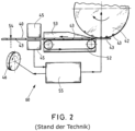
- In 2 60 is another embodiment of a filter rod machine according to FIG EP 2 243 385 A2 shown schematically. Accordingly, the components insert wheel 42, microwave resonator 45 and the cutting device 46 are also shown.
- the insert wheel 42 has troughs into which only one capsule 43 is introduced in this exemplary embodiment. This is in contrast to the embodiment according to 1 , In each of which double depressions are provided, in which the two different or identical capsules are inserted one behind the other. The capsules are held in line 40 by suction air until they are transferred.
- a format device 53 is shown, which has a format tape 52, among other things.
- a format device is also in the embodiment according to FIG 1 available, but not shown there.
- the position control takes place as a function of a measured position value of the respectively inserted capsule 43 in the strand 40, which is generated by the microwave resonator 45 and is fed to a position controller 55.
- the position controller 55 controls or regulates the angular position of the insertion wheel 42 relative to the cutting device 46 so that the correct cutting position 54 can always be maintained, which is at a predetermined distance from the capsule 43 that has been introduced.
- FIG. 3 shows schematically and three-dimensionally a part of another known filter rod machine according to FIG EP 2 243 385 A2 .
- a two-rod machine is shown, ie a filter rod machine for processing two filter rods 40 and 40'.
- two insertion wheels 42, 42' are also provided, which are each driven by corresponding drive systems 47, 47'. In this case, too, the insertion wheels 42, 42' serve to insert capsules 43 into the filter rods 40, 40'.
- a bobbin is also shown, from which the covering material 62, 62' is pulled off after cutting.
- the wrapping material 62, 62' is fed to two format belts 52, 52'.
- the format tapes 52, 52' are driven by means of drive systems 64, 64'.
- the filter rods 40, 40' are placed on the format belts 52, 52' and guided through format devices 53, 53', in which the wrapping material strips 62, 62' are wound around the filter rods and also closed.
- a seam flattening device 63 in which the seams of the strip of wrapping material or the adhesive for sealing the seams are dried, in particular by the action of heat.
- the strands 40, 40' then pass through a microwave resonator 45', which has two passage openings for the strands 40, 40'.
- the microwave resonator 45' can be a microwave measuring device that consists of two microwave resonators that are decoupled from one another in order to enable very good measurement accuracy for the respective strand.
- microwave resonator 45 After the microwave resonator 45 or the microwave resonator device, there are two cutting devices 46, 46', which are each driven by drive systems 49 and 49'.
- the position control of the corresponding driven components namely the insertion wheels 42, 42', the format tapes 52 and 52' and the cutting device 46 and 46', is controlled via corresponding drive systems 47, 47'; 64, 64' and 49, 49'.
- the position control of the format tapes 52 and 52' includes a superimposed speed control.
- the position controller 48 receives the position of the respective capsules 43 in the respective strands from the microwave resonator 45'. This situation is further processed into control variables that are used to control the drive systems. In this way, the position, in particular the angular position, of the cutting devices 46, 46' can be regulated or controlled. Correspondingly, the angular position of the cutting devices 46, 46' relative to the speed or speeds of the format belts 52 and 52' can also be controlled or regulated. Finally, it is possible to control or regulate the angular position of the insertion wheels 42, 42' relative to the speed of the format tapes 52 and 52'.
- the position of the capsules 43 introduced into the filter rods 40, 40' is controlled or regulated in such a way that the capsules are always at the same distance in the conveying direction of the rods 40, 40' lie parallel in the two strands 40, 40'.
- the cutting devices 46 and 46' can cut the strands at the same time, and the run of the filter strands 40, 40' and the further processing of the cut-to-length filters are synchronized.
- a common cutting device can also be provided for both strands.
- a filter train 40 into which an insert wheel 42 inserts liquid-filled capsules 43, which it receives from a filling chute (no reference number), is conveyed towards an input of a microwave resonator, shown schematically.
- a microwave resonator shown schematically.
- a cylindrical resonator for example, according to DE 198 54 550 B4 arranged, which the filter train 40 passes through centrally.
- FIGs 5a) and 5b shows the case in which a capsule 43 is not arranged centrally in a section of a filter rod or in a cylindrical filter rod 10.
- this situation is shown in perspective, with a central target position being shown as the zero point of a Cartesian coordinate system, one axis of which runs through the central axis of symmetry of the cylindrical object and the other two perpendicular to it.
- An offset of the capsule 43 is in Figure 5a ) already recognizable.
- Figure 5b is a plan view of an end face of the filter rod 10 showing that the capsule 43 is highly eccentric and does not even touch the target position 12. Such incorrect positioning should lead to the exclusion of the filter rod 10 from further production.
- FIG DE 198 54 550 B4 represents the characteristics of the resonant microwave field in a hollow cylindrical microwave resonator 45 as shown in FIG DE 198 54 550 B4 is known. This is operated in the E 010 mode, so that the greatest field strength is in the centre.
- the solid straight arrows mean the E field lines (electric field lines) and the closed dashed field lines mean the (magnetic) H field lines.
- an open coaxial resonator 30 shown in detail schematically in cross section.
- the open coaxial resonator 30 is cylindrical in cross section and has a bottom 33 and a central conductor 34 .
- the end face opposite the bottom 33 is open with an opening 35 from which a microwave measuring field 32 exits, which is particularly strongly bundled at the point where the central conductor 35 exits.
- the strength of the microwave measuring field 32 decreases greatly as the distance from the opening 35 increases.
- a filter rod 10 or a filter rod with a capsule 43 is located just centrally above the opening 35 of the coaxial resonator 30 and thus the microwave field 32 is maximally influenced by the presence of the capsule 43 filled with liquid.
- In 8 shows the frequency curve of the amplitude A of the resonant microwave field 32 in the resonator.
- the resonance curve 36 represents the case without the capsule present.
- the resonance curve 36' shows the case with the capsule 43 present. It can be seen that the resonance maximum is shifted by a resonance shift, which is marked with a double arrow, and at lower frequencies the resonance curve 36 'is above the resonance curve 36.
- the measurement frequency 39 actually used is on the lower edge of the resonance curves 36, 36'.
- the resonant frequency and the damping and quality change accordingly in the excited oscillating system 8 are changed in the microwave field, the resonant frequency and the damping and quality change accordingly in the excited oscillating system 8 .
- Both variables can be determined and evaluated in the same way as in the previous system, for example by means of the power loss amplitude and the first derivation at a fixed measurement frequency.
- a transmission measurement S 21 or a reflection measurement S 11 can be used.
- a measurement according to the resonance sequence method, which is constructed in particular as a reflection measurement, is also possible according to the invention.
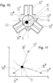
- FIG. 10 shows a cross-sectional representation of a star-shaped arrangement according to the invention of three open coaxial resonators 30 I-III , which are arranged around a filter rod 10 .
- the arrangement also applies in the same way in the event that instead of a filter rod 10 an endless filter rod 40 with capsules 43 is checked.
- the three microwave resonators 30 I-III are aligned with their respective openings towards the filter rod 10 and are arranged at angles of 120° to one another, ie they form an equilateral triangle. How out 10 can also be seen, the microwave measuring fields 32 I-III partially overlap one another. Therefore, different measurement frequencies are used to decouple them from each other.
- the object 43 is arranged highly eccentrically, as away from the central target position 12 and offset to the edge 11 of the filter rod 10 .
- the capsule 43 is thus located close to the entrance of the coaxial resonator 30 III and has a very strong influence on the microwave field 32 III .
- it is about the same distance from the side openings of the coaxial resonators 30 I and 30 ", so that their microwave fields 32 I and 32 II experience only comparatively weak changes.
- the result is a strong measurement signal for the open coaxial resonator 30 III and weak measurement signals for the coaxial resonators 30 I and 30 II .
- In 11 is a triangulation from the measurement results according to 10 represented graphically.
- crosses 31 I-III are the positions of the open coaxial resonators 30 I-III according to 10 designated.
- the lines emanating from the crosses have a length corresponding to a weighted measured respective distance 38 I-III . Since the measurement signals also depend on the filling level of the capsule 43 in addition to the respective distance, a corresponding weighting must be carried out.
- the various measurement signals first allow an assessment of the relative distances between the capsule 43 and the three microwave resonators 30 I-III in the form that the ratios of the distances are known, but not the absolute values. Then the distances are varied with the determined fixed distance ratios until the corresponding circles (cf. dashed lines in 11 ) intersect with the corresponding distances around positions 31 I-III at a common intersection. The point of intersection marks the transverse actual position 13 of the capsule 43. When the actual position 13 of the capsule 43 is known, conclusions can then be drawn from the measurement signals as to its filling state. For this purpose, the measurement signals are added up, for example weighted by distance, with the anisotropy of the emerging microwave measurement fields having to be taken into account.
- the longitudinal position in the strand or article can also be determined via the running direction and the time component of the measurement signal, for example according to the maximum degree of filling determined as a function of the current strand or article position. It can also be used to determine whether capsules or objects are missing or duplicated in places where an object should have been inserted.
Landscapes
- Physics & Mathematics (AREA)
- General Health & Medical Sciences (AREA)
- Health & Medical Sciences (AREA)
- Biochemistry (AREA)
- Chemical & Material Sciences (AREA)
- Analytical Chemistry (AREA)
- Life Sciences & Earth Sciences (AREA)
- Electromagnetism (AREA)
- General Physics & Mathematics (AREA)
- Immunology (AREA)
- Pathology (AREA)
- Toxicology (AREA)
- Manufacturing Of Cigar And Cigarette Tobacco (AREA)
Description
Die Erfindung betrifft eine Messvorrichtung zur Überprüfung wenigstens eines längsaxial geförderten stabförmigen Artikels oder Materialstrangs der Tabak verarbeitenden Industrie zur Überprüfung einer Position wenigstens eines in den Artikel oder den Materialstrang eingelegten Objekts, insbesondere einer flüssigkeitsgefüllten Kapsel, mittels wenigstens eines Mikrowellenmessfeldes, eine Verwendung sowie eine Maschine der Tabak verarbeitenden Industrie. Die Erfindung betrifft weiter ein Verfahren zur Überprüfung wenigstens eines längsaxial geförderten stabförmigen Artikels oder Materialstrangs der Tabak verarbeitenden Industrie, in den wenigstens ein Objekt, insbesondere eine flüssigkeitsgefüllte Kapsel, eingelegt ist, mittels wenigstens eines Mikrowellenmessfeldes.The invention relates to a measuring device for checking at least one rod-shaped article or strand of material conveyed along the longitudinal axis in the tobacco processing industry for checking the position of at least one object inserted into the article or the strand of material, in particular a liquid-filled capsule, by means of at least one microwave measuring field, a use and a machine for tobacco processing industry. The invention further relates to a method for checking at least one rod-shaped article or strand of material conveyed along the longitudinal axis of the tobacco processing industry, in which at least one object, in particular a liquid-filled capsule, is inserted, by means of at least one microwave measuring field.
Die Erfindung betrifft somit die Herstellung eines objektbefüllten Filterstrangs für stabförmige Artikel der Tabak verarbeitenden Industrie, insbesondere für Filterzigaretten. Der Filterstrang wird nach seiner Herstellung in einzelne Filterstäbe abgelängt. Der Filterstrang bzw. die abgelängten Filterstäbe enthalten als wesentlichen Bestandteil ein oder mehrere Objekte, die die Rauch- oder Filtereigenschaften beeinflussen.The invention thus relates to the production of an object-filled filter rod for rod-shaped articles in the tobacco processing industry, in particular for filter cigarettes. After manufacture, the filter strand is cut into individual filter rods. The filter strand or the cut-to-length filter rods contain one or more objects that influence the smoke or filter properties as an essential component.
Bei den Objekten handelt es sich insbesondere um Kapseln mit einer festen Hülle, die mit einer Flüssigkeit gefüllt sind. Die Flüssigkeit enthält in solchen Fällen üblicherweise Geschmacksstoffe oder Duftstoffe, beispielsweise Menthol. Zur Verwendung bricht ein Raucher die Kapsel vor dem Rauchen durch Druck auf den Filter auf und zündet die Zigarette anschließend an. Durch den Druck auf die Kapsel im Filter wird die Flüssigkeit freigesetzt, so dass sich das Aroma der Flüssigkeit entfaltet. Diese Vorgehensweise bietet ein besonders intensives oder frisches Geschmackserlebnis. Entsprechende Kapseln weisen üblicherweise einen Durchmesser von ca. 3,5 mm auf, können aber auch kleiner oder größer sein.The objects are, in particular, capsules with a solid shell that are filled with a liquid. In such cases, the liquid usually contains flavorings or fragrances, for example menthol. To use, a smoker breaks open the capsule before smoking by pressing on the filter and then lights the cigarette. The pressure on the capsule in the filter releases the liquid so that the aroma of the liquid unfolds. This procedure offers a particularly intense or fresh taste experience. Corresponding capsules usually have a diameter of approx. 3.5 mm, but can also be smaller or larger.
In der
Aus
Demgegenüber liegt der vorliegenden Erfindung die Aufgabe zugrunde, eine Messvorrichtung und ein Verfahren zur Verfügung zu stellen, mit denen eine weiter verbesserte Überprüfung von objektbeladenen Filtersträngen oder stabförmigen Artikeln der Tabak verarbeitenden Industrie möglich ist.In contrast, the object of the present invention is to provide a measuring device and a method with which a further improved inspection of object-loaded filter rods or rod-shaped articles in the tobacco processing industry is possible.
Diese Aufgabe wird durch eine Messvorrichtung zur Überprüfung wenigstens eines längsaxial geförderten stabförmigen Artikels oder Materialstrangs der Tabak verarbeitenden Industrie gelöst, insbesondere zur Überprüfung einer Position wenigstens eines in den Artikel oder den Materialstrang eingelegten Objekts, insbesondere einer flüssigkeitsgefüllten Kapsel, mittels wenigstens eines Mikrowellenmessfeldes, das dadurch weitergebildet ist, dass wenigstens zwei, insbesondere wenigstens drei, Mikrowellenresonatoren mit seitlichen Öffnungen an in Umfangsrichtung des Artikels oder Materialstrangs unterschiedlichen Positionen um den Artikel oder den Materialstrang herum angeordnet sind und den Artikel oder Materialstrang jeweils von einer Seite mit einem Mikrowellenmessfeld beaufschlagen, wobei die wenigstens zwei Mikrowellenresonatoren als offene Koaxialresonatoren ausgebildet sind, wobei die offene Seite des Koaxialresonators zum Artikel oder Materialstrang hin ausgerichtet ist, wobei eine mit den Mikrowellenresonatoren verbundene Leistungselektronik ausgebildet ist, die Mikrowellenresonatoren mit unterschiedlichen Mikrowellenmessfrequenzen zu beaufschlagen.This object is achieved by a measuring device for checking at least one rod-shaped article or strand of material conveyed along the longitudinal axis in the tobacco processing industry, in particular for checking the position of at least one object inserted into the article or the strand of material, in particular a liquid-filled capsule, by means of at least one microwave measuring field, which is further developed that at least two, in particular at least three, microwave resonators with lateral openings are arranged at different positions around the article or material strand in the circumferential direction of the article or material strand and impinge on the article or material strand from one side with a microwave measuring field, wherein the at least two microwave resonators are designed as open coaxial resonators, the open side of the coaxial resonator being oriented towards the article or material strand, power electronics connected to the microwave resonators being designed to apply different microwave measurement frequencies to the microwave resonators.
Damit wird die Problematik gelöst, dass bei Zigarettenstrangmaschinen oder Filterstrangmaschinen mit Objekt- oder Kapseleinlegevorrichtungen sich die Objekte bzw. Kapseln verfahrensbedingt nicht immer mittig im Querschnitt des Materialstrangs einlegen lassen, so dass diese in einigen Fällen in Richtung des Randes des Filterstrangs eingebettet werden. In extremen Fällen befindet sich dann im Falle eines Filterstrangs überhaupt kein Acetat mehr zwischen Kapsel und Filterpapier. Die Kapsel ist dann direkt unter dem Filterpapier sichtbar und fühlbar. Diese ungewollte Verlagerung bewirkt, dass Kapseln in späteren Verfahrensschritten häufiger beschädigt werden und auslaufen, da sie nicht von allen Seiten gleichmäßig durch das Filtermaterial geschützt und daher empfindlicher gegenüber Krafteinflüssen sind, wie sie zum Beispiel in Logistikkomponenten, auf den Trommeln einer Filteransetzmaschine oder während des Verpackens auftreten. Soweit die Erfindung nachfolgend am Beispiel eines mit Objekten belegten Filterstrangs erläutert wird, gelten die Ausführungen entsprechend auch für mit Objekten belegte umhüllte Tabakstränge und Zigarettenstränge.This solves the problem that in cigarette rod machines or filter rod machines with object or capsule insertion devices, the process causes the objects or capsules not always to be inserted in the middle of the cross section of the material rod, so that in some cases they are embedded in the direction of the edge of the filter rod. In extreme cases, in the case of a filter rod, there is no longer any acetate between the capsule and the filter paper. The capsule can then be seen and felt directly under the filter paper. This unintentional displacement causes capsules to be damaged and leak more frequently in later process steps, since they are not evenly protected by the filter material on all sides and are therefore more sensitive to the influence of forces, such as those in logistics components, on the drums of a filter attachment machine or during packaging appear. Insofar as the invention is explained below using the example of a filter rod covered with objects, the explanations also apply accordingly to wrapped tobacco rods and cigarette rods covered with objects.
Zusätzlich ist das zentrische Platzieren mit qualitativen Anforderungen an die Zigarette verbunden. So ist es notwendig, damit sich die Flüssigkeit der Kapseln bei allen Filtern gleich verteilt und sich das Brechen der Kapsel bei allen Zigaretten gleich anfühlt. Diese exzentrische Anordnung war mit den bisher verwendeten Mikrowellenmessvorrichtungen gemäß
Demgegenüber wird erfindungsgemäß nunmehr eine seitliche Beaufschlagung des längsaxial geförderten Strangs bzw. Artikels vorschlagen. Bei einer seitlichen, also radialen, Beaufschlagung ist die Stärke jedes einzelnen Mikrowellenfeldes in radialer Richtung des Strangs bzw. Artikels stark anisotrop, so dass eine exzentrische Anordnung der Objekte, beispielsweise Kapseln, sich in einer asymmetrischen Signalantwort bezüglich der unterschiedlich platzierten seitlichen Mikrowellenresonatoren äußert. Diese lässt sich zur Positionsbestimmung und zum Ausschluss von nicht regelkonformen Artikeln bzw. Filterstrangabschnitten oder umhüllten Tabakstrangabschnitten verwenden.In contrast, according to the invention, lateral loading of the strand or article conveyed along the longitudinal axis is now proposed. In the case of a lateral, i.e. radial, impact, the strength of each individual microwave field is highly anisotropic in the radial direction of the strand or article, so that an eccentric arrangement of the objects, for example capsules, is expressed in an asymmetrical signal response with regard to the differently placed lateral microwave resonators. This can be used to determine the position and to exclude non-compliant articles or filter rod sections or wrapped tobacco rod sections.
Die Messvorrichtung umfasst wenigstens zwei Mikrowellenresonatoren, die als offene Koaxialresonatoren ausgebildet sind. Diese sogenannten "Open Coaxial Surface Wave" Mikrowellenresonatoren sind zylindrisch aufgebaut mit einem zentralen Leiter. Über ein oder zwei Einkopplungsgeometrien, beispielsweise Antennen oder Lochplatten, wird magnetisch oder elektrisch das Mikrowellenfeld im Resonatorraum eingekoppelt. Eine Endfläche ist geschlossen, die Endfläche an der gegenüberliegenden Seite des Resonators ist offen. Aus der offenen Seite dringt ein Mikrowellenfeld nach außen, das mit zunehmender Entfernung stark nachlässt, also stark anisotrop ist. Die Signalantwort auf eine vorbeigeförderte Kapsel ist dabei einerseits stark vom Füllungszustand der Kapsel mit einem mikrowellenabsorbierenden Medium, beispielsweise einer wässrigen Geschmacksstofflösung, und andererseits vom Abstand der Kapsel von der offenen Endfläche, abhängig. Damit eignen sich Koaxialresonatoren besonders gut für den erfindungsgemäßen Einsatz.The measuring device includes at least two microwave resonators, which are designed as open coaxial resonators. These so-called "Open Coaxial Surface Wave" microwave resonators are constructed cylindrically with a central conductor. The microwave field is coupled magnetically or electrically into the resonator chamber via one or two coupling geometries, for example antennas or perforated plates. One end face is closed, the end face on the opposite side of the resonator is open. A microwave field protrudes from the open side, which decreases greatly with increasing distance, i.e. it is strongly anisotropic. The signal response to a capsule conveyed past is strongly dependent on the filling state of the capsule with a microwave-absorbing medium, for example an aqueous flavoring solution, and on the distance of the capsule from the open end surface. Coaxial resonators are therefore particularly well suited for use according to the invention.
In einer bevorzugten Ausgestaltung sind drei Mikrowellenresonatoren in einer gleichwinkligen, insbesondere sternförmigen, Anordnung um den Artikel oder Materialstrang herum angeordnet. Diese einfache geometrische Anordnung erlaubt eine sichere und schnelle Positionsbestimmung, zusätzlich zu einer Füllstandsinformation für die Kapseln, die die Resonatorantwort als sogenannte "High-Loss"-Objekte maßgeblich bestimmen.In a preferred embodiment, three microwave resonators are arranged in an equiangular, in particular star-shaped, arrangement around the article or strand of material. This simple geometrical arrangement allows a safe and fast position determination, in addition to fill level information for the capsules, which decisively determine the resonator response as so-called "high-loss" objects.
Alternativ sind zwei Mikrowellenresonatoren vorgesehen, die um den Materialstrang, insbesondere Filterstrang oder Tabakstrang, herum angeordnet sind, insbesondere im Wesentlichen in einer Ebene quer zur Förderrichtung des Materialstrangs in einem Winkel von 60° bis 300° zueinander, insbesondere 180°. Im Falle des Winkels von 180° liegen sich die Mikrowellenresonatoren direkt gegenüber. Diese Anordnungen mit zwei Mikrowellenresonatoren kommen vorteilhaft zur Anwendung im Fall von Platz-, Raum- und/oder Kostenrestriktionen, wobei der Verlust an Information gegenüber Anordnungen mit drei oder mehr Mikrowellenresonatoren zu etwas weniger genauen Messergebnissen führen kann, insbesondere in Bezug auf die Erkennung der Kapselposition.Alternatively, two microwave resonators are provided, which are arranged around the material rod, in particular filter rod or tobacco rod, in particular essentially in a plane transverse to the conveying direction of the material rod at an angle of 60° to 300° to one another, in particular 180°. In the case of an angle of 180°, the microwave resonators are directly opposite one another. These arrangements with two microwave resonators are advantageously used in the case of space, space and/or cost restrictions, where the loss of information compared to arrangements with three or more microwave resonators can lead to somewhat less accurate measurement results, in particular with regard to the detection of the capsule position .
Erfindungsgemäß werden die wenigstens zwei Mikrowellenresonatoren mit unterschiedlichen Frequenzen betrieben. Vorzugsweise werden die Mikrowellenresonatoren mit Mikrowellenmessfrequenzen zwischen 1 GHz und 10 GHz, insbesondere zwischen 4 GHz und 7 GHz, beaufschlagt.According to the invention, the at least two microwave resonators are operated at different frequencies. The microwave resonators are preferably subjected to microwave measuring frequencies between 1 GHz and 10 GHz, in particular between 4 GHz and 7 GHz.
Besonders für den Fall unterschiedlicher Messfrequenzen für die verschiedenen Mikrowellenresonatoren ist vorteilhafterweise vorgesehen, dass die Mikrowellenresonatoren, insbesondere offene Koaxialresonatoren, für verschiedene Mikrowellenmessfrequenzen unterschiedliche Längen und/oder Formen bei gleichem Durchmesser aufweisen. Die Längen und/oder Formen sind an die gewünschten Messfrequenzen angepasst, während der gleich gewählte Durchmesser sicherstellt, dass die Geometrie des aus dem jeweiligen Mikrowellenresonator seitlich austretenden Mikrowellenmessfeldes zumindest annähernd gleich ist, um eine geometrisch in Bezug auf die Interaktion von Objekt mit Mikrowellenmessfeld gleichartige Messung zu gewährleisten. Bei verschiedenen Frequenzen ändert sich die Eindringtiefe eines Mikrowellenfeldes, so dass Mikrowellenmessfelder unterschiedlicher Frequenzen unter Materialbeladung nicht identisch, aber annähernd gleich sein werden.Particularly in the case of different measurement frequencies for the different microwave resonators, it is advantageously provided that the microwave resonators, in particular open coaxial resonators, have different lengths and/or shapes for different microwave measurement frequencies with the same diameter. The lengths and/or shapes are adapted to the desired measurement frequencies, while the diameter chosen to be the same ensures that the geometry of the microwave measurement field emerging laterally from the respective microwave resonator is at least approximately the same in order to obtain a measurement that is geometrically similar in terms of the interaction of the object with the microwave measurement field to ensure. The penetration depth of a microwave field changes at different frequencies, so that microwave measuring fields of different frequencies under material loading will not be identical, but will be approximately the same.
Um zu gewährleisten, dass sich der Abstand zwischen dem Filterstrang oder den stabförmigen Artikeln und den Mikrowellenresonatoren im Laufe einer Produktion nicht ändert und somit systematische Abweichungen in den Messungen auftreten, ist vorzugsweise vorgesehen, dass eine Führungsvorrichtung zur Führung des Artikels oder des Materialstrangs im Bereich der Mikrowellenresonatoren vorgesehen ist, mittels der ein Abstand zwischen dem Artikel oder Materialstrang und den Öffnungen der Mikrowellenresonatoren vorgebbar ist. Eine solche Führungsvorrichtung kann beispielsweise ein Kunststoffrohr aus einem für Mikrowellen im Wesentlichen transparenten Material sein, beispielsweise PEEK (Polyetheretherketon).In order to ensure that the distance between the filter rod or the rod-shaped articles and the microwave resonators does not change in the course of production and thus systematic deviations in the measurements occur, it is preferably provided that a guide device for guiding the article or the material rod in the area of the Microwave resonators is provided, by means of which a distance between the article or strand of material and the openings of the microwave resonators can be specified. Such a guide device can be, for example, a plastic tube made of a material that is essentially transparent to microwaves, for example PEEK (polyetheretherketone).
Für verschiedene Formate können auch verschiedene Führungsvorrichtungen vorgesehen sein. So kann beispielsweise der Innendurchmesser eines Führungsrohrs zur Adaption eines neuen Filterstrangformats angepasst sein, während der Außendurchmesser konstant bleibt, um die Anordnung der Mikrowellenresonatoren fix zu halten. Alternativ können auch die Mikrowellenresonatoren in radialer Richtung beweglich, insbesondere miteinander gekoppelt, angebracht sein, so dass auf eine Verkleinerung oder Vergrößerung des Durchmessers beim Übergang von einem Filterstrangformat auf ein anderes durch Austausch des Führungsrohrs und Zusammenrücken oder Auseinanderrücken der Mikrowellenresonatoren reagiert werden kann.Different guide devices can also be provided for different formats. For example, the inner diameter of a guide tube can be adjusted to adapt a new filter rod format, while the outer diameter remains constant remains to keep the arrangement of the microwave resonators fixed. Alternatively, the microwave resonators can also be movably attached in the radial direction, in particular coupled to one another, so that a reduction or increase in the diameter when changing from one filter rod format to another can be reacted to by exchanging the guide tube and moving the microwave resonators together or apart.
Die der Erfindung zugrunde liegende Aufgabe wird auch durch eine Verwendung einer erfindungsgemäßen, zuvor beschriebenen Messvorrichtung zur Überprüfung wenigstens eines längsaxial geförderten stabförmigen Artikels oder Materialstrangs der Tabak verarbeitenden Industrie zur Überprüfung einer Position wenigstens eines in den Artikel oder den Materialstrang eingelegten Objekts gelöst, insbesondere einer flüssigkeitsgefüllten Kapsel, insbesondere einer transversalen Position des Objekts im Artikel oder Materialstrang und/oder eines radialen Abstands des Objekts von einem Mittelpunkt und/oder von einem Rand des Artikels oder Materialstrangs. Dabei sind im Rahmen der vorliegenden Erfindung unter einem Materialstrang alle Materialstränge der Tabak verarbeitenden Industrie zu verstehen, unter anderem Zigarettenstränge, umhüllte Tabakstränge, Monoacetat, Kammer- und Multisegmentfilterstränge.The object on which the invention is based is also achieved by using a measuring device according to the invention, described above, for checking at least one rod-shaped article or strand of material conveyed along the longitudinal axis of the tobacco processing industry for checking the position of at least one object placed in the article or the strand of material, in particular an object filled with liquid Capsule, in particular a transverse position of the object in the article or strand of material and/or a radial distance of the object from a center point and/or from an edge of the article or strand of material. Within the scope of the present invention, a material rod is to be understood as meaning all material rods in the tobacco processing industry, including cigarette rods, wrapped tobacco rods, monoacetate, chamber and multi-segment filter rods.
Ebenfalls wird die der Erfindung zugrunde liegende Aufgabe durch eine Maschine der Tabak verarbeitenden Industrie, insbesondere Filterstrangmaschine oder Zigarettenstrangmaschine, mit wenigstens einer erfindungsgemäßen, zuvor beschriebenen Messvorrichtung zur Überprüfung von längsaxial geförderten Artikeln oder ein oder zwei Materialsträngen, insbesondere Filtersträngen oder umhüllten Tabaksträngen oder Zigarettensträngen, gelöst.The object on which the invention is based is also achieved by a machine in the tobacco processing industry, in particular a filter rod machine or cigarette rod machine, with at least one measuring device according to the invention and described above for checking longitudinally axially conveyed articles or one or two material rods, in particular filter rods or wrapped tobacco rods or cigarette rods .
Schließlich wird diese Aufgabe durch ein Verfahren zur Überprüfung wenigstens eines längsaxial geförderten stabförmigen Artikels oder Materialstrangs der Tabak verarbeitenden Industrie, in den wenigstens ein Objekt, insbesondere eine flüssigkeitsgefüllte Kapsel, eingelegt ist, mittels wenigstens eines Mikrowellenmessfeldes, gelöst, in einer erfindungsgemäßen, zuvor beschriebenen Messvorrichtung, das dadurch weitergebildet ist, dass der Artikel oder der Materialstrang während einer längsaxialen Förderung von drei in Umfangsrichtung unterschiedlichen Seiten mit jeweils einem von einer Seite radial eindringenden Mikrowellenmessfeld aus jeweils wenigstens einem seitlich offenen Mikrowellenresonator beaufschlagt wird, wobei aus den aus der Anwesenheit eines in den Artikel oder Materialstrang eingelegten Objekts resultierenden Änderungen der jeweiligen Messsignale der drei Mikrowellenresonatoren wenigstens eine Eigenschaft des Objekts ermittelt wird, wobei die drei Mikrowellenresonatoren als offene Koaxialresonatoren ausgebildet sind, wobei die offene Seite des Koaxialresonators zum Artikel oder Materialstrang hin ausgerichtet ist, wobei eine ermittelte Eigenschaft eine transversale Position des Objekts im Artikel oder Materialstrang und/oder ein radialer Abstand des Objekts von einem Mittelpunkt und/oder von einem Rand des Artikels oder Materialstrangs ist. Alternativ oder zusätzlich dazu ist vorteilhafterweise eine ermittelte Eigenschaft eine längsaxiale Position des Objekts im Artikel oder Materialstrang.Finally, this object is achieved by a method for checking at least one longitudinally axially conveyed rod-shaped article or material strand of the tobacco processing industry, in which at least one object, in particular a liquid-filled capsule, is inserted, by means of at least one microwave measuring field, in a measuring device according to the invention and described above , which is further developed in that the article or the strand of material is acted upon during a longitudinal-axial conveyance from three different sides in the circumferential direction, each with a microwave measuring field penetrating radially from one side and consisting of at least one microwave resonator open at the side, whereby from the presence of a microwave resonator in the At least one property of the object is determined as a result of changes in the respective measurement signals of the three microwave resonators inserted in the object or strand of material, with the three microwave resonators being designed as open coaxial resonators, with the open side of the coaxial resonator being oriented towards the article or strand of material, with one property determined having a transverse position of the object in the article or strand of material and/or a radial distance of the object from a center point and/or from an edge of the article or strand of material. As an alternative or in addition to this, a determined property is advantageously a longitudinal-axial position of the object in the article or strand of material.
Damit wird bei dem erfindungsgemäßen Verfahren die Aufgabe mit gleichartigen Mitteln gelöst wie bei der erfindungsgemäßen Messvorrichtung.With the method according to the invention, the object is thus achieved with the same type of means as with the measuring device according to the invention.
Schließlich ist es alternativ oder zusätzlich vorteilhaft, wenn eine ermittelte Eigenschaft eine Füllmenge, ein Füllungsgrad, ein Beschädigungszustand und/oder ein Fehlen eines Objekts ist oder ein Überschuss an eingelegten Objekten an einer längsaxialen Position im Artikel oder Materialstrang.Finally, it is alternatively or additionally advantageous if a determined property is a filling quantity, a filling level, a state of damage and/or a missing object or an excess of objects inserted at a longitudinal axial position in the article or material strand.
Die Ermittlung erfolgt bevorzugt und besonders einfach mittels einer Triangulation und/oder einer Look-Up-Tabelle, die insbesondere simulativ oder empirisch bestimmt ist oder wird. Eine Look-Up-Tabelle enthält vorbestimmte oder vorberechnete Werte zu den zu ermittelnden Größen in Abhängigkeit der direkten Messgrößen. Es handelt sich somit um eine mehrdimensionale Tabelle mit Werte-Tupeln. Die Triangulation verwendet die relativen Unterschiede zwischen den Messsignalen der Mikrowellenresonatoren, um den Abstand des Objekts von den jeweiligen Mikrowellenresonatoren zu ermitteln. Anschließend wird anhand der bekannten Positionen der Mikrowellenresonatoren und der jeweiligen dazu ermittelten Abstände der Schnittpunkt der Kreise bestimmt, die dem jeweiligen Abstand von der seitlichen Öffnung des jeweiligen Mikrowellenresonators entsprechen. Die so triangulierte Position entspricht der transversalen bzw. exzentrischen Position des Objekts bzw. der Kapsel im Materialstrang oder beispielsweise in einem Filterstrang oder einem umhüllten Tabakstrang im stabförmigen Artikel, beispielsweise Filterstab oder Filterzigarette.The determination is preferably and particularly easily carried out by means of a triangulation and/or a look-up table, which is or will be determined, in particular, simulatively or empirically. A look-up table contains predetermined or pre-calculated values for the variables to be determined depending on the direct measured variables. It is therefore a multidimensional table with value tuples. The triangulation uses the relative differences between the measurement signals of the microwave resonators to determine the distance of the object from the respective microwave resonators. The point of intersection of the circles, which correspond to the respective distance from the lateral opening of the respective microwave resonator, is then determined on the basis of the known positions of the microwave resonators and the respective distances determined thereto. The position triangulated in this way corresponds to the transversal or eccentric position of the object or the capsule in the material rod or, for example, in a filter rod or a wrapped tobacco rod in a rod-shaped article, for example a filter rod or filter cigarette.
In einer bevorzugten Weiterbildung wird ein Artikel oder ein Abschnitt des Materialstrangs, der ein Objekt enthält, das wenigstens einen vorbestimmten oder vorbestimmbaren Grenzwert für die wenigstens eine ermittelte Eigenschaft nicht einhält, von der weiteren Verarbeitung ausgeschlossen und/oder aus dem Herstellungsprozess ausgeschleust. Dies erfolgt insbesondere durch Ausblasen.In a preferred development, an article or a section of the strand of material that contains an object that does not comply with at least one predetermined or predeterminable limit value for the at least one determined property is excluded from further processing and/or ejected from the manufacturing process. This is done in particular by blowing out.
Das erfindungsgemäße Verfahren wird vorzugsweise in einem selbstlernenden System eingesetzt, wobei Grenzwerte für ordnungsgemäße Füllobjekte, beispielsweise Kapseln, für jede Produktion angepasst werden. So können vorzugsweise anhand beispielsweise der ersten 10 bis 50 Kapseln im Strang oder in Artikeln zunächst erste Bereiche für Grenzwerte festgelegt werden und anschließend ein laufendes Mittel über beispielsweise 500 bis 1000 Objekte im Materialstrang bzw. in Artikeln verwendet werden, um die Grenzwerte laufend anzupassen. Damit kann normalen Variationen in der Produktion Rechnung getragen werden, ohne die Fähigkeit einzubüßen, tatsächlich fehlerhafte oder fehlerhaft positionierte Objekte zu erkennen und entsprechende Strangabschnitte oder Filterstäbe zu entfernen. Auch die Kalibrierung der Messung bzw. der Messvorrichtungen kann entsprechend selbstlernend ausgestaltet sein.The method according to the invention is preferably used in a self-learning system, with limit values for correct filling objects, for example capsules, being adjusted for each production. For example, the first 10 to 50 capsules in the strand or in articles can be used to initially determine first ranges for limit values and then a running average of, for example, 500 to 1000 objects in the material strand or in articles can be used to continuously adjust the limit values. This allows for normal variations in production to be accommodated without sacrificing the ability to identify actual defects or errors to recognize positioned objects and to remove corresponding strand sections or filter rods. The calibration of the measurement or the measuring devices can also be designed to be self-learning.
Die zu den einzelnen Erfindungsgegenständen, also der Messvorrichtung, der Maschine, der Verwendung und dem Verfahren, genannten Merkmale, Vorteile und Eigenschaften gelten ohne Einschränkung auch für die aufeinander bezogenen anderen Erfindungsgegenstände, die den gleichen Erfindungsgedanken mit gleichartigen, einander entsprechenden Mitteln verwirklichen.The features, advantages and properties mentioned for the individual objects of the invention, i.e. the measuring device, the machine, the use and the method, also apply without restriction to the other objects of the invention which relate to one another and which implement the same inventive idea with similar, corresponding means.
Weitere Merkmale der Erfindung werden aus der Beschreibung erfindungsgemäßer Ausführungsformen zusammen mit den Ansprüchen und den beigefügten Zeichnungen ersichtlich. Erfindungsgemäße Ausführungsformen können einzelne Merkmale oder eine Kombination mehrerer Merkmale erfüllen.Further features of the invention will be apparent from the description of embodiments of the invention taken together with the claims and the accompanying drawings. Embodiments according to the invention can fulfill individual features or a combination of several features.
Die Erfindung wird nachstehend ohne Beschränkung des allgemeinen Erfindungsgedankens anhand von Ausführungsbeispielen unter Bezugnahme auf die Zeichnungen beschrieben, wobei bezüglich aller im Text nicht näher erläuterten erfindungsgemäßen Einzelheiten ausdrücklich auf die Zeichnungen verwiesen wird. Es zeigen:
- Fig. 1
- eine schematische Darstellung eines Teils einer bekannten Filterstrangmaschine,
- Fig. 2
- eine schematische Darstellung eines Teils einer weiteren bekannten Filterstrangmaschine,
- Fig. 3
- eine schematische dreidimensionale Darstellung eines Teils einer weiteren bekannten Filterstrangmaschine,
- Fig. 4
- eine perspektivische Darstellung einer bekannten Messanordnung,
- Fig. 5a), b)
- schematische Darstellungen einer Anordnung eines Objekts in einem stabförmigen Artikel,
- Fig. 6a), b)
- schematische Darstellungen eines bekannten Mikrowellenresonatorfelds,
- Fig. 7
- eine schematische Darstellung eines offenen Koaxialresonators mit einem objektbeladenen stabförmigen Artikel,
- Fig. 8
- ein Resonanzkurven-Diagramm,
- Fig. 9
- einen typischen Signalverlauf,
- Fig. 10
- eine Querschnittsdarstellung durch eine erfindungsgemäße Messanordnung und
- Fig. 11
- eine diagrammatische Darstellung einer Objektpositionsbestimmung.
- 1
- a schematic representation of part of a known filter rod machine,
- 2
- a schematic representation of part of another known filter rod machine,
- 3
- a schematic three-dimensional representation of a part of another known filter rod machine,
- 4
- a perspective view of a known measuring arrangement,
- Fig. 5a), b)
- schematic representations of an arrangement of an object in a rod-shaped article,
- Fig. 6a), b)
- schematic representations of a known microwave resonator field,
- 7
- a schematic representation of an open coaxial resonator with an object-loaded rod-shaped article,
- 8
- a resonance curve diagram,
- 9
- a typical signal course,
- 10
- a cross-sectional view through a measuring arrangement according to the invention and
- 11
- a diagrammatic representation of an object position determination.
In den Zeichnungen sind jeweils gleiche oder gleichartige Elemente und/oder Teile mit denselben Bezugsziffern versehen, so dass von einer erneuten Vorstellung jeweils abgesehen wird.In the drawings, elements and/or parts that are the same or of the same type are provided with the same reference numbers, so that they are not presented again in each case.
Der mit den Kapseln 43 und 44 befüllte Filterstrang 40 durchläuft dann einen Mikrowellenresonator 45, in dem unter anderem die Qualität des Filterstrangs und die Befüllung mit Kapseln 43 und 44 überprüft wird. Die Form des Mikrowellenresonators ist aus
Die Steuerung und Regelung der entsprechenden Komponenten der Filterstrangmaschine 60 wird im Folgenden dargestellt:
Die Drehgeschwindigkeit des Einlegerads 42 wird durch ein lagegeregeltes Antriebssystem 47 gesteuert. Dieses gibt ein entsprechendes Steuersignal an das Einlegerad bzw. den Aktuator des Einlegerads 42 ab. Die jeweilige Drehposition des Einlegerads wird als längsaxiale Istposition dem Antriebssystem 47 zurückgeführt, das einen Lageistwert einer Lageregelung 48 zur Verfügung stellt. Die Lageregelung 48 gibt einen Lagesollwert an das Antriebssystem 47 ab. Dieses ist durch die entsprechenden Striche mit Pfeilen, die die jeweiligen Komponenten in
The speed of rotation of the
Ferner gibt der Mikrowellenresonator 45 eine längsaxiale Istposition der in den Strang 40 eingelegten Kapseln 43 und 44 sowohl an die Lageregelung 48 als auch an ein Qualitätsüberwachungs- und Statistiksystem 50 weiter. Bei falscher Lage dient das Qualitätsüberwachungs- und Statistiksystem dazu, ein Auswurfsignal zur Ausblasvorrichtung 51 abzugeben, so dass entsprechende Filterstäbe 41 mit falsch positionierten Kapseln 43 bzw. 44 ausgeblasen werden.Furthermore, the
Außerdem gibt die Lageregelung 48 einen Lagesollwert an ein lagegeregeltes Antriebssystem 47 für das Einlegerad 42 ab. Der Lageistwert wird vom Antriebssystem 49 an die Lageregelung 48 zurückgeführt. Der Messerträger bzw. der Aktuator des Messerträgers 46 ist mit dem Antriebssystem 47 entsprechend verbunden.In addition, the
Bei idealer und fehlerfreier Produktion werden das Einlegerad 42 für die Kapseln 43, 44 sowie der Messerträger 46 in ihrer Winkellage einmal zueinander richtig eingestellt, so dass der Schnitt an der gewünschten Stelle relativ zu den Kapseln erfolgt. Durch Verschleiß eines Formatbandes, das beispielsweise auch in
In
Anschließend an das Einlegerad 42 ist in
Die Lageregelung geschieht in Abhängigkeit eines Positionsmesswertes der jeweils eingelegten Kapsel 43 in den Strang 40, der durch den Mikrowellenresonator 45 generiert wird und einem Lageregler 55 zugeführt wird. Der Lageregler 55 steuert bzw. regelt die Winkellage des Einlegerads 42 relativ zur Schneidvorrichtung 46, so dass immer die richtige Schnittposition 54 eingehalten werden kann, die in einem vorgegebenen Abstand zur eingebrachten Kapsel 43 liegt.The position control takes place as a function of a measured position value of the respectively inserted
Es ist zudem noch eine Bobine dargestellt, von der Umhüllungsmaterial 62, 62' nach einem Schneiden abgezogen wird. Das Umhüllungsmaterial 62, 62' wird zwei Formatbändern 52, 52' zugeführt. Die Formatbänder 52, 52' werden mittels Antriebssystemen 64, 64' angetrieben. Die Filterstränge 40, 40' werden auf die Formatbänder 52, 52' aufgelegt und durch Formatvorrichtungen 53, 53' geführt, in denen die Umhüllungsmaterialstreifen 62, 62' um die Filterstränge gewickelt werden und auch geschlossen werden.A bobbin is also shown, from which the covering
Es schließt sich eine Nahtplättvorrichtung 63 an, in der insbesondere durch Wärmeeinwirkung die Umhüllungsmaterialstreifennähte bzw. der Kleber zum Verschließen der Nähte getrocknet werden. Anschließend gelangen die Stränge 40, 40' durch einen Mikrowellenresonator 45', der zwei Durchtrittsöffnungen für die Stränge 40, 40' aufweist. Der Mikrowellenresonator 45' kann eine Mikrowellenmessvorrichtung sein, die aus zwei Mikrowellenresonatoren besteht, die voneinander entkoppelt sind, um eine sehr gute Messgenauigkeit für den jeweiligen Strang zu ermöglichen. Hierdurch kann dann bei dem jeweiligen Strang ein erfindungsgemäßes Verfahren zum Überwachen der Qualität der Beschickung eines Filters oder eines jeweiligen Filterstrangs der Tabak verarbeitenden Industrie mit Kapseln, die eine flüssige Füllung aufweisen, durchgeführt werden.This is followed by a
Nach dem Mikrowellenresonator 45 bzw. der Mikrowellenresonatorvorrichtung schließen sich zwei Schneidvorrichtungen 46, 46' an, die jeweils durch Antriebssysteme 49 und 49' angetrieben werden.After the
Die Lageregelung der entsprechenden angetriebenen Komponenten, nämlich der Einlegeräder 42, 42', der Formatbänder 52 und 52' als auch der Schneidvorrichtung 46 und 46', wird über entsprechende mit den Komponenten verbundene Antriebssysteme 47, 47'; 64, 64' und 49, 49' durchgeführt. Die Lageregelung der Formatbänder 52 und 52' umfasst dabei eine überlagerte Geschwindigkeitsregelung.The position control of the corresponding driven components, namely the
Die Lageregelung 48 erhält von dem Mikrowellenresonator 45' die Lage der jeweiligen Kapseln 43 in den jeweiligen Strängen. Diese Lage wird weiterverarbeitet zu Steuergrößen, die zur Ansteuerung der Antriebssysteme dienen. Auf diese Weise kann die Lage, insbesondere Winkellage, der Schneidvorrichtungen 46, 46' geregelt oder gesteuert werden. Entsprechend kann auch die Winkellage der Schneidvorrichtungen 46, 46' relativ zu der Geschwindigkeit oder den Geschwindigkeiten der Formatbänder 52 und 52' gesteuert oder geregelt werden. Schließlich ist es möglich, die Winkellage der Einlegeräder 42, 42' relativ zur Geschwindigkeit der Formatbänder 52 und 52' zu steuern oder zu regeln.The
Besonders bevorzugt ist es, wenn die Lage der in die Filterstränge 40, 40' eingebrachten Kapseln 43 so gesteuert bzw. geregelt wird, dass die Kapseln in Förderrichtung der Stränge 40, 40' immer im selben Abstand parallel in den beiden Strängen 40, 40' liegen. In diesem Fall können die Schneidvorrichtungen 46 und 46' zur gleichen Zeit die Stränge schneiden und es findet eine Synchronisation des Laufes der Filterstränge 40, 40' sowie der Weiterverarbeitung der abgelängten Filter statt. Auch kann für beide Stränge eine gemeinsame Schneidvorrichtung vorgesehen sein.It is particularly preferred if the position of the
In
In
In
In
Demgegenüber ist in
In
Werden in dem Mikrowellenfeld die Position und Lage einer Kapsel 43 relativ zur Resonatoroberfläche und an einem bestimmten Messpunkt verändert, verändern sich in dem angeregten schwingenden System die Resonanzfrequenz und die Dämpfung und Güte gemäß
In
Das Objekt 43 ist stark exzentrisch, als von der zentralen Sollposition 12 entfernt und an den Rand 11 des Filterstabs 10 versetzt, angeordnet. Damit befindet sich die Kapsel 43 nahe am Eingang des Koaxialresonators 30III und beeinflusst das Mikrowellenfeld 32III sehr stark. Zudem ist es etwa gleich weit von den seitlichen Öffnungen der Koaxialresonatoren 30I und 30" entfernt, so dass deren Mikrowellenfelder 32I und 32II nur vergleichsweise schwache Veränderungen erfahren. Das Ergebnis sind ein starkes Messsignal bei dem offenen Koaxialresonator 30III und schwache Messsignale bei den Koaxialresonatoren 30I und 30II.The
In
Die verschiedenen Messsignale erlauben zunächst eine Beurteilung der relativen Abstände der Kapsel 43 zu den drei Mikrowellenresonatoren 30I-III, in der Form, dass die Verhältnisse der Abstände bekannt sind, aber nicht die Absolutwerte. Dann werden die Abstände mit den ermittelten festen Abstandsverhältnissen so lange variiert, bis sich die entsprechenden Kreise (vgl. gestrichelte Linien in
Zusätzlich kann auch über die Laufrichtung und die zeitliche Komponente des Messsignals die Längsposition im Strang oder Artikel bestimmt werden, beispielsweise gemäß maximalem festgestelltem Füllungsgrad abhängig von der momentanen Strang- oder Artikelposition. Auch das Fehlen oder die Doppelung von Kapseln oder Objekten an Stellen, an denen ein Objekt eingelegt sein sollte, ist hiermit feststellbar ist.In addition, the longitudinal position in the strand or article can also be determined via the running direction and the time component of the measurement signal, for example according to the maximum degree of filling determined as a function of the current strand or article position. It can also be used to determine whether capsules or objects are missing or duplicated in places where an object should have been inserted.
- 1010
- Filterstabfilter rod
- 1111
- Rand des Filterstabsedge of the filter rod
- 1212
- Sollpositiontarget position
- 1313
- transversale Istpositiontransverse actual position
- 1414
- Führungsrohrguide tube
- 2020
- SenderChannel
- 2222
- EmpfängerRecipient
- 2424
- Führungsrohrguide tube
- 2525
- Resonatorraumresonator room
- 2626
- Mikrowellenfeldmicrowave field
- 30, 30I-III30, 30I-III
- offener Koaxialresonatoropen coaxial resonator
- 31I-III31I-III
- Position eines offenen KoaxialresonatorsPosition of an open coaxial resonator
- 32, 32I-III32, 32I-III
- Mikrowellenmessfeldmicrowave measuring field
- 3333
- BodenFloor
- 3434
- zentraler Leitercentral leader
- 3535
- seitliche Öffnungside opening
- 36, 36'36, 36'
- Resonanzkurveresonance curve
- 3737
- zeitlicher Verlauf eines Messsignalstime course of a measurement signal
- 38I-III38I-III
- gewichteter gemessener Abstandweighted measured distance
- 3939
- Messfrequenzmeasurement frequency
- 40, 40'40, 40'
- Filterstrangfilter rod
- 4141
- abgelängter Filter zweifacher Gebrauchslängecut-to-length filter twice the usable length
- 42, 42'42, 42'
- Einlegeradinsert wheel
- 4343
- Kapselcapsule
- 4444
- Kapselcapsule
- 45, 45'45, 45'
- Mikrowellenresonatormicrowave resonator
- 46, 46'46, 46'
- Schneidvorrichtungcutting device
- 47, 47'47, 47'
- Antriebssystemdrive system
- 4848
- Lageregelungattitude control
- 49, 49'49, 49'
- Antriebssystemdrive system
- 5050
- Qualitätsüberwachung und StatistiksystemQuality monitoring and statistics system
- 5151
- Ausblasvorrichtungblow-out device
- 52, 52'52, 52'
- Formatbandformat tape
- 53, 53'53, 53'
- Formatvorrichtungformat device
- 5454
- Schnittpositioncutting position
- 5555
- Lagereglerposition controller
- 5656
- Einlegepositioninsertion position
- 5757
- Längsachselongitudinal axis
- 6060
- Filterstrangmaschinefilter rod machine
- 6161
- Filtertowstreifenfilter tow strips
- 62, 62'62, 62'
- Umhüllungsmaterialstreifenstrips of wrapping material
- 6363
- NahtplättvorrichtungSeam flattening device
- 64, 64'64, 64'
- Antriebssystemdrive system
Claims (13)
- Measuring device for checking at least one longitudinal-axially conveyed rod-shaped article (10) or strand of material (40) of the tobacco-processing industry for checking a position (13) of at least one object (43, 44) inserted into the article (10) or the strand of material (40), in particular of a liquid-filled capsule (43, 44), by means of at least one microwave measuring field (32I-III), characterized in that at least two, in particular at least three, microwave resonators (30I-III) having lateral openings (35) at different positions (31I-III) in the circumferential direction of the article (10) or strand of material (40) are arranged around the article (10) or the strand of material (40) and apply a microwave measuring field (32I-III) to the article (10) or strand of material (40) in each case from one side, wherein the at least two microwave resonators (30I-III) are designed as open coaxial resonators (30I-III), wherein the open side of the coaxial resonator (30I-III) is orientated toward the article (10) or strand of material (40), wherein power electronics connected to the microwave resonators (30I-III) are designed to apply different microwave measuring frequencies to the microwave resonators (30I-III) .
- Measuring device according to Claim 1, characterized in that three microwave resonators (30I-III) are arranged in an equiangular, in particular star-shaped, arrangement around the article (10) or strand of material (40).
- Measuring device according to Claim 1 or 2, characterized in that three microwave resonators (30I-III) are arranged at the same position or at different positions in the longitudinal-axial direction of the article (10) or strand of material (40).
- Measuring device according to one of Claims 1 to 3, characterized in that power electronics connected to the microwave resonators (30I-III) are designed to apply microwave measuring frequencies between 1 GHz and 10 GHz, in particular between 4 GHz and 7 GHz, to the microwave resonators (30I-III) .
- Measuring device according to one of Claims 1 to 4, characterized in that the microwave resonators (30I-III), in particular open coaxial resonators (30I-III), have, for different microwave measuring frequencies, varying lengths and/or shapes while having the same diameter.
- Measuring device according to one of Claims 1 to 5, characterized in that a guide device (14) for guiding the article (10) or the strand of material (40) is provided in the area of the microwave resonators (30I-III), by means of which it is possible to pre-set a distance between the article (10) or material strand (40) and the openings (35) of the microwave resonators (30I-III).
- Use of a measuring device according to one of Claims 1 to 6 for checking at least one longitudinal-axially conveyed rod-shaped article (10) or material strand (40) of the tobacco-processing industry for checking a position (13) of at least one object (43, 44) inserted into the article (10) or the material strand (40), in particular of a liquid-filled capsule (43, 44), in particular a transverse position (13) of the object (43, 44) in the article (10) or material strand (40) and/or a radial distance of the object from a mid-point and/or from an edge (11) of the article (10) or material strand (40).
- Machine of the tobacco-processing industry, in particular filter strand machine or cigarette strand machine, with at least one measuring device according to one of Claims 1 to 6 for checking longitudinal-axially conveyed articles or one or two material strands, in particular filter strands, or wrapped tobacco strands or cigarette strands.
- Method for checking at least one longitudinal-axially conveyed rod-shaped article (10) or material strand (40) of the tobacco- processing industry, into which at least one object (43, 44), in particular a liquid-filled capsule (43, 44), is inserted, by means of at least one microwave measuring field (32, 32I-III), in a measuring device according to one of Claims 1 to 6, characterized in that the article (10) or the material strand (40), during longitudinal-axial conveying, is acted upon from three circumferentially different sides with, in each case, one microwave measuring field (32I-III) radially penetrating from one side, coming from, in each case, at least one laterally open microwave resonator (30I-III), wherein, from the changes, in the respective measuring signals (37) of the three microwave resonators (30I-III), resulting from the presence of an object (43, 44) inserted into the article (10) or material strand (40), at least one property of the object (43, 44) is determined, wherein the three microwave resonators (30I-III) are designed as open coaxial resonators (30I-III), wherein the open side of the coaxial resonator (30I-III) is oriented toward the article (10) or material strand (40) and wherein a determined feature is a transverse position (13) of the object in the article (10) or material strand (40) and/or a radial distance of the object (43, 44) from a mid-point and/or from an edge (11) of the article (10) or material strand (40) and/or a longitudinal-axial position of the object (43, 44) in the article (10) or material strand (40).
- Method according to Claim 9, characterized in that a determined property is a filling amount, a filling degree, a damage state and/or an absence of an object (43, 44) or a surplus of inserted objects (43, 44) at a longitudinal-axial position in the article (10) or material strand (40).
- Method according to Claim 9 or 10, characterized in that the determination is carried out by means of a triangulation and/or a look-up table, which is or will be determined in particular simulatively or empirically.
- Method according to one of Claims 9 to 11, characterized in that an article (10) or a portion of the material strand (40) that contains an object (43, 44), which does not meet at least one predetermined or predeterminable limit value for the at least one determined property, is excluded from further processing and/or removed, in particular blown out, from the manufacturing process.
- Method according to one of Claims 9 to 12, characterized in that, in a self-learning system, limit values for objects (43, 44) in accordance with specification are adjusted for a production, in particular for each production, wherein, in particular for the first, in particular 10 to 50, objects (43, 44) in the material strand or in the articles, a provisional first range for limit values is established and then a moving average over many, in particular 500 to 1000, objects (43, 44) in the material strand or in the articles is used to adjust the limit values.
Priority Applications (1)
| Application Number | Priority Date | Filing Date | Title |
|---|---|---|---|
| PL14151368.9T PL2762016T5 (en) | 2013-01-30 | 2014-01-16 | Measuring device, machine and method for the tobacco processing industry |
Applications Claiming Priority (1)
| Application Number | Priority Date | Filing Date | Title |
|---|---|---|---|
| DE102013201512.7A DE102013201512A1 (en) | 2013-01-30 | 2013-01-30 | Measuring device, machine and process of the tobacco processing industry |
Publications (4)
| Publication Number | Publication Date |
|---|---|
| EP2762016A2 EP2762016A2 (en) | 2014-08-06 |
| EP2762016A3 EP2762016A3 (en) | 2016-01-20 |
| EP2762016B1 EP2762016B1 (en) | 2018-09-19 |
| EP2762016B2 true EP2762016B2 (en) | 2023-06-21 |
Family
ID=49920271
Family Applications (1)
| Application Number | Title | Priority Date | Filing Date |
|---|---|---|---|
| EP14151368.9A Active EP2762016B2 (en) | 2013-01-30 | 2014-01-16 | Measuring device, machine and method for the tobacco processing industry |
Country Status (4)
| Country | Link |
|---|---|
| EP (1) | EP2762016B2 (en) |
| CN (1) | CN103960773B (en) |
| DE (1) | DE102013201512A1 (en) |
| PL (1) | PL2762016T5 (en) |
Families Citing this family (10)
| Publication number | Priority date | Publication date | Assignee | Title |
|---|---|---|---|---|
| PL3238552T3 (en) * | 2014-12-26 | 2021-12-06 | Japan Tobacco Inc. | Filter inspection apparatus |
| US10045558B2 (en) | 2015-02-12 | 2018-08-14 | Hauni Maschinenbau Gmbh | Method and apparatus for inserting oriented objects into a filter rod |
| CN107303013B (en) * | 2016-04-20 | 2019-11-26 | 上海烟草集团有限责任公司 | Capsule filter stick stripping off device, stripping means and capsule method for detecting position |
| DE102016114642A1 (en) * | 2016-08-08 | 2018-02-08 | Hauni Maschinenbau Gmbh | Method and device for detecting and / or testing an object inserted into a rod-shaped or strand-shaped product of the tobacco-processing industry |
| DE102017106133A1 (en) * | 2017-03-22 | 2018-09-27 | Hauni Maschinenbau Gmbh | Method for controlling a strand cutter and strand machine of the tobacco processing industry |
| DE102018105363B4 (en) * | 2018-03-08 | 2021-03-18 | Hauni Maschinenbau Gmbh | Device for testing, processing and / or conveying articles in the tobacco processing industry |
| IT201800006412A1 (en) * | 2018-06-18 | 2019-12-18 | Detection unit and method for the tobacco industry | |
| DE202019103894U1 (en) * | 2019-07-15 | 2019-09-23 | Tews Elektronik Gmbh & Co. Kg | Cigarette machine with a suction belt conveyor |
| EP3918929A1 (en) | 2020-06-03 | 2021-12-08 | International Tobacco Machinery Poland SP. Z O.O. | Method and apparatus for manufacturing of rods |
| EP3918928B1 (en) * | 2020-06-03 | 2023-02-01 | International Tobacco Machinery Poland SP. Z O.O. | Method and apparatus for manufacturing of rods |
Citations (4)
| Publication number | Priority date | Publication date | Assignee | Title |
|---|---|---|---|---|
| CH604163A5 (en) † | 1976-08-04 | 1978-08-31 | Gardiol Fred E | Microwave moisture meter using resonant cavity |
| US5397993A (en) † | 1990-02-10 | 1995-03-14 | Tews; Manfred | Method for measuring the material moisture content of a material under test using microwaves |
| DE202005010375U1 (en) † | 2005-07-01 | 2005-10-20 | Tews Elektronik Dipl.-Ing. Manfred Tews | Method for detecting faulty cigarettes in production facility using proximity sensors applied to the cigarette ends |
| DE202007018481U1 (en) † | 2007-08-28 | 2008-09-11 | Tews Elektronik Dipl.-Ing. Manfred Tews | Device for measuring a moisture value of dielectric substances |
Family Cites Families (9)
| Publication number | Priority date | Publication date | Assignee | Title |
|---|---|---|---|---|
| DE19854550C5 (en) * | 1998-11-26 | 2011-03-17 | Hauni Maschinenbau Ag | Resonator housing for microwaves |
| DE10100664A1 (en) * | 2001-01-09 | 2002-07-11 | Hauni Maschinenbau Ag | Procedure for testing a production material |
| DE10112499B4 (en) * | 2001-03-15 | 2010-08-19 | Hauni Maschinenbau Ag | Resonator device, in particular Mikrowellenresonatoreinrichtung |
| DE102004017597B4 (en) * | 2004-04-07 | 2006-06-22 | Hauni Maschinenbau Ag | Resonator housing for microwaves |
| CN201060170Y (en) * | 2007-06-20 | 2008-05-14 | 中国电子科技集团公司第四十一研究所 | Cigarette density microwave detection device |
| DE102007029908A1 (en) * | 2007-06-28 | 2009-01-02 | Tews Elektronik Dipl.-Ing. Manfred Tews | Apparatus and method for mass and / or moisture measurement of dielectric objects |
| DE102009017963A1 (en) | 2009-04-21 | 2010-10-28 | Hauni Maschinenbau Ag | Capsule monitoring and capsule position control in filters of the tobacco processing industry |
| US9131730B2 (en) * | 2010-01-07 | 2015-09-15 | Aiger Group Ag | System and apparatus for registration of different objects in rod shaped articles |
| DE102011006416B4 (en) * | 2011-03-30 | 2020-08-13 | Hauni Maschinenbau Gmbh | Method and system for producing a filter rod |
-
2013
- 2013-01-30 DE DE102013201512.7A patent/DE102013201512A1/en not_active Ceased
-
2014
- 2014-01-16 EP EP14151368.9A patent/EP2762016B2/en active Active
- 2014-01-16 PL PL14151368.9T patent/PL2762016T5/en unknown
- 2014-01-29 CN CN201410043278.7A patent/CN103960773B/en active Active
Patent Citations (4)
| Publication number | Priority date | Publication date | Assignee | Title |
|---|---|---|---|---|
| CH604163A5 (en) † | 1976-08-04 | 1978-08-31 | Gardiol Fred E | Microwave moisture meter using resonant cavity |
| US5397993A (en) † | 1990-02-10 | 1995-03-14 | Tews; Manfred | Method for measuring the material moisture content of a material under test using microwaves |
| DE202005010375U1 (en) † | 2005-07-01 | 2005-10-20 | Tews Elektronik Dipl.-Ing. Manfred Tews | Method for detecting faulty cigarettes in production facility using proximity sensors applied to the cigarette ends |
| DE202007018481U1 (en) † | 2007-08-28 | 2008-09-11 | Tews Elektronik Dipl.-Ing. Manfred Tews | Device for measuring a moisture value of dielectric substances |
Non-Patent Citations (2)
| Title |
|---|
| BORIS TSENTSIPER: "APPLICATION OF OPEN COAXIAL RESONATOR AS SENSOR FOR MICROWAVE MOISTURE METER", 3RD WORKSHOP ON ELECTROMAGNETIC WAVE INTERACTION WITH WATER AND MOIST SUBSTANCES, 199904011, pages 156 - 160 † |
| J R Dizon: "A combined near-field scanning microwave microscope and transport measurement system for characterizing dissipation in conducting and high-Tc superconducting films at variable temperatures", PhD thesis, University of Kansas, 2006 † |
Also Published As
| Publication number | Publication date |
|---|---|
| CN103960773B (en) | 2017-04-12 |
| CN103960773A (en) | 2014-08-06 |
| EP2762016A2 (en) | 2014-08-06 |
| EP2762016B1 (en) | 2018-09-19 |
| DE102013201512A1 (en) | 2014-08-14 |
| PL2762016T5 (en) | 2023-09-04 |
| PL2762016T3 (en) | 2019-02-28 |
| EP2762016A3 (en) | 2016-01-20 |
Similar Documents
| Publication | Publication Date | Title |
|---|---|---|
| EP2762016B2 (en) | Measuring device, machine and method for the tobacco processing industry | |
| EP2243385B1 (en) | Capsule monitoring in filters for the tobacco processing industry | |
| EP2848133B1 (en) | Assembly and method for checking rod-shaped articles from the tobacco processing industry | |
| EP3552500B1 (en) | Device and method for producing rod-shaped tobacco segments each having a heating strip | |
| DE102011006416B4 (en) | Method and system for producing a filter rod | |
| EP2674044B1 (en) | Method and apparatus for detecting strand inhomogeneity of a rod of material of the tobacco processing industry | |
| EP2404512B1 (en) | Device for producing cigarettes in the tobacco processing industry | |
| EP3497438B1 (en) | Measuring apparatus and method for detecting electrically conductive elements in products and a machine for producing products of the tobacco-processing industry | |
| EP2769632B2 (en) | Measurement method and measurement assembly for detecting the position of an object in a filter rod conveyed along the longitudinal axis, and machine for the tobacco processing industry | |
| DE102013201511B3 (en) | Arrangement and method for checking rod-shaped products of the tobacco-processing industry | |
| EP2965640B1 (en) | Inspection of rod-shaped articles, in particular filter cigarettes | |
| EP3297461A1 (en) | Suction belt conveyor and strand-forming machine of the tobacco processing industry, and use and method for measuring material properties of a material strand of the tobacco processing industry | |
| DE102010043474A1 (en) | Method and device for loading objects into a filter rod of the tobacco processing industry | |
| WO2014005677A1 (en) | Measuring arrangement for measuring at least one characteristic of at least one rod-shaped article of the tobacco-processing industry | |
| EP2661971B1 (en) | Production of filter cigarettes | |
| EP2572594A2 (en) | Microwave resonator housing passed by a filiform material to determine the properties of the filiform material | |
| DE102017101825A1 (en) | Method and apparatus for monitoring and manufacturing a filter string of the tobacco processing industry | |
| EP3281536A1 (en) | Method and device for detecting and/or testing an object inserted into a bar or strand-shaped product of the tobacco processing industry | |
| EP3374762B1 (en) | Device and method for determining the proportion of at least one additive in a substance containing tobacco, and tobacco-processing industry machine | |
| EP2606754B1 (en) | Method for measuring the position of segments with absorbing substances in multi segment filter rods in the tobacco processing industry | |
| DE10117081A1 (en) | Device and method for generating a statement about the property (s) of a fiber strand | |
| EP3378338B1 (en) | Method to control a rod cutter and rod making machine of the tobacco processing industry | |
| DE102014212497A1 (en) | Method and device and machine for the production of a filter rod of the tobacco processing industry | |
| EP3485745A1 (en) | Method and device for producing heat sticks |
Legal Events
| Date | Code | Title | Description |
|---|---|---|---|
| PUAI | Public reference made under article 153(3) epc to a published international application that has entered the european phase |
Free format text: ORIGINAL CODE: 0009012 |
|
| 17P | Request for examination filed |
Effective date: 20140116 |
|
| AK | Designated contracting states |
Kind code of ref document: A2 Designated state(s): AL AT BE BG CH CY CZ DE DK EE ES FI FR GB GR HR HU IE IS IT LI LT LU LV MC MK MT NL NO PL PT RO RS SE SI SK SM TR |
|
| AX | Request for extension of the european patent |
Extension state: BA ME |
|
| PUAL | Search report despatched |
Free format text: ORIGINAL CODE: 0009013 |
|
| AK | Designated contracting states |
Kind code of ref document: A3 Designated state(s): AL AT BE BG CH CY CZ DE DK EE ES FI FR GB GR HR HU IE IS IT LI LT LU LV MC MK MT NL NO PL PT RO RS SE SI SK SM TR |
|
| AX | Request for extension of the european patent |
Extension state: BA ME |
|
| RIC1 | Information provided on ipc code assigned before grant |
Ipc: A24D 3/02 20060101ALI20151214BHEP Ipc: G01N 22/04 20060101ALI20151214BHEP Ipc: A24C 5/34 20060101AFI20151214BHEP |
|
| RAP1 | Party data changed (applicant data changed or rights of an application transferred) |
Owner name: HAUNI MASCHINENBAU GMBH |
|
| R17P | Request for examination filed (corrected) |
Effective date: 20160707 |
|
| RBV | Designated contracting states (corrected) |
Designated state(s): AL AT BE BG CH CY CZ DE DK EE ES FI FR GB GR HR HU IE IS IT LI LT LU LV MC MK MT NL NO PL PT RO RS SE SI SK SM TR |
|
| GRAP | Despatch of communication of intention to grant a patent |
Free format text: ORIGINAL CODE: EPIDOSNIGR1 |
|
| STAA | Information on the status of an ep patent application or granted ep patent |
Free format text: STATUS: GRANT OF PATENT IS INTENDED |
|
| RIC1 | Information provided on ipc code assigned before grant |
Ipc: G01N 22/04 20060101ALI20180409BHEP Ipc: A24C 5/34 20060101AFI20180409BHEP Ipc: A24D 3/02 20060101ALI20180409BHEP |
|
| INTG | Intention to grant announced |
Effective date: 20180507 |
|
| GRAS | Grant fee paid |
Free format text: ORIGINAL CODE: EPIDOSNIGR3 |
|
| GRAA | (expected) grant |
Free format text: ORIGINAL CODE: 0009210 |
|
| STAA | Information on the status of an ep patent application or granted ep patent |
Free format text: STATUS: THE PATENT HAS BEEN GRANTED |
|
| AK | Designated contracting states |
Kind code of ref document: B1 Designated state(s): AL AT BE BG CH CY CZ DE DK EE ES FI FR GB GR HR HU IE IS IT LI LT LU LV MC MK MT NL NO PL PT RO RS SE SI SK SM TR |
|
| REG | Reference to a national code |
Ref country code: GB Ref legal event code: FG4D Free format text: NOT ENGLISH |
|
| REG | Reference to a national code |
Ref country code: CH Ref legal event code: EP |
|
| REG | Reference to a national code |
Ref country code: AT Ref legal event code: REF Ref document number: 1042229 Country of ref document: AT Kind code of ref document: T Effective date: 20181015 |
|
| REG | Reference to a national code |
Ref country code: IE Ref legal event code: FG4D Free format text: LANGUAGE OF EP DOCUMENT: GERMAN |
|
| REG | Reference to a national code |
Ref country code: DE Ref legal event code: R096 Ref document number: 502014009494 Country of ref document: DE |
|
| REG | Reference to a national code |
Ref country code: NL Ref legal event code: FP |
|
| PG25 | Lapsed in a contracting state [announced via postgrant information from national office to epo] |
Ref country code: SE Free format text: LAPSE BECAUSE OF FAILURE TO SUBMIT A TRANSLATION OF THE DESCRIPTION OR TO PAY THE FEE WITHIN THE PRESCRIBED TIME-LIMIT Effective date: 20180919 Ref country code: LT Free format text: LAPSE BECAUSE OF FAILURE TO SUBMIT A TRANSLATION OF THE DESCRIPTION OR TO PAY THE FEE WITHIN THE PRESCRIBED TIME-LIMIT Effective date: 20180919 Ref country code: NO Free format text: LAPSE BECAUSE OF FAILURE TO SUBMIT A TRANSLATION OF THE DESCRIPTION OR TO PAY THE FEE WITHIN THE PRESCRIBED TIME-LIMIT Effective date: 20181219 Ref country code: RS Free format text: LAPSE BECAUSE OF FAILURE TO SUBMIT A TRANSLATION OF THE DESCRIPTION OR TO PAY THE FEE WITHIN THE PRESCRIBED TIME-LIMIT Effective date: 20180919 Ref country code: GR Free format text: LAPSE BECAUSE OF FAILURE TO SUBMIT A TRANSLATION OF THE DESCRIPTION OR TO PAY THE FEE WITHIN THE PRESCRIBED TIME-LIMIT Effective date: 20181220 Ref country code: FI Free format text: LAPSE BECAUSE OF FAILURE TO SUBMIT A TRANSLATION OF THE DESCRIPTION OR TO PAY THE FEE WITHIN THE PRESCRIBED TIME-LIMIT Effective date: 20180919 |
|
| REG | Reference to a national code |
Ref country code: LT Ref legal event code: MG4D |
|
| PG25 | Lapsed in a contracting state [announced via postgrant information from national office to epo] |
Ref country code: HR Free format text: LAPSE BECAUSE OF FAILURE TO SUBMIT A TRANSLATION OF THE DESCRIPTION OR TO PAY THE FEE WITHIN THE PRESCRIBED TIME-LIMIT Effective date: 20180919 Ref country code: LV Free format text: LAPSE BECAUSE OF FAILURE TO SUBMIT A TRANSLATION OF THE DESCRIPTION OR TO PAY THE FEE WITHIN THE PRESCRIBED TIME-LIMIT Effective date: 20180919 Ref country code: AL Free format text: LAPSE BECAUSE OF FAILURE TO SUBMIT A TRANSLATION OF THE DESCRIPTION OR TO PAY THE FEE WITHIN THE PRESCRIBED TIME-LIMIT Effective date: 20180919 |
|
| PG25 | Lapsed in a contracting state [announced via postgrant information from national office to epo] |
Ref country code: IS Free format text: LAPSE BECAUSE OF FAILURE TO SUBMIT A TRANSLATION OF THE DESCRIPTION OR TO PAY THE FEE WITHIN THE PRESCRIBED TIME-LIMIT Effective date: 20190119 Ref country code: ES Free format text: LAPSE BECAUSE OF FAILURE TO SUBMIT A TRANSLATION OF THE DESCRIPTION OR TO PAY THE FEE WITHIN THE PRESCRIBED TIME-LIMIT Effective date: 20180919 Ref country code: EE Free format text: LAPSE BECAUSE OF FAILURE TO SUBMIT A TRANSLATION OF THE DESCRIPTION OR TO PAY THE FEE WITHIN THE PRESCRIBED TIME-LIMIT Effective date: 20180919 Ref country code: CZ Free format text: LAPSE BECAUSE OF FAILURE TO SUBMIT A TRANSLATION OF THE DESCRIPTION OR TO PAY THE FEE WITHIN THE PRESCRIBED TIME-LIMIT Effective date: 20180919 Ref country code: RO Free format text: LAPSE BECAUSE OF FAILURE TO SUBMIT A TRANSLATION OF THE DESCRIPTION OR TO PAY THE FEE WITHIN THE PRESCRIBED TIME-LIMIT Effective date: 20180919 |
|
| PG25 | Lapsed in a contracting state [announced via postgrant information from national office to epo] |
Ref country code: SM Free format text: LAPSE BECAUSE OF FAILURE TO SUBMIT A TRANSLATION OF THE DESCRIPTION OR TO PAY THE FEE WITHIN THE PRESCRIBED TIME-LIMIT Effective date: 20180919 Ref country code: PT Free format text: LAPSE BECAUSE OF FAILURE TO SUBMIT A TRANSLATION OF THE DESCRIPTION OR TO PAY THE FEE WITHIN THE PRESCRIBED TIME-LIMIT Effective date: 20190119 Ref country code: SK Free format text: LAPSE BECAUSE OF FAILURE TO SUBMIT A TRANSLATION OF THE DESCRIPTION OR TO PAY THE FEE WITHIN THE PRESCRIBED TIME-LIMIT Effective date: 20180919 |
|
| REG | Reference to a national code |
Ref country code: DE Ref legal event code: R026 Ref document number: 502014009494 Country of ref document: DE |
|
| PLBI | Opposition filed |
Free format text: ORIGINAL CODE: 0009260 |
|
| PLAX | Notice of opposition and request to file observation + time limit sent |
Free format text: ORIGINAL CODE: EPIDOSNOBS2 |
|
| 26 | Opposition filed |
Opponent name: G.D S.P.A. Effective date: 20190619 |
|
| PG25 | Lapsed in a contracting state [announced via postgrant information from national office to epo] |
Ref country code: DK Free format text: LAPSE BECAUSE OF FAILURE TO SUBMIT A TRANSLATION OF THE DESCRIPTION OR TO PAY THE FEE WITHIN THE PRESCRIBED TIME-LIMIT Effective date: 20180919 |
|
| PG25 | Lapsed in a contracting state [announced via postgrant information from national office to epo] |
Ref country code: MC Free format text: LAPSE BECAUSE OF FAILURE TO SUBMIT A TRANSLATION OF THE DESCRIPTION OR TO PAY THE FEE WITHIN THE PRESCRIBED TIME-LIMIT Effective date: 20180919 |
|
| GBPC | Gb: european patent ceased through non-payment of renewal fee |
Effective date: 20190116 |
|
| PG25 | Lapsed in a contracting state [announced via postgrant information from national office to epo] |
Ref country code: LU Free format text: LAPSE BECAUSE OF NON-PAYMENT OF DUE FEES Effective date: 20190116 |
|
| REG | Reference to a national code |
Ref country code: BE Ref legal event code: MM Effective date: 20190131 |
|
| REG | Reference to a national code |
Ref country code: IE Ref legal event code: MM4A |
|
| PG25 | Lapsed in a contracting state [announced via postgrant information from national office to epo] |
Ref country code: FR Free format text: LAPSE BECAUSE OF NON-PAYMENT OF DUE FEES Effective date: 20190131 Ref country code: SI Free format text: LAPSE BECAUSE OF FAILURE TO SUBMIT A TRANSLATION OF THE DESCRIPTION OR TO PAY THE FEE WITHIN THE PRESCRIBED TIME-LIMIT Effective date: 20180919 |
|
| PLBB | Reply of patent proprietor to notice(s) of opposition received |
Free format text: ORIGINAL CODE: EPIDOSNOBS3 |
|
| PG25 | Lapsed in a contracting state [announced via postgrant information from national office to epo] |
Ref country code: BE Free format text: LAPSE BECAUSE OF NON-PAYMENT OF DUE FEES Effective date: 20190131 |
|
| PG25 | Lapsed in a contracting state [announced via postgrant information from national office to epo] |
Ref country code: GB Free format text: LAPSE BECAUSE OF NON-PAYMENT OF DUE FEES Effective date: 20190116 |
|
| PG25 | Lapsed in a contracting state [announced via postgrant information from national office to epo] |
Ref country code: IE Free format text: LAPSE BECAUSE OF NON-PAYMENT OF DUE FEES Effective date: 20190116 |
|
| REG | Reference to a national code |
Ref country code: AT Ref legal event code: MM01 Ref document number: 1042229 Country of ref document: AT Kind code of ref document: T Effective date: 20190116 |
|
| PG25 | Lapsed in a contracting state [announced via postgrant information from national office to epo] |
Ref country code: TR Free format text: LAPSE BECAUSE OF FAILURE TO SUBMIT A TRANSLATION OF THE DESCRIPTION OR TO PAY THE FEE WITHIN THE PRESCRIBED TIME-LIMIT Effective date: 20180919 |
|
| PG25 | Lapsed in a contracting state [announced via postgrant information from national office to epo] |
Ref country code: AT Free format text: LAPSE BECAUSE OF NON-PAYMENT OF DUE FEES Effective date: 20190116 |
|
| PG25 | Lapsed in a contracting state [announced via postgrant information from national office to epo] |
Ref country code: MT Free format text: LAPSE BECAUSE OF FAILURE TO SUBMIT A TRANSLATION OF THE DESCRIPTION OR TO PAY THE FEE WITHIN THE PRESCRIBED TIME-LIMIT Effective date: 20180919 |
|
| PLCK | Communication despatched that opposition was rejected |
Free format text: ORIGINAL CODE: EPIDOSNREJ1 |
|
| APBM | Appeal reference recorded |
Free format text: ORIGINAL CODE: EPIDOSNREFNO |
|
| APBP | Date of receipt of notice of appeal recorded |
Free format text: ORIGINAL CODE: EPIDOSNNOA2O |
|
| APAH | Appeal reference modified |
Free format text: ORIGINAL CODE: EPIDOSCREFNO |
|
| PG25 | Lapsed in a contracting state [announced via postgrant information from national office to epo] |
Ref country code: CY Free format text: LAPSE BECAUSE OF FAILURE TO SUBMIT A TRANSLATION OF THE DESCRIPTION OR TO PAY THE FEE WITHIN THE PRESCRIBED TIME-LIMIT Effective date: 20180919 |
|
| APBQ | Date of receipt of statement of grounds of appeal recorded |
Free format text: ORIGINAL CODE: EPIDOSNNOA3O |
|
| PG25 | Lapsed in a contracting state [announced via postgrant information from national office to epo] |
Ref country code: HU Free format text: LAPSE BECAUSE OF FAILURE TO SUBMIT A TRANSLATION OF THE DESCRIPTION OR TO PAY THE FEE WITHIN THE PRESCRIBED TIME-LIMIT; INVALID AB INITIO Effective date: 20140116 |
|
| PG25 | Lapsed in a contracting state [announced via postgrant information from national office to epo] |
Ref country code: MK Free format text: LAPSE BECAUSE OF FAILURE TO SUBMIT A TRANSLATION OF THE DESCRIPTION OR TO PAY THE FEE WITHIN THE PRESCRIBED TIME-LIMIT Effective date: 20180919 |
|
| REG | Reference to a national code |
Ref country code: DE Ref legal event code: R081 Ref document number: 502014009494 Country of ref document: DE Owner name: KOERBER TECHNOLOGIES GMBH, DE Free format text: FORMER OWNER: HAUNI MASCHINENBAU GMBH, 21033 HAMBURG, DE |
|
| REG | Reference to a national code |
Ref country code: NL Ref legal event code: HC Owner name: KOERBER TECHNOLOGIES GMBH; DE Free format text: DETAILS ASSIGNMENT: CHANGE OF OWNER(S), CHANGE OF OWNER(S) NAME; FORMER OWNER NAME: HAUNI MASCHINENBAU GMBH Effective date: 20221025 |
|
| RAP4 | Party data changed (patent owner data changed or rights of a patent transferred) |
Owner name: KOERBER TECHNOLOGIES GMBH |
|
| APBU | Appeal procedure closed |
Free format text: ORIGINAL CODE: EPIDOSNNOA9O |
|
| PUAH | Patent maintained in amended form |
Free format text: ORIGINAL CODE: 0009272 |
|
| STAA | Information on the status of an ep patent application or granted ep patent |
Free format text: STATUS: PATENT MAINTAINED AS AMENDED |
|
| 27A | Patent maintained in amended form |
Effective date: 20230621 |
|
| AK | Designated contracting states |
Kind code of ref document: B2 Designated state(s): AL AT BE BG CH CY CZ DE DK EE ES FI FR GB GR HR HU IE IS IT LI LT LU LV MC MK MT NL NO PL PT RO RS SE SI SK SM TR |
|
| REG | Reference to a national code |
Ref country code: DE Ref legal event code: R102 Ref document number: 502014009494 Country of ref document: DE |
|
| P01 | Opt-out of the competence of the unified patent court (upc) registered |
Effective date: 20230616 |
|
| REG | Reference to a national code |
Ref country code: NL Ref legal event code: FP |
|
| PGFP | Annual fee paid to national office [announced via postgrant information from national office to epo] |
Ref country code: DE Payment date: 20250130 Year of fee payment: 12 |
|
| PGFP | Annual fee paid to national office [announced via postgrant information from national office to epo] |
Ref country code: BG Payment date: 20250128 Year of fee payment: 12 |
|
| PGFP | Annual fee paid to national office [announced via postgrant information from national office to epo] |
Ref country code: CH Payment date: 20250201 Year of fee payment: 12 |
|
| PGFP | Annual fee paid to national office [announced via postgrant information from national office to epo] |
Ref country code: IT Payment date: 20250129 Year of fee payment: 12 |
|
| PGFP | Annual fee paid to national office [announced via postgrant information from national office to epo] |
Ref country code: PL Payment date: 20251219 Year of fee payment: 13 |
|
| REG | Reference to a national code |
Ref country code: CH Ref legal event code: U11 Free format text: ST27 STATUS EVENT CODE: U-0-0-U10-U11 (AS PROVIDED BY THE NATIONAL OFFICE) Effective date: 20260201 |
|
| PGFP | Annual fee paid to national office [announced via postgrant information from national office to epo] |
Ref country code: NL Payment date: 20260123 Year of fee payment: 13 |