EP2761327B1 - Systèmes et dispositifs d'interfaçage pour imagerie optique - Google Patents
Systèmes et dispositifs d'interfaçage pour imagerie optique Download PDFInfo
- Publication number
- EP2761327B1 EP2761327B1 EP12837252.1A EP12837252A EP2761327B1 EP 2761327 B1 EP2761327 B1 EP 2761327B1 EP 12837252 A EP12837252 A EP 12837252A EP 2761327 B1 EP2761327 B1 EP 2761327B1
- Authority
- EP
- European Patent Office
- Prior art keywords
- annular support
- breast
- body part
- support members
- imaging
- Prior art date
- Legal status (The legal status is an assumption and is not a legal conclusion. Google has not performed a legal analysis and makes no representation as to the accuracy of the status listed.)
- Active
Links
- 238000012634 optical imaging Methods 0.000 title description 3
- 210000000481 breast Anatomy 0.000 claims description 132
- 238000003384 imaging method Methods 0.000 claims description 71
- 230000003287 optical effect Effects 0.000 claims description 70
- 238000005286 illumination Methods 0.000 claims description 15
- 238000013519 translation Methods 0.000 claims description 15
- 238000009543 diffuse optical tomography Methods 0.000 claims description 13
- 238000006073 displacement reaction Methods 0.000 claims description 11
- 239000000463 material Substances 0.000 claims description 8
- 238000004519 manufacturing process Methods 0.000 claims description 5
- XUIMIQQOPSSXEZ-UHFFFAOYSA-N Silicon Chemical compound [Si] XUIMIQQOPSSXEZ-UHFFFAOYSA-N 0.000 claims description 2
- 239000002861 polymer material Substances 0.000 claims description 2
- 229910052710 silicon Inorganic materials 0.000 claims description 2
- 239000010703 silicon Substances 0.000 claims description 2
- 230000000694 effects Effects 0.000 claims 1
- 210000001519 tissue Anatomy 0.000 description 60
- 238000001514 detection method Methods 0.000 description 27
- 238000000034 method Methods 0.000 description 18
- 239000013307 optical fiber Substances 0.000 description 15
- 239000000523 sample Substances 0.000 description 13
- 206010028980 Neoplasm Diseases 0.000 description 12
- 206010006187 Breast cancer Diseases 0.000 description 9
- 208000026310 Breast neoplasm Diseases 0.000 description 9
- 238000012216 screening Methods 0.000 description 8
- 238000007906 compression Methods 0.000 description 6
- 230000006835 compression Effects 0.000 description 6
- 238000005259 measurement Methods 0.000 description 6
- 238000012545 processing Methods 0.000 description 6
- 235000019800 disodium phosphate Nutrition 0.000 description 5
- 239000000835 fiber Substances 0.000 description 5
- 230000004044 response Effects 0.000 description 5
- 238000012546 transfer Methods 0.000 description 5
- 230000008859 change Effects 0.000 description 4
- 238000012790 confirmation Methods 0.000 description 4
- 238000010586 diagram Methods 0.000 description 4
- 238000009792 diffusion process Methods 0.000 description 4
- 238000009607 mammography Methods 0.000 description 4
- 238000009877 rendering Methods 0.000 description 4
- 239000000243 solution Substances 0.000 description 4
- 102000001554 Hemoglobins Human genes 0.000 description 3
- 108010054147 Hemoglobins Proteins 0.000 description 3
- 238000010521 absorption reaction Methods 0.000 description 3
- 239000008280 blood Substances 0.000 description 3
- 210000004369 blood Anatomy 0.000 description 3
- 238000013461 design Methods 0.000 description 3
- 239000012530 fluid Substances 0.000 description 3
- 210000003128 head Anatomy 0.000 description 3
- 230000003993 interaction Effects 0.000 description 3
- 150000002632 lipids Chemical class 0.000 description 3
- 239000000203 mixture Substances 0.000 description 3
- 230000001360 synchronised effect Effects 0.000 description 3
- 238000003325 tomography Methods 0.000 description 3
- 210000005166 vasculature Anatomy 0.000 description 3
- XLYOFNOQVPJJNP-UHFFFAOYSA-N water Substances O XLYOFNOQVPJJNP-UHFFFAOYSA-N 0.000 description 3
- QVGXLLKOCUKJST-UHFFFAOYSA-N atomic oxygen Chemical compound [O] QVGXLLKOCUKJST-UHFFFAOYSA-N 0.000 description 2
- 230000008901 benefit Effects 0.000 description 2
- 230000008033 biological extinction Effects 0.000 description 2
- 230000015572 biosynthetic process Effects 0.000 description 2
- 201000011510 cancer Diseases 0.000 description 2
- 238000009472 formulation Methods 0.000 description 2
- 238000009499 grossing Methods 0.000 description 2
- 230000000004 hemodynamic effect Effects 0.000 description 2
- 201000010759 hypertrophy of breast Diseases 0.000 description 2
- MOFVSTNWEDAEEK-UHFFFAOYSA-M indocyanine green Chemical compound [Na+].[O-]S(=O)(=O)CCCCN1C2=CC=C3C=CC=CC3=C2C(C)(C)C1=CC=CC=CC=CC1=[N+](CCCCS([O-])(=O)=O)C2=CC=C(C=CC=C3)C3=C2C1(C)C MOFVSTNWEDAEEK-UHFFFAOYSA-M 0.000 description 2
- 229960004657 indocyanine green Drugs 0.000 description 2
- 238000003780 insertion Methods 0.000 description 2
- 230000037431 insertion Effects 0.000 description 2
- 230000005865 ionizing radiation Effects 0.000 description 2
- 238000002595 magnetic resonance imaging Methods 0.000 description 2
- 230000007246 mechanism Effects 0.000 description 2
- 238000005457 optimization Methods 0.000 description 2
- 229910052760 oxygen Inorganic materials 0.000 description 2
- 239000001301 oxygen Substances 0.000 description 2
- 230000035479 physiological effects, processes and functions Effects 0.000 description 2
- 230000008569 process Effects 0.000 description 2
- 230000008672 reprogramming Effects 0.000 description 2
- 238000000926 separation method Methods 0.000 description 2
- 230000002123 temporal effect Effects 0.000 description 2
- 238000012360 testing method Methods 0.000 description 2
- 230000001052 transient effect Effects 0.000 description 2
- 238000012935 Averaging Methods 0.000 description 1
- 102000008186 Collagen Human genes 0.000 description 1
- 108010035532 Collagen Proteins 0.000 description 1
- 206010021143 Hypoxia Diseases 0.000 description 1
- 235000014676 Phragmites communis Nutrition 0.000 description 1
- 230000002159 abnormal effect Effects 0.000 description 1
- 239000006096 absorbing agent Substances 0.000 description 1
- 230000004308 accommodation Effects 0.000 description 1
- 230000004075 alteration Effects 0.000 description 1
- 230000003321 amplification Effects 0.000 description 1
- 230000003466 anti-cipated effect Effects 0.000 description 1
- 230000036770 blood supply Effects 0.000 description 1
- UBAZGMLMVVQSCD-UHFFFAOYSA-N carbon dioxide;molecular oxygen Chemical compound O=O.O=C=O UBAZGMLMVVQSCD-UHFFFAOYSA-N 0.000 description 1
- 230000001413 cellular effect Effects 0.000 description 1
- 230000000739 chaotic effect Effects 0.000 description 1
- 238000000701 chemical imaging Methods 0.000 description 1
- 238000006243 chemical reaction Methods 0.000 description 1
- 210000000038 chest Anatomy 0.000 description 1
- 229920001436 collagen Polymers 0.000 description 1
- 230000003750 conditioning effect Effects 0.000 description 1
- 230000034994 death Effects 0.000 description 1
- 231100000517 death Toxicity 0.000 description 1
- 230000001419 dependent effect Effects 0.000 description 1
- 238000003745 diagnosis Methods 0.000 description 1
- 238000002059 diagnostic imaging Methods 0.000 description 1
- 238000002596 diffuse optical imaging Methods 0.000 description 1
- 238000009826 distribution Methods 0.000 description 1
- 230000009977 dual effect Effects 0.000 description 1
- 210000002889 endothelial cell Anatomy 0.000 description 1
- 239000003925 fat Substances 0.000 description 1
- 238000001914 filtration Methods 0.000 description 1
- 229920005570 flexible polymer Polymers 0.000 description 1
- 239000006260 foam Substances 0.000 description 1
- 210000001061 forehead Anatomy 0.000 description 1
- 230000005484 gravity Effects 0.000 description 1
- 230000007954 hypoxia Effects 0.000 description 1
- 238000002347 injection Methods 0.000 description 1
- 239000007924 injection Substances 0.000 description 1
- 230000003902 lesion Effects 0.000 description 1
- 239000007788 liquid Substances 0.000 description 1
- 239000011159 matrix material Substances 0.000 description 1
- 238000012544 monitoring process Methods 0.000 description 1
- 238000003199 nucleic acid amplification method Methods 0.000 description 1
- 210000004786 perivascular cell Anatomy 0.000 description 1
- 230000003094 perturbing effect Effects 0.000 description 1
- 238000002360 preparation method Methods 0.000 description 1
- 230000000750 progressive effect Effects 0.000 description 1
- 238000013139 quantization Methods 0.000 description 1
- 230000005855 radiation Effects 0.000 description 1
- 230000009467 reduction Effects 0.000 description 1
- 230000000241 respiratory effect Effects 0.000 description 1
- 230000029058 respiratory gaseous exchange Effects 0.000 description 1
- 238000005070 sampling Methods 0.000 description 1
- 239000004065 semiconductor Substances 0.000 description 1
- 230000003068 static effect Effects 0.000 description 1
- 238000003860 storage Methods 0.000 description 1
- 238000003786 synthesis reaction Methods 0.000 description 1
- 230000001225 therapeutic effect Effects 0.000 description 1
- 238000002560 therapeutic procedure Methods 0.000 description 1
- 210000000779 thoracic wall Anatomy 0.000 description 1
- 210000004881 tumor cell Anatomy 0.000 description 1
- 238000012285 ultrasound imaging Methods 0.000 description 1
- 230000004865 vascular response Effects 0.000 description 1
Images


Classifications
-
- A—HUMAN NECESSITIES
- A61—MEDICAL OR VETERINARY SCIENCE; HYGIENE
- A61B—DIAGNOSIS; SURGERY; IDENTIFICATION
- A61B5/00—Measuring for diagnostic purposes; Identification of persons
- A61B5/0059—Measuring for diagnostic purposes; Identification of persons using light, e.g. diagnosis by transillumination, diascopy, fluorescence
- A61B5/0082—Measuring for diagnostic purposes; Identification of persons using light, e.g. diagnosis by transillumination, diascopy, fluorescence adapted for particular medical purposes
- A61B5/0091—Measuring for diagnostic purposes; Identification of persons using light, e.g. diagnosis by transillumination, diascopy, fluorescence adapted for particular medical purposes for mammography
-
- A—HUMAN NECESSITIES
- A61—MEDICAL OR VETERINARY SCIENCE; HYGIENE
- A61B—DIAGNOSIS; SURGERY; IDENTIFICATION
- A61B5/00—Measuring for diagnostic purposes; Identification of persons
- A61B5/0059—Measuring for diagnostic purposes; Identification of persons using light, e.g. diagnosis by transillumination, diascopy, fluorescence
- A61B5/0062—Arrangements for scanning
- A61B5/0064—Body surface scanning
-
- A—HUMAN NECESSITIES
- A61—MEDICAL OR VETERINARY SCIENCE; HYGIENE
- A61B—DIAGNOSIS; SURGERY; IDENTIFICATION
- A61B5/00—Measuring for diagnostic purposes; Identification of persons
- A61B5/70—Means for positioning the patient in relation to the detecting, measuring or recording means
- A61B5/708—Breast positioning means
-
- A—HUMAN NECESSITIES
- A61—MEDICAL OR VETERINARY SCIENCE; HYGIENE
- A61B—DIAGNOSIS; SURGERY; IDENTIFICATION
- A61B2562/00—Details of sensors; Constructional details of sensor housings or probes; Accessories for sensors
- A61B2562/14—Coupling media or elements to improve sensor contact with skin or tissue
- A61B2562/146—Coupling media or elements to improve sensor contact with skin or tissue for optical coupling
-
- A—HUMAN NECESSITIES
- A61—MEDICAL OR VETERINARY SCIENCE; HYGIENE
- A61B—DIAGNOSIS; SURGERY; IDENTIFICATION
- A61B5/00—Measuring for diagnostic purposes; Identification of persons
- A61B5/43—Detecting, measuring or recording for evaluating the reproductive systems
- A61B5/4306—Detecting, measuring or recording for evaluating the reproductive systems for evaluating the female reproductive systems, e.g. gynaecological evaluations
- A61B5/4312—Breast evaluation or disorder diagnosis
Definitions
- the present disclosure relates generally to optical imaging of tissue, and, more particularly, to interface structures and systems for diffuse optical imaging of breast tissue and methods for manufacturing such structures.
- Breast cancer affects approximately 1 in 8 women in the United States and the incidence of breast cancer throughout the world is increasing. Breast cancer currently accounts for 28% of all new cancers diagnosed in women, with almost 40,000 deaths caused by breast cancer each year.
- the most commonly applied modality for breast cancer screening is X-ray mammography. However, its use of ionizing radiation limits the frequency with which this modality can be employed.
- mammography has been shown to be less reliable for young women and further, it causes patient discomfort. In addition, mammography suffers from a relatively high false positive rate.
- Magnetic resonance imaging (MRI) is a powerful tool to monitor women at a high-risk for breast cancer, but its high cost and variable specificity hinders its use as a general screening modality.
- Ultrasound imaging can be used as a second-line diagnostic tool to differentiate masses detected by X-ray mammography, but operator variability and low specificity make it unsuitable for front-line screening.
- DOT Diffuse optical tomography
- DOT uses low-intensity light in the near-infrared to infrared wavelength range to probe and characterize breast tissue. Its use of non-ionizing radiation and the low cost of this imaging modality make it potentially ideal for breast cancer screening.
- DOT derives contrast from physiological changes in tissue which can be used to detect and characterize cancerous lesions. For example, growing tumors require increased vascularization to continue to receive adequate blood supply and the vasculature formed by tumors tends to be much more chaotic and leakier than vasculature in normal tissue. These physiological changes result in measureable changes in chromophore composition and density and thus in the behavior of light passing through the tumor tissue as compared to the surrounding tissue.
- the concentrations of the primary light absorbers in the breast including oxygenated and deoxygenated hemoglobin, lipid and water.
- light is also sensitive to scattering changes in tissue. Differences in the scattering properties of tissue, e.g., due to cellular changes such as enlarged and denser nuclei, can be used to detect breast cancer. Specifically, increases in scattering power and scattering amplitude can differentiate certain types of cancer from healthy tissue.
- DOT involves illuminating the breast with light in the red to near-infrared wavelength range and then detecting the transmitted and reflected light through the breast. Using multiple wavelengths it is possible to create 3-D maps of the blood, fat, water, and collagen content of the breast.
- IFTIMIA NICUSOR et al.: "A compact, parallel-detection diffuse optical mammography system", Review of Scientific Instruments, AIP, Melville, NY, US, vol. 74, No. 5, May 1, 2003 (2003-05-01), pages 2836-2842, XP012040845, ISSN: 0034-6748, DOI: 10.1063/1.1568558 discloses a structure for interfacing a breast with a plurality of optical emitters and receivers (optical fibers) for delivering illuminating light to the breast and collecting light from the breast, for effecting diffuse optical tomography.
- Said structure includes a single cylindrical support member that holds the optical fibers arranged in four equally-spaced plances/rings. The fibers are on fingers that move in and out as an iris. The overall height is limited to 2.8 cm and a vertical relative translation between the fiber rings is not contemplated.
- the present invention aims at providing improved interface structures and systems and an improved method for the manufacture of such structures.
- Breast interfaces are responsible for bringing the illuminating light into contact with the breast, and then bringing the detected light from the breast to the photo-detector.
- the interface is constructed such that the optical sources can deliver light to the entire breast and the detectors can collect light from the entire breast.
- the interface allows complete coverage of the breast, thereby allowing full probing of the breast tissue to detection of tumors that may be lie anywhere between the retro-areolar region to close to the chest wall.
- the disclosed interface can accommodate a variety of breast sizes while maintaining contact of the optical inputs/outputs with the breast surface with minimal to no compression of the breast, thereby providing a clinically useful design that minimizes or at least reduces patient discomfort and the need for optical matching fluids.
- the breast imaging interface includes a plurality of concentric rings that include a plurality of optical input/output apertures arranged on a radially inner surface thereof.
- the rings have respective inner and outer diameters that differ from each other and are arranged in stacked configuration to define a progressive anatomically-accommodating discontinuous internal surface by stacking in order of increasing diameter.
- the rings can translate independently of each other along a central axis of the stack.
- the rings can be translated such that the optical input/output apertures are brought close to, or preferably into direct contact (i.e., non-compressing contact) with, the surface of the breast.
- the adjustability allows the structure to accommodate different size breasts.
- the rings may be translated such that the spacing between adjacent rings is increased for large breasts and reduced for smaller breasts. Rings may be removed or additional rings added to further accommodate additional breast sizes and shapes.
- the ring interface can include additional features that ensure direct contact between the optical input/outputs of the rings and the surface of the breast while minimizing breast compression.
- an interface device for optical tomographic imaging of a body part can include optical emitters and receivers supported on annular members that are interattachable.
- the optical emitters and receivers can each face at least partly toward an axis of a respective one of the annular members.
- the annular members can have a range of sizes and be configured to be interattached such that the optical emitters and receivers are distributed over a concave bounding surface shaped to receive a predefined body part.
- Ones of the annular members can be selected responsively to the size and/or shape of a target body part of a particular person. The selected ones of the annular members can then be interattached and positioned axially to conform to the size and/or shape.
- Optical tomographic data can be generated using the optical emitters and receivers.
- an interfacing device for optical tomographic imaging of breast tissue includes a plurality of annular members.
- the plurality of annular members is concentrically arranged in a stacked configuration along an axial direction.
- Each of the annular members has a minimum inner diameter that is different from that of the other annular members.
- the annular members are arranged such that the inner diameters increase from a first axial end of the stack to an opposite second axial end of the stack.
- the annular members possess one or more optical input apertures and optical output apertures arranged on an inner surface thereof.
- the stack forms an inner boundary surface defined by the annular members for receiving the breast tissue for imaging.
- the annular members are supported for translation with respect to each other along the axial direction so as to adjust the spacing between adjacent annular members in said stack, thereby permitting the adjustment of the depth and shape of the inner bounding surface.
- the translation amount of each annular member can be quantified, for example, by a respective displacement sensor for use in image reconstruction and/or reproducibility in subsequent imaging sessions.
- Each annular member can be translated by a respective translation device, such as a stepper motor, linear actuator, or other translation device.
- a system for optical tomographic imaging of breast tissue includes a translating ring interface, a plurality of illumination sources, a plurality of first optical fibers, a plurality of detectors, a plurality of second optical fibers, and a processor.
- the translating ring interface includes a plurality of annular members concentrically arranged in a stacked configuration along an axial direction.
- the annular members are arranged with inner diameters that increase progressively from a first axial end of the stack to a second opposite axial end of the stack.
- Each of the annular members has a plurality of optical input apertures and optical output apertures arranged on an inner surface thereof.
- the interface can have an inner region bounded by the inner surfaces of the annular members for receiving the breast tissue during imaging.
- the illumination sources can be substantially monochromatic.
- the plurality of first optical fibers may connect the plurality of illumination sources to the optical input apertures.
- the plurality of second optical fibers can connect the plurality of detectors to the optical output apertures.
- the processor can be configured to control the illumination sources to illuminate the breast tissue with light via one of the first optical fibers and to control the detectors to detect light from the breast tissue via the second optical fibers.
- the processor can also be configured to modulate the amplitude of light from the illumination sources during illumination and to demodulate the detected light to generate detected light signals.
- a method for optical tomographic imaging of breast tissue can include inserting the breast tissue into an inner region of a translating ring interface.
- the translating ring interface can include a plurality of annular members concentrically arranged in a stacked configuration along an axial direction.
- the annular members can be arranged with inner diameters that increase from a first axial end of the stack to an opposite axial end of the stack.
- Each of the annular members can include a plurality of apertures arranged on an inner surface thereof.
- the inner region can be bounded by the inner surfaces of the annular members.
- the method can further include translating the annular members along the axial direction such that the respective inner surface is in touch contact with a surface of the breast tissue.
- the method can also include illuminating the breast tissue with light via one of the apertures and receiving light from the breast tissue via others of the apertures so as to generate detected light signals.
- the method can include reconstructing an image of the breast tissue based on the detected light signals.
- Diffuse optical tomography uses endogenous contrast generated by the physiology of targeted tissue structures, either in steady state or after perturbing the state of the physiology in order to generate a transient response to differentiate between healthy and cancerous tissue.
- tumor cells consume large amounts of oxygen which, coupled with poor oxygen delivery, leads to tumor hypoxia. Overall, these changes affect the hemodynamic response of the cancerous tissue, providing additional information about the tissue that can be used for diagnosis.
- Such sources of dynamic contrast to evoke a hemodynamic response can include, but are not limited to, a respiratory maneuver, the application of pressure to the breast, the respiration of carbogen, and the injection of indocyanine green (ICG).
- ICG indocyanine green
- imaging systems according to embodiments of the disclosed subject matter are able to acquire large amounts of data at fast imaging speeds.
- the imaging systems according to embodiments of the disclosed subject matter provide a large dynamic range to capture the varying amplitudes of reflected and transmitted light, thereby accommodating the large variety of geometries involved in breast optical tomography.
- an optical tomographic breast imaging system for dynamic optical breast imaging employs multiple digital signal processing (DSP) chips arranged in a master-slave setup to maximize the processing throughput, reduce noise, and provide a system design that can be scaled to accommodate a variable number of detectors and wavelengths.
- DSP digital signal processing
- the system can image both breasts simultaneous, for example, at 1.7 Hz using four wavelengths and sixty-four sources and one-hundred twenty-eight detectors with a large dynamic range (e.g., approximately 10 8 ).
- an optical tomography system 100 includes a light input unit 102 for generating illumination light (e.g., substantially monochromatic light), a detection unit 104 for measuring and quantifying the light from the target tissue 108, and a terminal 106.
- Terminal 106 can include a user interface unit 144 (e.g., a graphical user interface) and/or a host computer to allow an operator to control and view the results of the imaging.
- the input unit 102 generates light with which the target 108 is illuminated via one or more optical fibers.
- the system 100 uses a plurality of illumination sources 110a-110d, each of which can generate a separate wavelength for illuminating the sample 108, either simultaneously with or after illumination with other wavelengths. For example, four wavelengths of near-infrared light at 765 nm, 808 nm, 827 nm, and 905 nm generated by continuous-wave high power laser diodes.
- Each laser diode 110a-110d can be controlled by a laser driver controller and modulated with an input current at either 5 kHz (e.g., for wavelengths of 765 nm and 808 mm) or 7 kHz (e.g., for wavelengths of 827 nm and 905 nm). Modulating the laser light intensity allows for simultaneous illumination of the target with multiple wavelengths as well as the rejection of ambient light. Other modulation frequencies are also possible so long as the frequencies are chosen to allow sufficient discrimination of the detected light during demodulation.
- the four wavelengths from light sources 110a-110d are passed through two wave division multiplexers 112 to create two separate streams of light.
- a first stream may be created using light from source 110a (e.g., at a wavelength of 765nm modulated at 5kHz) and light from source 110b (e.g., at a wavelength of 827nm modulated at 7kHz) while a second stream may be created using light from source 110c (e.g., at a wavelength of 808 nm modulated at 5 kHz) and light from source 110d (e.g., at a wavelength of 905 nm modulated at 7 kHz).
- source 110a e.g., at a wavelength of 765nm modulated at 5kHz
- source 110b e.g., at a wavelength of 827nm modulated at 7kHz
- a second stream may be created using light from source 110c (e.g., at a wavelength of 808 nm modulated at 5 kHz) and light from source 110d (e.g., at a wavelength of 905 nm modulated at 7 kHz).
- the modulation frequency can be generated by a direct digital synthesis (DDS) chip and passed through a series of filters as well as offset and amplitude adjustment stages prior to being input to the laser driver controller.
- the output frequency of the DDS chip can be controlled by a programmable microcontroller.
- the two light streams can be passed to an optical switch 114, for example, a 2x32 opto-mechanical switch.
- the switch 114 can illuminate the target 108 at one source position with the first wavelength set (e.g., 765 nm & 827 nm) and then the second wavelength set (e.g., 808 nm & 905 nm) before moving onto the next source position.
- the switching between different source illumination positions can continue until all source positions (i.e., the input apertures of the imaging interface 150 surrounding the target) have illuminated the target 108.
- the switching can be customizable so that the system 100 can employ two wavelengths twice as quickly since it doesn't need to repeat the measurements at each source position a second time for the additional wavelength set.
- the optical switch can take less than 7ms to settle when switching between positions.
- Multimode optical fibers (e.g., 65 ⁇ m inner diameter, 125 ⁇ m outer diameter) can leave the switch 114 and then bifurcate to simultaneously illuminate both the left and right breast 108.
- the fibers can be brought into touch contact (i.e., non-compressive contact) with the breast 108 using a translating ring interface 150, which is designed to accommodate various sizes and shapes of breasts 108.
- the translating ring interface 150 can also include multimode optical fibers for conveying light from the breast 108 during illumination to the detection unit 104 for demodulation and signal processing.
- the translating ring interface 150 can include a plurality of annular shaped members 202a-202e stacked over each other as shown in FIGS. 2A-2B .
- the annular members may be of increasing diameter, such that the annular member 202a at the bottom of the stack has the smallest diameter while the annular member 202e at the top of the stack has the largest diameter.
- Each annular member 202 can include an inner surface 212 constructed to come into contact with a surface 214 of the breast 108.
- the stack of annular members 202a-202e thus form an inner region bounded by the inner surfaces 212 of each annular member for receiving the breast 108 for imaging.
- the inner surface 212 includes a plurality of optical input and output apertures coupled to respective optical fibers for providing illuminating light to the breast 108 and directing light from the breast 108 to detectors, respectively.
- the translating ring interface 150 can include four annular members of increasing diameters (e.g., 4 cm, 8 cm, 12 cm, and 16 cm). As the rings increase in size, more apertures for optical input/output may be provided. For example, the smallest ring may have eight apertures, the second smallest ring may have twelve apertures, the third smallest ring may have sixteen apertures, and the largest ring may have twenty eight apertures.
- the translating ring interface 150 can include five annular members of increasing diameters. For example, the smallest ring may have eight apertures, the second smallest ring may have twelve apertures, the middle ring may have twelve apertures, the next largest ring may have sixteen apertures, and the largest ring may have sixteen apertures.
- each annular member 202 can be removed to accommodate various breast sizes from A (e.g., the smallest two members 202a, 202b are used) to DDD (e.g., all rings from 202a to 202e are used).
- the rings 202 can also independently translate in an axial direction of the stack, as shown in FIG. 2B .
- each annular member 202 is moved in the axial direction to a position along the breast 108 where the inner surface 212 is in touch contact with the surface 214 of the breast 108, i.e., where a diameter of the breast corresponds to a diameter of the inner surface 212.
- each annular member can be capable of rotational displacement out of a plane.
- the annular member can be rotated out of plane 216, which is perpendicular to an axial direction of the interface 150, such that optical apertures on opposite portions of the annular member are at different height in the axial direction.
- Larger and/or differently shaped breasts 108 can thus be accommodated by appropriate translation of each annular member 202 to vary the spacing between annular members and arrange the inner surface 212 at the appropriate position along the breast.
- a translation device can be provided for independently moving each annular member 202 in the axial direction.
- the translation device can be a stepper motor, a linear actuator, or any other translation device.
- the translation device may include position feedback or a position sensor for keeping track of the precise location of each annular member 202 and the apertures thereon for use in image reconstruction. The precise location of each interface and thereby each optical input/output with respect to the body part being imaged can be used for appropriate generation of a reconstruction mesh for image formation.
- each annular member can allow for repeatable measurements across multiple time periods.
- the sources and/or detectors can thus be arranged in substantially the same position as a previous imaging session, which may be useful in clinical and/or therapeutic applications such as breast cancer detection and/or treatment.
- the breast imaging interface 150 is shown in an initial position for imaging of breast tissue 108.
- the breast 108 can be brought into contact with the first member 202a (e.g., the smallest annular member).
- the members 202b-202e can be initially arranged such that the respective surface 212 thereof is spaced from the breast surface 214.
- Each member 202b-202e can be separately actuated in an axial direction (and/or rotated out of plane) to bring the respective surface 212 into touch contact with the breast surface 214, as shown in FIG. 2D .
- Each member 202 can be positioned by an actuator (not shown). Displacement of the member 202 can be determined by appropriate mechanisms in order to precisely locate the optical inputs and outputs for image reconstruction. For example, displacement of the members can be determined based on sensors or encoders associated with the actuator.
- touch confirmation device 220 can be an optical sensor, conductivity sensor, acoustic sensor, or any other means for determining when/if the member surface 212 is in touch contact with the tissue to be imaged.
- a processor or other control device can coordinate actuation of each member 202 using signals from the touch confirmation devices 220 as feedback to bring the surface 212 into touch contact.
- the actuator may incorporate force feedback whereby an increase in the force required to displace the member 202 indicates contact with the tissue to be imaged.
- optical characteristics of the imaging system for example, the gain required to read out specific optical signals via optical apertures 218 can used to provide feedback regarding touch contact, as described further below. Feedback control may be based on
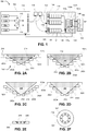
- FIGS. 3A-3D show various configurations of an interfacing device according to one or more embodiments of the disclosed subject matter.
- FIG. 3A shows a top view of the interfacing device.
- FIGS. 3B-3C show a side view and cross-sectional view of the interfacing device in a small breast imaging configuration.
- FIG. 3D shows a side view of the interfacing device in a large breast imaging configuration.
- the interfacing device may include a plurality of annular members 302a-302e, each with an inner surface 310 for contacting a breast 108 during imaging.
- each inner surface 310 includes apertures 308 for directing light to and collecting light from the breast 108.
- Apertures 308 for directing light to the breast 108 i.e., optical input apertures
- the optical input apertures and optical output apertures can be arranged equidistantly about the circumference of the inner surface.
- Optical fibers can be coupled to each aperture 308 by a shaft collar 304 that secures at 306 to the tip of the fiber.
- the angle of the shaft collar 304 (and thus the fiber at the annular member) and/or the inner surface 310 can change based on the size of the annular member 302 so as to keep the input/output substantially normal to the breast tissue surface.
- the shaft collar 304a of the smallest annular member 302a may be disposed at an angle closest to the axial direction of the interfacing device while the shaft collar 304e of the largest annular member 302e may be disposed at angle farther from the axial direction (e.g., almost perpendicular to the axial direction).
- the shaft collars 304 for the other annular members may vary between the extremes of the smallest member 302a and largest member 302e.
- the angle of the shaft collar 304a of the smallest annular member 302a can be 60° with respect to the horizontal plane (i.e., or 30° with respect to the axial direction) and can decrease by approximately 15° for each subsequent annular member 302 in the stack (i.e., 45°, 30°, 15°, 0° with respect to the horizontal plane for shaft collars for members 302b-302e, respectively).
- the inner surface 310 of the smallest annular member 302a can be disposed at angle closest to parallel with the horizontal plane while the inner surface 310 of the largest annular member 302e can be disposed at an angle closest to parallel with the axial direction, with the other annular members 302b-302d having inner surfaces at an angle between the two extremes, as shown in FIG. 3C .
- the interface device can be fabricated, for example, by using 3-D printing of a polymer material. After printing, the parts can be infiltrated with a plastic material to increase the strength and/or rigidity thereof.
- fabrication of the interface device is not limited to the above disclosed techniques. Other fabrication techniques and methodologies are also possible according to one or more contemplated embodiments.
- the interface device may be machined from a block material or molded.
- the translating rings thus provide a way to adjust the fiber positioning to each patient without sacrificing the precise geometric information necessary to create accurate meshes with respect to each source-detector location.
- Each ring's location can be recorded and a new mesh can be created for each patient based on the location of each ring.
- a position detector can be provided for each ring to determine the exact location of each ring and thereby the location of the input/output apertures contained thereon.
- Such position information can be used to reposition the rings and apertures in substantially the same respective positions for subsequent imaging.
- precise positioning may be especially useful for therapy monitoring applications where location of the sources and detectors are carefully maintained across longitudinal imaging time points.
- the system 402 includes the translating ring interface 150 described above.
- the interface 150 is designed for optimal patient comfort, a number of adjustable features can be provided.
- mount 408 can support the imaging interface 150 thereon and can allow for multi-dimension adjustment. For example, the separation between the left and right breast can be changed, as can the height of the breast ring structures.
- the mount 408 can provide multiple degrees of freedom for aligning the interface 150 with the patient's breasts independent of the independent translation of the annular members within the interface 150.
- mount 408 can be similar to a camera mounts with three-dimensional position capability.
- a position detector can be provided so as to record the exact location of the interface. Thus, in longitudinal studies, precise positioning can be maintained across imaging time points.
- the patient can sit in a chair or stool 406 and lean over the interface device 150 to position the breasts within the inner region of the interface device 150.
- Gravity may serve to assist the positioning of the breast within the interface for imaging purposes, for example, by pulling the breast away from the chest of the patient.
- Accommodations may be provided to minimize the stress on the patient during imaging.
- handlebars 404 can be provided for the patient to hold. Handlebars 404 may also serve as a strain release for optical fibers 414, which direct input/output light between the interface 150 and computer 410.
- a head rest (not shown), such as a foam head rest, where the patient can rest her chin and/or forehead can also be provided.
- control unit 410 can interact with control unit 410 to affect imaging of the patient by illuminating with input unit 102 and detecting light from the breasts via detection unit 104.
- Control unit 410 may be configured to process the detected light signals, for example, via detection unit 104 and/or terminal 106 to generate an image of the breast, for example, for viewing on display 412, as described further below.
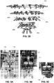
- FIGS. 5A-5C show images of a constructed imaging system.
- the light detection unit 104 allows for the fast collection and processing of large amounts of data.
- An overview of the interactions between the various boards and chips that make up the detection unit 104 is shown in FIG. 6 .
- the detection unit 104 has analog circuitry that amplifies and filters the signal prior to quantization with an analog-to-digital converter 126 (ADC).
- ADC analog-to-digital converter
- the ADC 126 interacts with a complex programmable logic device (CPLD) and digital signal processor (DSP) chip at 128 that work to acquire the signal, demodulate the signal to extract the amplitude, and pass the amplitude onto the host computer 106 via data acquisition cards 140, 142.
- CPLD complex programmable logic device
- DSP digital signal processor
- the DSP and CPLD chips also coordinate the timing of the system and keep the various components synchronized while optimizing the system performance.
- the analog portion of the detection unit 104 involves converting the detected photons into an electronic signal and then conditioning that signal in preparation for digitization.
- a plurality of detector boards 116 n can be provided, corresponding to the number of light outputs desired to be simultaneously detected.
- Each detector board 116 n can include analog electronics with a semiconductor photodetector 118, for example, a silicon photodiode (Si-PD), that converts the incident photons into a current.
- the current can then be amplified and output as a voltage using a trans-impedance amplifier 120 (TIA).
- the TIA 120 can use a bandwidth extension technique to enable high gain and sufficient bandwidth for the 5 kHz and 7 kHz signals to be amplified.
- a passive RC high pass filter can remove the DC component of the signal. From there the signal can pass through a second gain stage referred to as the programmable gain amplifier 124 (PGA) that provides additional amplification, but no additional signal to noise ratio (SNR).
- the PGA is primarily responsible for bringing the signal into a suitable range for detection with the ADC 126. Table 1. Description of the Detection Gain Settings Gain Setting Overall Gain (V/A) TIA Gain (V/A) PGA Gain (V/V) 1 10 k 10 k 1 2 100 k 10 k 10 3 1 M 10 k 100 4 10 M 10 M 1 5 100 M 10 M 10 6 1 G 10 M 100 7 10 G 100 M 100
- three bits can be used to encode a range of gain settings.
- the resistor values for the TIA 120 range from 10 k ⁇ to 100 M ⁇ and the PGA 122 gain ranges from 1 to 100.
- the three gain bits control the resistor value for the TIA 120 and PGA 122 via a multiplexer and reed relays that are used to switch between the values.
- the available gain bits and their TIA and PGA gains are shown in Table 1 above.
- the gain bits can be controlled through the host computer user interface manually or through an automatic detection routine that will test and select the optimal settings.
- the optimal setting is determined as the best signal to noise ratio (SNR) without saturation.
- SNR signal to noise ratio
- the obtained gain signals can be used as feedback to determine if adequate contact has been achieved. If this gain value is higher than anticipated, this may indicate insufficient or improper contact.
- the ring of the interface may be further translated into contact with the breast (e.g., during test illumination and detection) until a gain value closer to an expected value (e.g., indicative of a suitable contact with the tissue surface) is attained.
- the optical feedback signal may be used for feedback control of the actuator of the embodiment of FIG. 14 for example.
- a gain value may be determined based on the quality of a signal from a particular detector or each detector in turn.
- the quality may be determined by comparison to an a priori known reference range or it may be determined by comparing to signals from neighboring detectors.
- Another indicator of whether a particular level of contact has been achieved is for the system to observe the gain or detector signal as the detector is moved toward the target tissue until a signature is indicated, for example, an abrupt change in gain.
- the host computer passes the gain bits to the DSP through a series of shift registers that daisy-chain through the detection boards. Once all of the gain bits have been chained through the boards 116 n , a signal transfers the gain bits into a first-in-first-out (FIFO) buffer for storage on each detection board. During imaging, as the source position is changed, the new gain bit settings are read out locally from the FIFO thereby quickly modifying the resistor values across the TIA 120 and PGA 122.
- FIFO first-in-first-out
- the signal is filtered with an 8th order Butterworth anti-aliasing filter that removes high frequency components and whose primary purpose is to ensure there are no frequencies present above the Nyquist frequency prior to digitization.
- the signal can be sampled at 75 ksamples/s, which means that the Nyquist frequency is 37.5 kHz. As a result, a cutoff frequency of 12.5 kHz can be chosen.
- the Butterworth filter can have a flat passband for the 5 and 7 kHz signals, while also providing strong attenuation of any higher frequency noise at risk of aliasing into the passband.
- an operational amplifier offsets the signal so that it is centered around 2.5 V in order to take advantage of the full 0-5 V input range of the ADC 126.
- the signal is brought into the digital domain using a four channel, 16-bit, successive approximation register (SAR) ADC 126 that samples at a maximum rate of 1 Msamples/s.
- the ADC 126 can sample the data from each detector channel at 75 kHz.
- the ADC timing can be synchronized with the rest of the digital electronics through the master CPLD 126 and DSP 132.
- This DSP-based system utilizes a master-slave architecture for expanding the data acquisition capabilities to multiple DSP chips as opposed to a single DSP chip. Such a design accommodates an increased number of sources, detectors, and wavelengths for breast imaging.
- the master DSP (mDSP) chip 132 is the single DSP that coordinates the behavior of the system, including the other slave DSP (sDSP) chips 130a-130c. It handles all of the handshaking with the host computer and works with the master CPLD (mCPLD) 136 to control the timing of the optical switch, gain bits, and acquisition of the signals from the ADCs 126.
- mCPLD master CPLD
- the mDSP 132 can rely on the mCPLD 136 to control the timing of all of the signals related to shifting and setting the gain bits, controlling the conversion and sampling from the ADCs 126, and sending out the address signals to control the source position of the optical switch.
- the mDSP 132 and mCPLD 136 work closely together to control the timing of the events in the system and to communicate with the other chips.
- the mCPLD 136 is used to communicate the control logic to the detection boards, but the mDSP 132 closely controls the mCPLD 136 and is responsible for timing the 7ms for the optical switch settling.
- Table 2 The intricate way in which the mDSP 132 and mCPLD 136 work together to progress through the various states of setup and acquisition is shown in Table 2.
- the mDSP 132 also relies on a slave CPLD 134 (sCPLD) whose job is to multiplex the incoming data from the detector ADC chips 126 (each responsible for digitizing 4 detector channels) and routing it to the DSP chips for processing. This multiplexing is controlled through a chip select (CS) signal that keeps the CPLDs, ADCs, and DSPs in sync. Each DSP acquires two simultaneous serial streams of data through the A and B serial ports.
- sCPLD slave CPLD 134
- CS chip select
- One DSP is referred to herein as the master DSP 132 (mDSP) because it is in charge of the system, while the other three DSP chips 130a-130c (sDSP1, sDSP2, sDSP3) are referred to as slave chips because they can only respond to one signal (e.g., IMAGING Start) that tells them to either acquire data or sit idly.
- the master-slave configuration helps simplify the control of the system and keeps the data acquisition for all DSP chips in unison. This configuration also allows for easy scaling of the system for a larger number of sources, wavelengths, or detectors which is achieved either by reprogramming the existing DSPs or by adding additional slave DSP chips. Table 2.
- m DSP is idle waiting for a signal from the host computer.
- m CPLD is idle waiting for a signal from the m DSP.
- System Parameters 1. m DSP receives CMD:01 from the host computer telling it to go into the System Parameters state. 2. The host computer sends the number of sources, detectors, and wavelengths to the m DSP. 3. m DSP returns to Standby. * m CPLD remains in Standby. Gain Bit 1. m DSP receives CMD:10 from the host computer telling it to go into the Gain Bit download state. 2. PC sends the gain bits for each source-detector pair. 3.
- m DSP tells the m CPLD to go into Gain Bit state. 4. m DSP sends the m CPLD the # of sources, detectors, wavelengths. 5. m DSP sends the gain bits through the m CPLD to the detection boards while the m CPLD sends out control signals to the Gain Bit Shift Registers and FIFOs. 6. m DSP and m CPLD return to Standby. Imaging 1. m DSP receives CMD:11 from the host computer telling it to acquire one frame. 2. m DSP tells m CPLD to go into Imaging State. 3. m CPLD tells the optical switch to move to the next position. Updates the gain bits by reading from the detection board FIFOs.
- m DSP Waits for the TIMER signal from m DSP. 4. DSP counts to 7ms and then signals TIMER to m CPLD. During that time it also runs the lock-in detection and sends data from previous source back to the PC. 5. m CPLD acquires 150 samples from all detectors. 6. m DSP receives data from the ADC. Returns to step 3 until all sources and wavelength sets are acquired. 7. m DSP and m CPLD return to Standby.
- Each pair of DSP chips can share an 8,192 x 9 dual synchronous FIFO data buffer 138, through which the data is sent back to the host computer 106.
- the DSP chips can write to the FIFO 138, which modifies the 'EMPTY' signal of the FIFO, thereby triggering a request to the host computer 106.
- the host computer 106 then grants the request and triggers a read to the FIFO 138, which sends the data to a user interface 144.
- the FIFO 138 is essentially a data buffer that is responsible for holding the data until the host computer is ready.
- the control signals from the user interface are passed to the detector hardware through a data acquisition card 142, for example, a 24 bit digital I/O interface.
- the data from the DSP chips is acquired by the host computer 106 through a data acquisition card 140, for example, providing 32 digital data lines that are individually configurable as input or output, grouped into four 8-bit ports. Each group of 8-bit ports can be devoted to one DSP in order to handle the data transfer to the host computer.
- Each DSP can be responsible for demodulating the incoming data to extract the amplitude of the signal.
- a digital lock-in detection algorithm can be employed.
- Performing the lock-in detection digitally using a DSP chip as opposed to using traditional analog circuitry not only reduces the amount of hardware required for demodulation, but also provides a more robust solution with better noise performance.
- Simply by reprogramming the DSP chip it is possible to adjust the lock-in frequency, filtering, and the number of detectors.
- DSP-based demodulation is less sensitive to analog component tolerances that can vary with temperature and age as well as between detector channels. To obtain fast imaging speeds, careful coordination between the various components of the system, may be necessary while also accounting for the settling times of the electronics and optical switch. There are many occasions where the system multi-tasks to optimize the imaging speed.
- the system timing is outlined in detail in FIG. 7 .
- the DSPs can acquire 150 samples from each of 128 detectors over a period of 2 ms so that each detector is effectively sampled at 75 ksamples/s.
- the chip select signal (CS) sequentially selects two ADCs per DSP at a time to pass the digitized samples onto that DSP.
- Each 16-bit ADC can digitize two channels at a time and passes them onto the DSP as one 32-bit packet.
- mDSP first receives sample 1 from channels 1&3 of ADCs 1&2, followed by sample 1 from channels 1&3 of ADCs 3&4, followed by sample 1 from channels 1&3 of ADCs 5&6, and finally sample 1 from channels 1&3 of ADCs 7&8.
- sDSP1, sDSP2, and sDSP3 are receiving data from ADCs 9 through 32.
- the sCPLD is responsible for coordinating the routing of the ADC data to the appropriate DSP in each cycle, as coordinated by the chip select (CS) signal.
- the mDSP signals to the mCPLD to change the source position and begins the 7ms pause waiting for the switch to settle.
- the speed of the system is optimized by having the DSPs run the lock-in detection on the samples from the previous source before sending them out to the host computer.
- the gain bits are updated, and the analog electronics have time to settle.
- This system was designed for dynamic breast imaging, making the dynamic range and the speed of acquisition two of the primary criteria.
- the temporal response is limited by the settling time of the optical switch and the number of source positions and wavelengths.
- the switch requires 7 ms to settle after switching positions, followed by 2 ms to acquire the data for all detectors at that source position. This brings the imaging time to 9 ms per source position. Since two wavelength sets are sequentially imaged, the imaging rate also depends on the number of wavelengths. Consequently the fastest the system can image is to collect one frame in 0.009 seconds with one source and 2 wavelengths (e.g., 111 Hz). Or, with 32 sources and 2 wavelengths it can acquire a frame in 0.288 seconds (e.g., 3.5 Hz). Finally, the slowest configuration is to use all 32 sources and 4 wavelengths in which case it takes 0.576 seconds to acquire one frame (e.g., 1.7 Hz).
- Three dimensional reconstructions are performed for the measurement data by using a PDE-constrained multispectral imaging method.
- This method including the diffusion approximation as a light propagation model and the PDE-constrained inverse model of directly recovering chromophore concentrations in tissue, is provide below.
- Q represents a measurement operator that projects the forward solution u( r ) onto the measurable quantity by our digital dynamic imaging system.
- the major chromophores relevant to breast imaging are oxygenated hemoglobin (HbO 2 ), deoxygenated hemoglobin (Hb), water (H 2 O) and lipid, whose molar extinction coefficients are well documented in the literature.
- x is a vector of all unknown chromophores that may include HbO 2 , Hb, H 2 O, or lipid concentrations
- Au b is a system of discretized diffusion equations
- z ⁇ is the measurement at wavelength ⁇
- ⁇ is a regularization parameter that controls a strength of smoothing R .
- a radial basis function (RBF)-type smoothing operator can be used, since it performs better on a grid of unstructured meshes.
- the PDE-constrained multispectral inverse problem can be solved within a framework of the reduced Hessian sequential quadratic programming method (rSQP) that accelerates the reconstruction process.
- C k Au ⁇ ⁇ b p kT .
- the reduced-space formulation is described in detail in " A PDE-constrained SQP algorithm for optical tomography based on the frequency-domain equation of radiative transfer,” published in 2009 in volume 25, number 1 of the journal Inverse Problems .
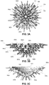
- the method described above can be used to reconstruct chromophores concentrations in breast tissue, as shown, for example in FIG. 8 , which shows static optical images of sagittal slices of a tumor bearing breast over time during a cancer treatment obtained using the disclosed optical imaging system.
- the translating ring interface can include various features designed to provide intimate contact between the input/output apertures of the annular members and the breast surface while avoiding (or at least reducing) uncomfortable compression of the breast tissue.
- radially inner portions having the input/output apertures thereon can be configured to be displaced in a radial direction of the annular members so as to accommodate various breast sizes and shapes.
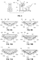
- FIGS. 9A-9B Such an interface is shown in FIGS. 9A-9B .
- the interface includes a plurality of annular members 902a-902e, each with a respective radially inner portion 904 that has an inner surface 906 bounding an inner region of the interface.
- Each annular member 902a-902e includes an actuator 910, for example, a linear actuator, that moves the inner portion 904 in a radial direction so as to contact the inner surface of each annular member 902 with the breast surface 908.
- actuator 910 for example, a linear actuator
- the quality of contact made between the breast and the annular member can be computed based on the amplitude and characteristics of the light detected back from the sensors in the annular member. For example, when no contact is made, an air layer may exist between the light source and the tissue that results in high air-tissue light reflections. These light reflections can cause detected signals from sensors close to the light source that are much larger than expected while detected signals from sensors farther from the light source (e.g., on an opposite side of the breast from the light source aperture) are much lower than expected.
- a closed loop control system can use these detected signals to control the positioning of each annular member for optimal contact.
- the control system can employ pressure sensors , proximity sensors, optical sensors, or acoustic sensors to characterize the contact between the tissue and the annular member in order to optimize the contact.
- radially inner portions can be configured to be displaced by insertion of the breast tissue into the interface, as shown in FIGS. 10A-10B .
- the interface includes a plurality of annular members 1002a-1002e, each with a respective radially inner portion 1004 that has an inner surface 1006 bounding an inner region of the interface.
- the inner portions 1004 can be mounted on flexures 1010, for example, helical springs, that allow motion in the radial direction. At least initially, the inner portions 1004 can define an inner region that is too small to accommodate the size of breast 108, as shown in FIG. 10A .
- flexures 1010 allow motion of the inner portions 1004 in a radially outer direction, thereby keeping the inner surfaces 1006 in intimate contact with the breast surface 1008 with minimal compression of the breast tissue, as shown in FIG. 10B .
- the flexures 1010 may allow rotation of the inner portion 1004 out of the plane of the particular annular member to allow alignment of the inner surface 1006 with the breast surface 1008, thereby further avoiding patient discomfort.
- sensors 1012 can be provided.
- the sensors 1012 can be electromagnetic, optical, or any other sensing capable of providing a measure of displacement of the radially inner portion 1004.
- sensor 1012 can determine the force exerted on flexure 1010, which relates to a displacement of the flexure 1010 and the portion 1004.
- flexure 1010 may include multiple flexures supporting each inner portion 1004. Sensor 1012 for each of the multiple flexures can then be used to determine a radial displacement of the inner portion 1004 as well as an out of plane displacement (e.g., out of plane rotation).
- a difference in forces between the multiple flexures may correspond to an amount of rotation of the inner portion 1004, which can be used to precisely determine a location of the inner portion 1004.
- radially inner portions can be formed of a deformable material so as to conform to breast tissue inserted into the interface, as shown in FIGS. 11A-11B .
- the interface includes a plurality of annular members 1102a-1102e, each with a respective radially inner portion 1104 formed of a deformable material.
- the deformable material may be a flexible polymer, gel-filled bladder, liquid-filled bladder, or air-filled bladder.
- the inner portions 1104 can define an inner region that is too small to accommodate the size of breast 108, as shown in FIG. 11A .
- the interaction between the breast surface 1108 and the inner portion 1104 causes the inner portion 1104 to conform to the breast surface 1108, as shown in FIG. 11B .
- the apertures may be arranged on the inner portion 1104 such that after an expected compression the input/output is substantially perpendicular to the breast surface 1108.
- the ultimate shape of the deformable material 1104 after alteration by the breast insertion can be quantified in order to generate a mesh using optical techniques.
- FIGS. 12A and 12B illustrate an embodiment in which optical elements 1202 and 1204 are indirectly attached to annular elements 1212, 1214, and 1216 by cylinders 1208 that can slide on stems 1210 that rise from and are supported by a base 1220.
- the optical elements 1202 and 1204 (only two are labeled to avoid making the drawing too busy) are adjustable in groups by translating each annular element 1212, 1214, and/or 1216 up or down on the stems 1210.
- each of the optical elements 1202 and 1204 belongs to a ring shaped array of optical elements that can be positioned to define a bounding surface 1224 in the shape of a body part, such as a breast, to be interrogated.
- each stem can be articulated in order to make sufficient angular contact orthogonal to the tissue surface.
- An additional mode of customization of the arrangement of the optical elements may be provided by making expandable or reshapable annular elements as illustrated in Fig. 12B .
- Annular member 1240 may be made such that its overall diameter (and in embodiments, it shape as well) can be increased or reduced, thereby changing the radial separation of the optical elements as well as their axial position.
- the cylinders 1208 are held in openings 1214 in links 1244 connected by hinges 1242 which pivot with sufficient friction to hold an imposed shape and size.
- each interface member can include a multiplicity of sources, for example laser diodes, and a multiplicity of detectors, for example photodiodes, at the location of the apertures.
- Appropriate illumination/detection electronics can be included with each member. Detected data can be conveyed to a central processor, for example, via wireless or wired transfer, for image processing.
- interfaces with ring-shaped and annular configurations have been discussed herein, embodiments of the disclosed subject matter are not limited thereto. Rather, other shapes and configurations allowing for conformal touch contact with the patient body part while providing repeatable, detectable source/detector positions are also contemplated.
- multiple piece-wise continuous members can be used to form each annular section.
- the input/output members of the interface may form a C-shaped, oval, rectangular, or any other shape, so long as the inputs and outputs can be brought into conformal, substantially non-compressive contact with the imaging tissue.
- the input/output members may selectively apply compressive forces to the tissue as part of diagnostic imaging, for example, to determine dynamic vascular response based on the pressure exerted by the input/output members.
- FIG. 13 shows a schematic of a generalized interface for tissue imaging.
- An interface member 1302 can include an optical input and/or output 1304, such as a laser diode and/or photodiode.
- the optical inputs/outputs 1304 can be apertures connected to remote sources and detectors by optical waveguides, as described above.
- each member may have a single optical input and/or a single optical output.
- the system may include a plurality of individual members.
- Each member 1302 can be independently positionable in contact with the tissue surface irrespective of other members 1302 associated with the system.
- a contact determination device 1306 can be provided for detecting when the member 1302 is in contact with the tissue.
- a controller 1312 can use the information provided by the contact determination device 1306 to move the member 1302 into contact with the tissue using actuator 1308.
- the actuator 1308 may be capable of moving the member 1302 in multiple directions, for example, in at least two dimensions, as well as rotationally so as to position an interrogation/detection surface of the member 1302 into conformal contact with the tissue surface.
- Processor 1310 can use position information of the member 1302 provided by controller 1312 based on the actuation in constructing the imaging mesh.
- Each member 1302 can represent a particular point of the imaging mesh, with each member 1302 being positioned at a desired mesh position (e.g., with respect to prior imaging sessions).
- the imaging interface with a plurality of interface members 1302 can thus conform to a variety of tissue geometries and shapes without necessarily being constrained to a ring or annular geometry.
- FIG. 14 shows an actuator 1262 configured to move a probe head 1264 such that it makes suitable contact with a body part surface 1266 or such that the probe head 1264 applies pressure to and removes pressure from the body part in order to induce a change in the tissue that is contemporaneously interrogated.
- the force of the actuator may be used to push blood away from the site and then the release or reduction of that force may allow blood to flow back.
- successive image frames or other data may be captured to allow instantaneous or time-averaged indications of the concentration and location of chromophores.
- the imaging system connected to the probe can also be used for determining whether contact is made or not.
- Various control goals may be used for governing the actuation of the probe head.
- the mesh for imaging can be generated based on encoder values for each of the source/detector positions, e.g., based on the positions of the annular member.
- the optimal position of each annular member and/or the source/detector positions therein can be estimated or predicted based on previously obtained information regarding the tissue or the patient. For example, information regarding patient weight, height, age, body-mass index, bra size, and/or images of the patient (e.g., MRI, CT, PET, or optical images) can be used to determine an optimal initial configuration of the imaging setup, including, but not limited to, patient chair height, interface height and tilt, initial interface member arrangement, number of interface members, etc. Fine tuning to provide contact of the imaging interface with the patient tissue can be accomplished via feedback controlled actuation.
- Embodiments of the disclosed subject matter thus avoid issues associated with other breast imaging interfaces, namely, incomplete breast coverage, the inability to image a range of breast sizes (A to DDD), the use of matching fluid, the use of compression, the inability to extract the precise optical input/output positioning.
Landscapes
- Health & Medical Sciences (AREA)
- Life Sciences & Earth Sciences (AREA)
- Biomedical Technology (AREA)
- Molecular Biology (AREA)
- Veterinary Medicine (AREA)
- Biophysics (AREA)
- Pathology (AREA)
- Engineering & Computer Science (AREA)
- Public Health (AREA)
- Heart & Thoracic Surgery (AREA)
- Medical Informatics (AREA)
- Physics & Mathematics (AREA)
- Surgery (AREA)
- Animal Behavior & Ethology (AREA)
- General Health & Medical Sciences (AREA)
- Nuclear Medicine, Radiotherapy & Molecular Imaging (AREA)
- Radiology & Medical Imaging (AREA)
- Investigating Or Analysing Materials By Optical Means (AREA)
- Apparatus For Radiation Diagnosis (AREA)
Claims (13)
- Structure (150) pour interfaçage d'une partie corporelle (108) d'un patient avec une pluralité de sources destinées à délivrer de la lumière d'illumination à la partie corporelle et une pluralité de détecteurs destinés à collecter la lumière issue de la partie corporelle, respectivement, en vue d'effectuer une tomographie optique diffuse, la structure comprenant :un premier jeu d'au moins 3 organes de support annulaires attachés mutuellement (202a à 202e) de diamètres croissants pour les sources et les détecteurs, lesdits organes de support annulaires étant positionnés au sommet les uns des autres avec l'organe de support annulaire (202a) ayant le plus petit diamètre au fond,dans laquelle les organes de support annulaires forment ensemble une structure en forme de coupe configurée pour y tenir la partie corporelle,chacun des organes de support annulaires est attaché de façon détachable à un organe de support annulaire adjacent et la structure est adaptée pour assurer un déplacement réglable dans une direction axiale,le nombre d'organes de support annulaires est réglable en enlevant certains des organes de support annulaires pour accueillir diverses tailles de partie corporelle,les déplacements dans la direction axiale des organes de support annulaires sont réglables à partir de la taille et de la forme de la partie corporelle, etchaque organe de support annulaire comporte une pluralité de sources et de détecteurs, des ouvertures optiques (308),la structure est adaptée pour que chaque organe de support annulaire puisse être indépendamment déplacé dans la direction axiale des organes de support annulaires et puisse être facultativement tourné hors de plan pour en amener une surface en contact de toucher avec la partie corporelle.
- Structure selon la revendication 1, comprenant en outre un second jeu d'une pluralité d'organes de support annulaires positionnés adjacents au premier jeu d'organes de support annulaires (202a à 202e) de telle sorte que lorsque la partie corporelle (108) est des seins, chaque jeu est adapté pour tenir un sein correspondant.
- Structure selon la revendication 1, dans laquelle les organes de support annulaires (202a à 202e) sont constitués d'un matériau flexible.
- Structure selon la revendication 1, dans laquelle le diamètre de chaque organe de support annulaire (202a à 202e) est réglable.
- Structure selon la revendication 1, comprenant en outre un dispositif de translation (1308) relié à chaque organe de support annulaire pour déplacer indépendamment chaque organe de support annulaire le long d'une direction axiale.
- Structure selon la revendication 5, comprenant en outre un organe de commande (1312) destiné à commander les dispositifs de translation (1308) et au moins un capteur de contact (1306),
dans laquelle le dispositif de translation (1308) inclut un actionneur,
l'au moins un capteur de contact (1306) est configuré pour fournir une indication de contact d'une surface de l'un des organes de support annulaires avec la partie corporelle (108), et
l'organe de commande (1312) est configuré pour réguler le déplacement de chaque organe de support annulaire en réaction à un signal issu de l'au moins un capteur de contact (1306). - Structure d'interface (150) selon l'une quelconque des revendications 1 à 3, utilisée dans un système d'imagerie numérique destiné à collecter des données de tomographie optique diffuse en vue de reconstruire une image de la partie corporelle (108).
- Procédé de fabrication d'une structure d'interfaçage (150) telle que revendiquée dans la revendication 1, comprenant :- la production des organes de support annulaires (202a à 202e) de la structure d'interfaçage (150) par impression en 3D d'un matériau polymère ; et- l'infiltration des organes de support annulaires (202a à 202e) avec un matériau plastique.
- Système d'interfaçage d'une partie corporelle (108) d'un patient avec une pluralité de sources délivrant de la lumière d'illumination à la partie corporelle (108) et avec une pluralité de détecteurs collectant la lumière issue de la partie corporelle (108) de façon à effectuer une tomographie optique diffuse, le système comprenant :une structure d'interface (150) telle que revendiquée dans la revendication 2 ; etun dispositif de tenue (408) destiné à tenir les premier et second jeux d'organes de support annulaires adjacents l'un à l'autre de telle sorte que chaque jeu tienne un sein correspondant (108),la distance entre les premier et second jeux étant réglable pour correspondre à la distance entre les seins.
- Système selon la revendication 9, comprenant une pluralité de diodes laser en tant que sources d'illumination.
- Système selon la revendication 9, comprenant une pluralité de photodiodes en silicium en tant que détecteurs.
- Système selon la revendication 9, incluant en outre un processeur (410), dans lequel le processeur (410) est configuré pour reconstruire une image de tissu du sein à partir des signaux de lumière détectés.
- Système selon la revendication 12, dans lequel le processeur (410) est configuré pour utiliser la position de chaque organe de support annulaire dans la reconstruction de l'image du tissu du sein.
Applications Claiming Priority (2)
| Application Number | Priority Date | Filing Date | Title |
|---|---|---|---|
| US201161541503P | 2011-09-30 | 2011-09-30 | |
| PCT/US2012/058004 WO2013049629A1 (fr) | 2011-09-30 | 2012-09-28 | Systèmes, dispositifs et procédés d'interfaçage pour imagerie optique |
Publications (3)
| Publication Number | Publication Date |
|---|---|
| EP2761327A1 EP2761327A1 (fr) | 2014-08-06 |
| EP2761327A4 EP2761327A4 (fr) | 2015-04-08 |
| EP2761327B1 true EP2761327B1 (fr) | 2019-09-18 |
Family
ID=47996451
Family Applications (1)
| Application Number | Title | Priority Date | Filing Date |
|---|---|---|---|
| EP12837252.1A Active EP2761327B1 (fr) | 2011-09-30 | 2012-09-28 | Systèmes et dispositifs d'interfaçage pour imagerie optique |
Country Status (5)
| Country | Link |
|---|---|
| US (1) | US10376150B2 (fr) |
| EP (1) | EP2761327B1 (fr) |
| JP (1) | JP2014533126A (fr) |
| KR (1) | KR20140096043A (fr) |
| WO (1) | WO2013049629A1 (fr) |
Families Citing this family (12)
| Publication number | Priority date | Publication date | Assignee | Title |
|---|---|---|---|---|
| JP5848590B2 (ja) * | 2011-12-02 | 2016-01-27 | 浜松ホトニクス株式会社 | 乳房撮像装置 |
| JP6120647B2 (ja) * | 2013-04-04 | 2017-04-26 | キヤノン株式会社 | 被検体情報取得装置およびその制御方法 |
| US9216004B2 (en) * | 2013-09-12 | 2015-12-22 | Jesse Talant | Adam and ease mammography device |
| JP2015109948A (ja) * | 2013-10-31 | 2015-06-18 | キヤノン株式会社 | 被検体情報取得装置 |
| TWI577345B (zh) * | 2015-02-09 | 2017-04-11 | 國立中央大學 | A circular scanning device for optical tomography systems |
| US9861319B2 (en) | 2015-03-23 | 2018-01-09 | University Of Kentucky Research Foundation | Noncontact three-dimensional diffuse optical imaging of deep tissue blood flow distribution |
| JP6794438B2 (ja) * | 2015-06-03 | 2020-12-02 | ノヴァウラ ソチエタ レスポンサビリタ リミタータNovaura S.R.L. | 乳房検診を容易にする装置を備える画像診断システム |
| JP6570497B2 (ja) * | 2016-09-21 | 2019-09-04 | 富士フイルム株式会社 | 計測装置 |
| US11291371B2 (en) * | 2019-07-16 | 2022-04-05 | Sergio Lara Pereira Monteiro | Method and means to make infrared image of the female breast, other human organs and other objects |
| US11304456B2 (en) | 2019-07-28 | 2022-04-19 | Holovisions LLC | Smart bra with optical sensors to detect abnormal breast tissue |
| US11950881B2 (en) | 2019-07-28 | 2024-04-09 | Holovsions LLC | Smart bra for optical scanning of breast tissue to detect abnormal tissue with selectively-expandable components to reduce air gaps |
| CN111466875B (zh) * | 2020-03-12 | 2021-08-24 | 西安电子科技大学 | 一种旋转式扩散光学成像系统 |
Family Cites Families (23)
| Publication number | Priority date | Publication date | Assignee | Title |
|---|---|---|---|---|
| JPH0644510U (ja) * | 1992-09-30 | 1994-06-14 | 株式会社島津製作所 | 光走査装置 |
| US5860934A (en) | 1992-12-21 | 1999-01-19 | Artann Corporation | Method and device for mechanical imaging of breast |
| JP3000858U (ja) * | 1994-02-08 | 1994-08-16 | パワーアップジャパン株式会社 | スポイト |
| JP3351151B2 (ja) * | 1994-12-29 | 2002-11-25 | 株式会社島津製作所 | 生体計測用光プローブ装置 |
| US6236050B1 (en) * | 1996-02-02 | 2001-05-22 | TüMER TüMAY O. | Method and apparatus for radiation detection |
| EP1006866A1 (fr) | 1996-11-29 | 2000-06-14 | Imaging Diagnostic Systems, Inc. | Reseau de detection utilise dans un appareil d'imagerie laser |
| US6081322A (en) * | 1997-10-16 | 2000-06-27 | Research Foundation Of State Of New York | NIR clinical opti-scan system |
| CA2309214C (fr) | 1997-11-26 | 2004-07-20 | Imaging Diagnostic Systems, Inc. | Appareil pour imagerie mammaire a resolution temporelle |
| WO1999040840A1 (fr) * | 1998-02-11 | 1999-08-19 | Non-Invasive Technology, Inc. | Detection, visualisation et caracterisation de carcinomes mammaires |
| JPH11230090A (ja) * | 1998-02-12 | 1999-08-24 | Nec Eng Ltd | ファンガード |
| WO2000006016A1 (fr) | 1998-07-30 | 2000-02-10 | Yissum Research Development Company Of The Hebrew University Of Jerusalem | Mammographie optique |
| CA2366536A1 (fr) * | 1999-04-14 | 2000-10-19 | Jack Edward Juni | Systeme de tomographie d'emission monophotonique |
| US7349731B2 (en) * | 2002-06-07 | 2008-03-25 | Clemson University Research Foundation | Reconstructed refractive index spatial maps and method with algorithm |
| US8095204B2 (en) | 2002-08-09 | 2012-01-10 | Interstitial, Llc | Apparatus and method for diagnosing breast cancer including examination table |
| US6749570B2 (en) * | 2002-08-23 | 2004-06-15 | Acuson Corporation | Ultrasound method and apparatus for imaging breast |
| EP1807000A1 (fr) * | 2004-09-24 | 2007-07-18 | Art Advanced Research Technologies Inc. | Procede d'imagerie optique pour caracteriser des tissus |
| US7332722B1 (en) * | 2006-02-21 | 2008-02-19 | Jefferson Science Associates, Llc | Simultaneous multi-headed imager geometry calibration method |
| US7683332B2 (en) | 2006-12-08 | 2010-03-23 | Rush University Medical Center | Integrated single photon emission computed tomography (SPECT)/transmission computed tomography (TCT) system for cardiac imaging |
| WO2009033035A1 (fr) | 2007-09-06 | 2009-03-12 | Orbital Therapy Llc | Système de support de patiente pour un accès total pendant une radiothérapie du sein en décubitus ventral |
| US20100274161A1 (en) * | 2007-10-15 | 2010-10-28 | Slender Medical, Ltd. | Implosion techniques for ultrasound |
| EP2222221A1 (fr) | 2007-12-17 | 2010-09-01 | Koninklijke Philips Electronics N.V. | Procédé d'évaluation de la qualité d'une mesure et dispositif d'imagerie de l'intérieur d'un milieu |
| WO2009114852A2 (fr) * | 2008-03-14 | 2009-09-17 | The Trustees Of Columbia University In The City Of New York | Procédés et systèmes pour former des images dynamiques de tissus en par tomographie optique numérique |
| CN103347439B (zh) | 2010-11-11 | 2016-02-17 | 纽约市哥伦比亚大学托管会 | 动态光学层析成像系统 |
-
2012
- 2012-09-28 KR KR1020147011239A patent/KR20140096043A/ko not_active Application Discontinuation
- 2012-09-28 EP EP12837252.1A patent/EP2761327B1/fr active Active
- 2012-09-28 WO PCT/US2012/058004 patent/WO2013049629A1/fr active Application Filing
- 2012-09-28 JP JP2014533418A patent/JP2014533126A/ja active Pending
- 2012-09-28 US US14/348,072 patent/US10376150B2/en active Active
Non-Patent Citations (1)
| Title |
|---|
| None * |
Also Published As
| Publication number | Publication date |
|---|---|
| EP2761327A1 (fr) | 2014-08-06 |
| WO2013049629A1 (fr) | 2013-04-04 |
| KR20140096043A (ko) | 2014-08-04 |
| JP2014533126A (ja) | 2014-12-11 |
| EP2761327A4 (fr) | 2015-04-08 |
| US20140236003A1 (en) | 2014-08-21 |
| US10376150B2 (en) | 2019-08-13 |
Similar Documents
| Publication | Publication Date | Title |
|---|---|---|
| EP2761327B1 (fr) | Systèmes et dispositifs d'interfaçage pour imagerie optique | |
| Flexman et al. | Digital optical tomography system for dynamic breast imaging | |
| US8788003B2 (en) | Monitoring blood constituent levels in biological tissue | |
| EP1219241B1 (fr) | Stethoscope | |
| Kacprzak et al. | Time-resolved optical imager for assessment of cerebral oxygenation | |
| JP2013545543A (ja) | 動的光トモグラフィーイメージング装置、方法、およびシステム | |
| CN108542358B (zh) | 基于光声成像的脉象七维信息自动获取的设备和方法 | |
| WO2013049677A1 (fr) | Procédés, et systèmes et dispositifs optiques compacts d'imagerie | |
| JP2012053053A (ja) | 散乱媒体の動的性質のトモグラフィ画像化システム及び方法 | |
| Yaqub et al. | Compact, portable, high-density functional near-infrared spectroscopy system for brain imaging | |
| Hou et al. | Portable near-infrared technologies and devices for noninvasive assessment of tissue hemodynamics | |
| JP4652643B2 (ja) | 高解像度ダイナミックデジタル赤外線イメージングのための方法および装置 | |
| EP1556672A2 (fr) | Procede et appareil de mesure de mouvements d'oscillation | |
| WO2020043115A1 (fr) | Dispositif de détection et procédé de détection pour combiner détection tactile et imagerie par tomographie optique | |
| Flexman | Dynamic digital optical tomography for cancer imaging and therapy monitoring | |
| CN109044282B (zh) | 融合触觉传感和光断层扫描成像的检测装置与检测方法 | |
| Al Abdi et al. | A dual-mode simultaneous bilateral optical imaging system for breast cancer detection | |
| Al Abdi et al. | A Robotic, Dual-Sensing, Functional Optical Imaging System for Breast Cancer Detection | |
| Cheng et al. | A novel optical scanning system for breast cancer imaging | |
| Prompalit et al. | Development of non-contact device based on optical fibre technology for detecting respiration of small animal in imaging instruments | |
| Yu et al. | Sono-contrast spectroscopy for breast cancer detection | |
| Lasker et al. | Dynamic optical tomographic imager with optimized digital lock-in filtering | |
| Barbour et al. | Functional imaging of the vascular bed by dynamic optical tomography | |
| Schmitz et al. | A Dual-mode simultaneous bilateral optical imaging system for breast cancer detection | |
| Lasker et al. | Three-dimensional optical-tomographic dynamic imaging of small tissue volumes |
Legal Events
| Date | Code | Title | Description |
|---|---|---|---|
| PUAI | Public reference made under article 153(3) epc to a published international application that has entered the european phase |
Free format text: ORIGINAL CODE: 0009012 |
|
| 17P | Request for examination filed |
Effective date: 20140430 |
|
| AK | Designated contracting states |
Kind code of ref document: A1 Designated state(s): AL AT BE BG CH CY CZ DE DK EE ES FI FR GB GR HR HU IE IS IT LI LT LU LV MC MK MT NL NO PL PT RO RS SE SI SK SM TR |
|
| DAX | Request for extension of the european patent (deleted) | ||
| RA4 | Supplementary search report drawn up and despatched (corrected) |
Effective date: 20150305 |
|
| RIC1 | Information provided on ipc code assigned before grant |
Ipc: G01T 1/166 20060101AFI20150227BHEP Ipc: A61B 5/00 20060101ALN20150227BHEP |
|
| STAA | Information on the status of an ep patent application or granted ep patent |
Free format text: STATUS: EXAMINATION IS IN PROGRESS |
|
| 17Q | First examination report despatched |
Effective date: 20171207 |
|
| RIC1 | Information provided on ipc code assigned before grant |
Ipc: G01T 1/166 20060101AFI20190307BHEP Ipc: A61B 5/00 20060101ALN20190307BHEP |
|
| GRAP | Despatch of communication of intention to grant a patent |
Free format text: ORIGINAL CODE: EPIDOSNIGR1 |
|
| STAA | Information on the status of an ep patent application or granted ep patent |
Free format text: STATUS: GRANT OF PATENT IS INTENDED |
|
| INTG | Intention to grant announced |
Effective date: 20190424 |
|
| GRAS | Grant fee paid |
Free format text: ORIGINAL CODE: EPIDOSNIGR3 |
|
| GRAA | (expected) grant |
Free format text: ORIGINAL CODE: 0009210 |
|
| STAA | Information on the status of an ep patent application or granted ep patent |
Free format text: STATUS: THE PATENT HAS BEEN GRANTED |
|
| AK | Designated contracting states |
Kind code of ref document: B1 Designated state(s): AL AT BE BG CH CY CZ DE DK EE ES FI FR GB GR HR HU IE IS IT LI LT LU LV MC MK MT NL NO PL PT RO RS SE SI SK SM TR |
|
| REG | Reference to a national code |
Ref country code: GB Ref legal event code: FG4D |
|
| REG | Reference to a national code |
Ref country code: CH Ref legal event code: EP |
|
| REG | Reference to a national code |
Ref country code: DE Ref legal event code: R096 Ref document number: 602012064182 Country of ref document: DE |
|
| REG | Reference to a national code |
Ref country code: AT Ref legal event code: REF Ref document number: 1181991 Country of ref document: AT Kind code of ref document: T Effective date: 20191015 |
|
| REG | Reference to a national code |
Ref country code: IE Ref legal event code: FG4D |
|
| REG | Reference to a national code |
Ref country code: NL Ref legal event code: MP Effective date: 20190918 |
|
| PG25 | Lapsed in a contracting state [announced via postgrant information from national office to epo] |
Ref country code: HR Free format text: LAPSE BECAUSE OF FAILURE TO SUBMIT A TRANSLATION OF THE DESCRIPTION OR TO PAY THE FEE WITHIN THE PRESCRIBED TIME-LIMIT Effective date: 20190918 Ref country code: LT Free format text: LAPSE BECAUSE OF FAILURE TO SUBMIT A TRANSLATION OF THE DESCRIPTION OR TO PAY THE FEE WITHIN THE PRESCRIBED TIME-LIMIT Effective date: 20190918 Ref country code: NO Free format text: LAPSE BECAUSE OF FAILURE TO SUBMIT A TRANSLATION OF THE DESCRIPTION OR TO PAY THE FEE WITHIN THE PRESCRIBED TIME-LIMIT Effective date: 20191218 Ref country code: BG Free format text: LAPSE BECAUSE OF FAILURE TO SUBMIT A TRANSLATION OF THE DESCRIPTION OR TO PAY THE FEE WITHIN THE PRESCRIBED TIME-LIMIT Effective date: 20191218 Ref country code: FI Free format text: LAPSE BECAUSE OF FAILURE TO SUBMIT A TRANSLATION OF THE DESCRIPTION OR TO PAY THE FEE WITHIN THE PRESCRIBED TIME-LIMIT Effective date: 20190918 Ref country code: SE Free format text: LAPSE BECAUSE OF FAILURE TO SUBMIT A TRANSLATION OF THE DESCRIPTION OR TO PAY THE FEE WITHIN THE PRESCRIBED TIME-LIMIT Effective date: 20190918 |
|
| REG | Reference to a national code |
Ref country code: LT Ref legal event code: MG4D |
|
| PG25 | Lapsed in a contracting state [announced via postgrant information from national office to epo] |
Ref country code: RS Free format text: LAPSE BECAUSE OF FAILURE TO SUBMIT A TRANSLATION OF THE DESCRIPTION OR TO PAY THE FEE WITHIN THE PRESCRIBED TIME-LIMIT Effective date: 20190918 Ref country code: GR Free format text: LAPSE BECAUSE OF FAILURE TO SUBMIT A TRANSLATION OF THE DESCRIPTION OR TO PAY THE FEE WITHIN THE PRESCRIBED TIME-LIMIT Effective date: 20191219 Ref country code: AL Free format text: LAPSE BECAUSE OF FAILURE TO SUBMIT A TRANSLATION OF THE DESCRIPTION OR TO PAY THE FEE WITHIN THE PRESCRIBED TIME-LIMIT Effective date: 20190918 Ref country code: LV Free format text: LAPSE BECAUSE OF FAILURE TO SUBMIT A TRANSLATION OF THE DESCRIPTION OR TO PAY THE FEE WITHIN THE PRESCRIBED TIME-LIMIT Effective date: 20190918 |
|
| REG | Reference to a national code |
Ref country code: AT Ref legal event code: MK05 Ref document number: 1181991 Country of ref document: AT Kind code of ref document: T Effective date: 20190918 |
|
| PG25 | Lapsed in a contracting state [announced via postgrant information from national office to epo] |
Ref country code: NL Free format text: LAPSE BECAUSE OF FAILURE TO SUBMIT A TRANSLATION OF THE DESCRIPTION OR TO PAY THE FEE WITHIN THE PRESCRIBED TIME-LIMIT Effective date: 20190918 Ref country code: AT Free format text: LAPSE BECAUSE OF FAILURE TO SUBMIT A TRANSLATION OF THE DESCRIPTION OR TO PAY THE FEE WITHIN THE PRESCRIBED TIME-LIMIT Effective date: 20190918 Ref country code: EE Free format text: LAPSE BECAUSE OF FAILURE TO SUBMIT A TRANSLATION OF THE DESCRIPTION OR TO PAY THE FEE WITHIN THE PRESCRIBED TIME-LIMIT Effective date: 20190918 Ref country code: PT Free format text: LAPSE BECAUSE OF FAILURE TO SUBMIT A TRANSLATION OF THE DESCRIPTION OR TO PAY THE FEE WITHIN THE PRESCRIBED TIME-LIMIT Effective date: 20200120 Ref country code: IT Free format text: LAPSE BECAUSE OF FAILURE TO SUBMIT A TRANSLATION OF THE DESCRIPTION OR TO PAY THE FEE WITHIN THE PRESCRIBED TIME-LIMIT Effective date: 20190918 Ref country code: RO Free format text: LAPSE BECAUSE OF FAILURE TO SUBMIT A TRANSLATION OF THE DESCRIPTION OR TO PAY THE FEE WITHIN THE PRESCRIBED TIME-LIMIT Effective date: 20190918 Ref country code: PL Free format text: LAPSE BECAUSE OF FAILURE TO SUBMIT A TRANSLATION OF THE DESCRIPTION OR TO PAY THE FEE WITHIN THE PRESCRIBED TIME-LIMIT Effective date: 20190918 Ref country code: ES Free format text: LAPSE BECAUSE OF FAILURE TO SUBMIT A TRANSLATION OF THE DESCRIPTION OR TO PAY THE FEE WITHIN THE PRESCRIBED TIME-LIMIT Effective date: 20190918 |
|
| PG25 | Lapsed in a contracting state [announced via postgrant information from national office to epo] |
Ref country code: SK Free format text: LAPSE BECAUSE OF FAILURE TO SUBMIT A TRANSLATION OF THE DESCRIPTION OR TO PAY THE FEE WITHIN THE PRESCRIBED TIME-LIMIT Effective date: 20190918 Ref country code: CZ Free format text: LAPSE BECAUSE OF FAILURE TO SUBMIT A TRANSLATION OF THE DESCRIPTION OR TO PAY THE FEE WITHIN THE PRESCRIBED TIME-LIMIT Effective date: 20190918 Ref country code: IS Free format text: LAPSE BECAUSE OF FAILURE TO SUBMIT A TRANSLATION OF THE DESCRIPTION OR TO PAY THE FEE WITHIN THE PRESCRIBED TIME-LIMIT Effective date: 20200224 Ref country code: SM Free format text: LAPSE BECAUSE OF FAILURE TO SUBMIT A TRANSLATION OF THE DESCRIPTION OR TO PAY THE FEE WITHIN THE PRESCRIBED TIME-LIMIT Effective date: 20190918 |
|
| REG | Reference to a national code |
Ref country code: CH Ref legal event code: PL |
|
| REG | Reference to a national code |
Ref country code: DE Ref legal event code: R097 Ref document number: 602012064182 Country of ref document: DE |
|
| PLBE | No opposition filed within time limit |
Free format text: ORIGINAL CODE: 0009261 |
|
| STAA | Information on the status of an ep patent application or granted ep patent |
Free format text: STATUS: NO OPPOSITION FILED WITHIN TIME LIMIT |
|
| PG2D | Information on lapse in contracting state deleted |
Ref country code: IS |
|
| PG25 | Lapsed in a contracting state [announced via postgrant information from national office to epo] |
Ref country code: IE Free format text: LAPSE BECAUSE OF NON-PAYMENT OF DUE FEES Effective date: 20190928 Ref country code: CH Free format text: LAPSE BECAUSE OF NON-PAYMENT OF DUE FEES Effective date: 20190930 Ref country code: DK Free format text: LAPSE BECAUSE OF FAILURE TO SUBMIT A TRANSLATION OF THE DESCRIPTION OR TO PAY THE FEE WITHIN THE PRESCRIBED TIME-LIMIT Effective date: 20190918 Ref country code: LU Free format text: LAPSE BECAUSE OF NON-PAYMENT OF DUE FEES Effective date: 20190928 Ref country code: LI Free format text: LAPSE BECAUSE OF NON-PAYMENT OF DUE FEES Effective date: 20190930 Ref country code: IS Free format text: LAPSE BECAUSE OF FAILURE TO SUBMIT A TRANSLATION OF THE DESCRIPTION OR TO PAY THE FEE WITHIN THE PRESCRIBED TIME-LIMIT Effective date: 20200119 |
|
| REG | Reference to a national code |
Ref country code: BE Ref legal event code: MM Effective date: 20190930 |
|
| 26N | No opposition filed |
Effective date: 20200619 |
|
| PG25 | Lapsed in a contracting state [announced via postgrant information from national office to epo] |
Ref country code: SI Free format text: LAPSE BECAUSE OF FAILURE TO SUBMIT A TRANSLATION OF THE DESCRIPTION OR TO PAY THE FEE WITHIN THE PRESCRIBED TIME-LIMIT Effective date: 20190918 Ref country code: MC Free format text: LAPSE BECAUSE OF FAILURE TO SUBMIT A TRANSLATION OF THE DESCRIPTION OR TO PAY THE FEE WITHIN THE PRESCRIBED TIME-LIMIT Effective date: 20190918 Ref country code: BE Free format text: LAPSE BECAUSE OF NON-PAYMENT OF DUE FEES Effective date: 20190930 |
|
| PG25 | Lapsed in a contracting state [announced via postgrant information from national office to epo] |
Ref country code: CY Free format text: LAPSE BECAUSE OF FAILURE TO SUBMIT A TRANSLATION OF THE DESCRIPTION OR TO PAY THE FEE WITHIN THE PRESCRIBED TIME-LIMIT Effective date: 20190918 |
|
| PG25 | Lapsed in a contracting state [announced via postgrant information from national office to epo] |
Ref country code: MT Free format text: LAPSE BECAUSE OF FAILURE TO SUBMIT A TRANSLATION OF THE DESCRIPTION OR TO PAY THE FEE WITHIN THE PRESCRIBED TIME-LIMIT Effective date: 20190918 Ref country code: HU Free format text: LAPSE BECAUSE OF FAILURE TO SUBMIT A TRANSLATION OF THE DESCRIPTION OR TO PAY THE FEE WITHIN THE PRESCRIBED TIME-LIMIT; INVALID AB INITIO Effective date: 20120928 |
|
| PG25 | Lapsed in a contracting state [announced via postgrant information from national office to epo] |
Ref country code: TR Free format text: LAPSE BECAUSE OF FAILURE TO SUBMIT A TRANSLATION OF THE DESCRIPTION OR TO PAY THE FEE WITHIN THE PRESCRIBED TIME-LIMIT Effective date: 20190918 |
|
| PG25 | Lapsed in a contracting state [announced via postgrant information from national office to epo] |
Ref country code: MK Free format text: LAPSE BECAUSE OF FAILURE TO SUBMIT A TRANSLATION OF THE DESCRIPTION OR TO PAY THE FEE WITHIN THE PRESCRIBED TIME-LIMIT Effective date: 20190918 |
|
| P01 | Opt-out of the competence of the unified patent court (upc) registered |
Effective date: 20230314 |
|
| PGFP | Annual fee paid to national office [announced via postgrant information from national office to epo] |
Ref country code: GB Payment date: 20230927 Year of fee payment: 12 |
|
| PGFP | Annual fee paid to national office [announced via postgrant information from national office to epo] |
Ref country code: FR Payment date: 20230925 Year of fee payment: 12 Ref country code: DE Payment date: 20230927 Year of fee payment: 12 |