EP2761075B1 - Anordnung mit einem laugenbehälter einer waschmaschine und einem antriebsmotor sowie waschmaschine - Google Patents
Anordnung mit einem laugenbehälter einer waschmaschine und einem antriebsmotor sowie waschmaschine Download PDFInfo
- Publication number
- EP2761075B1 EP2761075B1 EP12759436.4A EP12759436A EP2761075B1 EP 2761075 B1 EP2761075 B1 EP 2761075B1 EP 12759436 A EP12759436 A EP 12759436A EP 2761075 B1 EP2761075 B1 EP 2761075B1
- Authority
- EP
- European Patent Office
- Prior art keywords
- drive motor
- tub
- arrangement
- washing machine
- motor
- Prior art date
- Legal status (The legal status is an assumption and is not a legal conclusion. Google has not performed a legal analysis and makes no representation as to the accuracy of the status listed.)
- Active
Links
Images
Classifications
-
- D—TEXTILES; PAPER
- D06—TREATMENT OF TEXTILES OR THE LIKE; LAUNDERING; FLEXIBLE MATERIALS NOT OTHERWISE PROVIDED FOR
- D06F—LAUNDERING, DRYING, IRONING, PRESSING OR FOLDING TEXTILE ARTICLES
- D06F37/00—Details specific to washing machines covered by groups D06F21/00 - D06F25/00
- D06F37/20—Mountings, e.g. resilient mountings, for the rotary receptacle, motor, tub or casing; Preventing or damping vibrations
- D06F37/206—Mounting of motor
-
- D—TEXTILES; PAPER
- D06—TREATMENT OF TEXTILES OR THE LIKE; LAUNDERING; FLEXIBLE MATERIALS NOT OTHERWISE PROVIDED FOR
- D06F—LAUNDERING, DRYING, IRONING, PRESSING OR FOLDING TEXTILE ARTICLES
- D06F37/00—Details specific to washing machines covered by groups D06F21/00 - D06F25/00
- D06F37/20—Mountings, e.g. resilient mountings, for the rotary receptacle, motor, tub or casing; Preventing or damping vibrations
-
- H—ELECTRICITY
- H02—GENERATION; CONVERSION OR DISTRIBUTION OF ELECTRIC POWER
- H02K—DYNAMO-ELECTRIC MACHINES
- H02K5/00—Casings; Enclosures; Supports
- H02K5/04—Casings or enclosures characterised by the shape, form or construction thereof
-
- H—ELECTRICITY
- H02—GENERATION; CONVERSION OR DISTRIBUTION OF ELECTRIC POWER
- H02K—DYNAMO-ELECTRIC MACHINES
- H02K5/00—Casings; Enclosures; Supports
- H02K5/26—Means for adjusting casings relative to their supports
Definitions
- the invention relates to an arrangement with a tub of a washing machine and a drive motor, which is connectable with a suspension device with the tub, wherein the suspension device is designed as a 2-point connection. Furthermore, the invention also relates to a washing machine with such an arrangement.
- arms are formed on a tub, which are provided for receiving a shaft of a motor.
- the shaft is thereby fastened with a first end to the first arm, wherein the opposite end of the shaft is fastened to the second arm.
- the axis of the shaft is therefore always oriented parallel or coaxial with a connecting line between the two arms.
- the attachment of the motor is in this respect inadequate in terms of accessibility and installation.
- Such a 2-point connection is therefore disadvantageous for the low wear of the engine, in particular the shaft.
- this has a tub of a washing machine and a drive motor.
- the drive motor can be connected to the tub by means of a suspension device, wherein the suspension device is designed as a 2-point connection.
- the suspension device is designed as a 2-point connection.
- the rockers are arranged, which are designed for connection to a respective lye container side arranged swing receptacle.
- the rockers are arranged at an angle to a mid-perpendicular of the drive motor, in particular at an angle between 30 ° and 60 ° thereto.
- connection of the drive motor to the tub is no longer via a direct attachment via the drive shaft, but on this spaced and separate from these parts.
- the three axes are oriented parallel to each other.
- a connecting line between axes of the receptacles is oriented through a ball bearing of the drive motor.
- this connecting line is arranged vertically standing on the axis of the ball bearing, so that quasi this connecting line is arranged in alignment with the ball bearing.
- This is especially particularly advantageous in that, with regard to the weight distribution, the force effect on the movement of the motor to the attachment points can thus be minimized. It is thus also an optimized engine center of gravity can be generated.
- the rocker receptacles are formed at least partially as plastic bushes. As a result, a very weight-saving design can be realized.
- the tub is glass fiber reinforced at least in the area of the swinging receptacles or is thermosetting. As a result, an extremely stable tub can be made possible in the area of the connection, which enables and permanently maintains the very specific 2-point connection.
- the drive motor is a BLDC motor (Brushless DC motor, brushless DC motor, also referred to as PMS motor, "PMS” for "Permanent Magnet Synchronous”).
- PMS motor Powerless DC motor, brushless DC motor, also referred to as PMS motor, "PMS” for "Permanent Magnet Synchronous”
- the drive motor is screwed to the tub.
- the attachment to the tub can thus be done with screws, which takes place in particular on the wings and swinging mounts.
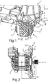
- Fig. 1 is a perspective view of an arrangement 1 shown, which is installed in a washing machine.
- the arrangement 1 comprises a tub 2 and a drive motor 3, which is formed in the embodiment as a BLDC motor.
- the drive motor 3 is connected to the tub 2 via a suspension device 4, which is designed as a 2-point connection.
- the drive motor 3 comprises a housing 5, on which two wings 6 and 7 are integrally formed.
- the tub 2 also includes two rocker seats 8 and 9, with which the wings 6 and 7 can be connected or in Fig. 1 are connected.
- the rocker seats 8 and 9 and / or the wings 6 and 7 may be at least partially formed of plastic.
- the wings 6 and 7 are secured to the rocker seats 8 and 9 by means of screws.
- the drive motor 3 a shaft 10 which has an axis A.
- a perpendicular bisector B of the drive motor 3 in Fig. 1 located.
- the two wings 6 and 7 have a substantially V-position, so that each rocker 6 and 7 with its longitudinal axis C and D has an angle between 30 ° and 60 ° to the bisector B has.
- axes E and F of the rocker receptacles 8 and 9 are not arranged coaxially to the axis A, but in particular parallel thereto. If the axes A, E and F are connected by perpendicular lines, a triangle is formed.
- Fig. 2 is a bottom view of the drive motor 3 is shown. It is thus the viewing direction in the direction of the arrow P in Fig. 1 shown. The non-coaxial but parallel orientation of the axes A, E and F can be seen.
- the wings 6 and 7 are arranged on the housing 5, that they are positioned in the direction of the axis A at the height of a ball bearing 11 of the motor 3. This means that the suspension points are in alignment with the ball bearing 11.
- a connecting line 12 thus extends in the direction of the axis A viewed at the height of the ball bearing 11, wherein the connecting line 12 is shown running as a fictitious connection between the wings 6, 7 and the swing seats 8, 9.
Landscapes
- Engineering & Computer Science (AREA)
- Power Engineering (AREA)
- Textile Engineering (AREA)
- Main Body Construction Of Washing Machines And Laundry Dryers (AREA)
- Detail Structures Of Washing Machines And Dryers (AREA)
Description
- Die Erfindung betrifft eine Anordnung mit einem Laugenbehälter einer Waschmaschine und einem Antriebsmotor, der mit einer Aufhängevorrichtung mit dem Laugenbehälter verbindbar ist, wobei die Aufhängevorrichtung als 2-Punkt-Anbindung ausgebildet ist. Des Weiteren betrifft die Erfindung auch eine Waschmaschine mit einer derartigen Anordnung.
- Aus der
EP 1 424 427 A1 ist eine Waschmaschine bekannt, wobei am Laugenbehälter zwei Fortsätze angebracht sind, an denen vier Fortsätze des Motorgehäuses in der Weise befestigt sind, dass antriebsseitig zwei Paare von Fortsätzen unmittelbar miteinander verbunden werden können. Die beiden übrigen Fortsätze des Motorgehäuses können über ein Zwischenstück mit dem einzigen korrespondierenden Fortsatz am Laugenbehälter verbunden sein, welches Zwischenstück zu den Fortsätzen am Motorgehäuse hinweisende Zapfen trägt und mit einem entgegen der Richtung weisenden Zapfen in einem Loch des laugenbehälterseitigen Fortsatzes lagert. Dieses Zwischenstück trägt zwar zum allgemeinen Toleranzausgleich und zur Schwingungsdämpfung bei. Da es aber auf diese Weise insbesondere beim Schleudergang der Waschmaschine sehr starken Wechselbelastungen ausgesetzt ist, kann es verstärkt zum Bruch des Zwischenstücks kommen, was zum sofortigen Totalausfall der betroffenen Waschmaschine führt. - Des Weiteren ist aus der
EP 1 707 660 A1 eine Anordnung bekannt, bei der an einem Laugenbehälter Arme ausgebildet sind, die zur Aufnahme einer Welle eines Motors vorgesehen sind. Die Welle wird dabei mit einem ersten Ende an dem ersten Arm befestigt, wobei das gegenüberliegende Ende der Welle an dem zweiten Arm befestigt wird. Die Achse der Welle ist daher stets parallel bzw. koaxial zu einer Verbindungsgeraden zwischen den beiden Armen orientiert. Die Anbringung des Motors ist diesbezüglich im Hinblick auf die Zugänglichkeit und Montage unzureichend. Eine derartige 2-Punkt-Anbindung ist daher für die Verschleißarmut des Motors, insbesondere der Welle, nachteilig. - Es ist Aufgabe der vorliegenden Erfindung, eine Anordnung sowie eine Waschmaschine zu schaffen, bei der die 2-Punkt-Anbindung eines Motors an den Laugenbehälter verbessert ist.
- Diese Aufgabe wird durch eine Anordnung und eine Waschmaschine gemäß jeweiligem unabhängigem Patentanspruch gelöst. Bevorzugte und vorteilhafte Ausgestaltungen der Erfindung sind Gegenstände abhängiger Patentansprüche, nachfolgender Beschreibung sowie der Figuren beigefügter Zeichnung, wobei bevorzugten Ausgestaltungen der Anordnung bevorzugte Ausgestaltungen der Waschmaschine entsprechen und umgekehrt, und dies auch dann, wenn es hierin nicht explizit festgestellt ist.
- Bei einer erfindungsgemäßen Anordnung ist demnach vorgesehen, dass diese einen Laugenbehälter einer Waschmaschine und einen Antriebsmotor aufweist. Der Antriebsmotor ist mit dem Laugenbehälter mittels einer Aufhängevorrichtung verbindbar, wobei die Aufhängevorrichtung als 2-Punkt-Anbindung ausgebildet ist. Dies bedeutet, dass die mechanische Befestigung des Antriebsmotors an den Laugenbehälter lediglich nur über zwei Anbindungsstellen erfolgt. An einem Gehäuse des Antriebsmotors sind zwei Schwingen angeordnet, die zur Verbindung mit jeweils einer laugenbehälterseitig angeordneten Schwingenaufnahme ausgebildet sind. Außerdem sind die Schwingen in einem Winkel zu einer Mittelsenkrechten des Antriebsmotors angeordnet sind, insbesondere in einem Winkel zwischen 30° und 60° dazu angeordnet.
- Durch eine derartige Ausgestaltung erfolgt die Anbindung des Antriebsmotors an den Laugenbehälter nicht mehr über eine direkte Befestigung über die Antriebswelle, sondern über von dieser beabstandete und von dieser separate Teile. Die oben genannten Nachteile können dadurch vermieden werden.
- Durch die angewinkelte Stellung der Schwingen kann einerseits ein besonders stabiles mechanisches Konzept realisiert werden, welches darüber hinaus auch kompakt und platzsparend ausgebildet ist. Insbesondere ist somit vorgesehen, dass die beiden Schwingen in einer V-Form angeordnet sind.
- Vorzugsweise sind die drei Achsen parallel zueinander orientiert.
- Im verbundenen Zustand der Schwingen mit den Schwingenaufnahmen sei eine Verbindungsgerade zwischen Achsen der Aufnahmen durch ein Kugellager des Antriebsmotors verlaufend orientiert.
- Vorzugsweise ist diese Verbindungsgerade senkrecht auf der Achse des Kugellagers stehend angeordnet, so dass quasi diese Verbindungsgerade fluchtend mit dem Kugellager angeordnet ist. Dies ist insbesondere dahingehend besonders vorteilhaft, da somit im Hinblick auf die Gewichtsverteilung die Krafteinwirkung bei der Bewegung des Motors auf die Anbindungsstellen minimiert werden kann. Es ist somit auch eine optimierte Motorschwerpunktlage generierbar.
- Vorzugsweise ist vorgesehen, dass die Schwingenaufnahmen zumindest bereichsweise als Kunststoffbuchsen ausgebildet sind. Dadurch kann eine sehr gewichtssparende Ausgestaltung realisiert werden.
- Besonders vorteilhaft ist es, wenn der Laugenbehälter zumindest im Bereich der Schwingenaufnahmen glasfaserverstärkt ist oder duroplastisch ausgebildet ist. Dadurch kann gerade im Bereich der Anbindung ein äußerst stabiler Laugenbehälter ermöglicht werden, der die ganz spezifische 2-Punkt-Anbindung ermöglicht und dauerhaft beibehält.
- Vorzugsweise ist vorgesehen, dass der Antriebsmotor ein BLDC-Motor (Brushless DC-Motor; bürstenloser Gleichstrommotor; auch als PMS-Motor, "PMS" für "Permanent Magnet Synchronous", bezeichnet) ist. Dies ist dahingehend besonders vorteilhaft, da ein derartiger Motor im Vergleich zu anderen Motoren, beispielsweise einem Universalmotor, ein geringeres Gewicht aufweist. Gerade durch eine derartige spezifische Motorart kann somit die 2-Punkt-Anbindung nochmals begünstigt werden.
- Vorzugsweise ist vorgesehen, dass der Antriebsmotor an dem Laugenbehälter angeschraubt ist. Insbesondere mittels eines zusätzlichen Plastikteils kann somit die Befestigung am Laugenbehälter mit Schrauben erfolgen, was insbesondere über die Schwingen und Schwingenaufnahmen erfolgt.
- Durch die erfindungsgemäße Anordnung oder eine ihrer vorteilhaften Ausgestaltungen können nun überflüssige Motorhalterungen am Laugenbehälter entfallen bzw. für andere Funktionen oder Bauteile verwendet werden.
- Ein bevorzugtes Ausführungsbeispiel der Erfindung wird nachfolgend unter Bezugnahme auf die schematischen Figuren in der beigefügten Zeichnung näher erläutert. Es zeigen:
- Fig. 1
- eine perspektivische Darstellung eines Ausführungsbeispiels einer Anordnung mit einem Laugenbehälter und einem Antriebsmotor; und
- Fig. 2
- eine Ansicht von unten auf ein Ausführungsbeispiel des Antriebsmotors der Anordnung gemäß
Fig. 1 . - In den Figuren sind jeweils gleiche oder funktionsgleiche Elemente mit den gleichen Bezugszeichen versehen.
- In
Fig. 1 ist eine perspektivische Darstellung eine Anordnung 1 gezeigt, die in einer Waschmaschine verbaut ist. Die Anordnung 1 umfasst einen Laugenbehälter 2 und einen Antriebsmotor 3, der im Ausführungsbeispiel als BLDC-Motor ausgebildet ist. Der Antriebsmotor 3 ist mit dem Laugenbehälter 2 über eine Aufhängevorrichtung 4, die als 2-Punkt-Anbindung ausgebildet ist, verbunden. Der Antriebsmotor 3 umfasst ein Gehäuse 5, an dem zwei Schwingen 6 und 7 einstückig angeformt sind. - Der Laugenbehälter 2 umfasst darüber hinaus zwei Schwingenaufnahmen 8 und 9, mit denen die Schwingen 6 und 7 verbunden werden können bzw. in
Fig. 1 verbunden sind. Die Schwingenaufnahmen 8 und 9 und/oder die Schwingen 6 und 7 können zumindest teilweise aus Kunststoff ausgebildet sein. Insbesondere ist vorgesehen, dass die Schwingen 6 und 7 an den Schwingenaufnahmen 8 und 9 mittels Schrauben befestigt sind. - Wie darüber hinaus in
Fig. 1 zu erkennen ist, weist der Antriebsmotor 3 eine Welle 10 auf, die eine Achse A besitzt. Vertikal verlaufend zu dieser Achse A ist eine Mittelsenkrechte B des Antriebsmotors 3 inFig. 1 eingezeichnet. Wie zu erkennen ist, weisen die beiden Schwingen 6 und 7 im Wesentlichen eine V-Stellung auf, so dass jede Schwinge 6 und 7 mit ihrer Längsachse C bzw. D einen Winkel zwischen 30° und 60° zur Mittelsenkrechte B aufweist. Zudem ist zu erkennen, dass Achsen E und F der Schwingenaufnahmen 8 und 9 nicht koaxial zur Achse A, insbesondere jedoch parallel dazu angeordnet sind. Werden die Achsen A, E und F jeweils durch senkrecht dazu stehende Geraden verbunden, so wird quasi ein Dreieck gebildet. - In
Fig. 2 ist eine Ansicht von unten auf den Antriebsmotor 3 gezeigt. Es ist somit die Blickrichtung in Richtung des Pfeils P inFig. 1 dargestellt. Die nicht koaxiale jedoch parallele Orientierung der Achsen A, E und F ist zu erkennen. Darüber hinaus ist vorgesehen, dass die Schwingen 6 und 7 derart am Gehäuse 5 angeordnet sind, dass sie in Richtung der Achse A auf Höhe eine Kugellagers 11 des Motors 3 positioniert sind. Dies bedeutet, dass die Aufhängepunkte in Flucht mit dem Kugellager 11 sind. Eine Verbindungsgerade 12 verläuft somit in Richtung der Achse A betrachtet auf Höhe des Kugellagers 11, wobei die Verbindungsgerade 12 als fiktive Verbindung zwischen den Schwingen 6, 7 bzw. den Schwingenaufnahmen 8, 9 verlaufend gezeichnet ist. - Eine besondere Vorteilhaftigkeit ergibt sich bei dieser ganz spezifisch ausgebildeten 2-Punkt-Anbindung in Verbindung mit dem glasfaserverstärkten Laugenbehälter 2 oder einem aus Duroplast zumindest bereichsweise ausgebildeten Laugenbehälter 2 und dem als BLDC-Motor ausgebildeten Antriebsmotor 3.
-
- 1
- Anordnung
- 2
- Laugenbehälter
- 3
- Antriebsmotor
- 4
- Aufhängevorrichtung
- 5
- Gehäuse
- 6, 7
- Schwingen
- 8, 9
- Schwingenaufnahmen
- 10
- Welle
- 11
- Kugellager
- 12
- Verbindungsgerade
Claims (7)
- Anordnung (1) mit einem Laugenbehälter (2) einer Waschmaschine und einem Antriebsmotor (3), der mit einer Aufhängevorrichtung (4) mit dem Laugenbehälter (2) verbindbar ist, wobei die Aufhängevorrichtung (4) als 2-Punktanbindung ausgebildet ist, wobei an einem Gehäuse (5) des Antriebsmotors (3) zwei Schwingen (6, 7) angeordnet sind, die zur Verbindung mit jeweils einer laugenbehälterseitig angeordneten Schwingenaufnahme (8, 9) ausgebildet sind, dadurch gekennzeichnet, dass die Schwingen (6, 7) in Richtung einer Achse (A) einer Welle (10) des Antriebsmotors (3) betrachtet auf Höhe eines Kugellagers (11) des Antriebsmotors (3) angeordnet sind, die Schwingen (6, 7) und das Kugellager (10) in einer Ebene senkrecht zur Achse (A) liegen, und dass die Schwingen (6, 7) in einem Winkel zu einer Mittelsenkrechten (B) des Antriebsmotors (3) angeordnet sind, insbesondere in einem Winkel zwischen 30° und 60° dazu angeordnet sind.
- Anordnung (1) nach Anspruch 1, dadurch gekennzeichnet, dass die Achse (A) der Welle (10) und die zwei Achsen (E, F) der Schwingenaufnahmen parallel zueinander orientiert sind.
- Anordnung (1) nach einem der vorhergehenden Ansprüche, dadurch gekennzeichnet, dass die Schwingenaufnahmen (8, 9) zumindest bereichsweise als Kunststoffbuchsen ausgebildet sind.
- Anordnung (1) nach einem der vorhergehenden Ansprüche, dadurch gekennzeichnet, dass der Laugenbehälter (2) zumindest im Bereich der Schwingenaufnahmen (8, 9) glasfaserverstärkt ist oder duroplastisch ausgebildet ist.
- Anordnung (1) nach einem der vorhergehenden Ansprüche, dadurch gekennzeichnet, dass der Antriebsmotor (3) ein BLDC-Motor ist.
- Anordnung (1) nach einem der vorhergehenden Ansprüche, dadurch gekennzeichnet, dass der Antriebsmotor (3) an dem Laugenbehälter (2) angeschraubt ist.
- Waschmaschine mit einer Anordnung (1) nach einem der vorhergehenden Ansprüche.
Priority Applications (1)
| Application Number | Priority Date | Filing Date | Title |
|---|---|---|---|
| PL12759436T PL2761075T3 (pl) | 2011-09-28 | 2012-09-14 | Układ ze zbiornikiem cieczy pralniczej pralki i z silnikiem napędowym oraz pralka |
Applications Claiming Priority (2)
| Application Number | Priority Date | Filing Date | Title |
|---|---|---|---|
| DE102011083652A DE102011083652A1 (de) | 2011-09-28 | 2011-09-28 | Anordnung mit einem Laugenbehälter einer Waschmaschine und einem Antriebsmotor sowie Waschmaschine |
| PCT/EP2012/068123 WO2013045296A1 (de) | 2011-09-28 | 2012-09-14 | Anordnung mit einem laugenbehälter einer waschmaschine und einem antriebsmotor sowie waschmaschine |
Publications (2)
| Publication Number | Publication Date |
|---|---|
| EP2761075A1 EP2761075A1 (de) | 2014-08-06 |
| EP2761075B1 true EP2761075B1 (de) | 2018-07-04 |
Family
ID=46851992
Family Applications (1)
| Application Number | Title | Priority Date | Filing Date |
|---|---|---|---|
| EP12759436.4A Active EP2761075B1 (de) | 2011-09-28 | 2012-09-14 | Anordnung mit einem laugenbehälter einer waschmaschine und einem antriebsmotor sowie waschmaschine |
Country Status (10)
| Country | Link |
|---|---|
| US (1) | US9951456B2 (de) |
| EP (1) | EP2761075B1 (de) |
| KR (1) | KR101918796B1 (de) |
| CN (1) | CN103842576B (de) |
| DE (1) | DE102011083652A1 (de) |
| ES (1) | ES2682752T3 (de) |
| PL (1) | PL2761075T3 (de) |
| RU (1) | RU2566481C1 (de) |
| TR (1) | TR201811277T4 (de) |
| WO (1) | WO2013045296A1 (de) |
Families Citing this family (3)
| Publication number | Priority date | Publication date | Assignee | Title |
|---|---|---|---|---|
| US9969042B2 (en) | 2013-05-16 | 2018-05-15 | Kreg Enterprises, Inc. | Ratcheting quick-adjust drilling jig |
| KR102418293B1 (ko) * | 2015-03-04 | 2022-07-08 | 삼성전자주식회사 | 드럼 세탁기 |
| US11859334B2 (en) | 2020-12-09 | 2024-01-02 | Samsung Electronics Co., Ltd. | Washing machine |
Family Cites Families (13)
| Publication number | Priority date | Publication date | Assignee | Title |
|---|---|---|---|---|
| DE2126092A1 (de) | 1971-05-21 | 1972-11-30 | Siemens Elektrogeraete Gmbh | Trommelwaschmaschine |
| DE3132211A1 (de) | 1981-08-14 | 1983-03-03 | Licentia Patent-Verwaltungs-Gmbh, 6000 Frankfurt | "trommelwaschmaschine" |
| US4922151A (en) | 1988-08-02 | 1990-05-01 | Emerson Electric Co. | Electric motor mounting assembly |
| EP0750064A1 (de) | 1995-06-24 | 1996-12-27 | Whirlpool Europe B.V. | Befestigungsmethode für den Motor einer Haushaltswaschmaschine und der sich daraus ergebenden Waschmaschine |
| CN2427543Y (zh) | 2000-03-03 | 2001-04-25 | 海尔集团公司 | 电机安装支撑装置 |
| DE10062364A1 (de) * | 2000-12-14 | 2002-06-20 | Bsh Bosch Siemens Hausgeraete | Antriebsvorrichtung für ein Haushaltsgerät und Verfahren zur Montage eines Elektromotors |
| ES2239491B1 (es) | 2002-11-27 | 2006-12-01 | Bsh Electrodomesticos España, S.A. | Sistema de sujecion de motor a cuba en lavadoras. |
| ES2383199T3 (es) | 2005-04-01 | 2012-06-19 | Askoll Holding S.R.L. | Lavadora mejorada y electrodomésticos similares con tambor giratorio |
| US20070063603A1 (en) * | 2005-08-22 | 2007-03-22 | Levine Gregory M | Integrated motor and controller assemblies for horizontal axis washing machines |
| ITMI20070304U1 (it) * | 2007-09-11 | 2009-03-12 | Askoll Holding Srl | Supporto per il fissaggio di un motore elettrico ad una vasca di una lavatrice o simile elettrodomestico |
| JP4966164B2 (ja) * | 2007-11-05 | 2012-07-04 | 株式会社東芝 | 洗濯機 |
| ATE536435T1 (de) * | 2008-07-22 | 2011-12-15 | Bsh Bosch Siemens Hausgeraete | Verfahren zur herstellung eines laugenbehälterteils für eine waschmaschine |
| EP2388365A1 (de) * | 2010-05-19 | 2011-11-23 | Miele & Cie. KG | Trommelwaschmaschine |
-
2011
- 2011-09-28 DE DE102011083652A patent/DE102011083652A1/de not_active Withdrawn
-
2012
- 2012-09-14 KR KR1020147007832A patent/KR101918796B1/ko active Active
- 2012-09-14 TR TR2018/11277T patent/TR201811277T4/tr unknown
- 2012-09-14 US US14/347,814 patent/US9951456B2/en active Active
- 2012-09-14 RU RU2014115283/12A patent/RU2566481C1/ru active
- 2012-09-14 PL PL12759436T patent/PL2761075T3/pl unknown
- 2012-09-14 CN CN201280047532.XA patent/CN103842576B/zh active Active
- 2012-09-14 WO PCT/EP2012/068123 patent/WO2013045296A1/de not_active Ceased
- 2012-09-14 EP EP12759436.4A patent/EP2761075B1/de active Active
- 2012-09-14 ES ES12759436.4T patent/ES2682752T3/es active Active
Non-Patent Citations (1)
| Title |
|---|
| None * |
Also Published As
| Publication number | Publication date |
|---|---|
| CN103842576B (zh) | 2017-07-11 |
| CN103842576A (zh) | 2014-06-04 |
| DE102011083652A1 (de) | 2013-03-28 |
| EP2761075A1 (de) | 2014-08-06 |
| PL2761075T3 (pl) | 2018-12-31 |
| TR201811277T4 (tr) | 2018-08-27 |
| US9951456B2 (en) | 2018-04-24 |
| WO2013045296A1 (de) | 2013-04-04 |
| KR20140072054A (ko) | 2014-06-12 |
| ES2682752T3 (es) | 2018-09-21 |
| KR101918796B1 (ko) | 2018-11-14 |
| US20140305171A1 (en) | 2014-10-16 |
| RU2566481C1 (ru) | 2015-10-27 |
Similar Documents
| Publication | Publication Date | Title |
|---|---|---|
| DE2937961C2 (de) | Vorrichtung zum Verstellen eines Spiegelglasträgers eines Kraftfahrzeugrückspiegels | |
| DE102008058426A1 (de) | Zubehörmontageaufbau | |
| EP1943895A1 (de) | Tragbares Erntegerät | |
| DE102013112776B4 (de) | Servolenkgetriebssystem | |
| EP3149356A1 (de) | Rotationsdämpfer | |
| EP3142884A1 (de) | Aggregatlagerung | |
| EP2655918B1 (de) | Schwingungsdämpfende aufnahmevorrichtung | |
| DE102007013700B4 (de) | Dentalgeräterüttelvorrichtung | |
| EP1856417B1 (de) | Hochlastbeschlag zum verbinden von zwei bauteilen | |
| WO2013045296A1 (de) | Anordnung mit einem laugenbehälter einer waschmaschine und einem antriebsmotor sowie waschmaschine | |
| DE102010048858A1 (de) | Vorderachsträger mit Anordnung eines Lenkgetriebes und eines Vorderachsstabilisators | |
| EP2377729A1 (de) | Vorrichtung zur Befestigung eines Überrollbügels oder dergleichen Anbauteiles an einem Fahrzeug | |
| EP2734751B1 (de) | Verfahren zum fügen von getriebebauteilen | |
| EP1963559B1 (de) | Befestigungsvorrichtung für einen motor in einem haushaltgerät | |
| DE102014109474B4 (de) | Stoßfängerträgervorrichtung für ein Fahrzeug | |
| DE102012011048B4 (de) | Scharniervorrichtung und eine Türanlage mit der Scharniervorrichtung | |
| DE202022102147U1 (de) | Elastisches Lager zum Abstützen eines Bauteils an einem horizontal verlaufenden Rand eines Befestigungslochs | |
| DE102004001286B4 (de) | Vorrichtung zur Halterung eines Bauteils an einer Karosserie | |
| WO2012119851A1 (de) | Anordnung aus einem laugenbehälter einer haushaltwaschmaschine und einem antriebsmotor | |
| WO2015036217A1 (de) | Spannvorrichtung für einer kraftrad kette | |
| EP1719925B1 (de) | Befestigungssystem für längliche, quersteife Verbindungselemente | |
| DE102016005334B4 (de) | Schiffchenantriebsstrang für eine Schiffchenstickmaschine und Schiffchenstickmaschine | |
| EP2551431B1 (de) | Kompaktes Türband für den verdeckten Einbau | |
| AT513028A4 (de) | Einspritzpumpe mit Fliehkraftregler | |
| WO2011079991A2 (de) | Steckverbindung mit erhöhter schwingfestigkeit |
Legal Events
| Date | Code | Title | Description |
|---|---|---|---|
| PUAI | Public reference made under article 153(3) epc to a published international application that has entered the european phase |
Free format text: ORIGINAL CODE: 0009012 |
|
| 17P | Request for examination filed |
Effective date: 20140428 |
|
| AK | Designated contracting states |
Kind code of ref document: A1 Designated state(s): AL AT BE BG CH CY CZ DE DK EE ES FI FR GB GR HR HU IE IS IT LI LT LU LV MC MK MT NL NO PL PT RO RS SE SI SK SM TR |
|
| DAX | Request for extension of the european patent (deleted) | ||
| RAP1 | Party data changed (applicant data changed or rights of an application transferred) |
Owner name: BSH HAUSGERAETE GMBH |
|
| 17Q | First examination report despatched |
Effective date: 20150723 |
|
| REG | Reference to a national code |
Ref country code: DE Ref legal event code: R079 Ref document number: 502012012992 Country of ref document: DE Free format text: PREVIOUS MAIN CLASS: D06F0037200000 Ipc: H02K0005040000 |
|
| GRAP | Despatch of communication of intention to grant a patent |
Free format text: ORIGINAL CODE: EPIDOSNIGR1 |
|
| RIC1 | Information provided on ipc code assigned before grant |
Ipc: D06F 37/20 20060101ALI20180131BHEP Ipc: H02K 5/04 20060101AFI20180131BHEP Ipc: H02K 5/26 20060101ALI20180131BHEP |
|
| INTG | Intention to grant announced |
Effective date: 20180226 |
|
| GRAS | Grant fee paid |
Free format text: ORIGINAL CODE: EPIDOSNIGR3 |
|
| GRAA | (expected) grant |
Free format text: ORIGINAL CODE: 0009210 |
|
| AK | Designated contracting states |
Kind code of ref document: B1 Designated state(s): AL AT BE BG CH CY CZ DE DK EE ES FI FR GB GR HR HU IE IS IT LI LT LU LV MC MK MT NL NO PL PT RO RS SE SI SK SM TR |
|
| REG | Reference to a national code |
Ref country code: GB Ref legal event code: FG4D Free format text: NOT ENGLISH |
|
| REG | Reference to a national code |
Ref country code: CH Ref legal event code: EP |
|
| REG | Reference to a national code |
Ref country code: AT Ref legal event code: REF Ref document number: 1015562 Country of ref document: AT Kind code of ref document: T Effective date: 20180715 |
|
| REG | Reference to a national code |
Ref country code: IE Ref legal event code: FG4D Free format text: LANGUAGE OF EP DOCUMENT: GERMAN |
|
| REG | Reference to a national code |
Ref country code: DE Ref legal event code: R096 Ref document number: 502012012992 Country of ref document: DE |
|
| REG | Reference to a national code |
Ref country code: ES Ref legal event code: FG2A Ref document number: 2682752 Country of ref document: ES Kind code of ref document: T3 Effective date: 20180921 |
|
| REG | Reference to a national code |
Ref country code: NL Ref legal event code: MP Effective date: 20180704 |
|
| REG | Reference to a national code |
Ref country code: LT Ref legal event code: MG4D |
|
| PG25 | Lapsed in a contracting state [announced via postgrant information from national office to epo] |
Ref country code: NL Free format text: LAPSE BECAUSE OF FAILURE TO SUBMIT A TRANSLATION OF THE DESCRIPTION OR TO PAY THE FEE WITHIN THE PRESCRIBED TIME-LIMIT Effective date: 20180704 |
|
| PG25 | Lapsed in a contracting state [announced via postgrant information from national office to epo] |
Ref country code: LT Free format text: LAPSE BECAUSE OF FAILURE TO SUBMIT A TRANSLATION OF THE DESCRIPTION OR TO PAY THE FEE WITHIN THE PRESCRIBED TIME-LIMIT Effective date: 20180704 Ref country code: BG Free format text: LAPSE BECAUSE OF FAILURE TO SUBMIT A TRANSLATION OF THE DESCRIPTION OR TO PAY THE FEE WITHIN THE PRESCRIBED TIME-LIMIT Effective date: 20181004 Ref country code: CZ Free format text: LAPSE BECAUSE OF FAILURE TO SUBMIT A TRANSLATION OF THE DESCRIPTION OR TO PAY THE FEE WITHIN THE PRESCRIBED TIME-LIMIT Effective date: 20180704 Ref country code: NO Free format text: LAPSE BECAUSE OF FAILURE TO SUBMIT A TRANSLATION OF THE DESCRIPTION OR TO PAY THE FEE WITHIN THE PRESCRIBED TIME-LIMIT Effective date: 20181004 Ref country code: SE Free format text: LAPSE BECAUSE OF FAILURE TO SUBMIT A TRANSLATION OF THE DESCRIPTION OR TO PAY THE FEE WITHIN THE PRESCRIBED TIME-LIMIT Effective date: 20180704 Ref country code: GR Free format text: LAPSE BECAUSE OF FAILURE TO SUBMIT A TRANSLATION OF THE DESCRIPTION OR TO PAY THE FEE WITHIN THE PRESCRIBED TIME-LIMIT Effective date: 20181005 Ref country code: IS Free format text: LAPSE BECAUSE OF FAILURE TO SUBMIT A TRANSLATION OF THE DESCRIPTION OR TO PAY THE FEE WITHIN THE PRESCRIBED TIME-LIMIT Effective date: 20181104 Ref country code: RS Free format text: LAPSE BECAUSE OF FAILURE TO SUBMIT A TRANSLATION OF THE DESCRIPTION OR TO PAY THE FEE WITHIN THE PRESCRIBED TIME-LIMIT Effective date: 20180704 Ref country code: FI Free format text: LAPSE BECAUSE OF FAILURE TO SUBMIT A TRANSLATION OF THE DESCRIPTION OR TO PAY THE FEE WITHIN THE PRESCRIBED TIME-LIMIT Effective date: 20180704 |
|
| PG25 | Lapsed in a contracting state [announced via postgrant information from national office to epo] |
Ref country code: LV Free format text: LAPSE BECAUSE OF FAILURE TO SUBMIT A TRANSLATION OF THE DESCRIPTION OR TO PAY THE FEE WITHIN THE PRESCRIBED TIME-LIMIT Effective date: 20180704 Ref country code: AL Free format text: LAPSE BECAUSE OF FAILURE TO SUBMIT A TRANSLATION OF THE DESCRIPTION OR TO PAY THE FEE WITHIN THE PRESCRIBED TIME-LIMIT Effective date: 20180704 Ref country code: HR Free format text: LAPSE BECAUSE OF FAILURE TO SUBMIT A TRANSLATION OF THE DESCRIPTION OR TO PAY THE FEE WITHIN THE PRESCRIBED TIME-LIMIT Effective date: 20180704 |
|
| REG | Reference to a national code |
Ref country code: DE Ref legal event code: R097 Ref document number: 502012012992 Country of ref document: DE |
|
| PG25 | Lapsed in a contracting state [announced via postgrant information from national office to epo] |
Ref country code: MC Free format text: LAPSE BECAUSE OF FAILURE TO SUBMIT A TRANSLATION OF THE DESCRIPTION OR TO PAY THE FEE WITHIN THE PRESCRIBED TIME-LIMIT Effective date: 20180704 Ref country code: IT Free format text: LAPSE BECAUSE OF FAILURE TO SUBMIT A TRANSLATION OF THE DESCRIPTION OR TO PAY THE FEE WITHIN THE PRESCRIBED TIME-LIMIT Effective date: 20180704 Ref country code: EE Free format text: LAPSE BECAUSE OF FAILURE TO SUBMIT A TRANSLATION OF THE DESCRIPTION OR TO PAY THE FEE WITHIN THE PRESCRIBED TIME-LIMIT Effective date: 20180704 Ref country code: RO Free format text: LAPSE BECAUSE OF FAILURE TO SUBMIT A TRANSLATION OF THE DESCRIPTION OR TO PAY THE FEE WITHIN THE PRESCRIBED TIME-LIMIT Effective date: 20180704 |
|
| REG | Reference to a national code |
Ref country code: CH Ref legal event code: PL |
|
| PLBE | No opposition filed within time limit |
Free format text: ORIGINAL CODE: 0009261 |
|
| STAA | Information on the status of an ep patent application or granted ep patent |
Free format text: STATUS: NO OPPOSITION FILED WITHIN TIME LIMIT |
|
| PG25 | Lapsed in a contracting state [announced via postgrant information from national office to epo] |
Ref country code: DK Free format text: LAPSE BECAUSE OF FAILURE TO SUBMIT A TRANSLATION OF THE DESCRIPTION OR TO PAY THE FEE WITHIN THE PRESCRIBED TIME-LIMIT Effective date: 20180704 Ref country code: SM Free format text: LAPSE BECAUSE OF FAILURE TO SUBMIT A TRANSLATION OF THE DESCRIPTION OR TO PAY THE FEE WITHIN THE PRESCRIBED TIME-LIMIT Effective date: 20180704 Ref country code: SK Free format text: LAPSE BECAUSE OF FAILURE TO SUBMIT A TRANSLATION OF THE DESCRIPTION OR TO PAY THE FEE WITHIN THE PRESCRIBED TIME-LIMIT Effective date: 20180704 |
|
| 26N | No opposition filed |
Effective date: 20190405 |
|
| REG | Reference to a national code |
Ref country code: BE Ref legal event code: MM Effective date: 20180930 |
|
| REG | Reference to a national code |
Ref country code: IE Ref legal event code: MM4A |
|
| PG25 | Lapsed in a contracting state [announced via postgrant information from national office to epo] |
Ref country code: LU Free format text: LAPSE BECAUSE OF NON-PAYMENT OF DUE FEES Effective date: 20180914 |
|
| PG25 | Lapsed in a contracting state [announced via postgrant information from national office to epo] |
Ref country code: IE Free format text: LAPSE BECAUSE OF NON-PAYMENT OF DUE FEES Effective date: 20180914 |
|
| PG25 | Lapsed in a contracting state [announced via postgrant information from national office to epo] |
Ref country code: BE Free format text: LAPSE BECAUSE OF NON-PAYMENT OF DUE FEES Effective date: 20180930 Ref country code: CH Free format text: LAPSE BECAUSE OF NON-PAYMENT OF DUE FEES Effective date: 20180930 Ref country code: FR Free format text: LAPSE BECAUSE OF NON-PAYMENT OF DUE FEES Effective date: 20180930 Ref country code: LI Free format text: LAPSE BECAUSE OF NON-PAYMENT OF DUE FEES Effective date: 20180930 Ref country code: SI Free format text: LAPSE BECAUSE OF FAILURE TO SUBMIT A TRANSLATION OF THE DESCRIPTION OR TO PAY THE FEE WITHIN THE PRESCRIBED TIME-LIMIT Effective date: 20180704 |
|
| REG | Reference to a national code |
Ref country code: AT Ref legal event code: MM01 Ref document number: 1015562 Country of ref document: AT Kind code of ref document: T Effective date: 20180914 |
|
| PG25 | Lapsed in a contracting state [announced via postgrant information from national office to epo] |
Ref country code: MT Free format text: LAPSE BECAUSE OF FAILURE TO SUBMIT A TRANSLATION OF THE DESCRIPTION OR TO PAY THE FEE WITHIN THE PRESCRIBED TIME-LIMIT Effective date: 20180704 Ref country code: AT Free format text: LAPSE BECAUSE OF NON-PAYMENT OF DUE FEES Effective date: 20180914 |
|
| PG25 | Lapsed in a contracting state [announced via postgrant information from national office to epo] |
Ref country code: PT Free format text: LAPSE BECAUSE OF FAILURE TO SUBMIT A TRANSLATION OF THE DESCRIPTION OR TO PAY THE FEE WITHIN THE PRESCRIBED TIME-LIMIT Effective date: 20180704 Ref country code: HU Free format text: LAPSE BECAUSE OF FAILURE TO SUBMIT A TRANSLATION OF THE DESCRIPTION OR TO PAY THE FEE WITHIN THE PRESCRIBED TIME-LIMIT; INVALID AB INITIO Effective date: 20120914 |
|
| PG25 | Lapsed in a contracting state [announced via postgrant information from national office to epo] |
Ref country code: CY Free format text: LAPSE BECAUSE OF FAILURE TO SUBMIT A TRANSLATION OF THE DESCRIPTION OR TO PAY THE FEE WITHIN THE PRESCRIBED TIME-LIMIT Effective date: 20180704 Ref country code: MK Free format text: LAPSE BECAUSE OF NON-PAYMENT OF DUE FEES Effective date: 20180704 |
|
| PGFP | Annual fee paid to national office [announced via postgrant information from national office to epo] |
Ref country code: GB Payment date: 20220927 Year of fee payment: 11 |
|
| PGFP | Annual fee paid to national office [announced via postgrant information from national office to epo] |
Ref country code: ES Payment date: 20221018 Year of fee payment: 11 |
|
| REG | Reference to a national code |
Ref country code: DE Ref legal event code: R084 Ref document number: 502012012992 Country of ref document: DE |
|
| GBPC | Gb: european patent ceased through non-payment of renewal fee |
Effective date: 20230914 |
|
| PG25 | Lapsed in a contracting state [announced via postgrant information from national office to epo] |
Ref country code: GB Free format text: LAPSE BECAUSE OF NON-PAYMENT OF DUE FEES Effective date: 20230914 |
|
| PG25 | Lapsed in a contracting state [announced via postgrant information from national office to epo] |
Ref country code: GB Free format text: LAPSE BECAUSE OF NON-PAYMENT OF DUE FEES Effective date: 20230914 |
|
| REG | Reference to a national code |
Ref country code: ES Ref legal event code: FD2A Effective date: 20241029 |
|
| PG25 | Lapsed in a contracting state [announced via postgrant information from national office to epo] |
Ref country code: ES Free format text: LAPSE BECAUSE OF NON-PAYMENT OF DUE FEES Effective date: 20230915 |
|
| PG25 | Lapsed in a contracting state [announced via postgrant information from national office to epo] |
Ref country code: ES Free format text: LAPSE BECAUSE OF NON-PAYMENT OF DUE FEES Effective date: 20230915 |
|
| PGFP | Annual fee paid to national office [announced via postgrant information from national office to epo] |
Ref country code: DE Payment date: 20250930 Year of fee payment: 14 |
|
| PGFP | Annual fee paid to national office [announced via postgrant information from national office to epo] |
Ref country code: PL Payment date: 20250829 Year of fee payment: 14 Ref country code: TR Payment date: 20250909 Year of fee payment: 14 |