EP2761069B1 - Tissu de séchage à traversée d'air semi-recto-verso à dix foules - Google Patents
Tissu de séchage à traversée d'air semi-recto-verso à dix foules Download PDFInfo
- Publication number
- EP2761069B1 EP2761069B1 EP12835839.7A EP12835839A EP2761069B1 EP 2761069 B1 EP2761069 B1 EP 2761069B1 EP 12835839 A EP12835839 A EP 12835839A EP 2761069 B1 EP2761069 B1 EP 2761069B1
- Authority
- EP
- European Patent Office
- Prior art keywords
- fabric
- pockets
- warp
- weft
- yarns
- Prior art date
- Legal status (The legal status is an assumption and is not a legal conclusion. Google has not performed a legal analysis and makes no representation as to the accuracy of the status listed.)
- Active
Links
Images


Classifications
-
- D—TEXTILES; PAPER
- D21—PAPER-MAKING; PRODUCTION OF CELLULOSE
- D21F—PAPER-MAKING MACHINES; METHODS OF PRODUCING PAPER THEREON
- D21F1/00—Wet end of machines for making continuous webs of paper
- D21F1/0027—Screen-cloths
-
- D—TEXTILES; PAPER
- D21—PAPER-MAKING; PRODUCTION OF CELLULOSE
- D21F—PAPER-MAKING MACHINES; METHODS OF PRODUCING PAPER THEREON
- D21F7/00—Other details of machines for making continuous webs of paper
- D21F7/08—Felts
- D21F7/12—Drying
-
- D—TEXTILES; PAPER
- D03—WEAVING
- D03D—WOVEN FABRICS; METHODS OF WEAVING; LOOMS
- D03D11/00—Double or multi-ply fabrics not otherwise provided for
- D03D11/02—Fabrics formed with pockets, tubes, loops, folds, tucks or flaps
Definitions
- the present invention concerns papermaker's fabrics which can be used to develop and augment caliper and bulk in paper products formed thereon. It is particularly concerned with such fabrics that are designed and arranged to provide a plurality of machine direction oriented pockets on their paper conveying surface into which the paper product is deflected as it is conveyed through a through-air drying (TAD) unit in a tissue manufacturing process. It is more particularly concerned with such fabrics which are woven according to a 10-shed, semi-duplex design which provides for pockets of two differing sizes in the paper side surface of the fabric.
- TAD through-air drying
- a headbox directs a dilute slurry of papermaking fibers and water (known as the "stock") onto a moving forming fabric from which it is subsequently transferred downstream as a very wet web onto a though-air dryer (TAD) fabric.
- the web together with the fabric pass through a through-air dryer arrangement where the web is molded and dried.
- the TAD fabric will ideally impart a surface topography to the eventual sheet which topography can be provided by a combination of recesses, or pockets in the otherwise generally planar PS fabric surface of the fabric, and protrusions, or knuckles, which extend above the fabric plane.
- the pockets create areas of high fiber concentration in the sheet, while the protrusions form regions of relatively lower fiber concentration; together, the zones of high and low fiber concentration impart desirable softness and absorbency characteristics to the sheet thus formed.
- Such fabrics are well known and numerous constructions have been described in the prior art.
- the known fabrics are of either single or multiple layer construction, and are designed to impart a pattern onto the paper sheet which they convey so as to create the aforementioned desirable properties.
- These known fabrics deliver surface topography using various means, such as by providing a patterned, resin coated surface onto a woven substrate in the manner described for example by Trokhan et al. in US 5,275,700 and others; introducing surface sculpting yarns into the fabric surface as described by Chiu et al.
- each warp yarn knuckle may pass over 6 consecutive weft yarns, three of which define one of the 4 sides of a first pocket, the remaining three forming one of the four sides of a second pocket.
- Each weft yarn knuckle may pass under one of the warp yarn knuckle borders and over the other warp yarn knuckle border.
- Fabrics woven according to then '493 patent are of single layer construction (i.e. there is one set of warp yarns which are mutually coplanar), and exhibit longitudinally oriented pockets whose bottoms are formed by a single warp yarn and two weft yarns resulting in the pocket bottom being raised in a T-shape.
- TAD fabric in which pockets having at least two differing sizes are created such that the tissue sheet formed thereon exhibits protrusions of at least two differing sizes and shapes.
- Such sheets may provide enhanced tactile softness as well as other physical and mechanical properties as would be desirable by the consumer.
- the present invention provides a woven, single layer, through-air dryer (TAD) fabric, which fabric is woven according to a repeat pattern to provide a fabric having first and second opposing and generally planar surfaces, a machine direction and a cross-machine direction which directions are mutually perpendicular and coplanar with the first and second surfaces, wherein in the pattern repeat, warp and weft yarns are interwoven to provide a plurality of warp and weft yarn knuckles which together comprise the generally planar fabric surfaces and, between two adjacent pairs of warp and weft yarn knuckles on at least a first fabric surface, pockets having an area that is defined by the pairs of warp yarn knuckles and weft yarn knuckles and a depth which is recessed below the first planar surface, wherein in each repeat of the pattern:
- the weave is a 10 shed pattern requiring 10 warp yarns and 10 weft yarns in each repeat.
- the fabric is symmetrical such that the repeating pattern provided to the first and second generally planar surfaces is identical.
- the repeating pattern provided to each of the first and second planar surfaces is not identical and the fabric is not symmetrical.
- alternate warp yarns appear predominantly on only one of the two generally planar fabric surfaces. More preferably, alternate warp yarns are arranged so as to provide warp yarn knuckles to one of the two fabric surfaces.
- the weave provides a semi-duplex construction wherein the warp yarns form two apparent planes in the fabric and the warp yarns are not stacked in vertical relation one over the other.
- the warp yarn knuckles float over at least 4 weft yarns on a first of the two fabric surfaces.
- the warp yarn knuckles float over up to 9 weft yarns.
- each of the warp yarn knuckles forms the MD sides of four pockets. More preferably, the warp yarn knuckles form the MD sides of two first pockets and two second pockets which are mutually adjacent to one another.
- the first and second pockets are separated in the MD by one weft yarn knuckle.
- the weft yarn knuckles float over three warp yarns on one of the two fabric surfaces.
- each pocket is separated in the CD from the adjacent pocket by one warp yarn.
- Each pocket is preferably separated in the MD from the adjacent pocket by one weft yarn. More preferably, each pocket is separated from an adjacent pocket by one warp and one weft yarn knuckle.
- each pocket is defined by two warp yarn knuckles and two weft yarn knuckles.
- Each warp yarn knuckle is separated in the CD from an adjacent warp yarn knuckle on the same fabric surface by one warp yarn.
- the warp yarns are arranged so as to form knuckles on at least one of the two fabric surfaces; in one preferred design (e.g. Figure 1 ) 50% of the warp yarns float over 8 weft yarns in one repeat of the weave pattern so as to form two warp yarn knuckles on one of the two fabric surfaces, each knuckle of which floats over 4 consecutive weft yarns. In another preferred design, (e.g. Figure 6 ) the warp yarns float over 9 consecutive weft yarns in one repeat of the weave pattern so as to form one warp yarn knuckle on one of the fabric surfaces. Other designs with different warp knuckle float lengths are possible. In both preferred embodiments, only 50% of the warp yarns in one repeat of the weave pattern form knuckles on one surface of the fabric.
- one preferred design e.g. Figure 1
- 50% of the warp yarns float over 8 weft yarns in one repeat of the weave pattern so as to form two
- the invention provides a single layer fabric woven from a system of warp yarns and a system of weft yarns to define first and second generally planar surfaces corresponding to a paper support surface and a machine side surface.
- the warp and weft yarns are interwoven to provide a plurality of warp and weft yarn knuckles forming the first generally planar fabric surface, and pockets are defined between two adjacent pairs of warp and weft yarn knuckles on each of the first and second generally planar surfaces.
- the pockets having an area that is defined by the pairs of warp and weft yarn knuckles and a depth which is recessed below the first planar surface.
- the warp yarn knuckles that form the sides of the pockets float over from 4 to 9 weft yearns, and the weft yarn knuckles that form remaining sides of the pockets float over 3 warp yarns on each of the paper support and machine side surfaces.
- each of the fabric surfaces includes pockets of two different sizes.
- each of the warp yarn knuckles forms the sides of 4 pockets.
- Each of the weft yarn knuckles preferably also forms the sides of 4 pockets. More preferably, the pockets on each surface of the fabric are separated from adjacent pockets by a single yarn in each direction.
- opposite corners of each of the pockets are formed by the warp yarn knuckles, and other opposite corners formed by the weft yarn knuckles
- the warp and weft yarn knuckles together define at least the first planar surface of the fabrics.
- the pockets formed between the knuckles have a surface area whose perimeter is defined by two warp and two weft yarn knuckles.
- the bottom surface area of each pocket is defined by one warp yarn and at least one weft yarn, both of which are recessed below the first planar surface.
- Each pocket has a pocket depth that is between 50% and 100% of the diameter, or thickness, of the warp yarns.
- the fabric may be woven using either circular cross-section monofilaments or flat (rectangular cross-section) warp yarns whose aspect ratio (ratio of width to height) is 1.4:1 or greater. If circular cross-section yarns are used, the fabric may require a mechanical surface treatment such as by abrasion (sanding) to provide a desired contact area of at least about 14%, and preferably at least 20%, or more. Alternatively, generally rectangular monofilaments may be used, in which case fabric surfacing (e.g. by abrasion) may not be necessary, or is at least significantly reduced. However, these fabrics are typically sanded to increase contact area between fabric and sheet and thus improve various properties relating to sheet transport in a TAD process, or sheet release in the forming process.
- abrasion e.g. by abrasion
- the weft yarns used in the fabrics of the invention may be of circular or generally rectangular cross-sectional shape; circular is preferred.
- the diameter of the circular weft yarns will be in the range of from about 0.30mm to about 0.80mm. Selection of appropriate weft yarn diameter will be dictated by the end use requirements of the fabric as they will have a significant effect on certain of the performance characteristics of the fabric, such as air permeability.
- the component monofilaments are ideally comprised of a polyester such as PET which has been stabilized to retard hydrolytic degradation due to the heat and humidity encountered in the sheet product process; alternatively, the yarns are comprised of a polymer such as PPS, PEEK or the like which are inherently resistant to such degradation.
- the fabric may be coated with a surface treatment prior to or during use with a nanoparticle coating such as described in US 7,811,627 to Baker et al.
- the fabric is heat-set according to known techniques so as to structurally stabilize it against deformation.
- a suitable seam is then installed in the resulting fabric; the seam is typically a woven-in seam in which a portion of the weft yarns are removed adjacent the fabric ends, the warp ends are freed at these locations, and the free warp yarns are then rewoven back into the corresponding opposing paths according to techniques known in the art.
- the thus formed seam may be reinforced by laser welding, ultrasonic bonding, or application of a suitable adhesive at or proximate to the warp terminations. Alternatively, a pin seam or other suitable seam construction may be installed, depending on need.
- the completed fabric is then ready for installation in either the forming or through-air dryer section of a papermaking machine.
- machine direction refers to a direction in the papermaking machine that is from the headbox towards the dryer section;
- cross-machine direction or CD, is a direction that is perpendicular to and coplanar with the MD.
- warp yarns are normally oriented generally in the MD, while the weft yarns are normally oriented in the CD when the fabric is in use.
- the woven fabric has two coplanar surfaces: one is the machine side (MS) which is that surface which, when in use, will be in contact with rolls and stationary elements in the machine for which it is intended; the second is the paper side (PS) upon which the product will be formed and conveyed. Additionally, the terms “a” and “one” are defined as including one or more of the referenced item unless specifically noted.
- MS machine side
- PS paper side
- the warp and weft yarn knuckles define the exterior boundary of at least one of these surfaces, in particular the PS.
- a warp or weft yarn "knuckle” is a localized deformation caused by a first yarn bending over or around one or more second yarns oriented perpendicularly to and interwoven with the first so as to "float" over and be supported by the second yarns.
- the related term "float length" refers to the number of second yarns over which a selected first yarn floats.
- a "knuckle” is a portion of a yarn which, in the woven fabric, is raised a small amount above the general fabric plane as it floats over certain other yarns and defines at least the first planar surface of the fabric
- a "pocket” is an area in the first planar surface whose perimeter is defined by two warp and two weft yarn knuckles and whose interior surface is recessed below the exterior boundary of the PS.
- the "open area" of a pocket is therefore the length x the width of the pocket.
- the pockets in the fabric surface create small, localized "pillows" of relatively higher fiber density in the thus formed sheet; the warp and weft yarn knuckles of the fabric surface are localized protrusions above the general fabric plane which produce areas of relatively lower fiber density in the product. Together, the knuckles and pockets in the fabric surface impart bulk and other important mechanical properties to the paper sheet to enhance its utility for use as a tissue or towel product.
- Figure 1 is a weave diagram of a unit cell or pattern square of a first embodiment of a fabric that is woven in accordance with the teaching of the present invention; the weave diagram provides the weaving, or interlacing, pattern of the warp and weft yarns in one repeat of the fabric weave.
- the warp yarns are numbered from 1 to 10 across the top of the diagram, while the weft yarns are numbered from 1 to 10 along the left side.
- a black square indicates that a warp yarn is above a weft yarn
- a white square indicates that the warp yarn is below a weft yarn at the selected location.
- the unit cell of Figure 1 represents one repeat of the weave pattern which is duplicated across the width and the length of the entire fabric.
- the weave pattern requires 10 sheds in the loom to control the position of the warp yarns, and the pattern repeats over 10 weft, such that an eleventh (11 th ) weft yarn will follow the same interlacing pattern as that shown for weft number 1 at the top of the diagram.
- warp yarn 1 passes over weft yarn 1, under weft yarns 2, 3, 4 and 5, over weft yarn 6, and then under weft yarns 7 through 10; at this point, the path of warp yarn 1 repeats the illustrated pattern beginning from weft yarn 1.
- the adjacent warp yarn 2 also passes over weft yarn 1, then under weft yarn 2, over weft yarns 3 to 6, under weft yarn 7, and then over weft yarns 8 to 10 to complete the pattern.
- Warp yarns 3, 5, 7 and 9 follow similar paths to that of warp 1, but are offset relative to each other by two weft (i.e. the path of warp 1 is repeated, but commences as if shifted down in the pattern by two weft).
- Warp yarns 4, 6, 8 and 10 follow similar paths to that of warp 2, but are also offset, or shifted, by two weft yarns in the pattern. Because of the alternation of similar warp paths by every second warp yarn, the fabric of Figure 1 is symmetric and, in the woven cloth, both opposing planar surfaces are essentially identical. It will also be appreciated that it is only every second warp yarn in the pattern, i.e.
- warp yarns 2, 4, 6, 8 and 10 which form knuckles on the PS of the fabric as it is only these warp yarns which are "up” as indicated by the black squares in the pattern.
- Warp yarns 1, 3, 5, 7 and 9 are passed over by the weft yarns in this pattern (as indicated by the white squares) and thus appear on the opposite MS surface of the fabric.
- Figure 2 shows this arrangement more clearly.
- Figure 2 is a photograph of the PS (paper side) surface of a fabric 10 woven according to the weave pattern design shown in Figure 1 ; this is the fabric surface which would, when in use, be used to convey the paper product that is to be produced using the fabric. However, because of the symmetrical nature of this fabric design, either the PS or the opposing MS (machine side) surface could be used for this purpose.
- the weft yarns 100 are oriented from left to right across the page, while the warp yarns 200 are oriented vertically down the page.
- the warp and weft yarn knuckles in the PS surface of the fabric as shown in Figure 2 have been surfaced (mechanically abraded) so as to increase the surface contact area of the fabric, the result of which appears as ovals in the weft yarn knuckles such as at 150 and the warp yarns as at 250.
- Examination of the fabric surface shown in Figure 2 in conjunction with the weave diagram of Figure 1 shows that only every second warp yarn forms a warp yarn knuckle such as 260 in this surface (shown in black in Figure 2 ).
- the alternate warp yarns, which are not colored, lie below the plane of the warp yarn knuckles formed by every second warp yarn and serve to form the bottom of the pockets created in the fabric surface by the weave pattern.
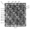
- Figure 3 presents a photograph of the fabric 10 shown in Figure 2 with a unit cell 300 superimposed on the PS surface of the fabric to clearly indicate one full repeat of the weave pattern (i.e. the weave diagram of Figure 1 ).
- Figure 3 also shows in outline the fabric pockets provided by the weave pattern in one unit cell or repeat. Inspection of Figure 3 shows that there are 20 pockets in the unit cell 300; the pockets are of two differing sizes and each is outlined on the fabric surface using a solid line for the larger pockets (denoted by the numeral 1 inside a representative large pocket area 310) and a dashed line for the smaller pockets (denoted by the corresponding numeral 2 inside representative smaller pocket 320).
- the first pockets such as at 310, 330,350 and 370 are "larger" pockets, meaning they have a larger open surface area than the second pockets, such as at 320, 340 and 360 which are smaller in relation to the first pockets.
- Warp yarn knuckles 210 and 240 Inspection of a larger pocket such as 310 shows that it is bordered by two warp yarn knuckles 210 and 240, and two weft yarn knuckles 110 and 120.
- the warp yarn knuckles 210 and 240 each "float", or pass over, four consecutive weft yarns on each MD side of the pocket 310.
- Warp yarn knuckle 240 is "bounded" at the upper end of pocket 310 by the knuckle formed by weft 110, and at the lower end by the knuckle formed by weft 130. It can also be seen that warp yarn knuckle 240 forms a common MD border for both large pocket 310 and adjacent small pocket 320, as well as small pocket 360 and large pocket 370.
- weft yarn knuckle 110 forms the top boundary of large pocket 310 where it floats over three warp in succession from left to right, while also forming the top boundary of the adjacent (right) small pocket 360. It can also be seen that weft yarn knuckle 110 also forms the bottom perimeter of small pocket 340 and large pocket 350.
- small pocket 320 is bounded on top by weft yarn knuckle 120, which also forms the bottom perimeter of large pocket 310; weft yarn knuckle 130 forms the bottom boundary of small pocket 320 and adjacent large pocket 370; warp yarn knuckles 230 and 240 form the left and right sides respectively of small pocket 320.
- Warp yarn knuckle 230 also forms the left boundary of large pocket 330 which is bounded by weft knuckle 130 at the top; the pattern continues in the manner just described throughout the fabric.
- Figure 3 thus shows a fabric woven according to the 10-shed pattern of Figure 1 which provides for 20 pockets of two differing sizes in each unit cell measuring 10 warp by 10 weft in a fabric of the invention.
- Each pocket is bounded by warp yarn knuckles which float over 4 weft yarns to form lateral MD sides of both the large pockets such as 310 and small pockets such as 320.
- Each pocket is also bounded by weft yarn knuckles of two weft yarns each of which forms a float as they pass over three warp yarns.
- Comparison of Figure 3 with the weave pattern of Figure 1 clearly shows this float pattern.
- the interior open areas of the large pockets such as 310 each include 2 weft yarns and one warp yarn; the interior open areas of small pockets such as 320 are formed by one warp yarn and one weft yarn.
- the large pockets such as 310 thus have a length of two weft and width of one warp yarn; the small pockets such as 320 have a length and width of one weft and warp yarn.
- each of the first and second pockets is bounded by two warp yarn knuckles and two weft yarn knuckles which are arranged such that:
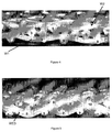
- Figure 4 shows, in cross section across the weft yarns and along a warp yarn, one full repeat of the weave pattern shown in Figure 1 .
- the paths of warp yarns 1 and 2 from the pattern of Figure 1 is shown.
- warp yarn 1 (indicated as W1) passes over weft yarn 1, under weft yarns 2 through 5 (forming a MS warp yarn knuckle), over weft yarn 6 and then under weft yarns 7 to 10 (forming another MS warp yarn knuckle) to complete the repeat.
- Adjacent warp yarn 2 passes over weft yarn 1, under weft 2, and then over wefts 3, 4, 5 and 6 to form a PS warp yarn knuckle or float of length four.
- Warp yarn 2 then passes under weft yarn 7 and over weft yarns 8, 9, 10 and 1 to form a second PS warp yarn knuckle or float over four weft yarns. Inspection of Figure 4 shows that the warp float length on each of the PS and MS surfaces of the fabric is the same and is over four weft yarns.
- FIG. 5 is a photograph showing a cross-section of the fabric presented in Figure 4 , but taken along a typical weft yarn such as weft 3 (or 8) (indicated as WE3) in the pattern shown in Figure 1 , which traverses across the fabric as it is interwoven with the warp yarns.
- the warp yarns are numbered as shown in Figure 1 . From left to right are shown warp yarns 1 through 10; the pattern re-starts at warp 1 at the right of the photograph; the path of weft yarn 3 (which is the same as weft yarn 8) from the pattern in Figure 1 is shown.
- weft yarn 3 passes over warp 1, then under warps 2, 3 and 4 (forming a MS weft yarn knuckle), over 5, under 6, then over warps 7, 8 and 9 and under 10 (forming a PS weft yarn knuckle), at which point the weft pattern repeats as it passes over warp 1.
- weft 3 forms a knuckle between warps 6 and 10 where it floats over warps 7, 8 and 9; this float (shown in planar view for example in Figure 3 as 120) forms the lateral end of both a large pocket (such as 310 in Figure 3 ) and a small pocket (such as 320 in Figure 3 ).
- weft yarn pattern repeats itself after every five weft yarns (so the path of weft 1 is the same as weft 6, weft 2 is the same as weft 7, and so on).
- the warp yarns 1 through 10 are arranged in two separate planes as a consequence of their interweaving with the weft yarns according to the selected semi-duplex weave pattern, so that warps 2, 4, 6,8 and 10 are preferentially located towards a first surface of the fabric shown in Figure 5 , and warps 1, 3, 5, 7 and 9 are located on the second surface of the fabric.
- This arrangement is characteristic of fabric constructions known as "semi-duplex single layer", which are essentially single layer fabrics woven with one system of warp yarns and two weft yarn systems.
- the fabrics of the present invention there is only one set of warp and one set of weft yarns; however, the weave patterns used in these fabrics causes one half of the warp yarns to be located predominantly onto one surface and the other half of the warp onto the opposite fabric surface, in the same manner as would occur in a traditional semi-duplex fabric.
- the fabrics of the invention can be said to exhibit a semi-duplex appearance and are of a single layer construction.
- a benefit provided by this construction is the formation of relatively "deeper" pockets in the PS surface, which pocket depth can range from between 50% and 100% of the warp yarn diameter or thickness.
- the diameter of the warp yarns will generally be in the range of from about 0.20mm to about 0.50mm; preferably, the warp yarn diameter is in the range of about 0.25mm to about 0.40mm, with a yarn diameter of from about 0.27mm to about 0.35mm being most preferred depending upon various fabric requirements.
- the warp yarn width will generally be in the same range as the diameters of the circular cross-section warp yarns (i.e. between 0.20mm and 0.50mm, with a width of from about 0.27mm to about 0.35mm being preferred).
- the fabrics of the invention may be woven using a conventional industrial loom which has been threaded to provide a warp yarn density (mesh) that is typical for these fabrics and ranges from about 40 to 50 yarns/inch (15.75 yarns/cm to 19.7 yarns/cm).
- the weft yarn density (knock) will generally be in the range of about 30 to 60 yarns per inch of fabric length (11.8 yarns/cm to 23.6 yarns/cm). Selection of an appropriate mesh and knocking will depend on various factors, such as desired air permeability, sheet topography, and so on.
- the ratios of large pocket to small pocket areas is preferably in the range of 1.5:1 to about 4:1.
- pockets are also formed on the machine side surface of the fabric 10 with MS warp yarn knuckles formed by warp yarns 1, 3, 5, 7, 9 bounding the sides of the pockets and MS weft yarn knuckles of the weft yarns 1-10 bounding the other sides of the pockets.
- first preferred embodiment is a 10 shed weave pattern
- other sizes of weave patterns having a different number of sheds can be utilized, which would provide a different number of pockets per repeat.
- size of the warp yarn knuckles and weft yarn knuckles could also be varied to provide pockets of different sizes.
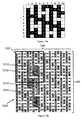
- Figure 6 is a weave diagram showing a unit cell or pattern square of a second fabric design to be woven in accordance with the teaching of the present invention; the weave diagram provides the weaving, or interlacing, pattern of the warp and weft yarns in one repeat of the fabric weave.
- the warp yarns are numbered from 1 to 10 across the top of the diagram, while the weft yarns are numbered from 1 to 10 along the left side.
- a black square indicates that a warp yarn is above (or passes over in the repeat) a weft yarn
- a white square indicates that the warp yarn is below a weft yarn at the selected location.
- the unit cell of Figure 6 represents one repeat of the weave pattern which is duplicated across the width and the length of the entire fabric; the weave pattern requires 10 sheds in the loom to control the position of the warp yarns, and the pattern repeats over 10 weft, such that an eleventh (11 th ) weft yarn will follow the same interlacing pattern as that shown for weft number 1 at the top of the diagram.
- warp yarn 1 passes over weft yarn 1, then passes under weft yarns 2, 3, 4 and 5, over weft yarn 6, and then under weft yarns 7 through 10; at this point, the path of warp yarn 1 repeats the illustrated pattern beginning from weft yarn 1.
- the adjacent warp yarn 2 also passes over weft yarn 1, as well as weft yarns 2 and 3, then under weft yarn 4, and then over weft yarns 5 through 10 to complete the pattern.
- Warp yarns 3, 5, 7 and 9 follow similar paths to that of warp 1, but are offset each to the other by one weft yarn (i.e.
- Warp yarns 4, 6, 8 and 10 follow similar paths to that of warp yarn 2, but are also offset, as if shifted "down", by three weft yarns. It is worth noting that the weave pattern shown in Figure 6 provides a long warp float which spans nine weft yarns in total; this is most apparent by examining the path of warp 10, which forms a continuous unbroken 9 weft float over weft yarns 1 through 9 in the pattern. Unlike fabrics produced according to the weave pattern shown in Figure 1 , the fabric produced using the weave pattern shown in Figure 6 , is not symmetrical, so that the two opposing planar surfaces of the resulting cloth are not identical.
- Figure 7 is a photograph of the PS (paper side) surface of a fabric 70 woven according to the weave pattern shown in Figure 6 ; this is the fabric surface which would, when in use, be used to form or convey the paper product that is to be produced using a fabric of the present invention.
- the weft yarns 100 are shown as oriented from left to right across the page, while the warp yarns 200 are oriented vertically down the page.
- the fabric shown in Figure 7 has been surfaced (mechanically abraded) so as to increase its surface contact area; note that the result of this surfacing appears as ovals in the warp yarn knuckles such as at 250.
- the weft yarn knuckles such as at 150 have also been surfaced to a lesser extent and appear colored in the photograph to enhance their appearance. This effect is opposite to what occurred in the fabric pattern of Figure 1 as shown by inspection of Figure 2 where it is apparent that the weft yarns stood proud of the fabric surface and were subjected to the majority of the surfacing process.
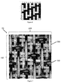
- Figure 8 presents a photograph of a unit cell 700 superimposed on the fabric sample 70 of Figure 7 which fabric has been woven according to the pattern presented in Figure 6 and provides one full repeat of the weave pattern.
- Figure 8 also shows in outline the fabric pockets provided by the weave pattern in the unit cell. Inspection of Figure 8 shows that there are 10 pockets in the unit cell 700, which is a single repeat of the weave pattern; the pockets are of two differing sizes and each is outlined on the PS fabric surface.
- the first pockets, such as at 810 are "larger" pockets, meaning they have a larger open surface area than the second pockets, such as at 820 (indicated with the numeral 2 in the Figure), which are smaller in relation to the first pockets.
- the larger first pockets are bordered with a dashed line, while smaller second pockets are bordered using a solid line.
- pocket 810 Inspection of a larger pocket such as 810 shows that it is bordered on two MD sides by two warp yarn knuckles 210 and 220, and on the other two CD sides by two weft yarn knuckles 110 and 120.
- the warp yarn knuckles 210 and 220 each "float", or pass over, five weft yarns on the longitudinal edges of larger pocket 810.
- pocket 810 is bounded at its upper end by weft yarn knuckle 110, and at the lower end by weft yarn knuckle 120; weft yarn knuckle 120 forms the "end" of warp yarn knuckle 210 while weft yarn knuckle 110 terminates warp yarn knuckle 220.
- warp yarn knuckle 210 Inspection of warp yarn knuckle 210 in Figure 8 shows that it floats over 9 consecutive weft yarns beginning at knuckle 120 and extending up the page where it also forms one boundary of the next (smaller) pocket 840. It can also be seen that weft yarn knuckle 110 forms a border of four pockets, including: large pocket 810, small pocket 820, as well as large pocket 830 and small pocket 840. Weft yarn knuckle 110 forms the top boundary of both pockets 810 and 820 where it floats over three warp in succession.
- small pocket 820 is bounded on top by weft yarn knuckle 110, which also forms part of the perimeter of large pocket 810; weft yarn knuckle 130 forms the bottom boundary of small pocket 820; warp floats 220 and 230 form the left and right sides respectively of small pocket 820. Warp float 220 also forms the left boundary of large pocket 810; the pattern continues in the manner just described throughout the fabric.
- Figure 8 thus shows a fabric woven according to the 10-shed pattern of Figure 6 which provides for 10 pockets of two differing sizes in each unit cell of the fabric.
- Each pocket is bounded by warp yarn knuckles or floats which pass over 9 consecutive weft yarns to form lateral MD sides of both the large pockets such as 810 and small pockets such as 820.
- Each pocket is also bounded on two sides by weft yarn knuckles or floats of two weft yarns each of which forms a float as they pass over three weft yarns.
- Comparison of Figure 8 with the weave pattern of Figure 6 clearly shows this float pattern.
- each of the first and second pockets is bounded by two warp yarn knuckles and two weft yarn knuckles which are arranged such that:
- Figures 9a , 10a , 11a , 12a and 13a are each weave diagrams of a unit cell or pattern square of third, fourth, fifth, sixth and seventh embodiments of fabrics which may be woven in accordance with the teaching of the present invention.
- the warp yarns in Figures 9a , 10a , 11a , 12a and 13a are numbered from 1 to 10 across the top of the diagram, while the weft yarns are numbered from 1 to 10 along the left side.
- a black square indicates that a warp yarn is above (or passes over in the repeat) a weft yarn, while a white square indicates that the warp yarn is below a weft yarn at the selected location.
- the unit cells of Figures 9a , 10a , 11a , 12a and 13a each represent one repeat of the indicated weave pattern which is duplicated across the width and the length of the entire fabric; the weave patterns of each diagram all require 10 sheds in the loom to control the position of the warp yarns, and the patterns repeat over 10 weft, such that an eleventh (11 th ) weft yarn will follow the same interlacing pattern as that shown for weft number 1 at the top of the diagrams.
- warp yarn 1 passes over weft yarn 1, then passes under weft yarns 2 through 10; at this point, the path of warp yarn 1 repeats the illustrated pattern beginning from weft yarn 1.
- the adjacent warp yarn 2 also passes over weft yarn 1, as well as weft yarns 2 and 3, then under weft yarn 4, and then over weft yarns 5 through 10 to complete the pattern.
- Warp yarns 3, 5, 7 and 9 follow similar paths to that of warp 1, but are offset each to the other by three weft yarns.
- Warp yarns 4, 6, 8 and 10 follow similar paths to that of warp yarn 2, but are also offset, as if shifted "down", by three weft yarns.
- the weave pattern shown in Figure 9a provides a long warp float which, like that presented in Figure 6 , has a float length of nine weft yarns; this is most readily apparent by examining the path of warp yarn10 at the far right of the Figure 9a weave diagram, which can be seen to pass over weft yarns 1 through 9.
- the fabric produced using the weave pattern shown in Figure 9a is symmetrical, so that the two opposing planar surfaces of the resulting cloth are identical, similar to Figure 1 as previously discussed.
- Figure 9b is a planar view of a representation of a fabric 900 woven according to the weave pattern of Figure 9a ; a single repeat of the pattern square 901 is indicated at the upper left corner of the representation.
- the pattern square 901 corresponds to the weave diagram of Figure 9a; Figure 9b shows the appearance of four repeats of the Figure 9a weave pattern.
- the warp yarns 200 are oriented vertically in the representation, while the weft yarns 100 are arranged horizontally across the representation.
- Four exemplary pockets 910, 912, 914 and 916 are identified in the pattern square 901; pockets 910 and 916 are both large pockets, meaning they have a larger open surface area than the small pockets, such as 912 and 914, which are smaller in relation to the large pockets. Inspection of the pattern square 901 shows there are 5 small pockets such as 912 and 914, and 5 large pockets such as 910 and 916 within the pattern square 901.
- a large pocket such as 910 shows that it is bordered on each side by two warp yarn knuckles and, at the top and bottom, by two weft yarn knuckles each of which float over three consecutive warp yarns in the pattern as previously discussed in relation to Figures 1 and 6 .
- Each large pocket such as 910 is bordered on the left and right by a warp yarn knuckle that floats over 5 weft yarns.
- Each small pocket such as 914 is bordered by a warp yarn knuckle which floats over three weft yarns.
- the warp and weft yarn knuckles of the large and small pockets each share a common boundary with adjacent small and large pockets, as is apparent from the representation of Figure 9b .
- An isometric representation of the fabric 900 presented in planar view in Figure 9b is provided in Figure 9c .
- the weft yarns are collectively identified as 100 while the warp yarns are collectively identified as 200.
- the fabric 900 has a semi-duplex construction similar to that exhibited in the fabric of Figure 5 so that alternate warp yarns form floats on each of the first and second surfaces of the fabric.
- Figure 10a presents a weave diagram of a fabric according to a fourth embodiment of the present invention.
- warp yarn 1 passes over weft yarns 1 and 2, then passes under weft yarns 3 through 10; at this point, the path of warp yarn 1 repeats the illustrated pattern beginning from weft yarn 1.
- the adjacent warp yarn 2 passes over weft yarns 1, 2 and 3, then under weft yarn 4, and then over weft yarns 5 through 10 to complete the pattern.
- Warp yarns 3, 5, 7 and 9 follow similar paths to that of warp 1, but are offset each to the other by two weft yarns.
- Warp yarns 4, 6, 8 and 10 follow similar paths to that of warp yarn 2, but are also offset, as if shifted "down", by three weft yarns.
- the weave pattern shown in Figure 10a thus provides a long warp float which nine spans consecutive weft yarns in total; this is most apparent by examining the path of warp 10 in Figure 10a , which forms a 9 weft float over weft yarns 1 through 9.
- the fabric produced using the weave pattern shown in Figure 10a is not symmetrical, so that the two opposing planar surfaces of the resulting cloth are not identical, similar to Figure 6 as previously discussed.
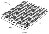
- Figure 10b is a planar view of a representation of a fabric 1000 represented as if woven according to the weave pattern shown in Figure 10a ; a single repeat of the pattern square provided in Figure 10a is indicated as 1001 at the upper left corner of the representation.
- Four repeats of the weave pattern of Figure 10a are shown in the representation of Figure 10b .
- the warp yarns 200 are oriented vertically in the representation, while the weft yarns 100 are arranged horizontally across the representation.
- Four exemplary pockets 1010, 1012, 1014 and 1016 are identified in the pattern square 1001; pockets 1010 and 1016 are both large pockets, meaning they have a larger open surface area than the small pockets, such as 1012 and 1014, which are smaller in relation to the large pockets. Inspection of the pattern square 1001 shows there are 5 small pockets such as 1012 and 1014, and 5 large pockets such as 1010 and 1016.
- a large pocket such as 1010 shows that it is bordered by two warp yarn knuckles and two weft yarn knuckles.
- the weft yarns 100 each float over three consecutive warp yarns as they form the upper and lower boundaries of both the large and small pockets in the manner previously discussed in relation to Figures 1 and 6 .
- Each large pocket such as 1010 is bordered on the left and right by a warp yarn knuckle that floats over 5 weft yarns.
- Each small pocket such as 1014 is bordered by a warp yarn knuckle which floats over three weft yarns.
- FIG. 10c An isometric representation of the fabric 1000 shown in Figure 10b is provided in Figure 10c .
- Figure 10c As in Figures 9b and 9c , the weft yarns are collectively identified as 100 while the warp yarns are collectively identified as 200.
- the representation of Figure 10c shows that the fabric has a semi-duplex construction similar to that of the earlier first, second and third embodiments of the invention.
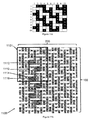
- Figure 11a is a weave diagram of a fifth embodiment of a 10-shed semi-duplex fabric of the present invention.
- warp yarn 1 passes under weft yarns 1, 2 and 3, then passes over weft yarn 4, under weft 5, 6, 7 and 8, over weft yarn 9 and under weft 10, at which the point the pattern repeats from weft yarn 1.
- This interweaving pattern is repeated for warps 3, 5, 7 and 9 but each is offset in the pattern to the other by two weft yarns.
- Adjacent warp yarn 2 passes over weft yarn 1, under 2, then over wefts 3 through 6, under weft 7, and over weft 8,9 and 10 at which point the interweaving arrangement of this yarn repeats.
- Warp yarns 4, 6, 8 and 10 follow similar paths to that of warp yarn 2, but are also offset, as if shifted "down", by two weft yarns.
- the weave pattern shown in Figure 11a thus provides for two warp yarn floats in the repeat, each of which floats over 4 weft yarns; this is most apparent by examining the path of warp 10, which forms a 4 weft float over weft yarns 1 through 4 and 6 through 9.
- the fabric produced using the weave pattern shown in Figure 11a is symmetrical, so that the two opposing planar surfaces of the resulting cloth are identical, similar to that of Figure 1 as previously discussed.
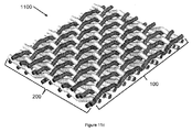
- Figure 11b is a planar view of a representation of a fabric 1100 represented as if woven according to the weave pattern shown in Figure 11a ; a single repeat of the pattern square provided in Figure 11a is indicated as 1101 at the upper left corner of the representation of Figure 11b .
- Four repeats of the weave pattern of Figure 11a are shown in the representation of Figure 11b .
- the warp yarns 200 are oriented vertically in the representation, while the weft yarns 100 are arranged horizontally across the representation.
- pockets 1110, 1112, 1114 and 1116 are identified in the pattern square 1101; pockets 1110 and 1116 are both large pockets, meaning they have a larger open surface area than the small pockets, such as 1112 and 1114, which are smaller in relation to the large pockets. Inspection of the pattern square 1001 shows there are 10 small pockets such as 1112 and 1114, and 10 large pockets such as 1110 and 1116.
- a large pocket such as 1110 shows that it is bordered by two warp yarn knuckles and two weft yarn knuckles.
- the weft yarns 100 forming the upper and lower boundaries of both the large and small pockets each float over three consecutive warp yarns in the pattern, in the manner previously discussed.
- Each large pocket such as 1110 is bordered on the left and right by a warp yarn knuckle that floats over 2 weft yarns before reaching a weft knuckle.
- Each small pocket such as 1112 is bordered by a warp yarn knuckle which floats over one weft yarn.
- each of pockets 1110 and 1112 share a warp float that extends over 4 weft yarns.
- the upper boundary of small pocket 1112 is formed by a float of weft yarn 4 as it passes over warps 3, 4 and 5 (see Figure 11a ).
- the lower boundary is formed by a float of weft yarn 6 as it passes over warps 5, 6 and 7; weft yarn 6 also forms the upper boundary of large pocket 1110, which is bordered on the left by a float of warp yarn 4, which floats terminates at the bottom of the pocket when it passes beneath a float of weft yarn 9 as shown in Figure 11a .
- FIG. 11b An isometric representation of the fabric 1100 shown in Figure 11b is provided in Figure 11c .
- Figure 11c as in the previous Figures such as 9b and 9c, the weft yarns are collectively identified as 100 while the warp yarns are collectively identified as 200.
- the representation of Figure 11c shows that the fabric has a semi-duplex construction similar to that of the earlier embodiments of the invention as have been previously described.
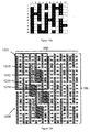
- Figure 12a is a weave diagram of a fabric according to a sixth embodiment of the invention. Examination of the weave diagram of Figure 12a shows that, beginning at the upper left corner, warp yarn 1 passes under weft yarn 1, then passes over the remaining weft 2 through 10 in the pattern to form a float over those 9 yarns; at this point, the path of warp yarn 1 repeats the illustrated pattern beginning from weft yarn 1. Warp yarn 2 passes under weft yarns 1 through 3, over weft 4, and then under remaining weft 5 through 10 to complete the pattern. Warp yarns 3, 5, 7 and 9 follow similar paths to that of warp 1, but are offset each to the other by three weft yarns.
- Warp yarns 4, 6, 8 and 10 follow similar paths to that of warp yarn 2, but are also offset, as if shifted "up" by three weft yarns.
- the weave pattern shown in Figure 11a thus provides a long warp float which, like that presented in Figure 6 , has a float length of nine weft yarns; this is most readily apparent by examining the path of warp yarn 1 at the far left of the Figure 12a weave diagram which, as shown, passes over weft yarns 2 through 10.
- the fabric produced using the weave pattern shown in Figure 12a is symmetrical, so that the two opposing planar surfaces of the resulting cloth are identical, similar to Figure 1 as previously discussed.
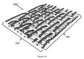
- Figure 12b is a planar view of a representation of a fabric 1200 woven according to the weave pattern of Figure 12a ; a single repeat of the pattern square 1201 is indicated at the upper left corner of the representation 1200.
- the pattern square 1201 corresponds to the weave diagram of Figure 12a and shows the appearance of the yarns as if interwoven according to the pattern of Figure 12a.
- Figure 12b shows the appearance of four repeats of the Figure 12a weave pattern.
- the warp yarns 200 are oriented vertically in the representation, while the weft yarns 100 are arranged horizontally across the representation.
- pockets 1210, 1212, 1214 and 1216 are identified in the pattern square 1201; pockets 1210 and 1216 are both large pockets, meaning they have a larger open surface area than the small pockets, such as 1212 and 1214, which are smaller in relation to the large pockets. Inspection of the pattern square 1201 shows there are 5 small pockets such as 1212 and 1214, and 5 large pockets such as 1210 and 1216.
- a large pocket such as 1210 shows that it is bordered by two warp yarn knuckles and two weft yarn knuckles.
- the weft yarns 100 forming the upper and lower boundaries of pocket 1210 each float over three consecutive warp yarns in the pattern, forming the upper and lower boundaries of both the large and small pockets such as 1212, 1214 and 1216 in the manner previously discussed in relation to Figures 1 and 6 .
- Each large pocket such as 1210 is bordered on the left and right by a warp yarn knuckle that floats over 5 weft yarns.
- Each small pocket such as 1214 is bordered by a warp yarn knuckle which floats over three weft yarns.
- the warp and weft yarn knuckles of the large and small pockets each share a common boundary with adjacent small and large pockets, as is apparent from the representation of Figure 12b .
- An isometric representation of the fabric 1200 is provided in Figure 12c .
- the weft yarns are collectively identified as 100 while the warp yarns are collectively identified as 200.
- the fabric 1200 has a semi-duplex construction similar to that exhibited in the fabric of Figure 5 .
- Figure 13a is a weave diagram of a fabric according to a seventh embodiment of the invention. Examination of the weave diagram of Figure 12a shows that, beginning at the upper left corner, warp yarn 1 passes under weft yarn 1, then passes over the remaining weft 2 through 10 in the pattern to form a float over those 9 yarns; at this point, the path of warp yarn 1 repeats the illustrated pattern beginning from weft yarn 1. Warp yarn 2 passes under weft yarns 1 through 3, over weft 4, under weft yarns 5, 6, 7 and 8, over weft 9, and then under weft yarn 10 to complete the pattern. Warp yarns 3, 5, 7 and 9 follow similar paths to that of warp 1, but are offset each to the other by three weft yarns.
- Warp yarns 4, 6, 8 and 10 follow similar paths to that of warp yarn 2, but are also offset, as if shifted "down" by one weft yarn.
- the weave pattern shown in Figure 13a thus provides a long warp float which, like that presented in Figures 6 , 9a and 12a has a float length of nine weft yarns; this is most readily apparent by examining the path of warp yarn 1 at the far left of the Figure 13a weave diagram in which warp 1 passes over weft yarns 2 through 10 to provide a float length of 9 yarns.
- the fabric produced using the weave pattern shown in Figure 13a is not symmetrical, so that the two opposing planar surfaces of the resulting cloth are not identical, similar to Figure 6 as previously discussed.
- Figure 13b is a planar view of a representation of a fabric 1300 woven according to the weave pattern of Figure 13a ; a single repeat of the pattern square 1301 is indicated at the upper left corner of the representation 1300.
- the pattern square 1301 corresponds to the weave diagram of Figure 13a and shows the appearance of the yarns as if interwoven according to the pattern of Figure 13a.
- Figure 13b shows the appearance of four repeats of the Figure 13a weave pattern.
- the warp yarns 200 are oriented vertically in the representation, while the weft yarns 100 are arranged horizontally across the representation.
- pockets 1310, 1312, 1314 and 1316 are identified in the pattern square 1301; pockets 1310 and 1316 are both large pockets, meaning they have a larger open surface area than the small pockets, such as 1312 and 1314, which are smaller in relation to the large pockets. Inspection of the pattern square 1301 shows there are 5 small pockets such as 1312 and 1314, and 5 large pockets such as 1310 and 1316. Each small pocket includes 3 weft yarns and one warp yarn forming the pocket bottom. While each large pocket includes 5 weft yarns and 1 warp yarn in the pocket bottom.
- a large pocket such as 1310 shows that it is bordered on each side by two warp yarn knuckles and across the top and bottom by two weft yarn knuckles.
- the weft yarns 100 each float over three consecutive warp yarns in the pattern, forming the upper and lower boundaries of both the large and small pockets in the manner previously discussed in relation to Figures 1 and 6 .
- Each large pocket such as 1310 is bordered on the left and right by a warp yarn knuckle that floats over 5 consecutive weft yarns.
- Each small pocket such as 1312 is bordered by a warp yarn knuckle which floats over three consecutive weft yarns.
- the warp and weft yarn knuckles of the large and small pockets each share a common boundary with adjacent small and large pockets, as is apparent from the representation of Figure 13b .
- An isometric representation of the fabric 1300 is provided in Figure 13c .
- the weft yarns are again collectively identified as 100 while the warp yarns are collectively identified as 200.
- the fabric 1300 has a semi-duplex construction similar to that exhibited in the fabric of Figure 5 .
- the fabrics of the present invention are typically woven using either circular or generally rectangular cross-sectional shaped warp and weft yarns.
- Round cross-sectional yarns are preferred for use as both the warp and weft yarns, however, either can be used in any desired combination depending upon the intended end use of the fabric and facilities and equipment available to the fabric manufacturer.
- circular cross-section warp yarns having a diameter of about 0.35mm can be used, however the selected warp yarn diameter may range from as low as about 0.22mm to as high as about 0.45mm, with the fabric mesh in the range of about 44 to 46 warp yarns per inch (17.3 to 18.1 warp yarns/cm).
- the weft yarns will generally also be of circular cross-sectional shape, with diameter ranging from about 0.3mm to about 0.8mm, woven at a knocking of from about 30 to 60 weft/in. (11.8 to 23.6 weft yarns/cm).
- the woven fabric may be subjected to a surfacing process to increase its PS surface contact area to a desired level following weaving; surface areas of about 15% to 20% are typical, however, the fabric may be surfaced to provide a contact area of as much as 30% depending on need.
- this surfacing step may be eliminated depending on the contact area achieved and end use requirements, or at least significantly reduced.
- the resulting fabrics will desirably have an air permeability that is at least 600 cfm (cubic feet per minute) and is preferably higher.
- the fabrics of the invention preferably exhibit pockets of two differing sizes in the PS surface which pockets are generally MD oriented.
- MD oriented pockets tend to provide a tissue or towel product which may exhibit improved tactile properties, such as softness, in comparison to similar products formed using a fabric in which the pockets are predominantly CD oriented.
- the fabrics of the invention may be treated with a contaminant resistant coating so as to improve their ability to run "clean” and to shed undesirable particulate matter and chemical deposits such as may be present in the papermaking environment.
Landscapes
- Engineering & Computer Science (AREA)
- Textile Engineering (AREA)
- Woven Fabrics (AREA)
- Paper (AREA)
Claims (21)
- Etoffe tissée monocouche de séchoir à air traversant (TAD) (10, 70, 900, 1000, 1100, 1200, 1300), laquelle étoffe est tissée selon un motif répété de manière à former une étoffe (10, 70, 900, 1000, 1100, 1200, 1300) ayant une première et seconde surface généralement planaires, une direction de machine et une direction transversale de machine lesquelles directions sont mutuellement perpendiculaires et coplanaires avec la première et la seconde surface, dans lequel dans le motif répété, des fils de chaîne (200) et des fils de trame (100) sont entrelacés pour fournir une pluralité de croisements de fils de trame et de chaîne (250, 150) formant la première surface d'étoffe généralement planaire et des poches (310, 330, 350, 370, 810, 830, 910, 916, 1010, 1016, 1110, 1116, , 1210, 1216, 1310, 1316 ; 320, 340, 360, 820, 840, 912, 914, 1012, 1014, 1112, 1114, 1212, 1214, 1312, 1314)définies entre deux paires adjacentes de croisements de fils de chaîne et de trame (250, 150), les poches (310, 330, 350, 370, 810, 830, 910, 916, 1010, 1016, 1110, 1116, 1210, 1216, 1310, 1316 ; 320, 340, 360, 820, 840, 912, 914, 1012, 1014, 1112, 1114, 1212, 1214, 1312, 1314) ayant une zone qui est définie par les paires de croisements de fils de chaîne et de fils de trame (250, 150) et une profondeur qui est évidée au-dessous de la première surface planaire, dans lequel dans chaque répétition du motif :a) les poches (310, 330, 350, 370, 810, 830, 910, 916, 1010, 1016, 1110, 1116, 1210, 1216, 1310, 1316 ; 320, 340, 360, 820, 840, 912, 914, 1012, 1014, 1112, 1114, 1212, 1214, 1312, 1314) sont constituées de premières poches (310, 330, 350, 370 ; 810 ; 910, 916 ; 1010, 1016 ; 1110, 1116 ; 1210, 1216 ; 1310, 1316) ayant une première zone ouverte exposée sur la première surface d'étoffe et des secondes poches (320, 340, 360 ; 820 ; 912, 914 ; 1012, 1014 ; 1112, 1114 ; 1212, 1214 ; 1312, 1314) ayant une seconde zone ouverte exposée sur la première surface d'étoffe ;b) un périmètre de chacune de la première et seconde poche (310, 330, 350, 370, 810, 830, 910, 916, 1010, 1016, 1110, 1116, 1210, 1216, 1310, 1316 ; 320, 340, 360, 820, 840, 912, 914, 1012, 1014, 1112, 1114, 1212, 1214, 1312, 1314) est défini par deux des croisements de fils de chaîne (210, 220, 230, 240, 250) et deux des croisements de fils de trame (110, 120, 130, 150) ;c) un nombre de premières poches (310, 330, 350, 370 ; 810 ; 910, 916, 1010, 1016 ; 1110, 1116 ; 1210, 1216 ; 1310, 1316) dans le motif répété est égal à un nombre des secondes poches (320, 340, 360 ; 820 ; 912, 914 ; 1012, 1014 ; 1112, 1114 ; 1212, 1214 ; 1312, 1314) ;d) la zone ouverte définie par le périmètre des premières poches (310, 330, 350, 370 ; 810 ; 910, 916, 1010, 1016 ; 1110, 1116 ; 1210, 1216 ; 1310, 1316) est différente de la zone ouverte définie par le périmètre des secondes poches (320, 340, 360 ; 820 ; 912, 914 ; 1012, 1014 ; 1112, 1114 ; 1212, 1214 ; 1312, 1314) ;e) les premières poches (310, 330, 350, 370 ; 810 ; 910, 916 ; 1010, 1016 ; 1110, 1116 ; 1210, 1216 ; 1310, 1316) et les secondes poches (320, 340, 360 ; 820 ; 912, 914 ; 1012, 1014 ; 1112, 1114 ; 1212, 1214 ; 1312, 1314) sont agencées dans un motif sergé en diagonale sur la première surface d'étoffe ;caractérisé en ce quef) la surface de fond de chacune des poches est définie par un des fils de chaîne (200) et au moins un des fils de trame (100) et est évidée au-dessous de la première surface d'étoffe généralement planaire ;g) chacun des croisements de fils de chaîne (210, 220, 230, 240, 250) est séparé d'un croisement adjacent des croisements de fils de chaîne (210, 220, 230, 240, 250) par un des fils de chaîne (200) ;h) les deux croisements de fils de chaîne (210, 220, 230, 240, 250) et les deux croisements des fils de trame (110, 120, 130, 150) définissant les périmètres de chacune de la première et la seconde poche (310, 330, 350, 370, 810, 830, 910, 916, 1010, 1110, 1116, 1210, 1216, 1310, 1316 ; 320, 340, 360, 820, 840, 912, 914, 1012, 1014, 1112, 1114, 1212, 1214, 1312, 1314) sont agencés de telle sorte que :i. Les croisements de fils de chaîne (210, 220, 230, 240, 250) flottent sur 4 à 9 des fils de trame (100) ;ii. Les croisements de fils de trame (110, 120, 130, 150) flottent sur 3 des fils de chaîne (200) ;iii. Chacun des croisements de fils de chaîne (210, 220, 230, 240, 250) définit des côtés de direction de machine (MD) de deux des premières poches (310, 330, 350, 370 ; 810 ; 910, 916, 1010, 1016 ; 1110, 1116 ; 1210, 1216 ; 1310, 1316) et deux des secondes poches (320, 340, 360 ; 820 ; 912, 914 ; 1012, 1014 ; 1112, 1114 ; 1212, 1214 ; 1312, 1314) ; etiv. Chacun des croisements de fils de trame (110, 120, 130, 150) définit des côtés de direction transversale de machine (CD) de deux des premières poches (310, 330, 350, 370 ; 810 ; 910, 916 ; 1010, 1016 ; 1110, 1116 ; 1210, 1216 ; 1310, 1316) et deux des secondes poches (320, 340, 360 ; 820, 912, 914 ; 1012, 1014 ; 1112, 1114 ; 1212, 1214 ; 1312, 1314).
- Etoffe (10, 70, 900, 1000, 1100, 1200, 1300) selon la revendication 1, dans laquelle le motif répété est un motif à 10 encroix nécessitant 10 fils de chaîne (200) et 10 fils de trame (100) dans chaque répétition, et le motif répété fournit N poches de deux des premières poches et deux des secondes poches (310, 330, 350, 370, 810, 830, 910, 916, 1010, 1016, 1110, 1116, 1210, 1216, 1310, 1316 ; 320, 340, 360, 820, 840, 912, 914, 1012, 1014, 1112, 1114, 1212, 1214, 1312, 1314) sur au moins la première surface d'étoffe généralement planaire, et N est un entier ≥ 10.
- Étoffe (10, 70, 900, 1000, 1100, 1200, 1300) selon la revendication 1, dans laquelle à l'intérieur d'une répétition du motif répété dans l'étoffe, des fils alternés des fils de chaîne (100) forment les croisements qui définissent les périmètres de la première et seconde poches de deux des premières poches et deux des secondes poches (310, 330, 350, 370, 810, 830, 910, 916, 1010, 1016, 1110, 1116, 1210, 1216, 1310, 1316 ; 320, 340, 360, 820, 840, 912, 914, 1012, 1014, 1112, 1114, 1212, 1214, 1312, 1314) sur seulement une des deux surfaces généralement planaires.
- Étoffe (10, 70, 900, 1000, 1100, 1200, 1300) selon la revendication 3, dans laquelle les fils de chaîne alternés (100) fournissent les croisements qui définissent les périmètres de la première et seconde poches de deux des premières poches et deux des secondes poches (310, 330, 350, 370, 810, 830, 910, 916, 1010, 1016, 1110, 1116, 1210, 1216, 1310, 1316 ; 320, 340, 360, 820, 840, 912, 914, 1012, 1014, 1112, 1114, 1212, 1214, 1312, 1314) sur la première surface généralement planaire de l'étoffe.
- Étoffe (10, 70, 900, 1000, 1100, 1200, 1300) selon la revendication 1, dans laquelle les croisements de fils de chaîne (210, 220, 230, 240, 250) qui définissent les périmètres de la première et la seconde poche (310, 330, 350, 370, 810, 830, 910, 916, 1010, 1016, 1110, 1116, 1210, 1216, 1310, 1316 ; 320, 340, 360, 820, 840, 912, 914, 1012, 1014, 1112, 1114, , 1212, 1214, 1312, 1314) flottent sur au moins 4 des fils de trame (100) de la première surface généralement planaire de l'étoffe.
- Etoffe (70, 900, 1000, 1100, 1200, 1300) selon la revendication 2, dans laquelle lescroisements de fils de chaîne (210, 220, 230, 240, 250) dans une répétition unique flottent sur 9 fils de trame (100).
- Étoffe (10, 70, 900, 1000, 1100, 1200, 1300) selon la revendication 1, dans laquelle chacun des croisements de fils de chaîne (210, 220, 230, 240, 250) forme les côtés MD de quatre des poches (310, 330, 350, 370, 810, 830, 910, 916, 1010, 1016, 1110, 1116, , 1210, 1216, 1310, 1316 ;320, 340, 360, 820, 840, 912, 914, 1012, 1014, 1112, 1114, 1212, 1214, 1312, 1314).
- Étoffe (10, 70, 900, 1000, 1100, 1200, 1300) selon la revendication 1, dans laquelle les croisements de fils de trame (150) qui définissent les périmètres de la première et seconde poche (310, 330, 350, 370, 810, 830, 910, 916, 1010, 1016, 1110, 1116, 1210, 1216, 1310, 1316 ; 320, 340, 360, 820, 840, 912, 914, 1012, 1014, 1112, 1114, 1212, 1214, 1312, 1314) flottent sur trois des fils de chaîne (200).
- Étoffe (10, 70, 900, 1000, 1100, 1200, 1300) selon la revendication 1, dans laquelle chacune des poches (310, 330, 350, 370, 810, 830, 910, 916, 1010, 1016, 1110, 1116, , 1210, 1216, 1310, 1316 ; 320, 340, 360, 820, 840, 912, 914, 1012, 1014, 1112, 1114, 1212, 1214, 1312, 1314) est séparée dans la CD d'une poche adjacente des poches (310, 330, 350, 370, 810, 830, 910, 916, 1010, 1016, 1110, 1116, 1210, 1216, 1310, 1316 ; 320, 340, 360, 820, 840, 912, 914, 1012, 1014, 1112, 1114, 1212, 1214, 1312, 1314) par un des fils de chaîne (200).
- Étoffe (10, 70, 900, 1000, 1100, 1200, 1300) selon la revendication 1, dans laquelle chacune des poches (310, 330, 350, 370, 810, 830, 910, 916, 1010, 1016, 1110, 1116, 1210, 1216, 1310, 1316 ; 320, 340, 360, 820, 840, 912, 914, 1012, 1014, 1112, 1114, 1212, 1214, 1312, 1314)est séparée dans la MD de la poche adjacente (310, 330, 350, 370, 810, 830, 910, 916, 1010, 1016, 1110, 1116, 1210, 1216, 1310, 1316 ; 320, 340, 360, 820, 840, 912, 914, 1012, 1014, 1112, 1114, 1212, 1214, 1312, 1314) par un des fils de trame (100).
- Étoffe (10, 70, 900, 1000, 1100, 1200, 1300) selon la revendication 1, dans laquelle chacune des poches (310, 330, 350, 370, 810, 830, 910, 916, 1010, 1016, 1110, 1116, 1210, 1216, 1310, 1316 ; 320, 340, 360, 820, 840, 912, 914, 1012, 1014, 1112, 1114, 1212, 1214, 1312, 1314) est séparée d'une poche adjacente des poches (310, 330, 350, 370, 810, 830, 910, 916, 1010, 1016, 1110, 1116, 1210, 1216, 1310, 1316 ; 320, 340, 360, 820, 840, 912, 914, 1012, 1014, 1112, 1114, 1212, 1214, 1312, 1314) par un des croisements de fils de chaîne (210, 220, 230, 240, 250) et un des croisements de fils de trame (110. 120, 130, 150).
- Étoffe (10, 70, 900, 1000, 1100, 1200, 1300) selon la revendication 1, dans laquelle chacun des croisements de fils de chaîne (210, 220, 230, 240, 250) est séparé dans la CD d'un croisement adjacent des croisements de fils de chaîne (210, 220, 230, 240, 250) sur la même surface d'étoffe par un des fils de chaîne (200).
- Étoffe (10, 1100) selon la revendication 2, dans laquelle 50 % des fils de chaîne (200) flottent sur 8 des fils de trame (100) dans une répétition du motif tissé de manière à former deux des croisements de fils de chaîne (210, 220, 230, 240, 250) sur une des deux surfaces d'étoffe, dans laquelle chacun desdits croisements de fils de chaîne (210, 220, 230, 240, 250) flotte sur 4 des fils de trame (100).
- Étoffe (10, 70, 900, 1000, 1100, 1200, 1300) selon la revendication 1, dans laquelle 50 % des fils de chaîne (200) dans une répétition du motif tissé forment les croisements de fils de chaîne (210, 220, 230, 240, 250) sur une surface de l'étoffe.
- Étoffe (10, 70, 900, 1000, 1100, 1200, 1300) selon la revendication 1, dans laquelle une zone de contact de surface de l'étoffe est d'au moins 14%.
- Etoffe (10, 70, 900, 1000, 1100, 1200, 1300) selon la revendication 1, dans laquelle l'étoffe est
un étoffe monocouche pour la fabrication du papier, la première et la seconde surface généralement planaire correspondent à une surface de support de papier et une surface côté machine, les poches (310, 330, 350, 370, 810, 830, 910, 916, 1010, 1016, 1110, 1116, , 1210, 1216, 1310, 1316 ; 320, 340, 360, 820, 840, 912, 914, 1012, 1014, 1112, 1114, 1212, 1214, 1312, 1314) sont définies entre deux paires adjacentes de croisements de fils de chaîne et fils de trame (210, 220, 240, 250 ; 110, 120, 150) sur chacune de la première et la seconde surface généralement planaires, les poches (310, 330, 350, 370, 810, 830, 910, 916, 1010, 1110, 1116, 1210, 1216, 1310, 1316 ; 320, 340, 360, 820, 840, 912, 914, 1012, 1014, 1112, 1114, 1212, 1214, 1312, 1314) ayant une zone qui est définie par les paires des croisements de fils de chaîne et fils de trame (210, 220, 230, 240, 250 ; 110, 120, 150) et une profondeur qui est évidée au-dessous de la première surface planaire ;
les croisements de fils de chaîne (210, 220, 230, 240, 250) d'un premier groupe de fils de chaîne (200) constitué de fils alternés de fils de chaîne (200) forment les côtés des poches (310, 330, 350, 370, 810, 830, 910, 916, 1010, 1016, 1110, 1116, 1210, 1216, 1310, 1316 ; 320, 340, 360, 820, 840, 912, 914, 1012, 1014, 1112, 1114, 1212, 1214, 1312, 1314) sur la surface de support du papier de l'étoffe et forment les fonds des poches (310, 330, 350, 370, 810, 830, 910, 916, 1010, 1016, 1110, 1116, , 1210, 1216, 1310, 1316 ; 320, 340, 360, 820, 840, 912, 914, 1012, 1014, 1112, 1114, 1212, 1214, 1312, 1314) sur une surface côté machine de l'étoffe ; et
les croisements de fils de chaîne (210, 220, 230, 240, 250) d'un second groupe de fils de chaîne (200) constituée des fils de chaîne restants (200) qui ne sont pas dans le premier groupe forment les côtés des poches sur la surface du côté machine et forment les fonds des poches (310, 330, 350, 370, 810, 830, 910, 916, 1010, 1016, 1110, 1116, 1210, 1216, 1310, 1316 ; 320, 340, 360, 820, 840, 912, 914, 1012, 1014, 1112, 1114, 1212, 1214, 1312, 1314) sur la surface de support du papier. - Étoffe (10, 70, 900, 1000, 1100, 1200, 1300) selon la revendication 16, dans laquelle les poches (310, 330, 350, 370, 810, 830, 910, 916, 1010, 1016, 1110, 1116, 1210, 1216, 1310, 1316 ; 320, 340, 360, 820, 840, 912, 914, 1012, 1014, 1112, 1114, 1212, 1214, 1312, 1314) sur chacune des surfaces d'étoffe sont de deux tailles différentes.
- Étoffe (10, 70, 900, 1000, 1100, 1200, 1300) selon la revendication 16, dans laquelle chacun des croisements de fils de chaîne (210, 220, 230, 240, 250) forme les côtés de 4 des poches (310, 330, 350, 370, 810, 830, 910, 916, 1010, 1016, 1110, 1116, 1210, 1216, 1310, 1316 ; 320, 340, 360, 820, 840, 912, 914, 1012, 1014, 1112, 1114, 1212, 1214, 1312, 1314).
- Étoffe (10, 70, 900, 1000, 1100, 1200, 1300) selon la revendication 16, dans laquelle chacun des fils de trame (110, 120, 130, 150) forme les côtés de 4 des poches (310, 330, 350, 370, 810, 830, 910, 916, 1010, 1016, 1110, 1116, 1210, 1216, 1310, 1316 ; 320, 340, 360, 820, 840, 912, 914, 1012, 1014, 1112, 1114, 1212, 1214, 1312, 1314).
- Étoffe (10, 70, 900, 1000, 1100, 1200, 1300) selon la revendication 16, dans laquelle les poches (310, 330, 350, 370, 810, 830, 910, 916, 1010, 1016, 1110, 1116, 1210, 1216, 1310, 1316 ; 320, 340, 360, 820, 840, 912, 914, 1012, 1014, 1112, 1114, 1212, 1214, 1312, 1314) sur chacune des surfaces de l'étoffe sont séparées par des poches adjacentes des poches (310, 330, 350, 370, 810, 830, 910, 916, 1010, 1016, 1110, 1116, 1210, 1216, 1310, 1316 ; 320, 340, 360, 820, 840, 912, 914, 1012, 1014, 1112, 1114, 1212, 1214, 1312, 1314) par un fil unique des fils (100, 200) dans chaque direction.
- Étoffe (10, 70, 900, 1000, 1100, 1200, 1300) selon la revendication 16, dans laquelle les coins opposés de chacune des poches (310, 330, 350, 370, 810, 830, 910, 916, 1010, 1016, 1110, 1116, 1210, 1216, 1310, 1316 ; 320, 340, 360, 820, 840, 912, 914, 1012, 1014, 1112, 1114, 1212, 1214, 1312, 1314) sont formés par les croisements de fils de chaîne (210, 220, 230, 240, 250) et d'autres coins opposés sont formés par les croisements de fils de trame (110, 120, 130, 150).
Applications Claiming Priority (2)
| Application Number | Priority Date | Filing Date | Title |
|---|---|---|---|
| US201161539646P | 2011-09-27 | 2011-09-27 | |
| PCT/US2012/057003 WO2013048992A1 (fr) | 2011-09-27 | 2012-09-25 | Tissu de séchage à traversée d'air semi-recto-verso à dix foules |
Publications (3)
| Publication Number | Publication Date |
|---|---|
| EP2761069A1 EP2761069A1 (fr) | 2014-08-06 |
| EP2761069A4 EP2761069A4 (fr) | 2015-04-29 |
| EP2761069B1 true EP2761069B1 (fr) | 2016-07-20 |
Family
ID=47996324
Family Applications (1)
| Application Number | Title | Priority Date | Filing Date |
|---|---|---|---|
| EP12835839.7A Active EP2761069B1 (fr) | 2011-09-27 | 2012-09-25 | Tissu de séchage à traversée d'air semi-recto-verso à dix foules |
Country Status (5)
| Country | Link |
|---|---|
| US (1) | US9422666B2 (fr) |
| EP (1) | EP2761069B1 (fr) |
| CN (1) | CN103827370B (fr) |
| MX (1) | MX347481B (fr) |
| WO (1) | WO2013048992A1 (fr) |
Families Citing this family (18)
| Publication number | Priority date | Publication date | Assignee | Title |
|---|---|---|---|---|
| US9771684B2 (en) * | 2013-12-17 | 2017-09-26 | Voith Patent Gmbh | Woven fabric belt for a fibrous-web machine |
| FR3023564B1 (fr) * | 2014-07-11 | 2017-03-24 | Perrin & Fils | Tissu et article d'habillement comprenant des zones de compression et methode d'obtention d'un tel tissu. |
| DE102014223972A1 (de) * | 2014-11-25 | 2016-05-25 | Voith Patent Gmbh | Doppelschlaufennaht in Bespannung |
| US10633792B2 (en) | 2015-02-11 | 2020-04-28 | Voith Patent Gmbh | Papermaking fabric |
| US10138601B2 (en) | 2015-06-08 | 2018-11-27 | Gpcp Ip Holdings Llc | Soft absorbent sheets, structuring fabrics for making soft absorbent sheets, and methods of making soft absorbent sheets |
| US9963831B2 (en) | 2015-06-08 | 2018-05-08 | Gpcp Ip Holdings Llc | Soft absorbent sheets, structuring fabrics for making soft absorbent sheets, and methods of making soft absorbent sheets |
| EP3631064B1 (fr) * | 2017-05-30 | 2022-03-30 | AstenJohnson, Inc. | Tissu de séchage à fils de chaîne empilés à stabilité élevée avec flottés de chaîne longs |
| WO2019067690A1 (fr) | 2017-09-29 | 2019-04-04 | Kimberly-Clark Worldwide, Inc. | Tissu de fabrication de papier ayant une topographie orientée dans la direction de fabrication et perpendiculaire à la direction de fabrication |
| US11377793B2 (en) | 2017-09-29 | 2022-07-05 | Kimberly-Clark Worldwide, Inc. | Woven papermaking fabric including stabilized weave providing textured contacting surface |
| EP3688212B1 (fr) * | 2017-09-29 | 2025-07-09 | Kimberly-Clark Worldwide, Inc. | Tissus de fabrication de papier sergés |
| MX2020002861A (es) | 2017-09-29 | 2020-07-24 | Kimberly Clark Co | Tela tejida de fabricacion de papel que tiene topografia convergente, divergente o de fusion. |
| US11920301B2 (en) * | 2018-09-28 | 2024-03-05 | Kimberly-Clark Worldwide, Inc. | Woven papermaking fabric having intersecting twill patterns |
| EP3856961B1 (fr) * | 2018-09-28 | 2024-12-04 | Kimberly-Clark Worldwide, Inc. | Tissu de fabrication de papier ayant des protubérances sens machine distinctes |
| EP3884100B1 (fr) | 2018-11-19 | 2023-05-03 | Valmet Aktiebolag | Section de séchage d'une machine à papier comprenant au moins un cylindre de séchage à l'air traversant |
| WO2020224835A1 (fr) * | 2019-05-03 | 2020-11-12 | Voith Patent Gmbh | Feutre piqué et utilisation de feutre piqué dans une machine à papier à usage sanitaire et domestique |
| DE102019111441A1 (de) * | 2019-05-03 | 2020-11-05 | Voith Patent Gmbh | Bespannung und Verwendung in einer Tissuemaschine |
| FI130024B (en) * | 2019-10-03 | 2022-12-30 | Valmet Technologies Oy | Drying cloth |
| US12188178B2 (en) * | 2022-12-07 | 2025-01-07 | Voith Patent Gmbh | Structured fabric with discrete elements |
Family Cites Families (14)
| Publication number | Priority date | Publication date | Assignee | Title |
|---|---|---|---|---|
| US5199467A (en) * | 1990-06-06 | 1993-04-06 | Asten Group, Inc. | Papermakers fabric with stacked machine direction yarns |
| US5275700A (en) | 1990-06-29 | 1994-01-04 | The Procter & Gamble Company | Papermaking belt and method of making the same using a deformable casting surface |
| US5429686A (en) | 1994-04-12 | 1995-07-04 | Lindsay Wire, Inc. | Apparatus for making soft tissue products |
| CA2134594A1 (fr) | 1994-04-12 | 1995-10-13 | Kimberly-Clark Worldwide, Inc. | Methode pour l'obtention de papier-mouchoir |
| US5482567A (en) * | 1994-12-06 | 1996-01-09 | Huyck Licensco, Inc. | Multilayer forming fabric |
| AU1980797A (en) * | 1996-04-04 | 1997-10-29 | Asten, Inc. | A multiplanar single layer forming fabric |
| US6237644B1 (en) | 1998-09-01 | 2001-05-29 | Stewart Lister Hay | Tissue forming fabrics |
| DE19917869C2 (de) * | 1999-04-20 | 2003-05-22 | Sca Hygiene Prod Gmbh | Papiermaschinen-Bespannung sowie damit hergestelltes Tissue-Papier |
| US7300554B2 (en) | 2003-09-11 | 2007-11-27 | Albany International Corp. | Textured surface of a tissue forming fabric to generate bulk, cross directional tensile, absorbency, and softness in a sheet of paper |
| CA2600500A1 (fr) | 2005-03-09 | 2006-09-21 | Astenjohnson, Inc. | Tissus pour la fabrication de papier presentant un revetement nanoparticulaire resistant aux contaminants et procede d'application in situ |
| ES2369036T3 (es) * | 2005-04-20 | 2011-11-24 | Albany International Corp. | Tecla de secado por aire pasante. |
| US7360560B2 (en) * | 2006-01-31 | 2008-04-22 | Astenjohnson, Inc. | Single layer papermakers fabric |
| US7879193B2 (en) * | 2007-09-06 | 2011-02-01 | Voith Patent Gmbh | Structured forming fabric and method |
| US7993493B2 (en) * | 2008-07-03 | 2011-08-09 | Voith Patent Gmbh | Structured forming fabric, papermaking machine and method |
-
2012
- 2012-09-25 EP EP12835839.7A patent/EP2761069B1/fr active Active
- 2012-09-25 WO PCT/US2012/057003 patent/WO2013048992A1/fr not_active Ceased
- 2012-09-25 CN CN201280047363.XA patent/CN103827370B/zh active Active
- 2012-09-25 MX MX2014003453A patent/MX347481B/es active IP Right Grant
- 2012-09-25 US US14/347,432 patent/US9422666B2/en active Active
Also Published As
| Publication number | Publication date |
|---|---|
| CN103827370B (zh) | 2015-08-26 |
| MX2014003453A (es) | 2014-10-17 |
| US20140231039A1 (en) | 2014-08-21 |
| CN103827370A (zh) | 2014-05-28 |
| EP2761069A4 (fr) | 2015-04-29 |
| WO2013048992A1 (fr) | 2013-04-04 |
| MX347481B (es) | 2017-04-27 |
| EP2761069A1 (fr) | 2014-08-06 |
| US9422666B2 (en) | 2016-08-23 |
Similar Documents
| Publication | Publication Date | Title |
|---|---|---|
| EP2761069B1 (fr) | Tissu de séchage à traversée d'air semi-recto-verso à dix foules | |
| EP2002039B1 (fr) | Tissu de papeterie a double couche comportant des alveoles lui donnant davantage de volume | |
| EP0046899B1 (fr) | Toile multicouches à basse densité, pour la fabrication de papier | |
| JP5350359B2 (ja) | 通し風乾布 | |
| EP2834411B1 (fr) | Tissus de fabrication de papier monocouche pour fabrication de tissu et de produits similaires | |
| WO2006121834A2 (fr) | Toiles de formage augmentant le volume | |
| WO2008016389A1 (fr) | TOILE DESTINÉ À LA fabrication de papier monocouche | |
| JP4379886B2 (ja) | 裏側に空気の流路を持つ乾燥機布 | |
| US7967033B2 (en) | Papermaker'S fabric to develop caliper and topography in paper products | |
| WO2013023276A1 (fr) | Tissu de gaufrage comprenant des ensembles de fils de chaîne | |
| EP3631064B1 (fr) | Tissu de séchage à fils de chaîne empilés à stabilité élevée avec flottés de chaîne longs | |
| EP3356597A1 (fr) | Toile sécheuse à chaîne empilée à haute stabilité | |
| KR100398475B1 (ko) | 제지기직물 |
Legal Events
| Date | Code | Title | Description |
|---|---|---|---|
| PUAI | Public reference made under article 153(3) epc to a published international application that has entered the european phase |
Free format text: ORIGINAL CODE: 0009012 |
|
| 17P | Request for examination filed |
Effective date: 20140331 |
|
| AK | Designated contracting states |
Kind code of ref document: A1 Designated state(s): AL AT BE BG CH CY CZ DE DK EE ES FI FR GB GR HR HU IE IS IT LI LT LU LV MC MK MT NL NO PL PT RO RS SE SI SK SM TR |
|
| RIN1 | Information on inventor provided before grant (corrected) |
Inventor name: PATEL, RAE Inventor name: CHAPLIN DEREK |
|
| DAX | Request for extension of the european patent (deleted) | ||
| RA4 | Supplementary search report drawn up and despatched (corrected) |
Effective date: 20150331 |
|
| RIC1 | Information provided on ipc code assigned before grant |
Ipc: D21F 7/12 20060101ALI20150325BHEP Ipc: D21F 1/00 20060101AFI20150325BHEP |
|
| REG | Reference to a national code |
Ref country code: DE Ref legal event code: R079 Ref document number: 602012020855 Country of ref document: DE Free format text: PREVIOUS MAIN CLASS: D03D0013000000 Ipc: D21F0001000000 |
|
| GRAJ | Information related to disapproval of communication of intention to grant by the applicant or resumption of examination proceedings by the epo deleted |
Free format text: ORIGINAL CODE: EPIDOSDIGR1 |
|
| GRAP | Despatch of communication of intention to grant a patent |
Free format text: ORIGINAL CODE: EPIDOSNIGR1 |
|
| GRAP | Despatch of communication of intention to grant a patent |
Free format text: ORIGINAL CODE: EPIDOSNIGR1 |
|
| RIC1 | Information provided on ipc code assigned before grant |
Ipc: D21F 7/12 20060101ALI20160324BHEP Ipc: D21F 1/00 20060101AFI20160324BHEP |
|
| INTG | Intention to grant announced |
Effective date: 20160413 |
|
| INTG | Intention to grant announced |
Effective date: 20160420 |
|
| GRAS | Grant fee paid |
Free format text: ORIGINAL CODE: EPIDOSNIGR3 |
|
| GRAA | (expected) grant |
Free format text: ORIGINAL CODE: 0009210 |
|
| AK | Designated contracting states |
Kind code of ref document: B1 Designated state(s): AL AT BE BG CH CY CZ DE DK EE ES FI FR GB GR HR HU IE IS IT LI LT LU LV MC MK MT NL NO PL PT RO RS SE SI SK SM TR |
|
| REG | Reference to a national code |
Ref country code: GB Ref legal event code: FG4D |
|
| REG | Reference to a national code |
Ref country code: CH Ref legal event code: EP |
|
| REG | Reference to a national code |
Ref country code: IE Ref legal event code: FG4D |
|
| REG | Reference to a national code |
Ref country code: AT Ref legal event code: REF Ref document number: 814209 Country of ref document: AT Kind code of ref document: T Effective date: 20160815 |
|
| REG | Reference to a national code |
Ref country code: DE Ref legal event code: R096 Ref document number: 602012020855 Country of ref document: DE |
|
| REG | Reference to a national code |
Ref country code: FR Ref legal event code: PLFP Year of fee payment: 5 |
|
| REG | Reference to a national code |
Ref country code: LT Ref legal event code: MG4D |
|
| REG | Reference to a national code |
Ref country code: NL Ref legal event code: MP Effective date: 20160720 |
|
| REG | Reference to a national code |
Ref country code: AT Ref legal event code: MK05 Ref document number: 814209 Country of ref document: AT Kind code of ref document: T Effective date: 20160720 |
|
| PG25 | Lapsed in a contracting state [announced via postgrant information from national office to epo] |
Ref country code: IS Free format text: LAPSE BECAUSE OF FAILURE TO SUBMIT A TRANSLATION OF THE DESCRIPTION OR TO PAY THE FEE WITHIN THE PRESCRIBED TIME-LIMIT Effective date: 20161120 Ref country code: RS Free format text: LAPSE BECAUSE OF FAILURE TO SUBMIT A TRANSLATION OF THE DESCRIPTION OR TO PAY THE FEE WITHIN THE PRESCRIBED TIME-LIMIT Effective date: 20160720 Ref country code: NL Free format text: LAPSE BECAUSE OF FAILURE TO SUBMIT A TRANSLATION OF THE DESCRIPTION OR TO PAY THE FEE WITHIN THE PRESCRIBED TIME-LIMIT Effective date: 20160720 Ref country code: NO Free format text: LAPSE BECAUSE OF FAILURE TO SUBMIT A TRANSLATION OF THE DESCRIPTION OR TO PAY THE FEE WITHIN THE PRESCRIBED TIME-LIMIT Effective date: 20161020 Ref country code: FI Free format text: LAPSE BECAUSE OF FAILURE TO SUBMIT A TRANSLATION OF THE DESCRIPTION OR TO PAY THE FEE WITHIN THE PRESCRIBED TIME-LIMIT Effective date: 20160720 Ref country code: LT Free format text: LAPSE BECAUSE OF FAILURE TO SUBMIT A TRANSLATION OF THE DESCRIPTION OR TO PAY THE FEE WITHIN THE PRESCRIBED TIME-LIMIT Effective date: 20160720 Ref country code: HR Free format text: LAPSE BECAUSE OF FAILURE TO SUBMIT A TRANSLATION OF THE DESCRIPTION OR TO PAY THE FEE WITHIN THE PRESCRIBED TIME-LIMIT Effective date: 20160720 |
|
| PG25 | Lapsed in a contracting state [announced via postgrant information from national office to epo] |
Ref country code: ES Free format text: LAPSE BECAUSE OF FAILURE TO SUBMIT A TRANSLATION OF THE DESCRIPTION OR TO PAY THE FEE WITHIN THE PRESCRIBED TIME-LIMIT Effective date: 20160720 Ref country code: SE Free format text: LAPSE BECAUSE OF FAILURE TO SUBMIT A TRANSLATION OF THE DESCRIPTION OR TO PAY THE FEE WITHIN THE PRESCRIBED TIME-LIMIT Effective date: 20160720 Ref country code: PL Free format text: LAPSE BECAUSE OF FAILURE TO SUBMIT A TRANSLATION OF THE DESCRIPTION OR TO PAY THE FEE WITHIN THE PRESCRIBED TIME-LIMIT Effective date: 20160720 Ref country code: GR Free format text: LAPSE BECAUSE OF FAILURE TO SUBMIT A TRANSLATION OF THE DESCRIPTION OR TO PAY THE FEE WITHIN THE PRESCRIBED TIME-LIMIT Effective date: 20161021 Ref country code: BE Free format text: LAPSE BECAUSE OF NON-PAYMENT OF DUE FEES Effective date: 20160720 Ref country code: AT Free format text: LAPSE BECAUSE OF FAILURE TO SUBMIT A TRANSLATION OF THE DESCRIPTION OR TO PAY THE FEE WITHIN THE PRESCRIBED TIME-LIMIT Effective date: 20160720 Ref country code: PT Free format text: LAPSE BECAUSE OF FAILURE TO SUBMIT A TRANSLATION OF THE DESCRIPTION OR TO PAY THE FEE WITHIN THE PRESCRIBED TIME-LIMIT Effective date: 20161121 Ref country code: LV Free format text: LAPSE BECAUSE OF FAILURE TO SUBMIT A TRANSLATION OF THE DESCRIPTION OR TO PAY THE FEE WITHIN THE PRESCRIBED TIME-LIMIT Effective date: 20160720 |
|
| REG | Reference to a national code |
Ref country code: DE Ref legal event code: R097 Ref document number: 602012020855 Country of ref document: DE |
|
| PG25 | Lapsed in a contracting state [announced via postgrant information from national office to epo] |
Ref country code: MC Free format text: LAPSE BECAUSE OF FAILURE TO SUBMIT A TRANSLATION OF THE DESCRIPTION OR TO PAY THE FEE WITHIN THE PRESCRIBED TIME-LIMIT Effective date: 20160720 Ref country code: EE Free format text: LAPSE BECAUSE OF FAILURE TO SUBMIT A TRANSLATION OF THE DESCRIPTION OR TO PAY THE FEE WITHIN THE PRESCRIBED TIME-LIMIT Effective date: 20160720 Ref country code: RO Free format text: LAPSE BECAUSE OF FAILURE TO SUBMIT A TRANSLATION OF THE DESCRIPTION OR TO PAY THE FEE WITHIN THE PRESCRIBED TIME-LIMIT Effective date: 20160720 |
|
| REG | Reference to a national code |
Ref country code: CH Ref legal event code: PL |
|
| PLBE | No opposition filed within time limit |
Free format text: ORIGINAL CODE: 0009261 |
|
| STAA | Information on the status of an ep patent application or granted ep patent |
Free format text: STATUS: NO OPPOSITION FILED WITHIN TIME LIMIT |
|
| PG25 | Lapsed in a contracting state [announced via postgrant information from national office to epo] |
Ref country code: CZ Free format text: LAPSE BECAUSE OF FAILURE TO SUBMIT A TRANSLATION OF THE DESCRIPTION OR TO PAY THE FEE WITHIN THE PRESCRIBED TIME-LIMIT Effective date: 20160720 Ref country code: BG Free format text: LAPSE BECAUSE OF FAILURE TO SUBMIT A TRANSLATION OF THE DESCRIPTION OR TO PAY THE FEE WITHIN THE PRESCRIBED TIME-LIMIT Effective date: 20161020 Ref country code: SM Free format text: LAPSE BECAUSE OF FAILURE TO SUBMIT A TRANSLATION OF THE DESCRIPTION OR TO PAY THE FEE WITHIN THE PRESCRIBED TIME-LIMIT Effective date: 20160720 Ref country code: SK Free format text: LAPSE BECAUSE OF FAILURE TO SUBMIT A TRANSLATION OF THE DESCRIPTION OR TO PAY THE FEE WITHIN THE PRESCRIBED TIME-LIMIT Effective date: 20160720 Ref country code: DK Free format text: LAPSE BECAUSE OF FAILURE TO SUBMIT A TRANSLATION OF THE DESCRIPTION OR TO PAY THE FEE WITHIN THE PRESCRIBED TIME-LIMIT Effective date: 20160720 |
|
| 26N | No opposition filed |
Effective date: 20170421 |
|
| REG | Reference to a national code |
Ref country code: IE Ref legal event code: MM4A |
|
| PG25 | Lapsed in a contracting state [announced via postgrant information from national office to epo] |
Ref country code: CH Free format text: LAPSE BECAUSE OF NON-PAYMENT OF DUE FEES Effective date: 20160930 Ref country code: LI Free format text: LAPSE BECAUSE OF NON-PAYMENT OF DUE FEES Effective date: 20160930 Ref country code: IE Free format text: LAPSE BECAUSE OF NON-PAYMENT OF DUE FEES Effective date: 20160925 |
|
| REG | Reference to a national code |
Ref country code: FR Ref legal event code: PLFP Year of fee payment: 6 |
|
| PG25 | Lapsed in a contracting state [announced via postgrant information from national office to epo] |
Ref country code: SI Free format text: LAPSE BECAUSE OF FAILURE TO SUBMIT A TRANSLATION OF THE DESCRIPTION OR TO PAY THE FEE WITHIN THE PRESCRIBED TIME-LIMIT Effective date: 20160720 Ref country code: LU Free format text: LAPSE BECAUSE OF NON-PAYMENT OF DUE FEES Effective date: 20160925 |
|
| PG25 | Lapsed in a contracting state [announced via postgrant information from national office to epo] |
Ref country code: HU Free format text: LAPSE BECAUSE OF FAILURE TO SUBMIT A TRANSLATION OF THE DESCRIPTION OR TO PAY THE FEE WITHIN THE PRESCRIBED TIME-LIMIT; INVALID AB INITIO Effective date: 20120925 |
|
| PG25 | Lapsed in a contracting state [announced via postgrant information from national office to epo] |
Ref country code: CY Free format text: LAPSE BECAUSE OF FAILURE TO SUBMIT A TRANSLATION OF THE DESCRIPTION OR TO PAY THE FEE WITHIN THE PRESCRIBED TIME-LIMIT Effective date: 20160720 Ref country code: MK Free format text: LAPSE BECAUSE OF FAILURE TO SUBMIT A TRANSLATION OF THE DESCRIPTION OR TO PAY THE FEE WITHIN THE PRESCRIBED TIME-LIMIT Effective date: 20160720 Ref country code: MT Free format text: LAPSE BECAUSE OF NON-PAYMENT OF DUE FEES Effective date: 20160930 |
|
| REG | Reference to a national code |
Ref country code: FR Ref legal event code: PLFP Year of fee payment: 7 |
|
| PG25 | Lapsed in a contracting state [announced via postgrant information from national office to epo] |
Ref country code: AL Free format text: LAPSE BECAUSE OF FAILURE TO SUBMIT A TRANSLATION OF THE DESCRIPTION OR TO PAY THE FEE WITHIN THE PRESCRIBED TIME-LIMIT Effective date: 20160720 Ref country code: TR Free format text: LAPSE BECAUSE OF FAILURE TO SUBMIT A TRANSLATION OF THE DESCRIPTION OR TO PAY THE FEE WITHIN THE PRESCRIBED TIME-LIMIT Effective date: 20160720 |
|
| REG | Reference to a national code |
Ref country code: DE Ref legal event code: R082 Ref document number: 602012020855 Country of ref document: DE Representative=s name: BAUER WAGNER PELLENGAHR SROKA PATENT- & RECHTS, DE Ref country code: DE Ref legal event code: R082 Ref document number: 602012020855 Country of ref document: DE Representative=s name: BAUER PSU PARTG MBB, DE |
|
| P01 | Opt-out of the competence of the unified patent court (upc) registered |
Effective date: 20230522 |
|
| PGFP | Annual fee paid to national office [announced via postgrant information from national office to epo] |
Ref country code: DE Payment date: 20250808 Year of fee payment: 14 |
|
| PGFP | Annual fee paid to national office [announced via postgrant information from national office to epo] |
Ref country code: IT Payment date: 20250911 Year of fee payment: 14 |
|
| PGFP | Annual fee paid to national office [announced via postgrant information from national office to epo] |
Ref country code: GB Payment date: 20250814 Year of fee payment: 14 |
|
| PGFP | Annual fee paid to national office [announced via postgrant information from national office to epo] |
Ref country code: FR Payment date: 20250808 Year of fee payment: 14 |