EP2760109A1 - Mobile power supply device - Google Patents
Mobile power supply device Download PDFInfo
- Publication number
- EP2760109A1 EP2760109A1 EP12851287.8A EP12851287A EP2760109A1 EP 2760109 A1 EP2760109 A1 EP 2760109A1 EP 12851287 A EP12851287 A EP 12851287A EP 2760109 A1 EP2760109 A1 EP 2760109A1
- Authority
- EP
- European Patent Office
- Prior art keywords
- power
- circuit
- coil
- electric vehicle
- storage cell
- Prior art date
- Legal status (The legal status is an assumption and is not a legal conclusion. Google has not performed a legal analysis and makes no representation as to the accuracy of the status listed.)
- Granted
Links
Images




Classifications
-
- B—PERFORMING OPERATIONS; TRANSPORTING
- B60—VEHICLES IN GENERAL
- B60L—PROPULSION OF ELECTRICALLY-PROPELLED VEHICLES; SUPPLYING ELECTRIC POWER FOR AUXILIARY EQUIPMENT OF ELECTRICALLY-PROPELLED VEHICLES; ELECTRODYNAMIC BRAKE SYSTEMS FOR VEHICLES IN GENERAL; MAGNETIC SUSPENSION OR LEVITATION FOR VEHICLES; MONITORING OPERATING VARIABLES OF ELECTRICALLY-PROPELLED VEHICLES; ELECTRIC SAFETY DEVICES FOR ELECTRICALLY-PROPELLED VEHICLES
- B60L1/00—Supplying electric power to auxiliary equipment of vehicles
- B60L1/006—Supplying electric power to auxiliary equipment of vehicles to power outlets
-
- B—PERFORMING OPERATIONS; TRANSPORTING
- B60—VEHICLES IN GENERAL
- B60L—PROPULSION OF ELECTRICALLY-PROPELLED VEHICLES; SUPPLYING ELECTRIC POWER FOR AUXILIARY EQUIPMENT OF ELECTRICALLY-PROPELLED VEHICLES; ELECTRODYNAMIC BRAKE SYSTEMS FOR VEHICLES IN GENERAL; MAGNETIC SUSPENSION OR LEVITATION FOR VEHICLES; MONITORING OPERATING VARIABLES OF ELECTRICALLY-PROPELLED VEHICLES; ELECTRIC SAFETY DEVICES FOR ELECTRICALLY-PROPELLED VEHICLES
- B60L15/00—Methods, circuits, or devices for controlling the traction-motor speed of electrically-propelled vehicles
- B60L15/007—Physical arrangements or structures of drive train converters specially adapted for the propulsion motors of electric vehicles
-
- B—PERFORMING OPERATIONS; TRANSPORTING
- B60—VEHICLES IN GENERAL
- B60L—PROPULSION OF ELECTRICALLY-PROPELLED VEHICLES; SUPPLYING ELECTRIC POWER FOR AUXILIARY EQUIPMENT OF ELECTRICALLY-PROPELLED VEHICLES; ELECTRODYNAMIC BRAKE SYSTEMS FOR VEHICLES IN GENERAL; MAGNETIC SUSPENSION OR LEVITATION FOR VEHICLES; MONITORING OPERATING VARIABLES OF ELECTRICALLY-PROPELLED VEHICLES; ELECTRIC SAFETY DEVICES FOR ELECTRICALLY-PROPELLED VEHICLES
- B60L3/00—Electric devices on electrically-propelled vehicles for safety purposes; Monitoring operating variables, e.g. speed, deceleration or energy consumption
- B60L3/0023—Detecting, eliminating, remedying or compensating for drive train abnormalities, e.g. failures within the drive train
- B60L3/0069—Detecting, eliminating, remedying or compensating for drive train abnormalities, e.g. failures within the drive train relating to the isolation, e.g. ground fault or leak current
-
- B—PERFORMING OPERATIONS; TRANSPORTING
- B60—VEHICLES IN GENERAL
- B60L—PROPULSION OF ELECTRICALLY-PROPELLED VEHICLES; SUPPLYING ELECTRIC POWER FOR AUXILIARY EQUIPMENT OF ELECTRICALLY-PROPELLED VEHICLES; ELECTRODYNAMIC BRAKE SYSTEMS FOR VEHICLES IN GENERAL; MAGNETIC SUSPENSION OR LEVITATION FOR VEHICLES; MONITORING OPERATING VARIABLES OF ELECTRICALLY-PROPELLED VEHICLES; ELECTRIC SAFETY DEVICES FOR ELECTRICALLY-PROPELLED VEHICLES
- B60L3/00—Electric devices on electrically-propelled vehicles for safety purposes; Monitoring operating variables, e.g. speed, deceleration or energy consumption
- B60L3/04—Cutting off the power supply under fault conditions
-
- B—PERFORMING OPERATIONS; TRANSPORTING
- B60—VEHICLES IN GENERAL
- B60L—PROPULSION OF ELECTRICALLY-PROPELLED VEHICLES; SUPPLYING ELECTRIC POWER FOR AUXILIARY EQUIPMENT OF ELECTRICALLY-PROPELLED VEHICLES; ELECTRODYNAMIC BRAKE SYSTEMS FOR VEHICLES IN GENERAL; MAGNETIC SUSPENSION OR LEVITATION FOR VEHICLES; MONITORING OPERATING VARIABLES OF ELECTRICALLY-PROPELLED VEHICLES; ELECTRIC SAFETY DEVICES FOR ELECTRICALLY-PROPELLED VEHICLES
- B60L5/00—Current collectors for power supply lines of electrically-propelled vehicles
- B60L5/005—Current collectors for power supply lines of electrically-propelled vehicles without mechanical contact between the collector and the power supply line
-
- B—PERFORMING OPERATIONS; TRANSPORTING
- B60—VEHICLES IN GENERAL
- B60L—PROPULSION OF ELECTRICALLY-PROPELLED VEHICLES; SUPPLYING ELECTRIC POWER FOR AUXILIARY EQUIPMENT OF ELECTRICALLY-PROPELLED VEHICLES; ELECTRODYNAMIC BRAKE SYSTEMS FOR VEHICLES IN GENERAL; MAGNETIC SUSPENSION OR LEVITATION FOR VEHICLES; MONITORING OPERATING VARIABLES OF ELECTRICALLY-PROPELLED VEHICLES; ELECTRIC SAFETY DEVICES FOR ELECTRICALLY-PROPELLED VEHICLES
- B60L50/00—Electric propulsion with power supplied within the vehicle
- B60L50/50—Electric propulsion with power supplied within the vehicle using propulsion power supplied by batteries or fuel cells
- B60L50/51—Electric propulsion with power supplied within the vehicle using propulsion power supplied by batteries or fuel cells characterised by AC-motors
-
- B—PERFORMING OPERATIONS; TRANSPORTING
- B60—VEHICLES IN GENERAL
- B60L—PROPULSION OF ELECTRICALLY-PROPELLED VEHICLES; SUPPLYING ELECTRIC POWER FOR AUXILIARY EQUIPMENT OF ELECTRICALLY-PROPELLED VEHICLES; ELECTRODYNAMIC BRAKE SYSTEMS FOR VEHICLES IN GENERAL; MAGNETIC SUSPENSION OR LEVITATION FOR VEHICLES; MONITORING OPERATING VARIABLES OF ELECTRICALLY-PROPELLED VEHICLES; ELECTRIC SAFETY DEVICES FOR ELECTRICALLY-PROPELLED VEHICLES
- B60L53/00—Methods of charging batteries, specially adapted for electric vehicles; Charging stations or on-board charging equipment therefor; Exchange of energy storage elements in electric vehicles
- B60L53/10—Methods of charging batteries, specially adapted for electric vehicles; Charging stations or on-board charging equipment therefor; Exchange of energy storage elements in electric vehicles characterised by the energy transfer between the charging station and the vehicle
- B60L53/12—Inductive energy transfer
- B60L53/124—Detection or removal of foreign bodies
-
- B—PERFORMING OPERATIONS; TRANSPORTING
- B60—VEHICLES IN GENERAL
- B60L—PROPULSION OF ELECTRICALLY-PROPELLED VEHICLES; SUPPLYING ELECTRIC POWER FOR AUXILIARY EQUIPMENT OF ELECTRICALLY-PROPELLED VEHICLES; ELECTRODYNAMIC BRAKE SYSTEMS FOR VEHICLES IN GENERAL; MAGNETIC SUSPENSION OR LEVITATION FOR VEHICLES; MONITORING OPERATING VARIABLES OF ELECTRICALLY-PROPELLED VEHICLES; ELECTRIC SAFETY DEVICES FOR ELECTRICALLY-PROPELLED VEHICLES
- B60L53/00—Methods of charging batteries, specially adapted for electric vehicles; Charging stations or on-board charging equipment therefor; Exchange of energy storage elements in electric vehicles
- B60L53/20—Methods of charging batteries, specially adapted for electric vehicles; Charging stations or on-board charging equipment therefor; Exchange of energy storage elements in electric vehicles characterised by converters located in the vehicle
- B60L53/22—Constructional details or arrangements of charging converters specially adapted for charging electric vehicles
-
- B—PERFORMING OPERATIONS; TRANSPORTING
- B60—VEHICLES IN GENERAL
- B60L—PROPULSION OF ELECTRICALLY-PROPELLED VEHICLES; SUPPLYING ELECTRIC POWER FOR AUXILIARY EQUIPMENT OF ELECTRICALLY-PROPELLED VEHICLES; ELECTRODYNAMIC BRAKE SYSTEMS FOR VEHICLES IN GENERAL; MAGNETIC SUSPENSION OR LEVITATION FOR VEHICLES; MONITORING OPERATING VARIABLES OF ELECTRICALLY-PROPELLED VEHICLES; ELECTRIC SAFETY DEVICES FOR ELECTRICALLY-PROPELLED VEHICLES
- B60L53/00—Methods of charging batteries, specially adapted for electric vehicles; Charging stations or on-board charging equipment therefor; Exchange of energy storage elements in electric vehicles
- B60L53/30—Constructional details of charging stations
- B60L53/35—Means for automatic or assisted adjustment of the relative position of charging devices and vehicles
- B60L53/36—Means for automatic or assisted adjustment of the relative position of charging devices and vehicles by positioning the vehicle
-
- B—PERFORMING OPERATIONS; TRANSPORTING
- B60—VEHICLES IN GENERAL
- B60L—PROPULSION OF ELECTRICALLY-PROPELLED VEHICLES; SUPPLYING ELECTRIC POWER FOR AUXILIARY EQUIPMENT OF ELECTRICALLY-PROPELLED VEHICLES; ELECTRODYNAMIC BRAKE SYSTEMS FOR VEHICLES IN GENERAL; MAGNETIC SUSPENSION OR LEVITATION FOR VEHICLES; MONITORING OPERATING VARIABLES OF ELECTRICALLY-PROPELLED VEHICLES; ELECTRIC SAFETY DEVICES FOR ELECTRICALLY-PROPELLED VEHICLES
- B60L53/00—Methods of charging batteries, specially adapted for electric vehicles; Charging stations or on-board charging equipment therefor; Exchange of energy storage elements in electric vehicles
- B60L53/30—Constructional details of charging stations
- B60L53/35—Means for automatic or assisted adjustment of the relative position of charging devices and vehicles
- B60L53/38—Means for automatic or assisted adjustment of the relative position of charging devices and vehicles specially adapted for charging by inductive energy transfer
-
- B—PERFORMING OPERATIONS; TRANSPORTING
- B60—VEHICLES IN GENERAL
- B60L—PROPULSION OF ELECTRICALLY-PROPELLED VEHICLES; SUPPLYING ELECTRIC POWER FOR AUXILIARY EQUIPMENT OF ELECTRICALLY-PROPELLED VEHICLES; ELECTRODYNAMIC BRAKE SYSTEMS FOR VEHICLES IN GENERAL; MAGNETIC SUSPENSION OR LEVITATION FOR VEHICLES; MONITORING OPERATING VARIABLES OF ELECTRICALLY-PROPELLED VEHICLES; ELECTRIC SAFETY DEVICES FOR ELECTRICALLY-PROPELLED VEHICLES
- B60L53/00—Methods of charging batteries, specially adapted for electric vehicles; Charging stations or on-board charging equipment therefor; Exchange of energy storage elements in electric vehicles
- B60L53/60—Monitoring or controlling charging stations
- B60L53/63—Monitoring or controlling charging stations in response to network capacity
-
- B—PERFORMING OPERATIONS; TRANSPORTING
- B60—VEHICLES IN GENERAL
- B60L—PROPULSION OF ELECTRICALLY-PROPELLED VEHICLES; SUPPLYING ELECTRIC POWER FOR AUXILIARY EQUIPMENT OF ELECTRICALLY-PROPELLED VEHICLES; ELECTRODYNAMIC BRAKE SYSTEMS FOR VEHICLES IN GENERAL; MAGNETIC SUSPENSION OR LEVITATION FOR VEHICLES; MONITORING OPERATING VARIABLES OF ELECTRICALLY-PROPELLED VEHICLES; ELECTRIC SAFETY DEVICES FOR ELECTRICALLY-PROPELLED VEHICLES
- B60L53/00—Methods of charging batteries, specially adapted for electric vehicles; Charging stations or on-board charging equipment therefor; Exchange of energy storage elements in electric vehicles
- B60L53/60—Monitoring or controlling charging stations
- B60L53/65—Monitoring or controlling charging stations involving identification of vehicles or their battery types
-
- B—PERFORMING OPERATIONS; TRANSPORTING
- B60—VEHICLES IN GENERAL
- B60L—PROPULSION OF ELECTRICALLY-PROPELLED VEHICLES; SUPPLYING ELECTRIC POWER FOR AUXILIARY EQUIPMENT OF ELECTRICALLY-PROPELLED VEHICLES; ELECTRODYNAMIC BRAKE SYSTEMS FOR VEHICLES IN GENERAL; MAGNETIC SUSPENSION OR LEVITATION FOR VEHICLES; MONITORING OPERATING VARIABLES OF ELECTRICALLY-PROPELLED VEHICLES; ELECTRIC SAFETY DEVICES FOR ELECTRICALLY-PROPELLED VEHICLES
- B60L55/00—Arrangements for supplying energy stored within a vehicle to a power network, i.e. vehicle-to-grid [V2G] arrangements
-
- B—PERFORMING OPERATIONS; TRANSPORTING
- B60—VEHICLES IN GENERAL
- B60L—PROPULSION OF ELECTRICALLY-PROPELLED VEHICLES; SUPPLYING ELECTRIC POWER FOR AUXILIARY EQUIPMENT OF ELECTRICALLY-PROPELLED VEHICLES; ELECTRODYNAMIC BRAKE SYSTEMS FOR VEHICLES IN GENERAL; MAGNETIC SUSPENSION OR LEVITATION FOR VEHICLES; MONITORING OPERATING VARIABLES OF ELECTRICALLY-PROPELLED VEHICLES; ELECTRIC SAFETY DEVICES FOR ELECTRICALLY-PROPELLED VEHICLES
- B60L7/00—Electrodynamic brake systems for vehicles in general
- B60L7/10—Dynamic electric regenerative braking
- B60L7/14—Dynamic electric regenerative braking for vehicles propelled by AC motors
-
- B—PERFORMING OPERATIONS; TRANSPORTING
- B60—VEHICLES IN GENERAL
- B60L—PROPULSION OF ELECTRICALLY-PROPELLED VEHICLES; SUPPLYING ELECTRIC POWER FOR AUXILIARY EQUIPMENT OF ELECTRICALLY-PROPELLED VEHICLES; ELECTRODYNAMIC BRAKE SYSTEMS FOR VEHICLES IN GENERAL; MAGNETIC SUSPENSION OR LEVITATION FOR VEHICLES; MONITORING OPERATING VARIABLES OF ELECTRICALLY-PROPELLED VEHICLES; ELECTRIC SAFETY DEVICES FOR ELECTRICALLY-PROPELLED VEHICLES
- B60L7/00—Electrodynamic brake systems for vehicles in general
- B60L7/10—Dynamic electric regenerative braking
- B60L7/16—Dynamic electric regenerative braking for vehicles comprising converters between the power source and the motor
-
- B—PERFORMING OPERATIONS; TRANSPORTING
- B60—VEHICLES IN GENERAL
- B60R—VEHICLES, VEHICLE FITTINGS, OR VEHICLE PARTS, NOT OTHERWISE PROVIDED FOR
- B60R16/00—Electric or fluid circuits specially adapted for vehicles and not otherwise provided for; Arrangement of elements of electric or fluid circuits specially adapted for vehicles and not otherwise provided for
- B60R16/02—Electric or fluid circuits specially adapted for vehicles and not otherwise provided for; Arrangement of elements of electric or fluid circuits specially adapted for vehicles and not otherwise provided for electric constitutive elements
- B60R16/03—Electric or fluid circuits specially adapted for vehicles and not otherwise provided for; Arrangement of elements of electric or fluid circuits specially adapted for vehicles and not otherwise provided for electric constitutive elements for supply of electrical power to vehicle subsystems or for
- B60R16/033—Electric or fluid circuits specially adapted for vehicles and not otherwise provided for; Arrangement of elements of electric or fluid circuits specially adapted for vehicles and not otherwise provided for electric constitutive elements for supply of electrical power to vehicle subsystems or for characterised by the use of electrical cells or batteries
-
- B—PERFORMING OPERATIONS; TRANSPORTING
- B60—VEHICLES IN GENERAL
- B60W—CONJOINT CONTROL OF VEHICLE SUB-UNITS OF DIFFERENT TYPE OR DIFFERENT FUNCTION; CONTROL SYSTEMS SPECIALLY ADAPTED FOR HYBRID VEHICLES; ROAD VEHICLE DRIVE CONTROL SYSTEMS FOR PURPOSES NOT RELATED TO THE CONTROL OF A PARTICULAR SUB-UNIT
- B60W10/00—Conjoint control of vehicle sub-units of different type or different function
- B60W10/24—Conjoint control of vehicle sub-units of different type or different function including control of energy storage means
- B60W10/26—Conjoint control of vehicle sub-units of different type or different function including control of energy storage means for electrical energy, e.g. batteries or capacitors
-
- H—ELECTRICITY
- H02—GENERATION; CONVERSION OR DISTRIBUTION OF ELECTRIC POWER
- H02J—ELECTRIC POWER NETWORKS; CIRCUIT ARRANGEMENTS OR SYSTEMS FOR SUPPLYING OR DISTRIBUTING ELECTRIC POWER; SYSTEMS FOR STORING ELECTRIC ENERGY
- H02J50/00—Circuit arrangements or systems for wireless supply or distribution of electric power
- H02J50/10—Circuit arrangements or systems for wireless supply or distribution of electric power using inductive coupling
-
- H—ELECTRICITY
- H02—GENERATION; CONVERSION OR DISTRIBUTION OF ELECTRIC POWER
- H02J—ELECTRIC POWER NETWORKS; CIRCUIT ARRANGEMENTS OR SYSTEMS FOR SUPPLYING OR DISTRIBUTING ELECTRIC POWER; SYSTEMS FOR STORING ELECTRIC ENERGY
- H02J50/00—Circuit arrangements or systems for wireless supply or distribution of electric power
- H02J50/10—Circuit arrangements or systems for wireless supply or distribution of electric power using inductive coupling
- H02J50/12—Circuit arrangements or systems for wireless supply or distribution of electric power using inductive coupling of the resonant type
-
- H—ELECTRICITY
- H02—GENERATION; CONVERSION OR DISTRIBUTION OF ELECTRIC POWER
- H02J—ELECTRIC POWER NETWORKS; CIRCUIT ARRANGEMENTS OR SYSTEMS FOR SUPPLYING OR DISTRIBUTING ELECTRIC POWER; SYSTEMS FOR STORING ELECTRIC ENERGY
- H02J50/00—Circuit arrangements or systems for wireless supply or distribution of electric power
- H02J50/80—Circuit arrangements or systems for wireless supply or distribution of electric power involving the exchange of data, concerning supply or distribution of electric power, between transmitting devices and receiving devices
-
- H—ELECTRICITY
- H02—GENERATION; CONVERSION OR DISTRIBUTION OF ELECTRIC POWER
- H02J—ELECTRIC POWER NETWORKS; CIRCUIT ARRANGEMENTS OR SYSTEMS FOR SUPPLYING OR DISTRIBUTING ELECTRIC POWER; SYSTEMS FOR STORING ELECTRIC ENERGY
- H02J50/00—Circuit arrangements or systems for wireless supply or distribution of electric power
- H02J50/90—Circuit arrangements or systems for wireless supply or distribution of electric power involving detection or optimisation of position, e.g. alignment
-
- B—PERFORMING OPERATIONS; TRANSPORTING
- B60—VEHICLES IN GENERAL
- B60L—PROPULSION OF ELECTRICALLY-PROPELLED VEHICLES; SUPPLYING ELECTRIC POWER FOR AUXILIARY EQUIPMENT OF ELECTRICALLY-PROPELLED VEHICLES; ELECTRODYNAMIC BRAKE SYSTEMS FOR VEHICLES IN GENERAL; MAGNETIC SUSPENSION OR LEVITATION FOR VEHICLES; MONITORING OPERATING VARIABLES OF ELECTRICALLY-PROPELLED VEHICLES; ELECTRIC SAFETY DEVICES FOR ELECTRICALLY-PROPELLED VEHICLES
- B60L2210/00—Converter types
- B60L2210/30—AC to DC converters
-
- B—PERFORMING OPERATIONS; TRANSPORTING
- B60—VEHICLES IN GENERAL
- B60L—PROPULSION OF ELECTRICALLY-PROPELLED VEHICLES; SUPPLYING ELECTRIC POWER FOR AUXILIARY EQUIPMENT OF ELECTRICALLY-PROPELLED VEHICLES; ELECTRODYNAMIC BRAKE SYSTEMS FOR VEHICLES IN GENERAL; MAGNETIC SUSPENSION OR LEVITATION FOR VEHICLES; MONITORING OPERATING VARIABLES OF ELECTRICALLY-PROPELLED VEHICLES; ELECTRIC SAFETY DEVICES FOR ELECTRICALLY-PROPELLED VEHICLES
- B60L2210/00—Converter types
- B60L2210/40—DC to AC converters
-
- B—PERFORMING OPERATIONS; TRANSPORTING
- B60—VEHICLES IN GENERAL
- B60L—PROPULSION OF ELECTRICALLY-PROPELLED VEHICLES; SUPPLYING ELECTRIC POWER FOR AUXILIARY EQUIPMENT OF ELECTRICALLY-PROPELLED VEHICLES; ELECTRODYNAMIC BRAKE SYSTEMS FOR VEHICLES IN GENERAL; MAGNETIC SUSPENSION OR LEVITATION FOR VEHICLES; MONITORING OPERATING VARIABLES OF ELECTRICALLY-PROPELLED VEHICLES; ELECTRIC SAFETY DEVICES FOR ELECTRICALLY-PROPELLED VEHICLES
- B60L2220/00—Electrical machine types; Structures or applications thereof
- B60L2220/10—Electrical machine types
- B60L2220/14—Synchronous machines
-
- B—PERFORMING OPERATIONS; TRANSPORTING
- B60—VEHICLES IN GENERAL
- B60L—PROPULSION OF ELECTRICALLY-PROPELLED VEHICLES; SUPPLYING ELECTRIC POWER FOR AUXILIARY EQUIPMENT OF ELECTRICALLY-PROPELLED VEHICLES; ELECTRODYNAMIC BRAKE SYSTEMS FOR VEHICLES IN GENERAL; MAGNETIC SUSPENSION OR LEVITATION FOR VEHICLES; MONITORING OPERATING VARIABLES OF ELECTRICALLY-PROPELLED VEHICLES; ELECTRIC SAFETY DEVICES FOR ELECTRICALLY-PROPELLED VEHICLES
- B60L2240/00—Control parameters of input or output; Target parameters
- B60L2240/40—Drive Train control parameters
- B60L2240/42—Drive Train control parameters related to electric machines
- B60L2240/421—Speed
-
- H—ELECTRICITY
- H01—ELECTRIC ELEMENTS
- H01M—PROCESSES OR MEANS, e.g. BATTERIES, FOR THE DIRECT CONVERSION OF CHEMICAL ENERGY INTO ELECTRICAL ENERGY
- H01M2220/00—Batteries for particular applications
- H01M2220/20—Batteries in motive systems, e.g. vehicle, ship, plane
-
- H—ELECTRICITY
- H02—GENERATION; CONVERSION OR DISTRIBUTION OF ELECTRIC POWER
- H02J—ELECTRIC POWER NETWORKS; CIRCUIT ARRANGEMENTS OR SYSTEMS FOR SUPPLYING OR DISTRIBUTING ELECTRIC POWER; SYSTEMS FOR STORING ELECTRIC ENERGY
- H02J2105/00—Networks for supplying or distributing electric power characterised by their spatial reach or by the load
- H02J2105/30—Networks for supplying or distributing electric power characterised by their spatial reach or by the load the load networks being external to vehicles, i.e. exchanging power with vehicles
- H02J2105/33—Networks for supplying or distributing electric power characterised by their spatial reach or by the load the load networks being external to vehicles, i.e. exchanging power with vehicles exchanging power with road vehicles
- H02J2105/37—Networks for supplying or distributing electric power characterised by their spatial reach or by the load the load networks being external to vehicles, i.e. exchanging power with vehicles exchanging power with road vehicles exchanging power with electric vehicles [EV] or with hybrid electric vehicles [HEV]
-
- H—ELECTRICITY
- H02—GENERATION; CONVERSION OR DISTRIBUTION OF ELECTRIC POWER
- H02J—ELECTRIC POWER NETWORKS; CIRCUIT ARRANGEMENTS OR SYSTEMS FOR SUPPLYING OR DISTRIBUTING ELECTRIC POWER; SYSTEMS FOR STORING ELECTRIC ENERGY
- H02J7/00—Circuit arrangements for charging or discharging batteries or for supplying loads from batteries
- H02J7/14—Circuit arrangements for charging or discharging batteries or for supplying loads from batteries for charging batteries from dynamo-electric generators driven at varying speed, e.g. on vehicle
-
- Y—GENERAL TAGGING OF NEW TECHNOLOGICAL DEVELOPMENTS; GENERAL TAGGING OF CROSS-SECTIONAL TECHNOLOGIES SPANNING OVER SEVERAL SECTIONS OF THE IPC; TECHNICAL SUBJECTS COVERED BY FORMER USPC CROSS-REFERENCE ART COLLECTIONS [XRACs] AND DIGESTS
- Y02—TECHNOLOGIES OR APPLICATIONS FOR MITIGATION OR ADAPTATION AGAINST CLIMATE CHANGE
- Y02E—REDUCTION OF GREENHOUSE GAS [GHG] EMISSIONS, RELATED TO ENERGY GENERATION, TRANSMISSION OR DISTRIBUTION
- Y02E60/00—Enabling technologies; Technologies with a potential or indirect contribution to GHG emissions mitigation
-
- Y—GENERAL TAGGING OF NEW TECHNOLOGICAL DEVELOPMENTS; GENERAL TAGGING OF CROSS-SECTIONAL TECHNOLOGIES SPANNING OVER SEVERAL SECTIONS OF THE IPC; TECHNICAL SUBJECTS COVERED BY FORMER USPC CROSS-REFERENCE ART COLLECTIONS [XRACs] AND DIGESTS
- Y02—TECHNOLOGIES OR APPLICATIONS FOR MITIGATION OR ADAPTATION AGAINST CLIMATE CHANGE
- Y02E—REDUCTION OF GREENHOUSE GAS [GHG] EMISSIONS, RELATED TO ENERGY GENERATION, TRANSMISSION OR DISTRIBUTION
- Y02E60/00—Enabling technologies; Technologies with a potential or indirect contribution to GHG emissions mitigation
- Y02E60/10—Energy storage using batteries
-
- Y—GENERAL TAGGING OF NEW TECHNOLOGICAL DEVELOPMENTS; GENERAL TAGGING OF CROSS-SECTIONAL TECHNOLOGIES SPANNING OVER SEVERAL SECTIONS OF THE IPC; TECHNICAL SUBJECTS COVERED BY FORMER USPC CROSS-REFERENCE ART COLLECTIONS [XRACs] AND DIGESTS
- Y02—TECHNOLOGIES OR APPLICATIONS FOR MITIGATION OR ADAPTATION AGAINST CLIMATE CHANGE
- Y02T—CLIMATE CHANGE MITIGATION TECHNOLOGIES RELATED TO TRANSPORTATION
- Y02T10/00—Road transport of goods or passengers
- Y02T10/60—Other road transportation technologies with climate change mitigation effect
- Y02T10/64—Electric machine technologies in electromobility
-
- Y—GENERAL TAGGING OF NEW TECHNOLOGICAL DEVELOPMENTS; GENERAL TAGGING OF CROSS-SECTIONAL TECHNOLOGIES SPANNING OVER SEVERAL SECTIONS OF THE IPC; TECHNICAL SUBJECTS COVERED BY FORMER USPC CROSS-REFERENCE ART COLLECTIONS [XRACs] AND DIGESTS
- Y02—TECHNOLOGIES OR APPLICATIONS FOR MITIGATION OR ADAPTATION AGAINST CLIMATE CHANGE
- Y02T—CLIMATE CHANGE MITIGATION TECHNOLOGIES RELATED TO TRANSPORTATION
- Y02T10/00—Road transport of goods or passengers
- Y02T10/60—Other road transportation technologies with climate change mitigation effect
- Y02T10/70—Energy storage systems for electromobility, e.g. batteries
-
- Y—GENERAL TAGGING OF NEW TECHNOLOGICAL DEVELOPMENTS; GENERAL TAGGING OF CROSS-SECTIONAL TECHNOLOGIES SPANNING OVER SEVERAL SECTIONS OF THE IPC; TECHNICAL SUBJECTS COVERED BY FORMER USPC CROSS-REFERENCE ART COLLECTIONS [XRACs] AND DIGESTS
- Y02—TECHNOLOGIES OR APPLICATIONS FOR MITIGATION OR ADAPTATION AGAINST CLIMATE CHANGE
- Y02T—CLIMATE CHANGE MITIGATION TECHNOLOGIES RELATED TO TRANSPORTATION
- Y02T10/00—Road transport of goods or passengers
- Y02T10/60—Other road transportation technologies with climate change mitigation effect
- Y02T10/7072—Electromobility specific charging systems or methods for batteries, ultracapacitors, supercapacitors or double-layer capacitors
-
- Y—GENERAL TAGGING OF NEW TECHNOLOGICAL DEVELOPMENTS; GENERAL TAGGING OF CROSS-SECTIONAL TECHNOLOGIES SPANNING OVER SEVERAL SECTIONS OF THE IPC; TECHNICAL SUBJECTS COVERED BY FORMER USPC CROSS-REFERENCE ART COLLECTIONS [XRACs] AND DIGESTS
- Y02—TECHNOLOGIES OR APPLICATIONS FOR MITIGATION OR ADAPTATION AGAINST CLIMATE CHANGE
- Y02T—CLIMATE CHANGE MITIGATION TECHNOLOGIES RELATED TO TRANSPORTATION
- Y02T10/00—Road transport of goods or passengers
- Y02T10/60—Other road transportation technologies with climate change mitigation effect
- Y02T10/72—Electric energy management in electromobility
-
- Y—GENERAL TAGGING OF NEW TECHNOLOGICAL DEVELOPMENTS; GENERAL TAGGING OF CROSS-SECTIONAL TECHNOLOGIES SPANNING OVER SEVERAL SECTIONS OF THE IPC; TECHNICAL SUBJECTS COVERED BY FORMER USPC CROSS-REFERENCE ART COLLECTIONS [XRACs] AND DIGESTS
- Y02—TECHNOLOGIES OR APPLICATIONS FOR MITIGATION OR ADAPTATION AGAINST CLIMATE CHANGE
- Y02T—CLIMATE CHANGE MITIGATION TECHNOLOGIES RELATED TO TRANSPORTATION
- Y02T90/00—Enabling technologies or technologies with a potential or indirect contribution to GHG emissions mitigation
- Y02T90/10—Technologies relating to charging of electric vehicles
- Y02T90/12—Electric charging stations
-
- Y—GENERAL TAGGING OF NEW TECHNOLOGICAL DEVELOPMENTS; GENERAL TAGGING OF CROSS-SECTIONAL TECHNOLOGIES SPANNING OVER SEVERAL SECTIONS OF THE IPC; TECHNICAL SUBJECTS COVERED BY FORMER USPC CROSS-REFERENCE ART COLLECTIONS [XRACs] AND DIGESTS
- Y02—TECHNOLOGIES OR APPLICATIONS FOR MITIGATION OR ADAPTATION AGAINST CLIMATE CHANGE
- Y02T—CLIMATE CHANGE MITIGATION TECHNOLOGIES RELATED TO TRANSPORTATION
- Y02T90/00—Enabling technologies or technologies with a potential or indirect contribution to GHG emissions mitigation
- Y02T90/10—Technologies relating to charging of electric vehicles
- Y02T90/14—Plug-in electric vehicles
-
- Y—GENERAL TAGGING OF NEW TECHNOLOGICAL DEVELOPMENTS; GENERAL TAGGING OF CROSS-SECTIONAL TECHNOLOGIES SPANNING OVER SEVERAL SECTIONS OF THE IPC; TECHNICAL SUBJECTS COVERED BY FORMER USPC CROSS-REFERENCE ART COLLECTIONS [XRACs] AND DIGESTS
- Y02—TECHNOLOGIES OR APPLICATIONS FOR MITIGATION OR ADAPTATION AGAINST CLIMATE CHANGE
- Y02T—CLIMATE CHANGE MITIGATION TECHNOLOGIES RELATED TO TRANSPORTATION
- Y02T90/00—Enabling technologies or technologies with a potential or indirect contribution to GHG emissions mitigation
- Y02T90/10—Technologies relating to charging of electric vehicles
- Y02T90/16—Information or communication technologies improving the operation of electric vehicles
-
- Y—GENERAL TAGGING OF NEW TECHNOLOGICAL DEVELOPMENTS; GENERAL TAGGING OF CROSS-SECTIONAL TECHNOLOGIES SPANNING OVER SEVERAL SECTIONS OF THE IPC; TECHNICAL SUBJECTS COVERED BY FORMER USPC CROSS-REFERENCE ART COLLECTIONS [XRACs] AND DIGESTS
- Y02—TECHNOLOGIES OR APPLICATIONS FOR MITIGATION OR ADAPTATION AGAINST CLIMATE CHANGE
- Y02T—CLIMATE CHANGE MITIGATION TECHNOLOGIES RELATED TO TRANSPORTATION
- Y02T90/00—Enabling technologies or technologies with a potential or indirect contribution to GHG emissions mitigation
- Y02T90/10—Technologies relating to charging of electric vehicles
- Y02T90/16—Information or communication technologies improving the operation of electric vehicles
- Y02T90/167—Systems integrating technologies related to power network operation and communication or information technologies for supporting the interoperability of electric or hybrid vehicles, i.e. smartgrids as interface for battery charging of electric vehicles [EV] or hybrid vehicles [HEV]
-
- Y—GENERAL TAGGING OF NEW TECHNOLOGICAL DEVELOPMENTS; GENERAL TAGGING OF CROSS-SECTIONAL TECHNOLOGIES SPANNING OVER SEVERAL SECTIONS OF THE IPC; TECHNICAL SUBJECTS COVERED BY FORMER USPC CROSS-REFERENCE ART COLLECTIONS [XRACs] AND DIGESTS
- Y02—TECHNOLOGIES OR APPLICATIONS FOR MITIGATION OR ADAPTATION AGAINST CLIMATE CHANGE
- Y02T—CLIMATE CHANGE MITIGATION TECHNOLOGIES RELATED TO TRANSPORTATION
- Y02T90/00—Enabling technologies or technologies with a potential or indirect contribution to GHG emissions mitigation
- Y02T90/40—Application of hydrogen technology to transportation, e.g. using fuel cells
-
- Y—GENERAL TAGGING OF NEW TECHNOLOGICAL DEVELOPMENTS; GENERAL TAGGING OF CROSS-SECTIONAL TECHNOLOGIES SPANNING OVER SEVERAL SECTIONS OF THE IPC; TECHNICAL SUBJECTS COVERED BY FORMER USPC CROSS-REFERENCE ART COLLECTIONS [XRACs] AND DIGESTS
- Y04—INFORMATION OR COMMUNICATION TECHNOLOGIES HAVING AN IMPACT ON OTHER TECHNOLOGY AREAS
- Y04S—SYSTEMS INTEGRATING TECHNOLOGIES RELATED TO POWER NETWORK OPERATION, COMMUNICATION OR INFORMATION TECHNOLOGIES FOR IMPROVING THE ELECTRICAL POWER GENERATION, TRANSMISSION, DISTRIBUTION, MANAGEMENT OR USAGE, i.e. SMART GRIDS
- Y04S10/00—Systems supporting electrical power generation, transmission or distribution
- Y04S10/12—Monitoring or controlling equipment for energy generation units, e.g. distributed energy generation [DER] or load-side generation
- Y04S10/126—Monitoring or controlling equipment for energy generation units, e.g. distributed energy generation [DER] or load-side generation the energy generation units being or involving electric vehicles [EV] or hybrid vehicles [HEV], i.e. power aggregation of EV or HEV, vehicle to grid arrangements [V2G]
-
- Y—GENERAL TAGGING OF NEW TECHNOLOGICAL DEVELOPMENTS; GENERAL TAGGING OF CROSS-SECTIONAL TECHNOLOGIES SPANNING OVER SEVERAL SECTIONS OF THE IPC; TECHNICAL SUBJECTS COVERED BY FORMER USPC CROSS-REFERENCE ART COLLECTIONS [XRACs] AND DIGESTS
- Y04—INFORMATION OR COMMUNICATION TECHNOLOGIES HAVING AN IMPACT ON OTHER TECHNOLOGY AREAS
- Y04S—SYSTEMS INTEGRATING TECHNOLOGIES RELATED TO POWER NETWORK OPERATION, COMMUNICATION OR INFORMATION TECHNOLOGIES FOR IMPROVING THE ELECTRICAL POWER GENERATION, TRANSMISSION, DISTRIBUTION, MANAGEMENT OR USAGE, i.e. SMART GRIDS
- Y04S30/00—Systems supporting specific end-user applications in the sector of transportation
- Y04S30/10—Systems supporting the interoperability of electric or hybrid vehicles
- Y04S30/14—Details associated with the interoperability, e.g. vehicle recognition, authentication, identification or billing
Definitions
- the present invention relates to a mobile power supply device that is capable of supplying power externally of itself
- the charging of the storage cells is performed using power that is supplied from an external power supply device.
- HV hybrid vehicles
- plug-in hybrid vehicles the charging of the storage cells can be performed using power supplied from an external power supply device in the same way as in an electric vehicle.
- Vehicles such as the above-described electric vehicles and hybrid vehicles and the like are used as transportation means. Because of this, they are usually so constructed that the power to be supplied to the motor is charged to a storage cell using power that is supplied from the external power supply device.
- Patent documents 1 through 3 see below
- technology is disclosed that makes it possible to supply power from the storage cells that are installed in the electric vehicle to the outside (for example, to a house).
- an electric vehicle that has been parked adjacent to the house is connected to a house by a cable, and power is supplied to the house from the electric vehicle via this cable.
- the aforementioned plugs and sockets are provided either outside the vehicle or outside the house, it is easy for electrical connection faults such as poor connections or short-circuiting and the like to occur due to the ingress of rainwater or foreign objects (for example insects) and the like. Moreover, as is described above, because it is necessary for the cable to be connected manually by a user, in some cases this task must be performed in an unpleasant environment (for example, in a cold environment, or a hot environment, or a dark environment) either outside the vehicle or outside the house.
- the task is not overly arduous. However, in cases such as when, for example, a user has to perform the task at several dozen or more uninhabited houses while also having to supply power for illumination at each one, then the user must perform the aforementioned task each time they arrive at one of the houses on their round. Because of this, the task does become extremely burdensome.
- the present invention was conceived in view of the above-described circumstances, and it is an object thereof to provide a mobile power supply device that makes it possible to easily supply power without causing any electrical connection faults to occur.
- a mobile power supply device is a mobile power supply device (1 or 3) that is capable of supplying power stored in a storage cell (11) to the outside, and that includes: a power-supplying coil (15) that is covered by a weatherproof component (15a) and that, together with an external power-receiving coil (111), forms a first electromagnetic coupling circuit; and a power converter (16 or 31) that converts DC power stored in the storage cell into AC power and then supplies the AC power to the power-supplying coil.
- a power-receiving coil (17) that, together with an external power-receiving coil (121), forms a second electromagnetic coupling circuit
- a power-receiving circuit (18) that receives power that is supplied wirelessly from the outside via the second electromagnetic coupling circuit that is formed by the external power-supplying coil and the power-receiving coil
- a charging device (19) that charges the storage cell using power received by the power-receiving circuit.
- the power-receiving coil is covered by a weatherproof component.
- a motor (14) that generates power used for movement
- a drive circuit (13) that drives the motor using power stored in the storage cell
- a switching circuit (12) that switches between connecting the power-supplying circuit, the power-receiving circuit, and the drive circuit to the storage cell and disconnecting them from the storage cell.
- a mobile power supply device in the above-described second or third aspects, there are provided: a motor (14) that generates power used for movement; and a power supply destination setting device (32, 33, 35, and 36) that sets the destination for the supply of AC power output from the power converter (31) to either the power-supplying coil or the motor.
- a mobile power supply device is a mobile power supply device (2) that is capable of supplying power stored in a storage cell (11) to the outside, and that includes: a power-transferring coil (21) that is covered by a weatherproof component (21a) and that, together with an external power-transferring coil, forms an electromagnetic coupling circuit; and a power-transferring circuit (22) that, out of a first operation in which power that is stored in the storage cell is supplied wirelessly to the outside via the electromagnetic coupling circuit, and a second operation in which power that is supplied wirelessly from the outside via the electromagnetic coupling circuit is received, performs at least the first operation.
- a charging device (19) that, when the second operation is performed by the power-transferring circuit, charges the storage cell using power received by the power-transferring circuit.
- a motor (14) that generates power that is used for movement
- a drive circuit (13) that drives the miter using power stored in the storage cell
- a switching circuit (12) that switches between connecting the power-transferring circuit and the drive circuit to the storage cell, and disconnecting them from the storage cell.
- a first electromagnetic coupling circuit is formed by a power-supplying coil that is covered by a weatherproof component and by an external power-receiving coil
- the power accumulated in a storage cell is supplied to the outside wirelessly via this first electromagnetic coupling circuit. Because of this, the effect is obtained that it is possible to easily supply power without having to perform the task of connecting a cable.
- the power-supplying coil is covered by a weatherproof component, no electrical connection faults occur. As a result, the effect is obtained that maintenance is easy.
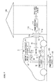
- FIG. 1 is a block diagram showing the structure of principal portions of an electric vehicle that is serving as a mobile power supply device according to a first embodiment of the present invention.
- an electric vehicle 1 is able to supply power to a power-receiving device 110 that is provided in that house 100, and is also able to charge a storage cell 11 with power that is supplied from a power-supplying device 120 that is installed on the ground at a distance of approximately 1 to 2 m from the house 100.
- the electric vehicle 1 is provided with a storage cell 11, a contactor 12 (i.e., a switching circuit), an inverter 13 (i.e., a drive circuit), a motor 14, a power-supplying coil 15, a power-supplying circuit 16 (i.e., a power converter), a power-receiving coil 17, a power-receiving circuit 18, and a charging device 19.
- the storage cell 11 and the charging device 19 are connected to a DC bus B1
- the inverter 13, the power supply circuit 16, the power-receiving circuit 18, and the charging device 19 are connected to a DC bus B2.
- the storage cell 11 is a cell that is mounted in the electric vehicle 1 and that is capable of being recharged (for example, a secondary cell such as a lithium-ion cell or a nickel hydrogen cell), and supplies power that is used to drive the motor 14.
- the contactor 12 is provided between the DC bus B1 and the DC bus B2 and, under the control of a control device (not shown) that is provided in the electric vehicle 1, switches the DC bus B1 and the DC bus B2 between a state in which they are connected together and a state in which they are disconnected from each other.
- the contactor 12 when power is discharged from the storage cell 11, the contactor 12 is controlled so that the DC bus B1 and the DC bus B2 are connected together so that, as a result of this, the storage cell 11, the inverter 13, the power supply circuit 16, and the power-receiving circuit 18 are connected.
- the contactor 12 when the storage cell 11 is charged, the contactor 12 is controlled so that the DC bus B1 and the DC bus B2 are disconnected from each other so that, as a result of this, the storage cell 11, the inverter 13, the power supply circuit 16, and the power-receiving circuit 18 are disconnected.
- the inverter 13 drives the motor 14 under the control of a control device (not shown) using power that is supplied via the contactor 12 from the storage cell 11.
- the motor 14 is mounted in the electric vehicle 1 so as to serve as a power generating source that generates motive power that is used to enable the electric vehicle 1 to move, and generates this motive power in accordance with the driving of the inverter 13.
- a motor such as permanent magnet synchronous motor, an induction motor and the like can be used as the motor 14.
- the inverter 13 it is also possible for the inverter 13 to convert regenerative power generated in the motor 14 into DC power, and then to charge the storage cell 11 using this DC power.
- the inverter 13 may also be a bi-directional power converter.
- the power-supplying coil 15 is provided in a rear portion of the electric vehicle 1, and is a coil that is used to wirelessly supply power from the storage cell 11 to the power-receiving device 110 that is provided in the house 100.
- An electromagnetic coupling circuit i.e., a first electromagnetic coupling circuit
- This electromagnetic coupling circuit refers to a circuit that supplies power wirelessly from the power-supplying coil 15 to the power-receiving coil 111 by electromagnetically coupling together the power-supplying coil 15 and the power-receiving coil 111.
- This electromagnetic coupling circuit may be either a circuit that supplies power by means of electromagnetic induction, or a circuit that supplies power by means of electromagnetic field resonance.
- the power-supplying coil 15 is provided in the rear portion of the electric vehicle 1 and is completely covered by a weatherproof cover 15a (i.e., a weatherproof component).
- the weatherproof cover 15a may be a cover that is provided in order to prevent the ingress of rainwater or foreign objects (for example insects) and the like into the power-supplying coil 15, or may be a cover that physically protects the power-supplying coil 15, and is formed from a resin that contains a high polymer material (for example, plastic, engineering plastic, or FRP (Fiber Reinforced Plastic)) that does not obstruct the wireless supply of power.
- the weatherproof cover 15a may be formed from a ceramic material that does not obstruct the wireless supply of power (for example, alumina, mullite, ferrite, forsterite, zirconia, zircon, cordierite, aluminum nitride, silicon nitride, silicon carbide, lead zirconate titanate, and conjugated compounds of these), and compounds of these with resins containing a high polymer material.
- these weatherproof covers 15a may be covered by a rubbery elastic body, or may be covered by a rubbery elastic body that is filled with a gas such as air or nitrogen.
- the power supply circuit 16 supplies power wirelessly from the storage cell 11 to the power-receiving device 110 via the electromagnetic coupling circuit that is formed by the power-supplying coil 15 and the power-receiving coil 111. Specifically, the power supply circuit 16 converts power (i.e., DC power) that is supplied from the storage cell 11 via the contactor 12 into AC power, and then supplies this to the power-supplying coil 15. As a result of this, the wireless supply of power to the power-receiving device 110 is achieved.
- power i.e., DC power
- the power-receiving coil 17 is provided in an underside portion of the electric vehicle 1, and is a coil that is used to wirelessly receive power (i.e., AC power) that is supplied from a power-supplying coil 121 that is provided in the power-supplying device 120 that is installed on the ground at a distance of approximately 1 to 2 meters from the house 100.
- An electromagnetic coupling circuit i.e., a second electromagnetic coupling circuit is formed by placing the power-receiving coil 17 adjacent to the power-supplying coil 121 of the power-supplying device 120.
- This electromagnetic coupling circuit refers to a circuit that supplies power wirelessly from the power-supplying coil 121 to the power-receiving coil 17 by electromagnetically coupling together the power-supplying coil 121 and the power-receiving coil 17.
- This electromagnetic coupling circuit may be either a circuit that supplies power by means of electromagnetic induction, or a circuit that supplies power by means of electromagnetic field resonance. Note that in FIG. 1 , a state is shown in which the power-receiving coil 17 is provided in the underside portion of the electric vehicle 1 in an uncovered state, however, it is also possible to provide the same type of cover as the weatherproof cover 15a that covers the power-supplying coil 15 so that the power-receiving coil 17 is completely covered.
- a cover that contains a high-strength alumina is preferred as there are cases in which the underside of the electric vehicle may be damaged while the vehicle is traveling by coming into contact with objects on the road, or by colliding with objects bouncing up from the road surface.
- these weather resistant covers 15a may be covered by a rubbery elastic body, or may be covered by a rubbery elastic body that is filled with a gas such as air or nitrogen.
- the power-receiving coil 18 receives power (i.e., AC power) that is supplied wirelessly via the electromagnetic coupling circuit that is formed by the power-supplying coil 121 of the power-supplying device 120 and by the power-receiving coil 17. It then converts the received power into DC power and then supplies it to the DC bus B2.
- the charging device 19 is a device that charges the storage cell 11 using power (i.e., DC power) that is supplied to it via the DC bus B2 from the power-receiving circuit 18.
- the power-receiving device 110 is provided with the power-receiving coil 111 that, together with the power-receiving coil 15 of the electric vehicle 1, forms an electromagnetic coupling circuit, and with a power-receiving circuit 112.
- the power-receiving coil 111 is attached to a wall surface of the house 100 at a height that is substantially the same as the height of the power-supplying coil 15, and it is completely covered by a weatherproof cover 111a of the same type as the weatherproof cover 15 a.
- the power-receiving circuit 112 receives power (i.e., AC power) wirelessly via the electromagnetic coupling circuit that is formed by the power-supplying coil 15 of the electric vehicle 1 and by the power-receiving coil 111. The power-receiving circuit 112 then converts the received power into DC power and supplies it to the interior of the house 100.
- power i.e., AC power
- the power-supplying device 120 is provided with the power-supplying coil 121 that, together with the power-receiving coil 17 of the electric vehicle 1, forms an electromagnetic coupling circuit, and with the power-supplying circuit 122.
- the power-supplying coil 121 is located in a position where it is adjacent to the power-receiving coil 17 of the electric vehicle 1 when the electric vehicle 1 has been parked next to the house 100 so that the power-supplying coil 15 and the power-receiving coil 111 of the power-receiving device 110 are adjacent to each other. Note that in the same way as the power-receiving coil 17 of the electric vehicle 1, it is also possible for the power-supplying coil 121 to be completely covered by a cover of the same type as the weatherproof cover 15a.
- the power-supplying circuit 122 wirelessly supplies AC power to the electric vehicle 1 via the electromagnetic coupling circuit that is formed by the power-supplying coil 121 and the power-receiving coil 17.
- FIGS. 2A through 2C are views illustrating operations according to the first embodiment of the present invention.
- FIG. 2A illustrates an operation performed when power is supplied to the house 100
- FIG. 2B illustrates an operation performed when the vehicle is traveling
- FIG. 2C illustrates an operation performed when the storage cell 11 is being charged.
- each of these operations will be described in sequence.
- a user drives the electric vehicle 1 backwards so that the rear portion of the electric vehicle 1 will be adjacent to the house 100 to which power is to be supplied.
- the user moves the electric vehicle 1 backwards, adjusting the position in the left right direction thereof so that the power-supplying coil 15 of the electric vehicle 1 will face the power-receiving coil 111 of the power-receiving device 110 that is provided in the house 100.
- the electric vehicle 1 is stopped. As a result of this, as is shown in FIG. 2A , an electromagnetic coupling circuit is formed by the power-supplying coil 15 of the electric vehicle 1 and by the power-receiving coil 111.
- the control device (not shown) provided in the electric vehicle 1 controls the contactor 12 so that the DC bus B1 and the DC bus B2 are connected together, and then causes the power-supplying circuit 16 to operate. At this time, the control device (not shown) stops the operations of the inverter 13, the power-receiving circuit 18, and the charging device 19.
- power stored in the storage cell 11 i.e., DC power
- the power-supplying circuit 16 via the contactor 12, and is converted into AC power.
- This converted AC power is then supplied to the power-supplying coil 15, and is then supplied wirelessly to the power-receiving device 110 via the electromagnetic coupling circuit that is formed by the power-supplying coil 15 and the power-receiving coil 111.
- the AC power supplied to the power-receiving device 110 is converted into DC power by the power-receiving circuit 112, and this converted DC power is then supplied to the interior of the house 100.
- the control device (not shown) provided in the electric vehicle 1 controls the contactor 12 so that the DC bus B1 and the DC bus B2 are connected together, and causes the inverter 13 to operate.
- the control device stops the operations of the power-supplying circuit 16, the power-receiving circuit 18, and the charging device 19.
- the power i.e., DC power
- the electric vehicle 1 starts to travel.
- the user drives the electric vehicle 1 backwards so that the rear portion of the electric vehicle 1 will be adjacent to the house 100 to which power is to be supplied.
- the electric vehicle 1 is stopped.
- an electromagnetic coupling circuit is formed by the power-receiving coil 17 of the electric vehicle 1 and by the power-supplying coil 121 provided in the power-supplying device 120.
- the control device (not shown) provided in the electric vehicle 1 controls the contactor 12 so that the DC bus B1 and the DC bus B2 are disconnected from each other, and then causes the power-receiving circuit 18 and the charging device 19 to operate. At this time, the control device (not shown) stops the operations of the inverter 13 and the power-supplying circuit 16.
- the AC power that is supplied from the power-supply circuit 122 of the power-supplying device 120 is supplied wirelessly to the electric vehicle 1 via the electromagnetic coupling circuit that is formed by the power-supplying coil 121 and the power-receiving coil 17.
- the AC power supplied to the electric vehicle 1 is received by the power-receiving circuit 18 and is converted into DC power.
- This converted DC power is then supplied to the charging device 19 and, as a result of this, the charging of the storage cell 11 takes place.
- the electric vehicle 1 is moved adjacent to the house 100 so that the power-supplying coil 15 of the electric vehicle 1 faces the power-receiving coil 111 of the power-receiving device 110 that is provided in the house 100.
- Power can be supplied to the house 100 as a result of this operation alone being performed.
- power can be supplied easily even if the user does not perform the task of fitting the plug of a cable either outside the vehicle or outside the house into a socket provided in the electric vehicle or in the house, as is the case in the conventional technology.
- the power-supplying coil 15 of the electric vehicle 1 and the power-receiving coil 111 of the power-receiving device 110 that is provided in the house 100 are completely covered respectively by the weatherproof covers 15a and 111a. Because of this, it is possible to prevent the ingress of rainwater or foreign objects (for example, insects) and the like into the power-supplying coil 15 and the power-receiving coil 111. As a result of this, because electrical connection faults do not occur, the task of maintenance can be performed easily.
- houses 100 that are either only able to receive a supply of power, or only able to supply power for charging a storage cell.
- houses 100 that are not provided with the power-supplying device 120 which includes the power-supplying coil 121, and that are only capable of supplying power from the electric vehicle 1 to the house 100 and not of charging the storage cell 11 of the electric vehicle 1.
- houses 100 that are not provided with the power-receiving device 110 which includes the power-receiving coil 111, and that are only capable of charging the storage cell 11 of the electric vehicle 1 and not of supplying power from the electric vehicle 1 to the house 100.
- FIG. 3 is a block diagram showing the structure of principal portions of an electric vehicle that is serving as a mobile power supply device according to a second embodiment of the present invention.
- the electric vehicle 1 described in the first embodiment supplies power to the house 100 and charges the storage cell 11 using mutually separate branches of circuit (i.e., a branch through the power-supplying coil 15 and the other through the power-receiving coil 17).
- these operations are performed by one and the same branch of circuit.
- the structure on the house 100 side is different from that of the first embodiment. Namely, the power-receiving device 110 that is provided in the house 100 is omitted, and a power-transferring device 130 is provided instead of the power-supplying device 120.
- the power-transferring device 130 is described below.
- the electric vehicle 2 is so constructed that the power-supplying coil 15 and the power-supplying circuit 16 of the electric vehicle 1 shown in FIG. 1 are omitted, and a power-transferring coil 21 and a power-transferring circuit 22 are provided respectively instead of the power-receiving coil 17 and the power-receiving circuit 18.
- the weatherproof cover 15a that is provided in the electric vehicle 1 is omitted, and a weatherproof cover 21a (i.e., a weatherproof component) that covers the power-transferring coil 21 is provided.
- the power-transferring coil 21 is provided in an underside portion of the electric vehicle 2, and is used to transmit or receive power (i.e., AC power) wirelessly between itself and a power-transferring coil 131 that is provided in the power-transferring device 130 that is installed on the ground.
- the power-transferring coil 21 is provided in the underside portion of the electric vehicle 2 so as to be completely covered by the weatherproof cover 21a which is similar to the above-described weatherproof cover 15 a.
- An electromagnetic coupling circuit is formed when the power-transferring coil 21 is positioned adjacent to the power-transferring coil 131 of the power-transferring device 130.
- the power-transferring circuit 22 supplies power from the storage cell 11 wirelessly to the power-transferring device 130 via the electromagnetic coupling circuit that is formed by the power-transferring coils 21 and 131. Moreover, the power-transferring circuit 22 also receives power that is supplied wirelessly from the power-transferring device 130 via the above-described electromagnetic coupling circuit. Specifically, the power-transferring circuit 22 converts power (i.e., DC power) that is supplied from the storage cell 11 via the contactor 12 into AC power, and then supplies it to the power-transferring coil 21. As a result of this, power can be supplied wirelessly to the power-transferring device 130. Moreover, the power-transferring circuit 22 also receives power (i.e., AC power) that is supplied to it from the power-transferring device 130, and converts this received power into DC power which it then supplies to the DC bus B2.
- power i.e., DC power
- the power-transferring device 130 is provided with a power-transferring coil 131 that, together with the power-transferring coil 21 of the electric vehicle 2, forms an electromagnetic coupling circuit, and with a power-transferring circuit 132.
- the power-transferring device 130 supplies power that it has received wirelessly from the electric vehicle 2 to the house 100, and also supplies power wirelessly to the electric vehicle 2.
- the power-transferring coil 131 is placed in the same position as the power-supplying coil 121 shown in FIG. 1 and is completely covered by the weatherproof cover 131a, which is the same type as the weatherproof cover 15a.
- the power-transferring circuit 132 supplies AC power wirelessly to the electric vehicle 2 via the electromagnetic coupling circuit that is formed by the power-transferring coils 21 and 131.
- the power-transferring circuit 132 receives the power that is supplied wirelessly from the electric vehicle 2 via the above-described electromagnetic coupling circuit.
- FIGs. 4A and 4B are views illustrating operations according to the second embodiment of the present invention.
- FIG. 4A illustrates an operation performed when power is supplied to the house 100
- FIG. 4B illustrates an operation performed when the storage cell 11 is being charged.
- each of these operations will be described in sequence.
- a user drives the electric vehicle 2 backwards so that the rear portion of the electric vehicle 2 will be adjacent to the house 100 to which power is to be supplied.
- the electric vehicle 2 is stopped.
- the left-right position of the electric vehicle 1 it was necessary to adjust the left-right position of the electric vehicle 1 so that the power-supplying coil 15 and the power-receiving coil 111 of the power-receiving device 110 that was provided in the house 100 would face each other.
- the left-right position of the electric vehicle 2 is adjusted so that the power-transferring coils 21 and 131 will face each other.
- an electromagnetic coupling circuit is formed by the power-transferring coils 21 and 131.
- the control device (not shown) provided in the electric vehicle 2 controls the contactor 12 so that the DC bus B1 and the DC bus B2 are connected together.
- the control device also operates the power-transferring circuit 22 so as to cause it to discharge power from the storage cell 11.
- the control device (not shown) stops the operations of the inverter 13 and the charging device 19.
- power stored in the storage cell 11 i.e., DC power
- DC power power stored in the storage cell 11
- This converted AC power is then supplied to the power-transferring coil 21, and is then supplied wirelessly to the power-transferring device 130 via the electromagnetic coupling circuit that is formed by the power-transferring coils 21 and 131.
- the AC power supplied to the power exchanging device 130 is converted into DC power by the power exchanging circuit 132, and this converted DC power is then supplied to the interior of the house 100.
- the user drives the electric vehicle 2 backwards so that the rear portion of the electric vehicle 2 will be adjacent to the house 100 to which power is to be supplied.
- the electric vehicle 2 is stopped.
- an electromagnetic coupling circuit is formed by the power-receiving coil 17 of the electric vehicle 1 and by the power-transferring coils 21 and 131.
- the control device (not shown) provided in the electric vehicle 2 controls the contactor 12 so that the DC bus B1 and the DC bus B2 are disconnected from each other, and then causes the power-transferring circuit 22 to operate so that it receives power supplied from the outside. At this time, the control device (not shown) stops the operations of the inverter 13 and causes the charging device 19 to operate.
- the AC power that is supplied from the power-transferring circuit 132 of the power-transferring device 130 is supplied wirelessly to the electric vehicle 2 via the electromagnetic coupling circuit that is formed by the power-transferring coils 21 and 131.
- the AC power supplied to the electric vehicle 2 is received by the power-transferring circuit 22 and is converted into DC power.
- This converted DC power is then supplied to the charging device 19 and, as a result of this, the charging of the storage cell 11 takes place.
- the control device (not shown) provided in the electric vehicle 2 controls the contactor 12 so that the DC bus B1 and the DC bus B2 are connected together, and causes the inverter 13 to operate.
- the control device stops the operations of the power-transferring circuit 22 and the charging device 19.
- the power i.e., DC power
- the electric vehicle 2 starts to travel as a result of the motor 14 then being driven by the inverter 13.
- the present embodiment simply by moving the electric vehicle 2 adjacent to the house 100 so that the power-transferring coil 21 of the electric vehicle 2 faces the power-transferring coil 131 of the power-transferring device 130, power can be supplied to the house 100.
- the power-transferring coil 21 of the electric vehicle 2 and the power-transferring coil 131 of the power-transferring device 130 are completely covered respectively by the weatherproof covers 21 a and 131 a. Because of this, it is possible to prevent the ingress of rainwater or foreign objects (for example, insects) and the like into the power-transferring coil 21 and the power-transferring coil 131. As a result of this, because electrical connection faults do not occur, the task of maintenance can be performed easily.
- FIG. 5 is a block diagram showing the structure of principal portions of an electric vehicle that is serving as a mobile power supply device according to a third embodiment of the present invention.
- the electric vehicle 1 according to the above-described first embodiment supplies power to the motor 14 and supplies power to the power-supplying coil 15 using mutually separate circuits, namely, the inverter 13 and the power-supplying circuit 16.
- an electric vehicle 3 of the present embodiment uses the converter 13 to supply power to both the motor 14 and the power-supplying coil 15.
- the electric vehicle 3 is so constructed that an inverter 31 (i.e., a power converter) is provided instead of the inverter 13 and the power-supplying circuit 16 of the electric vehicle 1 shown in FIG. 1 , and that a first contactor 32 and a second contactor 33 are provided.
- an inverter 31 i.e., a power converter
- the inverter 31 converts the power (i.e., DC power) supplied from the storage cell 11 into three-phase or two-phase AC power based on gate signals that are input from a gate drive circuit 35 (described below referring to FIG. 6 ).
- this three-phase AC power i.e., U phase, V phase, and W phase AC power
- the power is instead to be supplied to the house 100 (i.e., when the inverter 31 is connected to the power-supplying coil 15 by the second contactor 33)
- two-phase AC power i.e., U phase and V phase AC power
- the inverter 31 may also be a bi-directional power converter.
- the first contactor 32 is provided between the inverter 31 and the motor 14 and, under the control of a control unit 36 (described below referring to FIG. 6 ), switches the state of connection between the inverter 31 and the motor 14 between a connected state and a disconnected state. Specifically, when the electric vehicle 3 is traveling, the first contactor 32 changes to a closed state in order to connect the inverter 31 to the motor 14, and when the electric vehicle 3 is stopped, changes to an open state in order to disconnect the inverter 31 from the motor 14.
- the second contactor 33 is provided between the inverter 31 and the power-supplying coil 15 and, under the control of the control unit 56 (described below referring to FIG. 6 ) switches the state of connection between the inverter 13 and the power-supplying coil 15 between a connected state and a disconnected state. Specifically, when power is being supplied to the house 100, the second contactor 33 changes to a closed state in order to connect the inverter 31 to the power-supplying coil 15, and when the supply of power to the house 100 is stopped, changes to an open state in order to disconnect the inverter 31 from the power-supplying coil 15.
- FIG. 6 is a view showing in detail a control system of the electric vehicle 3 and also the components that are controlled by this control system according to the third embodiment. Note that in FIG. 6 , the same symbol is attached to a component that is the same as the component shown in FIG. 5 . Moreover, in order to make the diagrams easier to view, the contactor 12 that is located between the storage cell 11 and the inverter 13 has been omitted from FIG. 6 through FIG. 8 . As is shown in FIG.
- the inverter 31 of the above-described electric vehicle 3 is realized by a circuit in which three switching legs L1, L2, and L3 that are used to output U-phase, V-phase, and W-phase AC power are connected together in parallel (i.e., by a circuit that is comprised of two transistors that are connected together in series, and a diode that is connected in parallel to each of these two transistors).
- IGBT Insulated Gate Bipolar Transistors
- power MOSFET Metal-Oxide-Semiconductor Field-Effect Transistors
- the inverter 31 is also provided with a smoothing circuit that is formed by a smoothing reactor and a smoothing capacitor and is located between the switching legs L1, L2, and L3 and the storage cell 11.
- the power-supplying coil 15 is provided with a coil 15b and two capacitors 15c.
- the capacitors 15c together with the coil 15b form a series resonant circuit.
- One end of the coil 15b is connected to the switching leg L1 via one of the capacitors 15c and the second contactor 33, while the other end of the coil 15b is connected to the switching leg L2 of the inverter 31 via the other capacitor 15c and the second contactor 33.
- the coil 15b is completely covered by the weatherproof cover 15a.
- the electric vehicle 3 is also provided with a rotation (i.e. angle) detector 34, a gate drive circuit 35, and a control unit 36.
- a rotation (i.e. angle) detector 34 detects the rotation of the electric vehicle 3 and controls the gate drive circuit 35.
- the control unit 36, the first contactor 32, and the second contactor 33 form the power supply destination setting device of the present embodiment.
- the rotation detector 34 is a sensor that detects the rotation of the motor 14, and outputs a detection signal to the control unit 36.
- the rotation detector 34 detects the rotation angle when the motor 14 is rotating using an encoder, and outputs to the control unit 36b a pulse signal which contains a predetermined number of pulses (for example, 65536 pulses) per one rotation of the rotor of the motor 14.
- the gate drive circuit 35 is provided between the inverter 31 and the control unit 36, and converts the voltage of gate signals that are input from the control unit 36, and then outputs the result to the inverter 31. Moreover, because the gate drive circuit 35 is provided between the inverter 31 and the control unit 36, it also has the role of insulating the inverter 31 from the control unit 36.
- the control unit 36 is comprised of a microcontroller or the like, and controls the inverter 31, the first contactor 32, and the second contactor 33 based on control programs that are stored in it. For example, when a travel command is input by an operation of the driver via an operating device (not shown), the control unit 36 controls the first contactor 32 so that the inverter 31 and the motor 14 are connected to each other. If, on the other hand, a power-supply command is input by the operation of the driver via the operating device, the control unit 36 controls the second contactor 33 so that the inverter 31 and the power-supplying coil 15 are connected to each other.
- This control unit 36 is provided with three functional components, namely, a motor control unit 36a, a wireless power supply control unit 36b, and a gate signal selection unit 36c, that correspond to operations of the microcontroller to control the inverter 31.
- the motor control unit 36a When a travel command is input by an operation of the driver via an operating device (not shown), in order to create in the inverter 31 the three-phase AC power (i.e., U-phase, V-phase, and W-phase AC power) that is used to drive the motor 14 to rotate, the motor control unit 36a creates a gate signal that corresponds to the U-phase, V-phase, and W-phase AC power, and outputs this gate signal to the gate signal selection unit 36c at the same time as it monitors detection results from the rotation detector 34.
- the three-phase AC power i.e., U-phase, V-phase, and W-phase AC power
- the wireless power supply control unit 36b When a power supply command is input by an operation of the driver via the operating device, in order to create in the inverter 31 the two-phase AC power (i.e., U-phase and V-phase AC power) that is used to supply power to the power-supplying coil 15, the wireless power supply control unit 36b creates a gate signal that corresponds to the U-phase and V-phase AC power, and outputs this gate signal to the gate signal selection unit 36c. At this time, the wireless power supply control unit 36b keep the transistor of the switching leg L3 of the inverter 31 OFF without creating a gate signal that corresponds to the W-phase AC power.
- U-phase and V-phase AC power i.e., U-phase and V-phase AC power
- the gate signal selection unit 36c selects either the gate signal input from the motor control unit 36a or the gate signal input from the wireless power supply control unit 36b, and outputs the selected gate signal to the gate drive circuit 35. Namely, if a travel command is input by an operation of the driver via an operating device, the gate signal selection unit 36c only outputs the gate signal from the motor control unit 36a to the gate drive circuit 35, and if a power supply command is input by an operation of the driver via the operating device, the gate signal selection unit 36c only outputs the gate signal from the wireless power supply control unit 36b to the gate drive circuit 35.
- the power-receiving coil 111 of the house 100 is provided with a coil 111b and the capacitors 111c.
- the capacitor 111c is connected in parallel between the coil 111b and the power-receiving circuit 112. Note that although not shown in FIG. 6 , the coil 111b is completely covered by a weatherproof cover 111a.
- FIG. 7 and FIG. 8 are views illustrating operations of the third embodiment of the present invention. Note that FIG. 7 is a view illustrating an operation that is performed when electric vehicle 3 is traveling, while FIG. 8 is a view illustrating an operation that is performed when power is supplied to the house 100. Hereinafter, each of these operations will be described in sequence.
- the control unit 36 switches the first contactor 32 to a closed state so that the motor 14 and the inventor 31 are connected together, and also switches the second contactor 33 to an open state so that the power-supplying coil 15 and the inverter 31 are disconnected from each other.
- the motor control unit 36a of the control unit 36 creates in the inverter 31 the gate signal that is required to create the three-phase AC power (i.e., the U-phase, the V-phase, and the W-phase AC power) that is used to drive the motor 14 to rotate at the desired rotation speed, and then outputs this gate signal to the gate signal selection unit 36c.
- the gate signal selection unit 36c selects only the gate signal input from the motor control unit 36a, and outputs it to the gate drive circuit 35.
- the gate drive circuit 35 converts the voltage of the gate signal that was input from the gate signal selection unit 36c, and then outputs it to the inverter 31.
- the inverter 31 creates three-phase AC power (i.e., U-phase, V-phase, and W-phase AC power) from the power
- the DC power stored in the storage cell 11 based on the gate signal input from the gate drive circuit 35, and supplies the created three-phase AC power to the motor 14.
- the motor 14 being driven by the power supplied from the inverter 31, the electric vehicle 3 starts to travel.
- a user drives the electric vehicle 3 so as to move the electric vehicle 3 backwards so that the rear portion of the electric vehicle 3 will be adjacent to the house 100 to which power is to be supplied.
- the electric vehicle 3 is stopped.
- the user moves the electric vehicle 3 backwards while at the same time adjusting the position in the left right direction thereof so that the power-supplying coil 15 of the electric vehicle 3 will face the power-receiving coil 111 of the power-receiving device 110 that is provided in the house 100.
- the electric vehicle 3 is stopped.
- the control unit 36 switches the first contactor 32 to an open state so that the motor 14 and the inverter 31 are disconnected from each other, and also switches the second contactor 33 to a closed state so that the power-supplying coil 15 and the inverter 31 are connected to each other.
- the wireless power supply control unit 36b of the control unit 36 creates in the inverter 31 the gate signal that is required to create the two-phase AC power (i.e., the U-phase and the V-phase AC power) that is to be supplied to the power-supplying coil 15, and outputs this gate signal to the gate signal selection unit 36c.
- the gate signal selection unit 36c selects only the gate signal input from the wireless power supply control unit 36b, and outputs it to the gate drive circuit 35.
- the gate drive circuit 35 converts the voltage of the gate signal input from the gate signal selection unit 36c, and then outputs it to the inverter 31.
- the inverter 31 creates two-phase AC power (i.e., U-phase power and V-phase power) from the power (i.e., the DC power) stored in the storage cell 11 based on the gate signal that was input from the gate drive circuit 35, and then supplies this two-phase AC power to the power-supplying coil 15.
- AC power is supplied wirelessly to the power-receiving device 110 via an electromagnetic coupling circuit that is formed by the power-supplying coil 15 and the power-receiving coil 111.
- the AC power supplied to the power-receiving device 110 is converted into DC power by the power-receiving circuit 112, and this converted DC power is then supplied to the interior of the house 100.
- the electric vehicle 3 is moved adjacent to the house 100 so that the power-supplying coil 15 of the electric vehicle 3 faces the power-receiving coil 111 of the power-receiving device 110 that is provided in the house 100.
- Power can be supplied to the house 100 as a result of this operation alone being performed.
- power can be supplied easily even if the user does not perform the task of fitting the plug of a cable either outside the vehicle or outside the house into a socket provided in the electric vehicle or in the house, as is the case in the conventional technology.
- the power-supplying coil 15 of the electric vehicle 3 and the power-receiving coil 111 of the power-receiving device 110 that is provided in the house 100 are completely covered respectively by the weatherproof covers 15a and 111a. Because of this, it is possible to prevent the ingress of rainwater or foreign objects (for example, insects) and the like into the power-supplying coil 15 and the power-receiving coil 111. As a result of this, because electrical connection faults do not occur, the task of maintenance can be performed easily. Furthermore, in the present embodiment, because the inverter 31 can be used to supply power to both the motor 14 and the power-supplying coil 15, the manufacturing costs of the electric vehicle 3 can be reduced.
- a mobile power supply device and method have been described above based on embodiments of the present invention, however, the present invention is not limited to the above-described embodiments and can be altered freely within the range of the present invention.
- a description is given of a mobile power supply device that is able to both supply power wirelessly to the outside and perform charging using power that is supplied wirelessly from the outside, however, it is also possible for the present invention to be applied to a mobile power supply device that is only able to supply power wirelessly to the outside.
- the power-supplying coil 15 and power-receiving coil 111, and the power-receiving coil 17 and power-supplying coil 121 of the first and third embodiments are placed in positions adjacent to each other where they are able to transfer power wirelessly, then the locations where they are installed can be arbitrarily chosen.
- the power-supplying coil 121 can be provided in the house 100, while the power-receiving coil 111 may also be provided on the ground.
- the power-receiving coil 17 or the power-supplying coil 15 is placed in an appropriate position in the electric vehicles 1 or 3, namely, in a position where the coils are adjacent to each other when the vehicle is stopped and power is able to be transferred wirelessly.
- the power-transferring coil 131 may be provided in the house 100, and for the power-transferring coil 21 to be placed in the rear portion of the electric vehicle 2. Furthermore, the coil may also be provided in the side surface or front surface of the electric vehicles 1 through 3.
- the object to be supplied with power is an electric vehicle in which a storage cell has been installed.
- the present invention can also be applied to plug-in hybrid vehicles, and to transporting vehicles and the like.
- the present invention can also be applied to driverless moving vehicles.
- the power-receiving circuit 112 that is provided in the power-receiving device 110 of the house 100 shown in FIG. 1 and FIG. 5 , and the power-transferring circuit 132 that is provided in the power-transferring device 130 shown in FIG. 3 require a small-capacity power supply that is used to drive their internal control circuits.
- this small-capacity power supply it is possible to use a power generator that generates power using natural energy such as sunlight or wind power or the like, and it is also possible to use a small-sized storage cell. If a small-sized storage cell is used, then it is desirable that it is charged using power supplied from the electric vehicles 1 through 3.
- control circuits provided internally in the power-receiving circuit 112 shown in FIG. 1 and FIG. 5 and in the power-transferring circuit 132 shown in FIG. 3 to be driven using power supplied from the electric vehicles 1 through 3.
- the aforementioned power generator and small-sized storage cell can be omitted, and this makes the present invention suitable for supplying power to houses where it is normally difficult to perform maintenance such as emergency shelters and the like.
- the electric vehicles 1 through 3 when power is being supplied from the electric vehicles 1 through 3 to the house 100, it is also possible for the electric vehicles 1 through 3 to receive information about the power-receiving conditions from the house 100 by means of wireless communication or the like, and for the power-receiving conditions of the house 100 to be improved by adjusting the frequency of the AC power in accordance with the power-receiving conditions.
- the mobile power supply device of the present invention it is possible to easily supply power without having to perform the task of connecting a cable. Moreover, no electrical connection faults occur in the power-supplying coil that is covered by a weatherproof component. As a result, the task of maintaining the power-supplying coil can be performed easily.
Landscapes
- Engineering & Computer Science (AREA)
- Power Engineering (AREA)
- Mechanical Engineering (AREA)
- Transportation (AREA)
- Life Sciences & Earth Sciences (AREA)
- Sustainable Development (AREA)
- Sustainable Energy (AREA)
- Computer Networks & Wireless Communication (AREA)
- Chemical & Material Sciences (AREA)
- Combustion & Propulsion (AREA)
- Electric Propulsion And Braking For Vehicles (AREA)
- Charge And Discharge Circuits For Batteries Or The Like (AREA)
Abstract
Description
- The present invention relates to a mobile power supply device that is capable of supplying power externally of itself
- Priority is claimed on Japanese Patent Application No.
2011-257944, filed November 25, 2011 - Conventionally, it is common for various vehicles such as automobiles and transporting vehicles to be equipped with a combustion engine as a power generating source. However, in recent years, in order to achieve the ideal of a low-carbon society, vehicles that are equipped with an electric motor instead of a combustion engine as a power generating source, or vehicles that are equipped with both a combustion engine and an electric motor as a power source are becoming increasingly common. Such vehicles are equipped with rechargeable batteries (for example, secondary cells such as lithium ion cells or nickel hydrogen cells or the like) that are rechargeable and that supply power to drive the electric motor, and are so constructed that the storage cells can be charged by power supplied from an external power supply device.
- For example, in an electric vehicle (EV) that uses an electric motor exclusively as a power generating source, the charging of the storage cells is performed using power that is supplied from an external power supply device. Furthermore, among hybrid vehicles (HV) in which both a combustion engine and an electric motor combine to serve as a power generating source, in those hybrid vehicles that are known as plug-in hybrid vehicles, the charging of the storage cells can be performed using power supplied from an external power supply device in the same way as in an electric vehicle.
- Vehicles such as the above-described electric vehicles and hybrid vehicles and the like are used as transportation means. Because of this, they are usually so constructed that the power to be supplied to the motor is charged to a storage cell using power that is supplied from the external power supply device. In contrast to this, in
Patent documents 1 through 3 (see below), technology is disclosed that makes it possible to supply power from the storage cells that are installed in the electric vehicle to the outside (for example, to a house). Specifically, in the technology disclosed in these documents, an electric vehicle that has been parked adjacent to the house is connected to a house by a cable, and power is supplied to the house from the electric vehicle via this cable. -
- [Patent document 1] Japanese Patent Application Laid-Open (JP-A) No.
2011-55589 - [Patent document 2] Japanese Patent Application Laid-Open (JP-A) No.
2010-172068 - [Patent document 3] Japanese Patent Application Laid-Open (JP-A) No.
2006-158084 - However, in the technology disclosed in the
aforementioned Patent documents 1 through 3, in order to supply power from an electric vehicle to a house, it is necessary to connect the electric vehicle and the house together electrically by means of a cable. In order to make this connection, it is necessary for the cable plugs to be engaged with the sockets provided in the house and the electric vehicle. However, it is difficult for this engagement to be performed automatically without any human intervention, so that it is necessary for a user to perform this engagement manually. - Because the aforementioned plugs and sockets are provided either outside the vehicle or outside the house, it is easy for electrical connection faults such as poor connections or short-circuiting and the like to occur due to the ingress of rainwater or foreign objects (for example insects) and the like. Moreover, as is described above, because it is necessary for the cable to be connected manually by a user, in some cases this task must be performed in an unpleasant environment (for example, in a cold environment, or a hot environment, or a dark environment) either outside the vehicle or outside the house.
- If the aforementioned task is only performed a few times, then the task is not overly arduous. However, in cases such as when, for example, a user has to perform the task at several dozen or more uninhabited houses while also having to supply power for illumination at each one, then the user must perform the aforementioned task each time they arrive at one of the houses on their round. Because of this, the task does become extremely burdensome.
- The present invention was conceived in view of the above-described circumstances, and it is an object thereof to provide a mobile power supply device that makes it possible to easily supply power without causing any electrical connection faults to occur.
- In order to solve the above-described problems, a mobile power supply device according to a first aspect of the present invention is a mobile power supply device (1 or 3) that is capable of supplying power stored in a storage cell (11) to the outside, and that includes: a power-supplying coil (15) that is covered by a weatherproof component (15a) and that, together with an external power-receiving coil (111), forms a first electromagnetic coupling circuit; and a power converter (16 or 31) that converts DC power stored in the storage cell into AC power and then supplies the AC power to the power-supplying coil.
- Moreover, according to a mobile power supply device according to a second aspect of the present invention in the above-described first aspect, there are provided: a power-receiving coil (17) that, together with an external power-receiving coil (121), forms a second electromagnetic coupling circuit; a power-receiving circuit (18) that receives power that is supplied wirelessly from the outside via the second electromagnetic coupling circuit that is formed by the external power-supplying coil and the power-receiving coil; and a charging device (19) that charges the storage cell using power received by the power-receiving circuit.
- Moreover, according to a mobile power supply device according to a third aspect of the present invention in the above-described second aspect, the power-receiving coil is covered by a weatherproof component.
- Moreover, according to a mobile power supply device according to a fourth aspect of the present invention in the above-described second aspect, there are provided: a motor (14) that generates power used for movement; a drive circuit (13) that drives the motor using power stored in the storage cell; and a switching circuit (12) that switches between connecting the power-supplying circuit, the power-receiving circuit, and the drive circuit to the storage cell and disconnecting them from the storage cell.
- Moreover, according to a mobile power supply device according to a fifth aspect of the present invention in the above-described second or third aspects, there are provided: a motor (14) that generates power used for movement; and a power supply destination setting device (32, 33, 35, and 36) that sets the destination for the supply of AC power output from the power converter (31) to either the power-supplying coil or the motor.
- In order to solve the above-described problems, a mobile power supply device according to a sixth aspect of the present invention is a mobile power supply device (2) that is capable of supplying power stored in a storage cell (11) to the outside, and that includes: a power-transferring coil (21) that is covered by a weatherproof component (21a) and that, together with an external power-transferring coil, forms an electromagnetic coupling circuit; and a power-transferring circuit (22) that, out of a first operation in which power that is stored in the storage cell is supplied wirelessly to the outside via the electromagnetic coupling circuit, and a second operation in which power that is supplied wirelessly from the outside via the electromagnetic coupling circuit is received, performs at least the first operation.
- Moreover, according to a mobile power supply device according to a seventh aspect of the present invention in the above-described sixth aspect, there is provided a charging device (19) that, when the second operation is performed by the power-transferring circuit, charges the storage cell using power received by the power-transferring circuit.
- Moreover, according to a mobile power supply device according to an eighth aspect of the present invention in the above-described sixth or seventh aspects, there are provided: a motor (14) that generates power that is used for movement; a drive circuit (13) that drives the miter using power stored in the storage cell; and a switching circuit (12) that switches between connecting the power-transferring circuit and the drive circuit to the storage cell, and disconnecting them from the storage cell.
- According to the present invention, when a first electromagnetic coupling circuit is formed by a power-supplying coil that is covered by a weatherproof component and by an external power-receiving coil, then the power accumulated in a storage cell is supplied to the outside wirelessly via this first electromagnetic coupling circuit. Because of this, the effect is obtained that it is possible to easily supply power without having to perform the task of connecting a cable. Moreover, because the power-supplying coil is covered by a weatherproof component, no electrical connection faults occur. As a result, the effect is obtained that maintenance is easy.
-
-
FIG. 1 is a block diagram showing the structure of principal portions of an electric vehicle that is serving as a mobile power supply device according to a first embodiment of the present invention. -
FIG. 2A is a view illustrating an operation of the first embodiment of the present invention. -
FIG. 2B is a view illustrating an operation of the first embodiment of the present invention. -
FIG. 2C is a view illustrating an operation of the first embodiment of the present invention. -
FIG. 3 is a block diagram showing the structure of principal portions of an electric vehicle that is serving as a mobile power supply device according to a second embodiment of the present invention. -
FIG. 4A is a view illustrating an operation of the second embodiment of the present invention. -
FIG. 4B is a view illustrating an operation of the second embodiment of the present invention. -
FIG. 5 is a block diagram showing a general outline of an electric vehicle that is serving as a mobile power supply device according to a third embodiment of the present invention. -
FIG. 6 is a view showing in detail a control system as well as components that are controlled by that control system according to the third embodiment of the present invention. -
FIG. 7 is a view illustrating an operation of the third embodiment of the present invention. -
FIG. 8 is a view illustrating an operation of the third embodiment of the present invention. - Hereinafter, a mobile power supply device according to embodiments of the present invention will be described with reference made to the drawings. Note that, hereinafter, an example of a case in which the mobile electric supply device is an electric vehicle that uses only a motor as a power generating source will be described.
-
FIG. 1 is a block diagram showing the structure of principal portions of an electric vehicle that is serving as a mobile power supply device according to a first embodiment of the present invention. As is shown inFIG. 1 , while being parked adjacent to ahouse 100, anelectric vehicle 1 is able to supply power to a power-receivingdevice 110 that is provided in thathouse 100, and is also able to charge astorage cell 11 with power that is supplied from a power-supplyingdevice 120 that is installed on the ground at a distance of approximately 1 to 2 m from thehouse 100. - The
electric vehicle 1 is provided with astorage cell 11, a contactor 12 (i.e., a switching circuit), an inverter 13 (i.e., a drive circuit), amotor 14, a power-supplyingcoil 15, a power-supplying circuit 16 (i.e., a power converter), a power-receiving coil 17, a power-receiving circuit 18, and acharging device 19. Thestorage cell 11 and the chargingdevice 19 are connected to a DC bus B1, and theinverter 13, thepower supply circuit 16, the power-receivingcircuit 18, and the chargingdevice 19 are connected to a DC bus B2. - The
storage cell 11 is a cell that is mounted in theelectric vehicle 1 and that is capable of being recharged (for example, a secondary cell such as a lithium-ion cell or a nickel hydrogen cell), and supplies power that is used to drive themotor 14. Thecontactor 12 is provided between the DC bus B1 and the DC bus B2 and, under the control of a control device (not shown) that is provided in theelectric vehicle 1, switches the DC bus B1 and the DC bus B2 between a state in which they are connected together and a state in which they are disconnected from each other. - Specifically, when power is discharged from the
storage cell 11, thecontactor 12 is controlled so that the DC bus B1 and the DC bus B2 are connected together so that, as a result of this, thestorage cell 11, theinverter 13, thepower supply circuit 16, and the power-receivingcircuit 18 are connected. In contrast to this, when thestorage cell 11 is charged, thecontactor 12 is controlled so that the DC bus B1 and the DC bus B2 are disconnected from each other so that, as a result of this, thestorage cell 11, theinverter 13, thepower supply circuit 16, and the power-receivingcircuit 18 are disconnected. - The
inverter 13 drives themotor 14 under the control of a control device (not shown) using power that is supplied via thecontactor 12 from thestorage cell 11. Themotor 14 is mounted in theelectric vehicle 1 so as to serve as a power generating source that generates motive power that is used to enable theelectric vehicle 1 to move, and generates this motive power in accordance with the driving of theinverter 13. A motor such as permanent magnet synchronous motor, an induction motor and the like can be used as themotor 14. Moreover, it is also possible for theinverter 13 to convert regenerative power generated in themotor 14 into DC power, and then to charge thestorage cell 11 using this DC power. Namely, theinverter 13 may also be a bi-directional power converter. - The power-supplying
coil 15 is provided in a rear portion of theelectric vehicle 1, and is a coil that is used to wirelessly supply power from thestorage cell 11 to the power-receivingdevice 110 that is provided in thehouse 100. An electromagnetic coupling circuit (i.e., a first electromagnetic coupling circuit) is formed by placing the power-supplyingcoil 15 adjacent to a power-receivingcoil 111 that is provided in the power-receivingdevice 110. This electromagnetic coupling circuit refers to a circuit that supplies power wirelessly from the power-supplyingcoil 15 to the power-receivingcoil 111 by electromagnetically coupling together the power-supplyingcoil 15 and the power-receivingcoil 111. This electromagnetic coupling circuit may be either a circuit that supplies power by means of electromagnetic induction, or a circuit that supplies power by means of electromagnetic field resonance. - The power-supplying
coil 15 is provided in the rear portion of theelectric vehicle 1 and is completely covered by aweatherproof cover 15a (i.e., a weatherproof component). Theweatherproof cover 15a may be a cover that is provided in order to prevent the ingress of rainwater or foreign objects (for example insects) and the like into the power-supplyingcoil 15, or may be a cover that physically protects the power-supplyingcoil 15, and is formed from a resin that contains a high polymer material (for example, plastic, engineering plastic, or FRP (Fiber Reinforced Plastic)) that does not obstruct the wireless supply of power. Alternatively, theweatherproof cover 15a may be formed from a ceramic material that does not obstruct the wireless supply of power (for example, alumina, mullite, ferrite, forsterite, zirconia, zircon, cordierite, aluminum nitride, silicon nitride, silicon carbide, lead zirconate titanate, and conjugated compounds of these), and compounds of these with resins containing a high polymer material. Alternatively, in order to physically protect the power-supplyingcoil 15, theseweatherproof covers 15a may be covered by a rubbery elastic body, or may be covered by a rubbery elastic body that is filled with a gas such as air or nitrogen. - The
power supply circuit 16 supplies power wirelessly from thestorage cell 11 to the power-receivingdevice 110 via the electromagnetic coupling circuit that is formed by the power-supplyingcoil 15 and the power-receivingcoil 111. Specifically, thepower supply circuit 16 converts power (i.e., DC power) that is supplied from thestorage cell 11 via thecontactor 12 into AC power, and then supplies this to the power-supplyingcoil 15. As a result of this, the wireless supply of power to the power-receivingdevice 110 is achieved. - The power-receiving
coil 17 is provided in an underside portion of theelectric vehicle 1, and is a coil that is used to wirelessly receive power (i.e., AC power) that is supplied from a power-supplyingcoil 121 that is provided in the power-supplyingdevice 120 that is installed on the ground at a distance of approximately 1 to 2 meters from thehouse 100. An electromagnetic coupling circuit (i.e., a second electromagnetic coupling circuit) is formed by placing the power-receivingcoil 17 adjacent to the power-supplyingcoil 121 of the power-supplyingdevice 120. - This electromagnetic coupling circuit refers to a circuit that supplies power wirelessly from the power-supplying
coil 121 to the power-receivingcoil 17 by electromagnetically coupling together the power-supplyingcoil 121 and the power-receivingcoil 17. This electromagnetic coupling circuit may be either a circuit that supplies power by means of electromagnetic induction, or a circuit that supplies power by means of electromagnetic field resonance. Note that inFIG. 1 , a state is shown in which the power-receivingcoil 17 is provided in the underside portion of theelectric vehicle 1 in an uncovered state, however, it is also possible to provide the same type of cover as theweatherproof cover 15a that covers the power-supplyingcoil 15 so that the power-receivingcoil 17 is completely covered. In particular, a cover that contains a high-strength alumina (Al2O3) is preferred as there are cases in which the underside of the electric vehicle may be damaged while the vehicle is traveling by coming into contact with objects on the road, or by colliding with objects bouncing up from the road surface. - Furthermore, in order to physically protect the power-receiving
coil 17, these weatherresistant covers 15a may be covered by a rubbery elastic body, or may be covered by a rubbery elastic body that is filled with a gas such as air or nitrogen. - The power-receiving
coil 18 receives power (i.e., AC power) that is supplied wirelessly via the electromagnetic coupling circuit that is formed by the power-supplyingcoil 121 of the power-supplyingdevice 120 and by the power-receivingcoil 17. It then converts the received power into DC power and then supplies it to the DC bus B2. The chargingdevice 19 is a device that charges thestorage cell 11 using power (i.e., DC power) that is supplied to it via the DC bus B2 from the power-receivingcircuit 18. - Next, a brief description of the power-receiving
device 110 that is provided in thehouse 100, and of the power-supplyingdevice 120 that is installed on the ground at a distance of approximately 1 to2 meters from thehouse 100 will be given. The power-receivingdevice 110 is provided with the power-receivingcoil 111 that, together with the power-receivingcoil 15 of theelectric vehicle 1, forms an electromagnetic coupling circuit, and with a power-receivingcircuit 112. The power-receivingcoil 111 is attached to a wall surface of thehouse 100 at a height that is substantially the same as the height of the power-supplyingcoil 15, and it is completely covered by aweatherproof cover 111a of the same type as theweatherproof cover 15 a. - The power-receiving
circuit 112 receives power (i.e., AC power) wirelessly via the electromagnetic coupling circuit that is formed by the power-supplyingcoil 15 of theelectric vehicle 1 and by the power-receivingcoil 111. The power-receivingcircuit 112 then converts the received power into DC power and supplies it to the interior of thehouse 100. - The power-supplying
device 120 is provided with the power-supplyingcoil 121 that, together with the power-receivingcoil 17 of theelectric vehicle 1, forms an electromagnetic coupling circuit, and with the power-supplyingcircuit 122. The power-supplyingcoil 121 is located in a position where it is adjacent to the power-receivingcoil 17 of theelectric vehicle 1 when theelectric vehicle 1 has been parked next to thehouse 100 so that the power-supplyingcoil 15 and the power-receivingcoil 111 of the power-receivingdevice 110 are adjacent to each other. Note that in the same way as the power-receivingcoil 17 of theelectric vehicle 1, it is also possible for the power-supplyingcoil 121 to be completely covered by a cover of the same type as theweatherproof cover 15a. The power-supplyingcircuit 122 wirelessly supplies AC power to theelectric vehicle 1 via the electromagnetic coupling circuit that is formed by the power-supplyingcoil 121 and the power-receivingcoil 17. - Next, operations of the
electric vehicle 1 having the above-described structure will be described.FIGS. 2A through 2C are views illustrating operations according to the first embodiment of the present invention.FIG. 2A illustrates an operation performed when power is supplied to thehouse 100,FIG. 2B illustrates an operation performed when the vehicle is traveling, andFIG. 2C illustrates an operation performed when thestorage cell 11 is being charged. Hereinafter, each of these operations will be described in sequence. - Firstly, a user drives the
electric vehicle 1 backwards so that the rear portion of theelectric vehicle 1 will be adjacent to thehouse 100 to which power is to be supplied. The user moves theelectric vehicle 1 backwards, adjusting the position in the left right direction thereof so that the power-supplyingcoil 15 of theelectric vehicle 1 will face the power-receivingcoil 111 of the power-receivingdevice 110 that is provided in thehouse 100. Once theelectric vehicle 1 has been moved backwards to a position where power is able to be supplied to thehouse 100, theelectric vehicle 1 is stopped. As a result of this, as is shown inFIG. 2A , an electromagnetic coupling circuit is formed by the power-supplyingcoil 15 of theelectric vehicle 1 and by the power-receivingcoil 111. - Next, when the user issues a power supply command to the
electric vehicle 1 while theelectric vehicle 1 is stopped, the supply of power to thehouse 100 is started. Specifically, when the user issues a power supply command, the control device (not shown) provided in theelectric vehicle 1 controls thecontactor 12 so that the DC bus B1 and the DC bus B2 are connected together, and then causes the power-supplyingcircuit 16 to operate. At this time, the control device (not shown) stops the operations of theinverter 13, the power-receivingcircuit 18, and the chargingdevice 19. - As a result of this, as is shown in
FIG. 2A , power stored in the storage cell 11 (i.e., DC power) is supplied to the power-supplyingcircuit 16 via thecontactor 12, and is converted into AC power. This converted AC power is then supplied to the power-supplyingcoil 15, and is then supplied wirelessly to the power-receivingdevice 110 via the electromagnetic coupling circuit that is formed by the power-supplyingcoil 15 and the power-receivingcoil 111. The AC power supplied to the power-receivingdevice 110 is converted into DC power by the power-receivingcircuit 112, and this converted DC power is then supplied to the interior of thehouse 100. - When the user starts driving the
electric vehicle 1, the control device (not shown) provided in theelectric vehicle 1 controls thecontactor 12 so that the DC bus B1 and the DC bus B2 are connected together, and causes theinverter 13 to operate. At this time, the control device (not shown) stops the operations of the power-supplyingcircuit 16, the power-receivingcircuit 18, and the chargingdevice 19. As a result of this, as is shown inFIG. 2B , the power (i.e., DC power) stored in thestorage cell 11 is supplied to theinverter 13 via thecontactor 12. As a result of themotor 14 then being driven by theinverter 13, theelectric vehicle 1 starts to travel. - In the same way as the above-described operation performed when power is supplied to the
house 100, the user drives theelectric vehicle 1 backwards so that the rear portion of theelectric vehicle 1 will be adjacent to thehouse 100 to which power is to be supplied. Once theelectric vehicle 1 has been moved backwards to a position where power is able to be supplied to thehouse 100, theelectric vehicle 1 is stopped. As a result of this, as is shown inFIG. 2C , an electromagnetic coupling circuit is formed by the power-receivingcoil 17 of theelectric vehicle 1 and by the power-supplyingcoil 121 provided in the power-supplyingdevice 120. - Next, when the user issues a charging command to the
electric vehicle 1 while theelectric vehicle 1 is stopped, the charging of thestorage cell 11 is started. Specifically, when the user issues a charging command, the control device (not shown) provided in theelectric vehicle 1 controls thecontactor 12 so that the DC bus B1 and the DC bus B2 are disconnected from each other, and then causes the power-receivingcircuit 18 and the chargingdevice 19 to operate. At this time, the control device (not shown) stops the operations of theinverter 13 and the power-supplyingcircuit 16. - As a result of this, as is shown in
FIG. 2C , the AC power that is supplied from the power-supply circuit 122 of the power-supplyingdevice 120 is supplied wirelessly to theelectric vehicle 1 via the electromagnetic coupling circuit that is formed by the power-supplyingcoil 121 and the power-receivingcoil 17. The AC power supplied to theelectric vehicle 1 is received by the power-receivingcircuit 18 and is converted into DC power. This converted DC power is then supplied to the chargingdevice 19 and, as a result of this, the charging of thestorage cell 11 takes place. - As a result of the above, in the present embodiment, the
electric vehicle 1 is moved adjacent to thehouse 100 so that the power-supplyingcoil 15 of theelectric vehicle 1 faces the power-receivingcoil 111 of the power-receivingdevice 110 that is provided in thehouse 100. Power can be supplied to thehouse 100 as a result of this operation alone being performed. As a consequence, power can be supplied easily even if the user does not perform the task of fitting the plug of a cable either outside the vehicle or outside the house into a socket provided in the electric vehicle or in the house, as is the case in the conventional technology. Moreover, the power-supplyingcoil 15 of theelectric vehicle 1 and the power-receivingcoil 111 of the power-receivingdevice 110 that is provided in thehouse 100 are completely covered respectively by theweatherproof covers coil 15 and the power-receivingcoil 111. As a result of this, because electrical connection faults do not occur, the task of maintenance can be performed easily. - If there are a plurality of
houses 100, then there may behouses 100 that are either only able to receive a supply of power, or only able to supply power for charging a storage cell. In other words, there may behouses 100 that are not provided with the power-supplyingdevice 120 which includes the power-supplyingcoil 121, and that are only capable of supplying power from theelectric vehicle 1 to thehouse 100 and not of charging thestorage cell 11 of theelectric vehicle 1. There may also behouses 100 that are not provided with the power-receivingdevice 110 which includes the power-receivingcoil 111, and that are only capable of charging thestorage cell 11 of theelectric vehicle 1 and not of supplying power from theelectric vehicle 1 to thehouse 100. -
FIG. 3 is a block diagram showing the structure of principal portions of an electric vehicle that is serving as a mobile power supply device according to a second embodiment of the present invention. Theelectric vehicle 1 described in the first embodiment supplies power to thehouse 100 and charges thestorage cell 11 using mutually separate branches of circuit (i.e., a branch through the power-supplyingcoil 15 and the other through the power-receiving coil 17). However, in anelectric vehicle 2 of the present embodiment, these operations are performed by one and the same branch of circuit. - Note that because the
electric vehicle 2 supplies power to thehouse 100 and charges thestorage cell 11 using one and the same branch of circuit, the structure on thehouse 100 side is different from that of the first embodiment. Namely, the power-receivingdevice 110 that is provided in thehouse 100 is omitted, and a power-transferringdevice 130 is provided instead of the power-supplyingdevice 120. The power-transferringdevice 130 is described below. - As is shown in
FIG. 3 , theelectric vehicle 2 is so constructed that the power-supplyingcoil 15 and the power-supplyingcircuit 16 of theelectric vehicle 1 shown inFIG. 1 are omitted, and a power-transferringcoil 21 and a power-transferringcircuit 22 are provided respectively instead of the power-receivingcoil 17 and the power-receivingcircuit 18. Moreover, theweatherproof cover 15a that is provided in theelectric vehicle 1 is omitted, and aweatherproof cover 21a (i.e., a weatherproof component) that covers the power-transferringcoil 21 is provided. - The power-transferring
coil 21 is provided in an underside portion of theelectric vehicle 2, and is used to transmit or receive power (i.e., AC power) wirelessly between itself and a power-transferringcoil 131 that is provided in the power-transferringdevice 130 that is installed on the ground. The power-transferringcoil 21 is provided in the underside portion of theelectric vehicle 2 so as to be completely covered by theweatherproof cover 21a which is similar to the above-describedweatherproof cover 15 a. An electromagnetic coupling circuit is formed when the power-transferringcoil 21 is positioned adjacent to the power-transferringcoil 131 of the power-transferringdevice 130. - The power-transferring
circuit 22 supplies power from thestorage cell 11 wirelessly to the power-transferringdevice 130 via the electromagnetic coupling circuit that is formed by the power-transferringcoils circuit 22 also receives power that is supplied wirelessly from the power-transferringdevice 130 via the above-described electromagnetic coupling circuit. Specifically, the power-transferringcircuit 22 converts power (i.e., DC power) that is supplied from thestorage cell 11 via thecontactor 12 into AC power, and then supplies it to the power-transferringcoil 21. As a result of this, power can be supplied wirelessly to the power-transferringdevice 130. Moreover, the power-transferringcircuit 22 also receives power (i.e., AC power) that is supplied to it from the power-transferringdevice 130, and converts this received power into DC power which it then supplies to the DC bus B2. - Next, a brief description of the power-transferring
device 130 will be given. The power-transferringdevice 130 is provided with a power-transferringcoil 131 that, together with the power-transferringcoil 21 of theelectric vehicle 2, forms an electromagnetic coupling circuit, and with a power-transferringcircuit 132. The power-transferringdevice 130 supplies power that it has received wirelessly from theelectric vehicle 2 to thehouse 100, and also supplies power wirelessly to theelectric vehicle 2. - The power-transferring
coil 131 is placed in the same position as the power-supplyingcoil 121 shown inFIG. 1 and is completely covered by theweatherproof cover 131a, which is the same type as theweatherproof cover 15a. The power-transferringcircuit 132 supplies AC power wirelessly to theelectric vehicle 2 via the electromagnetic coupling circuit that is formed by the power-transferringcoils circuit 132 receives the power that is supplied wirelessly from theelectric vehicle 2 via the above-described electromagnetic coupling circuit. - Next operations of the
electric vehicle 2 having the above-described structure will be described.FIGs. 4A and 4B are views illustrating operations according to the second embodiment of the present invention.FIG. 4A illustrates an operation performed when power is supplied to thehouse 100,FIG. 4B illustrates an operation performed when thestorage cell 11 is being charged. Hereinafter, each of these operations will be described in sequence. - Firstly, in the same way as in the first embodiment, a user drives the
electric vehicle 2 backwards so that the rear portion of theelectric vehicle 2 will be adjacent to thehouse 100 to which power is to be supplied. Once theelectric vehicle 2 has been moved backwards to a position where power is able to be supplied to thehouse 100, theelectric vehicle 2 is stopped. Note that in the first embodiment, it was necessary to adjust the left-right position of theelectric vehicle 1 so that the power-supplyingcoil 15 and the power-receivingcoil 111 of the power-receivingdevice 110 that was provided in thehouse 100 would face each other. However, in the present embodiment, the left-right position of theelectric vehicle 2 is adjusted so that the power-transferringcoils FIG. 4A , an electromagnetic coupling circuit is formed by the power-transferringcoils - Next, when the user issues a power supply command to the
electric vehicle 2 while theelectric vehicle 2 is stopped, the supply of power to thehouse 100 is started. Specifically, when a power supply command is issued by the user, the control device (not shown) provided in theelectric vehicle 2 controls thecontactor 12 so that the DC bus B1 and the DC bus B2 are connected together. The control device also operates the power-transferringcircuit 22 so as to cause it to discharge power from thestorage cell 11. At this time, the control device (not shown) stops the operations of theinverter 13 and the chargingdevice 19. - As a result of this, as is shown in
FIG. 4A , power stored in the storage cell 11 (i.e., DC power) is supplied to the power-transferringcircuit 22 via thecontactor 12, and is converted into AC power. This converted AC power is then supplied to the power-transferringcoil 21, and is then supplied wirelessly to the power-transferringdevice 130 via the electromagnetic coupling circuit that is formed by the power-transferringcoils power exchanging device 130 is converted into DC power by thepower exchanging circuit 132, and this converted DC power is then supplied to the interior of thehouse 100. - In the same way as the above-described operation performed when power is supplied to the
house 100, the user drives theelectric vehicle 2 backwards so that the rear portion of theelectric vehicle 2 will be adjacent to thehouse 100 to which power is to be supplied. Once theelectric vehicle 2 has been moved backwards to a position where power is able to be supplied to thehouse 100, theelectric vehicle 2 is stopped. As a result of this, as is shown inFIG. 4B , an electromagnetic coupling circuit is formed by the power-receivingcoil 17 of theelectric vehicle 1 and by the power-transferringcoils - Next, when the user issues a charging command to the
electric vehicle 2 while theelectric vehicle 2 is stopped, the charging of thestorage cell 11 is started. Specifically, when a charging command is issued by the user, the control device (not shown) provided in theelectric vehicle 2 controls thecontactor 12 so that the DC bus B1 and the DC bus B2 are disconnected from each other, and then causes the power-transferringcircuit 22 to operate so that it receives power supplied from the outside. At this time, the control device (not shown) stops the operations of theinverter 13 and causes the chargingdevice 19 to operate. - As a result of this, as is shown in
FIG. 4B , the AC power that is supplied from the power-transferringcircuit 132 of the power-transferringdevice 130 is supplied wirelessly to theelectric vehicle 2 via the electromagnetic coupling circuit that is formed by the power-transferringcoils electric vehicle 2 is received by the power-transferringcircuit 22 and is converted into DC power. This converted DC power is then supplied to the chargingdevice 19 and, as a result of this, the charging of thestorage cell 11 takes place. - Although omitted from the drawings, in the same way as the operation that is performed during traveling of the first embodiment, when the user starts driving the
electric vehicle 2, the control device (not shown) provided in theelectric vehicle 2 controls thecontactor 12 so that the DC bus B1 and the DC bus B2 are connected together, and causes theinverter 13 to operate. At this time, the control device (not shown) stops the operations of the power-transferringcircuit 22 and the chargingdevice 19. As a result of this, the power (i.e., DC power) stored in thestorage cell 11 is supplied to theinverter 13 via thecontactor 12, and theelectric vehicle 2 starts to travel as a result of themotor 14 then being driven by theinverter 13. - As a result of the above, in the present embodiment, simply by moving the
electric vehicle 2 adjacent to thehouse 100 so that the power-transferringcoil 21 of theelectric vehicle 2 faces the power-transferringcoil 131 of the power-transferringdevice 130, power can be supplied to thehouse 100. As a consequence, in the present embodiment as well, power can be supplied easily even if the user does not perform any work either outside the vehicle or outside the house. Moreover, the power-transferringcoil 21 of theelectric vehicle 2 and the power-transferringcoil 131 of the power-transferringdevice 130 are completely covered respectively by the weatherproof covers 21 a and 131 a. Because of this, it is possible to prevent the ingress of rainwater or foreign objects (for example, insects) and the like into the power-transferringcoil 21 and the power-transferringcoil 131. As a result of this, because electrical connection faults do not occur, the task of maintenance can be performed easily. -
FIG. 5 is a block diagram showing the structure of principal portions of an electric vehicle that is serving as a mobile power supply device according to a third embodiment of the present invention. Theelectric vehicle 1 according to the above-described first embodiment supplies power to themotor 14 and supplies power to the power-supplyingcoil 15 using mutually separate circuits, namely, theinverter 13 and the power-supplyingcircuit 16. However, anelectric vehicle 3 of the present embodiment uses theconverter 13 to supply power to both themotor 14 and the power-supplyingcoil 15. - As is shown in
FIG. 5 , theelectric vehicle 3 is so constructed that an inverter 31 (i.e., a power converter) is provided instead of theinverter 13 and the power-supplyingcircuit 16 of theelectric vehicle 1 shown inFIG. 1 , and that afirst contactor 32 and asecond contactor 33 are provided. - The
inverter 31 converts the power (i.e., DC power) supplied from thestorage cell 11 into three-phase or two-phase AC power based on gate signals that are input from a gate drive circuit 35 (described below referring toFIG. 6 ). When theelectric vehicle 3 is travelling (i.e., when theinverter 31 is connected to themotor 14 by the first contactor 32), this three-phase AC power (i.e., U phase, V phase, and W phase AC power) is then supplied to themotor 14. When the power is instead to be supplied to the house 100 (i.e., when theinverter 31 is connected to the power-supplyingcoil 15 by the second contactor 33), two-phase AC power (i.e., U phase and V phase AC power) is supplied to the power-supplyingcoil 15. Moreover, it is also possible for theinverter 31 to convert regenerative power generated in themotor 14 into DC power, and then to charge thestorage cell 11 using this DC power. Namely, theinverter 31 may also be a bi-directional power converter. - The
first contactor 32 is provided between theinverter 31 and themotor 14 and, under the control of a control unit 36 (described below referring toFIG. 6 ), switches the state of connection between theinverter 31 and themotor 14 between a connected state and a disconnected state. Specifically, when theelectric vehicle 3 is traveling, thefirst contactor 32 changes to a closed state in order to connect theinverter 31 to themotor 14, and when theelectric vehicle 3 is stopped, changes to an open state in order to disconnect theinverter 31 from themotor 14. - The
second contactor 33 is provided between theinverter 31 and the power-supplyingcoil 15 and, under the control of the control unit 56 (described below referring toFIG. 6 ) switches the state of connection between theinverter 13 and the power-supplyingcoil 15 between a connected state and a disconnected state. Specifically, when power is being supplied to thehouse 100, thesecond contactor 33 changes to a closed state in order to connect theinverter 31 to the power-supplyingcoil 15, and when the supply of power to thehouse 100 is stopped, changes to an open state in order to disconnect theinverter 31 from the power-supplyingcoil 15. -
FIG. 6 is a view showing in detail a control system of theelectric vehicle 3 and also the components that are controlled by this control system according to the third embodiment. Note that inFIG. 6 , the same symbol is attached to a component that is the same as the component shown inFIG. 5 . Moreover, in order to make the diagrams easier to view, thecontactor 12 that is located between thestorage cell 11 and theinverter 13 has been omitted fromFIG. 6 through FIG. 8 . As is shown inFIG. 6 , theinverter 31 of the above-describedelectric vehicle 3 is realized by a circuit in which three switching legs L1, L2, and L3 that are used to output U-phase, V-phase, and W-phase AC power are connected together in parallel (i.e., by a circuit that is comprised of two transistors that are connected together in series, and a diode that is connected in parallel to each of these two transistors). Note that IGBT (Insulated Gate Bipolar Transistors) or power MOSFET (Metal-Oxide-Semiconductor Field-Effect Transistors) or the like can be used for the transistors. - Moreover, the
inverter 31 is also provided with a smoothing circuit that is formed by a smoothing reactor and a smoothing capacitor and is located between the switching legs L1, L2, and L3 and thestorage cell 11. - Moreover, as is shown in
FIG. 6 , the power-supplyingcoil 15 is provided with acoil 15b and twocapacitors 15c. Thecapacitors 15c together with thecoil 15b form a series resonant circuit. One end of thecoil 15b is connected to the switching leg L1 via one of thecapacitors 15c and thesecond contactor 33, while the other end of thecoil 15b is connected to the switching leg L2 of theinverter 31 via theother capacitor 15c and thesecond contactor 33. Note that, although not shown inFIG. 6 , thecoil 15b is completely covered by theweatherproof cover 15a. - As is shown in
FIG. 6 , in addition to the above-described structure, theelectric vehicle 3 is also provided with a rotation (i.e. angle)detector 34, agate drive circuit 35, and acontrol unit 36. Note that thegate drive circuit 35, thecontrol unit 36, thefirst contactor 32, and thesecond contactor 33 form the power supply destination setting device of the present embodiment. - The
rotation detector 34 is a sensor that detects the rotation of themotor 14, and outputs a detection signal to thecontrol unit 36. For example, therotation detector 34 detects the rotation angle when themotor 14 is rotating using an encoder, and outputs to thecontrol unit 36b a pulse signal which contains a predetermined number of pulses (for example, 65536 pulses) per one rotation of the rotor of themotor 14. - The
gate drive circuit 35 is provided between theinverter 31 and thecontrol unit 36, and converts the voltage of gate signals that are input from thecontrol unit 36, and then outputs the result to theinverter 31. Moreover, because thegate drive circuit 35 is provided between theinverter 31 and thecontrol unit 36, it also has the role of insulating theinverter 31 from thecontrol unit 36. - The
control unit 36 is comprised of a microcontroller or the like, and controls theinverter 31, thefirst contactor 32, and thesecond contactor 33 based on control programs that are stored in it. For example, when a travel command is input by an operation of the driver via an operating device (not shown), thecontrol unit 36 controls thefirst contactor 32 so that theinverter 31 and themotor 14 are connected to each other. If, on the other hand, a power-supply command is input by the operation of the driver via the operating device, thecontrol unit 36 controls thesecond contactor 33 so that theinverter 31 and the power-supplyingcoil 15 are connected to each other. - This
control unit 36 is provided with three functional components, namely, amotor control unit 36a, a wireless powersupply control unit 36b, and a gatesignal selection unit 36c, that correspond to operations of the microcontroller to control theinverter 31. - When a travel command is input by an operation of the driver via an operating device (not shown), in order to create in the
inverter 31 the three-phase AC power (i.e., U-phase, V-phase, and W-phase AC power) that is used to drive themotor 14 to rotate, themotor control unit 36a creates a gate signal that corresponds to the U-phase, V-phase, and W-phase AC power, and outputs this gate signal to the gatesignal selection unit 36c at the same time as it monitors detection results from therotation detector 34. - When a power supply command is input by an operation of the driver via the operating device, in order to create in the
inverter 31 the two-phase AC power (i.e., U-phase and V-phase AC power) that is used to supply power to the power-supplyingcoil 15, the wireless powersupply control unit 36b creates a gate signal that corresponds to the U-phase and V-phase AC power, and outputs this gate signal to the gatesignal selection unit 36c. At this time, the wireless powersupply control unit 36b keep the transistor of the switching leg L3 of theinverter 31 OFF without creating a gate signal that corresponds to the W-phase AC power. - The gate
signal selection unit 36c selects either the gate signal input from themotor control unit 36a or the gate signal input from the wireless powersupply control unit 36b, and outputs the selected gate signal to thegate drive circuit 35. Namely, if a travel command is input by an operation of the driver via an operating device, the gatesignal selection unit 36c only outputs the gate signal from themotor control unit 36a to thegate drive circuit 35, and if a power supply command is input by an operation of the driver via the operating device, the gatesignal selection unit 36c only outputs the gate signal from the wireless powersupply control unit 36b to thegate drive circuit 35. - Moreover, as is shown in
FIG. 6 , the power-receivingcoil 111 of thehouse 100 is provided with acoil 111b and thecapacitors 111c. Thecapacitor 111c is connected in parallel between thecoil 111b and the power-receivingcircuit 112. Note that although not shown inFIG. 6 , thecoil 111b is completely covered by aweatherproof cover 111a. - Next, operations of the
electric vehicle 3 having the above-described structure will be described.FIG. 7 andFIG. 8 are views illustrating operations of the third embodiment of the present invention. Note thatFIG. 7 is a view illustrating an operation that is performed whenelectric vehicle 3 is traveling, whileFIG. 8 is a view illustrating an operation that is performed when power is supplied to thehouse 100. Hereinafter, each of these operations will be described in sequence. - When a user starts driving the
electric vehicle 3, thecontrol unit 36 switches thefirst contactor 32 to a closed state so that themotor 14 and theinventor 31 are connected together, and also switches thesecond contactor 33 to an open state so that the power-supplyingcoil 15 and theinverter 31 are disconnected from each other. In addition, while monitoring the detection results made by therotation detector 34, themotor control unit 36a of thecontrol unit 36 creates in theinverter 31 the gate signal that is required to create the three-phase AC power (i.e., the U-phase, the V-phase, and the W-phase AC power) that is used to drive themotor 14 to rotate at the desired rotation speed, and then outputs this gate signal to the gatesignal selection unit 36c. - Next, the gate
signal selection unit 36c selects only the gate signal input from themotor control unit 36a, and outputs it to thegate drive circuit 35. Thegate drive circuit 35 converts the voltage of the gate signal that was input from the gatesignal selection unit 36c, and then outputs it to theinverter 31. Theinverter 31 creates three-phase AC power (i.e., U-phase, V-phase, and W-phase AC power) from the power - (i.e., the DC power) stored in the
storage cell 11 based on the gate signal input from thegate drive circuit 35, and supplies the created three-phase AC power to themotor 14. As a result of themotor 14 being driven by the power supplied from theinverter 31, theelectric vehicle 3 starts to travel. - Firstly, in the same way as in the first embodiment, a user drives the
electric vehicle 3 so as to move theelectric vehicle 3 backwards so that the rear portion of theelectric vehicle 3 will be adjacent to thehouse 100 to which power is to be supplied. Once theelectric vehicle 3 has been moved backwards to a position where power is able to be supplied to thehouse 100 having power-consuming equipment, theelectric vehicle 3 is stopped. At this time, the user moves theelectric vehicle 3 backwards while at the same time adjusting the position in the left right direction thereof so that the power-supplyingcoil 15 of theelectric vehicle 3 will face the power-receivingcoil 111 of the power-receivingdevice 110 that is provided in thehouse 100. Once theelectric vehicle 3 has been moved backwards to a position where power is able to be supplied to thehouse 100, theelectric vehicle 3 is stopped. - Next, when the user issues a power supply command to the
electric vehicle 3 while theelectric vehicle 3 is stopped, the supply of power to thehouse 100 is started that has power-consuming equipment and is destination of the power supply. Specifically, when a power supply command is issued by the user, thecontrol unit 36 switches thefirst contactor 32 to an open state so that themotor 14 and theinverter 31 are disconnected from each other, and also switches thesecond contactor 33 to a closed state so that the power-supplyingcoil 15 and theinverter 31 are connected to each other. In addition, the wireless powersupply control unit 36b of thecontrol unit 36 creates in theinverter 31 the gate signal that is required to create the two-phase AC power (i.e., the U-phase and the V-phase AC power) that is to be supplied to the power-supplyingcoil 15, and outputs this gate signal to the gatesignal selection unit 36c. - Next, the gate
signal selection unit 36c selects only the gate signal input from the wireless powersupply control unit 36b, and outputs it to thegate drive circuit 35. Thegate drive circuit 35 converts the voltage of the gate signal input from the gatesignal selection unit 36c, and then outputs it to theinverter 31. Theinverter 31 creates two-phase AC power (i.e., U-phase power and V-phase power) from the power (i.e., the DC power) stored in thestorage cell 11 based on the gate signal that was input from thegate drive circuit 35, and then supplies this two-phase AC power to the power-supplyingcoil 15. - As a result, AC power is supplied wirelessly to the power-receiving
device 110 via an electromagnetic coupling circuit that is formed by the power-supplyingcoil 15 and the power-receivingcoil 111. The AC power supplied to the power-receivingdevice 110 is converted into DC power by the power-receivingcircuit 112, and this converted DC power is then supplied to the interior of thehouse 100. - As a result of the above, in the present embodiment, the
electric vehicle 3 is moved adjacent to thehouse 100 so that the power-supplyingcoil 15 of theelectric vehicle 3 faces the power-receivingcoil 111 of the power-receivingdevice 110 that is provided in thehouse 100. Power can be supplied to thehouse 100 as a result of this operation alone being performed. As a consequence, power can be supplied easily even if the user does not perform the task of fitting the plug of a cable either outside the vehicle or outside the house into a socket provided in the electric vehicle or in the house, as is the case in the conventional technology. Moreover, the power-supplyingcoil 15 of theelectric vehicle 3 and the power-receivingcoil 111 of the power-receivingdevice 110 that is provided in thehouse 100 are completely covered respectively by theweatherproof covers coil 15 and the power-receivingcoil 111. As a result of this, because electrical connection faults do not occur, the task of maintenance can be performed easily. Furthermore, in the present embodiment, because theinverter 31 can be used to supply power to both themotor 14 and the power-supplyingcoil 15, the manufacturing costs of theelectric vehicle 3 can be reduced. - A mobile power supply device and method have been described above based on embodiments of the present invention, however, the present invention is not limited to the above-described embodiments and can be altered freely within the range of the present invention. For example, in the above-described embodiments, a description is given of a mobile power supply device that is able to both supply power wirelessly to the outside and perform charging using power that is supplied wirelessly from the outside, however, it is also possible for the present invention to be applied to a mobile power supply device that is only able to supply power wirelessly to the outside.
- Provided that the power-supplying
coil 15 and power-receivingcoil 111, and the power-receivingcoil 17 and power-supplyingcoil 121 of the first and third embodiments are placed in positions adjacent to each other where they are able to transfer power wirelessly, then the locations where they are installed can be arbitrarily chosen. For example, the power-supplyingcoil 121 can be provided in thehouse 100, while the power-receivingcoil 111 may also be provided on the ground. In these cases, the power-receivingcoil 17 or the power-supplyingcoil 15 is placed in an appropriate position in theelectric vehicles coil 131 to be provided in thehouse 100, and for the power-transferringcoil 21 to be placed in the rear portion of theelectric vehicle 2. Furthermore, the coil may also be provided in the side surface or front surface of theelectric vehicles 1 through 3. - Moreover, in the above-described embodiments, a description is given of examples in which the object to be supplied with power is an electric vehicle in which a storage cell has been installed. However, the present invention can also be applied to plug-in hybrid vehicles, and to transporting vehicles and the like. Furthermore, the present invention can also be applied to driverless moving vehicles.
- The power-receiving
circuit 112 that is provided in the power-receivingdevice 110 of thehouse 100 shown inFIG. 1 andFIG. 5 , and the power-transferringcircuit 132 that is provided in the power-transferringdevice 130 shown inFIG. 3 require a small-capacity power supply that is used to drive their internal control circuits. As this small-capacity power supply, it is possible to use a power generator that generates power using natural energy such as sunlight or wind power or the like, and it is also possible to use a small-sized storage cell. If a small-sized storage cell is used, then it is desirable that it is charged using power supplied from theelectric vehicles 1 through 3. - Moreover, it is also possible for the control circuits provided internally in the power-receiving
circuit 112 shown inFIG. 1 andFIG. 5 and in the power-transferringcircuit 132 shown inFIG. 3 to be driven using power supplied from theelectric vehicles 1 through 3. In this case, the aforementioned power generator and small-sized storage cell can be omitted, and this makes the present invention suitable for supplying power to houses where it is normally difficult to perform maintenance such as emergency shelters and the like. - Moreover, in the above-described embodiments, when power is being supplied from the
electric vehicles 1 through 3 to thehouse 100, it is also possible for theelectric vehicles 1 through 3 to receive information about the power-receiving conditions from thehouse 100 by means of wireless communication or the like, and for the power-receiving conditions of thehouse 100 to be improved by adjusting the frequency of the AC power in accordance with the power-receiving conditions. - While preferred embodiments of the invention have been described and illustrated above, it should be understood that these are exemplary of the invention and are not to be considered as limiting. Additions, omissions, substitutions, and other modifications can be made without departing from the spirit or scope of the present invention. Accordingly, the invention is not to be considered as limited by the foregoing description and is only limited by the scope of the appended claims.
- According to the mobile power supply device of the present invention, it is possible to easily supply power without having to perform the task of connecting a cable. Moreover, no electrical connection faults occur in the power-supplying coil that is covered by a weatherproof component. As a result, the task of maintaining the power-supplying coil can be performed easily.
-
- 1, 2, 3
- Electric vehicles
- 11
- Storage cell
- 12
- Contactor
- 13
- Inverter
- 14
- Motor
- 15
- Power-supplying coil
- 15a
- Weatherproof cover
- 16
- Power-supplying circuit (Power converter)
- 17
- Power-receiving coil
- 18
- Power-receiving circuit
- 19
- Charging device
- 21
- Power-transferring coil
- 21a
- Weatherproof cover
- 22
- Power-transferring circuit
- 111
- Power-receiving coil
- 121
- Power-supplying coil
- 131
- Power-transferring coil
- 31
- Inverter (Power converter)
- 32
- First contactor
- 33
- Second contactor
- 34
- Rotation detector
- 35
- Gate drive circuit
- 36
- Control unit
- 36a
- Motor control unit
- 36b
- Wireless power supply control unit
- 36c
- Gate signal selection unit
- L1, L2, L3
- Switching legs
- 15b
- Coil
- 15c
- Capacitor
- 111b
- Coil
- 111c
- Capacitor
Claims (8)
- A mobile power supply device that is capable of supplying power stored in a storage cell to the outside, comprising:a power-supplying coil that is covered by a weatherproof component and that, together with an external power-receiving coil, forms a first electromagnetic coupling circuit; anda power converter that converts DC power stored in the storage cell into AC power and then supplies the AC power to the power-supplying coil.
- The mobile power supply device according to claim 1, wherein there are provided:a power-receiving coil that, together with an external power-supplying coil, forms a second electromagnetic coupling circuit;a power-receiving circuit that receives power that is supplied wirelessly from the outside via the second electromagnetic coupling circuit that is formed by the external power-supplying coil and the power-receiving coil; anda charging device that charges the storage cell using power received by the power-receiving circuit.
- The mobile power supply device according to claim 2, wherein the power-receiving coil is covered by a weatherproof component.
- The mobile power supply device according to claim 2 or claim 3, wherein there are provided:a motor that generates power used for movement;a drive circuit that drives the motor using power stored in the storage cell; anda switching circuit that switches between connecting the power-supplying circuit, the power-receiving circuit, and the drive circuit to the storage cell and disconnecting them from the storage cell.
- The mobile power supply device according to claim 2 or claim 3, wherein there are provided:a motor that generates power used for movement; anda power supply destination setting device that sets the destination for the supply of AC power output from the power converter to either the power-supplying coil or the motor.
- A mobile power supply device that is capable of supplying power stored in a storage cell to the outside, comprising:a power-transferring coil that is covered by a weatherproof component and that, together with an external power-transferring coil, forms an electromagnetic coupling circuit; anda power-transferring circuit that, out of a first operation in which power that is stored in the storage cell is supplied wirelessly to the outside via the electromagnetic coupling circuit, and a second operation in which power that is supplied wirelessly from the outside via the electromagnetic coupling circuit is received, performs at least the first operation.
- The mobile power supply device according to claim 6, wherein there is provided a charging device that, when the second operation is performed by the power-transferring circuit, charges the storage cell using power received by the power-transferring circuit.
- The mobile power supply device according to claim 6 or claim 7, wherein there are provided:a motor that generates power that is used for movement;a drive circuit that drives the motor using power stored in the storage cell; anda switching circuit that switches between connecting the power-transferring circuit and the drive circuit to the storage cell, and disconnecting them from the storage cell.
Applications Claiming Priority (2)
| Application Number | Priority Date | Filing Date | Title |
|---|---|---|---|
| JP2011257944 | 2011-11-25 | ||
| PCT/JP2012/080502 WO2013077450A1 (en) | 2011-11-25 | 2012-11-26 | Mobile power supply device |
Publications (3)
| Publication Number | Publication Date |
|---|---|
| EP2760109A1 true EP2760109A1 (en) | 2014-07-30 |
| EP2760109A4 EP2760109A4 (en) | 2016-01-13 |
| EP2760109B1 EP2760109B1 (en) | 2019-08-14 |
Family
ID=48469889
Family Applications (1)
| Application Number | Title | Priority Date | Filing Date |
|---|---|---|---|
| EP12851287.8A Not-in-force EP2760109B1 (en) | 2011-11-25 | 2012-11-26 | Mobile power supply device for a vehicle |
Country Status (4)
| Country | Link |
|---|---|
| US (1) | US9676276B2 (en) |
| EP (1) | EP2760109B1 (en) |
| JP (2) | JP5733420B2 (en) |
| WO (1) | WO2013077450A1 (en) |
Cited By (2)
| Publication number | Priority date | Publication date | Assignee | Title |
|---|---|---|---|---|
| WO2018086788A1 (en) * | 2016-11-11 | 2018-05-17 | Innogy Se | Charging station, electric vehicle and system having a charging station and an electric vehicle |
| WO2021234059A1 (en) * | 2020-05-20 | 2021-11-25 | Ineo Urban Transportation Solutions | Charging station for electric vehicle fleets |
Families Citing this family (17)
| Publication number | Priority date | Publication date | Assignee | Title |
|---|---|---|---|---|
| JP5817500B2 (en) | 2011-12-16 | 2015-11-18 | 株式会社Ihi | Power feeding system and non-contact power feeding method |
| JP6103041B2 (en) * | 2013-04-05 | 2017-03-29 | 日産自動車株式会社 | Vehicle power supply |
| JP2015065796A (en) * | 2013-09-26 | 2015-04-09 | ソニー株式会社 | Power storage device, power storage control device, and power storage control method |
| FR3026355B1 (en) * | 2014-09-30 | 2017-12-29 | Bluetram | METHOD AND SYSTEM FOR ASSISTING POSITIONING OF AN ELECTRIC VEHICLE IN RELATION TO A RECHARGE STATION, RECHARGING STATION AND ELECTRIC VEHICLE IMPLEMENTING SAID METHOD |
| US9586491B2 (en) * | 2015-06-05 | 2017-03-07 | Nissan North America, Inc. | Vehicle wireless charging structure |
| DE102015213029A1 (en) * | 2015-07-13 | 2017-01-19 | Bayerische Motoren Werke Aktiengesellschaft | Supply system, motor vehicle and method for providing electrical energy |
| JP6542600B2 (en) * | 2015-07-15 | 2019-07-10 | 京セラ株式会社 | Non-contact type charger |
| JP6460068B2 (en) * | 2016-09-05 | 2019-01-30 | トヨタ自動車株式会社 | vehicle |
| US11233397B2 (en) * | 2017-05-16 | 2022-01-25 | The Board Of Trustees Of The University Of Alabama | Systems, methods, and devices for simultaneous conversion and inversion of electrical power |
| GB2567419B (en) * | 2017-09-28 | 2022-05-18 | Detroit Electric Ev Ltd | Home charging and power backup unit |
| EP3503364B2 (en) * | 2017-12-22 | 2023-10-04 | Valeo eAutomotive Germany GmbH | Driver unit, electric power converter, vehicle and method for operating an electric power converter |
| EP4234862B1 (en) * | 2019-04-05 | 2025-06-18 | The Toro Company | Method for controlling operation of an autonomous working machine |
| US11565594B2 (en) * | 2021-05-27 | 2023-01-31 | Ford Global Technologies, Llc | Vehicle and battery charging system for a vehicle |
| JP7439799B2 (en) * | 2021-07-06 | 2024-02-28 | 株式会社豊田中央研究所 | Charge/discharge device and battery connection device |
| JP7741135B2 (en) * | 2022-03-31 | 2025-09-17 | ヤンマーパワーテクノロジー株式会社 | electric work machine |
| DE102023004303A1 (en) | 2022-11-03 | 2024-05-08 | Mercedes-Benz Group AG | Charging system for bidirectional electrical energy transfer in electric vehicles |
| WO2025019645A2 (en) * | 2023-07-19 | 2025-01-23 | Hubbell Incorporated | Inductive power floor box applications |
Family Cites Families (29)
| Publication number | Priority date | Publication date | Assignee | Title |
|---|---|---|---|---|
| JPH02130961A (en) | 1988-11-11 | 1990-05-18 | Canon Inc | field effect transistor |
| JP2753770B2 (en) | 1991-03-12 | 1998-05-20 | 東急車輛製造株式会社 | Parking machine |
| EP0552737A1 (en) * | 1992-01-22 | 1993-07-28 | Hughes Aircraft Company | Weatherized curb-side charger |
| JP2660309B2 (en) | 1992-02-27 | 1997-10-08 | 株式会社河原 | Storage waiting mechanism for multi-story parking equipment |
| JPH0819985A (en) | 1994-07-04 | 1996-01-23 | Mitsubishi Electric Corp | Robot equipment |
| JPH08241386A (en) * | 1995-03-03 | 1996-09-17 | Hitachi Maxell Ltd | Contactless memory card and electromagnetic coupling device mountable on the same |
| DE69711963T2 (en) * | 1996-01-30 | 2002-11-28 | Sumitomo Wiring Systems, Ltd. | Connection system and method for an electrically powered vehicle |
| JPH11178234A (en) * | 1997-12-10 | 1999-07-02 | Nissan Motor Co Ltd | Home power supply system using electric vehicles |
| JP2001030979A (en) | 1999-07-26 | 2001-02-06 | Nippon Steel Logistics Co Ltd | Roll on/off ship |
| JP4403648B2 (en) | 2000-09-07 | 2010-01-27 | 日産自動車株式会社 | Power management system |
| JP2002135906A (en) | 2000-10-19 | 2002-05-10 | Sanyo Electric Co Ltd | Hybrid vehicle |
| JP4578952B2 (en) * | 2004-11-29 | 2010-11-10 | トヨタ自動車株式会社 | Power supply device at power failure and wiring structure of house |
| JP4270236B2 (en) * | 2006-07-31 | 2009-05-27 | トヨタ自動車株式会社 | Power system and AC power supply method |
| JP4649430B2 (en) | 2007-03-20 | 2011-03-09 | セイコーエプソン株式会社 | Non-contact power transmission device |
| JP2009225551A (en) | 2008-03-14 | 2009-10-01 | Bridgestone Corp | Electric power transmission system |
| US8461720B2 (en) * | 2008-09-27 | 2013-06-11 | Witricity Corporation | Wireless energy transfer using conducting surfaces to shape fields and reduce loss |
| US8461719B2 (en) * | 2008-09-27 | 2013-06-11 | Witricity Corporation | Wireless energy transfer systems |
| JP4781425B2 (en) * | 2008-12-25 | 2011-09-28 | 本田技研工業株式会社 | Power supply system between vehicle and house |
| JP5253196B2 (en) | 2009-01-20 | 2013-07-31 | 中国電力株式会社 | Outlet system |
| JP5523729B2 (en) | 2009-04-06 | 2014-06-18 | 株式会社東芝 | Electric vehicle and control method thereof |
| JP4836213B2 (en) | 2009-08-31 | 2011-12-14 | トヨタ自動車株式会社 | Power supply system |
| EP2476182B1 (en) * | 2009-09-09 | 2025-01-22 | Auckland UniServices Limited | Power demand management in inductive power transfer systems |
| JP2011062037A (en) * | 2009-09-14 | 2011-03-24 | Kawasaki Heavy Ind Ltd | Contactless charging system |
| JP5506327B2 (en) * | 2009-10-27 | 2014-05-28 | 株式会社ヘッズ | Non-contact power supply device |
| JP2011139566A (en) | 2009-12-28 | 2011-07-14 | Autonetworks Technologies Ltd | Wireless power receiving device for vehicle |
| JP2011204836A (en) | 2010-03-25 | 2011-10-13 | Toyota Motor Corp | Coil unit, contactless power receiving device, contactless power transmitting device, and vehicle |
| JP2011205830A (en) * | 2010-03-26 | 2011-10-13 | Panasonic Electric Works Co Ltd | Power supply system |
| JP5273186B2 (en) * | 2011-03-11 | 2013-08-28 | 株式会社デンソー | In-vehicle power supply device and power supply system |
| KR101896979B1 (en) * | 2011-05-12 | 2018-09-11 | 삼성전자주식회사 | Wireless power transmission and charging system, and control method of resonant frequency of wireless power transmission and charging system |
-
2012
- 2012-11-26 EP EP12851287.8A patent/EP2760109B1/en not_active Not-in-force
- 2012-11-26 WO PCT/JP2012/080502 patent/WO2013077450A1/en not_active Ceased
- 2012-11-26 JP JP2013545984A patent/JP5733420B2/en not_active Expired - Fee Related
-
2014
- 2014-04-17 US US14/255,406 patent/US9676276B2/en not_active Expired - Fee Related
-
2015
- 2015-04-15 JP JP2015083412A patent/JP2015159722A/en active Pending
Cited By (3)
| Publication number | Priority date | Publication date | Assignee | Title |
|---|---|---|---|---|
| WO2018086788A1 (en) * | 2016-11-11 | 2018-05-17 | Innogy Se | Charging station, electric vehicle and system having a charging station and an electric vehicle |
| WO2021234059A1 (en) * | 2020-05-20 | 2021-11-25 | Ineo Urban Transportation Solutions | Charging station for electric vehicle fleets |
| FR3110787A1 (en) * | 2020-05-20 | 2021-11-26 | Ineo Urban Transportation Solutions | CHARGING STATION FOR ELECTRIC VEHICLE FLEETS |
Also Published As
| Publication number | Publication date |
|---|---|
| WO2013077450A1 (en) | 2013-05-30 |
| JPWO2013077450A1 (en) | 2015-04-27 |
| US20140225433A1 (en) | 2014-08-14 |
| JP2015159722A (en) | 2015-09-03 |
| JP5733420B2 (en) | 2015-06-10 |
| EP2760109A4 (en) | 2016-01-13 |
| EP2760109B1 (en) | 2019-08-14 |
| US9676276B2 (en) | 2017-06-13 |
Similar Documents
| Publication | Publication Date | Title |
|---|---|---|
| US9676276B2 (en) | Mobile power supply device | |
| US9669844B2 (en) | Vehicle transfer device, and vehicle which supplies power to transfer device | |
| US8618771B2 (en) | Electric powered vehicle, vehicle charge device and vehicle charge system | |
| CN102130626B (en) | Variable voltage converter (VVC) with integrated battery charger | |
| US9132739B2 (en) | Vehicle and wireless power transmission device | |
| US8872473B2 (en) | System for recharging plug-in hybrid vehicle by controlling pre-charge of a DC link | |
| EP2875984B1 (en) | Apparatus for rapid charging using onboard power electronics and method of manufacturing same | |
| US20170282747A1 (en) | Charging system for vehicle battery | |
| US8441229B2 (en) | System for recharging plug-in hybrid vehicle and control method for the same | |
| US20110248563A1 (en) | Operating arrangement for an electrically operated vehicle | |
| KR20170121697A (en) | Integrated charger for vehicles and method of making same | |
| US20100231169A1 (en) | Automotive vehicle and method for charging/discharging a power storage unit therein | |
| CN107465243A (en) | The integration module and its control method of onboard charger and inverter | |
| KR101695693B1 (en) | Electric vehicle and operating method of the same | |
| CN103770656B (en) | A kind of integrated driving/charging device | |
| US20050104544A1 (en) | Control system and control method for motor powered four wheel drive vehicle | |
| KR20110105034A (en) | Electric car | |
| CN116135584A (en) | motor drive | |
| KR102349314B1 (en) | Battery wired/wireless charging system using motor control system for vehicle and operation method thereof | |
| JP2025018351A (en) | On-board charging equipment | |
| KR101549551B1 (en) | Driving apparatus for electric vehicle | |
| JP2000059919A (en) | Electric vehicle battery charger | |
| CN205871952U (en) | A machine controller and electric vehicle charging all -in -one device for electric motor car | |
| KR20120061642A (en) | Recharge system of electric vehicle and method thereof | |
| CA2787418A1 (en) | System and method for managing a multiphase motor in an electric automotive vehicle |
Legal Events
| Date | Code | Title | Description |
|---|---|---|---|
| PUAI | Public reference made under article 153(3) epc to a published international application that has entered the european phase |
Free format text: ORIGINAL CODE: 0009012 |
|
| 17P | Request for examination filed |
Effective date: 20140424 |
|
| AK | Designated contracting states |
Kind code of ref document: A1 Designated state(s): AL AT BE BG CH CY CZ DE DK EE ES FI FR GB GR HR HU IE IS IT LI LT LU LV MC MK MT NL NO PL PT RO RS SE SI SK SM TR |
|
| DAX | Request for extension of the european patent (deleted) | ||
| RA4 | Supplementary search report drawn up and despatched (corrected) |
Effective date: 20151215 |
|
| RIC1 | Information provided on ipc code assigned before grant |
Ipc: H02J 7/00 20060101ALI20151209BHEP Ipc: B60L 3/00 20060101ALI20151209BHEP Ipc: B60L 1/00 20060101ALI20151209BHEP Ipc: B60R 16/033 20060101ALI20151209BHEP Ipc: B60L 7/14 20060101ALI20151209BHEP Ipc: H01M 10/44 20060101ALI20151209BHEP Ipc: H02J 7/02 20060101ALI20151209BHEP Ipc: H02J 7/14 20060101ALI20151209BHEP Ipc: B60W 10/26 20060101ALI20151209BHEP Ipc: B60L 11/18 20060101ALI20151209BHEP Ipc: B60L 15/00 20060101ALI20151209BHEP Ipc: H02J 5/00 20160101ALI20151209BHEP Ipc: B60L 3/04 20060101ALI20151209BHEP Ipc: H02J 17/00 00000000AFI20151209BHEP |
|
| STAA | Information on the status of an ep patent application or granted ep patent |
Free format text: STATUS: EXAMINATION IS IN PROGRESS |
|
| 17Q | First examination report despatched |
Effective date: 20161214 |
|
| REG | Reference to a national code |
Ref country code: DE Ref legal event code: R079 Ref document number: 602012063014 Country of ref document: DE Free format text: PREVIOUS MAIN CLASS: H02J0017000000 Ipc: B60L0050750000 |
|
| GRAP | Despatch of communication of intention to grant a patent |
Free format text: ORIGINAL CODE: EPIDOSNIGR1 |
|
| STAA | Information on the status of an ep patent application or granted ep patent |
Free format text: STATUS: GRANT OF PATENT IS INTENDED |
|
| RIC1 | Information provided on ipc code assigned before grant |
Ipc: H02J 7/02 20160101ALI20190124BHEP Ipc: H02J 7/14 20060101ALI20190124BHEP Ipc: B60L 5/00 20060101ALI20190124BHEP Ipc: H02J 50/90 20160101ALI20190124BHEP Ipc: B60W 10/26 20060101ALI20190124BHEP Ipc: H02J 7/00 20060101ALI20190124BHEP Ipc: B60L 1/00 20060101ALI20190124BHEP Ipc: B60R 16/033 20060101ALI20190124BHEP Ipc: H02J 50/12 20160101ALI20190124BHEP Ipc: B60L 7/14 20060101ALI20190124BHEP Ipc: B60L 3/00 20190101ALI20190124BHEP Ipc: B60L 15/00 20060101ALI20190124BHEP Ipc: B60W 10/06 20060101ALI20190124BHEP Ipc: H01M 10/44 20060101AFI20190124BHEP Ipc: H02J 50/80 20160101ALI20190124BHEP Ipc: B60L 3/04 20060101ALI20190124BHEP Ipc: H02J 50/10 20160101ALI20190124BHEP Ipc: H02J 5/00 20160101ALI20190124BHEP |
|
| RIC1 | Information provided on ipc code assigned before grant |
Ipc: B60L 50/75 20190101AFI20190207BHEP Ipc: B60L 7/16 20060101ALI20190207BHEP |
|
| INTG | Intention to grant announced |
Effective date: 20190226 |
|
| RIN1 | Information on inventor provided before grant (corrected) |
Inventor name: NIIZUMA, MOTONAO |
|
| GRAS | Grant fee paid |
Free format text: ORIGINAL CODE: EPIDOSNIGR3 |
|
| GRAA | (expected) grant |
Free format text: ORIGINAL CODE: 0009210 |
|
| STAA | Information on the status of an ep patent application or granted ep patent |
Free format text: STATUS: THE PATENT HAS BEEN GRANTED |
|
| AK | Designated contracting states |
Kind code of ref document: B1 Designated state(s): AL AT BE BG CH CY CZ DE DK EE ES FI FR GB GR HR HU IE IS IT LI LT LU LV MC MK MT NL NO PL PT RO RS SE SI SK SM TR |
|
| REG | Reference to a national code |
Ref country code: GB Ref legal event code: FG4D |
|
| REG | Reference to a national code |
Ref country code: CH Ref legal event code: EP Ref country code: AT Ref legal event code: REF Ref document number: 1166619 Country of ref document: AT Kind code of ref document: T Effective date: 20190815 |
|
| REG | Reference to a national code |
Ref country code: IE Ref legal event code: FG4D |
|
| REG | Reference to a national code |
Ref country code: DE Ref legal event code: R096 Ref document number: 602012063014 Country of ref document: DE |
|
| REG | Reference to a national code |
Ref country code: NL Ref legal event code: MP Effective date: 20190814 |
|
| REG | Reference to a national code |
Ref country code: LT Ref legal event code: MG4D |
|
| PG25 | Lapsed in a contracting state [announced via postgrant information from national office to epo] |
Ref country code: NL Free format text: LAPSE BECAUSE OF FAILURE TO SUBMIT A TRANSLATION OF THE DESCRIPTION OR TO PAY THE FEE WITHIN THE PRESCRIBED TIME-LIMIT Effective date: 20190814 Ref country code: SE Free format text: LAPSE BECAUSE OF FAILURE TO SUBMIT A TRANSLATION OF THE DESCRIPTION OR TO PAY THE FEE WITHIN THE PRESCRIBED TIME-LIMIT Effective date: 20190814 Ref country code: BG Free format text: LAPSE BECAUSE OF FAILURE TO SUBMIT A TRANSLATION OF THE DESCRIPTION OR TO PAY THE FEE WITHIN THE PRESCRIBED TIME-LIMIT Effective date: 20191114 Ref country code: HR Free format text: LAPSE BECAUSE OF FAILURE TO SUBMIT A TRANSLATION OF THE DESCRIPTION OR TO PAY THE FEE WITHIN THE PRESCRIBED TIME-LIMIT Effective date: 20190814 Ref country code: NO Free format text: LAPSE BECAUSE OF FAILURE TO SUBMIT A TRANSLATION OF THE DESCRIPTION OR TO PAY THE FEE WITHIN THE PRESCRIBED TIME-LIMIT Effective date: 20191114 Ref country code: FI Free format text: LAPSE BECAUSE OF FAILURE TO SUBMIT A TRANSLATION OF THE DESCRIPTION OR TO PAY THE FEE WITHIN THE PRESCRIBED TIME-LIMIT Effective date: 20190814 Ref country code: PT Free format text: LAPSE BECAUSE OF FAILURE TO SUBMIT A TRANSLATION OF THE DESCRIPTION OR TO PAY THE FEE WITHIN THE PRESCRIBED TIME-LIMIT Effective date: 20191216 Ref country code: LT Free format text: LAPSE BECAUSE OF FAILURE TO SUBMIT A TRANSLATION OF THE DESCRIPTION OR TO PAY THE FEE WITHIN THE PRESCRIBED TIME-LIMIT Effective date: 20190814 |
|
| REG | Reference to a national code |
Ref country code: AT Ref legal event code: MK05 Ref document number: 1166619 Country of ref document: AT Kind code of ref document: T Effective date: 20190814 |
|
| PG25 | Lapsed in a contracting state [announced via postgrant information from national office to epo] |
Ref country code: LV Free format text: LAPSE BECAUSE OF FAILURE TO SUBMIT A TRANSLATION OF THE DESCRIPTION OR TO PAY THE FEE WITHIN THE PRESCRIBED TIME-LIMIT Effective date: 20190814 Ref country code: RS Free format text: LAPSE BECAUSE OF FAILURE TO SUBMIT A TRANSLATION OF THE DESCRIPTION OR TO PAY THE FEE WITHIN THE PRESCRIBED TIME-LIMIT Effective date: 20190814 Ref country code: ES Free format text: LAPSE BECAUSE OF FAILURE TO SUBMIT A TRANSLATION OF THE DESCRIPTION OR TO PAY THE FEE WITHIN THE PRESCRIBED TIME-LIMIT Effective date: 20190814 Ref country code: IS Free format text: LAPSE BECAUSE OF FAILURE TO SUBMIT A TRANSLATION OF THE DESCRIPTION OR TO PAY THE FEE WITHIN THE PRESCRIBED TIME-LIMIT Effective date: 20191214 Ref country code: GR Free format text: LAPSE BECAUSE OF FAILURE TO SUBMIT A TRANSLATION OF THE DESCRIPTION OR TO PAY THE FEE WITHIN THE PRESCRIBED TIME-LIMIT Effective date: 20191115 Ref country code: AL Free format text: LAPSE BECAUSE OF FAILURE TO SUBMIT A TRANSLATION OF THE DESCRIPTION OR TO PAY THE FEE WITHIN THE PRESCRIBED TIME-LIMIT Effective date: 20190814 |
|
| PG25 | Lapsed in a contracting state [announced via postgrant information from national office to epo] |
Ref country code: TR Free format text: LAPSE BECAUSE OF FAILURE TO SUBMIT A TRANSLATION OF THE DESCRIPTION OR TO PAY THE FEE WITHIN THE PRESCRIBED TIME-LIMIT Effective date: 20190814 |
|
| PG25 | Lapsed in a contracting state [announced via postgrant information from national office to epo] |
Ref country code: PL Free format text: LAPSE BECAUSE OF FAILURE TO SUBMIT A TRANSLATION OF THE DESCRIPTION OR TO PAY THE FEE WITHIN THE PRESCRIBED TIME-LIMIT Effective date: 20190814 Ref country code: RO Free format text: LAPSE BECAUSE OF FAILURE TO SUBMIT A TRANSLATION OF THE DESCRIPTION OR TO PAY THE FEE WITHIN THE PRESCRIBED TIME-LIMIT Effective date: 20190814 Ref country code: DK Free format text: LAPSE BECAUSE OF FAILURE TO SUBMIT A TRANSLATION OF THE DESCRIPTION OR TO PAY THE FEE WITHIN THE PRESCRIBED TIME-LIMIT Effective date: 20190814 Ref country code: IT Free format text: LAPSE BECAUSE OF FAILURE TO SUBMIT A TRANSLATION OF THE DESCRIPTION OR TO PAY THE FEE WITHIN THE PRESCRIBED TIME-LIMIT Effective date: 20190814 Ref country code: EE Free format text: LAPSE BECAUSE OF FAILURE TO SUBMIT A TRANSLATION OF THE DESCRIPTION OR TO PAY THE FEE WITHIN THE PRESCRIBED TIME-LIMIT Effective date: 20190814 Ref country code: AT Free format text: LAPSE BECAUSE OF FAILURE TO SUBMIT A TRANSLATION OF THE DESCRIPTION OR TO PAY THE FEE WITHIN THE PRESCRIBED TIME-LIMIT Effective date: 20190814 |
|
| PG25 | Lapsed in a contracting state [announced via postgrant information from national office to epo] |
Ref country code: IS Free format text: LAPSE BECAUSE OF FAILURE TO SUBMIT A TRANSLATION OF THE DESCRIPTION OR TO PAY THE FEE WITHIN THE PRESCRIBED TIME-LIMIT Effective date: 20200224 Ref country code: SM Free format text: LAPSE BECAUSE OF FAILURE TO SUBMIT A TRANSLATION OF THE DESCRIPTION OR TO PAY THE FEE WITHIN THE PRESCRIBED TIME-LIMIT Effective date: 20190814 Ref country code: CZ Free format text: LAPSE BECAUSE OF FAILURE TO SUBMIT A TRANSLATION OF THE DESCRIPTION OR TO PAY THE FEE WITHIN THE PRESCRIBED TIME-LIMIT Effective date: 20190814 Ref country code: SK Free format text: LAPSE BECAUSE OF FAILURE TO SUBMIT A TRANSLATION OF THE DESCRIPTION OR TO PAY THE FEE WITHIN THE PRESCRIBED TIME-LIMIT Effective date: 20190814 |
|
| REG | Reference to a national code |
Ref country code: DE Ref legal event code: R097 Ref document number: 602012063014 Country of ref document: DE |
|
| REG | Reference to a national code |
Ref country code: CH Ref legal event code: PL |
|
| PLBE | No opposition filed within time limit |
Free format text: ORIGINAL CODE: 0009261 |
|
| STAA | Information on the status of an ep patent application or granted ep patent |
Free format text: STATUS: NO OPPOSITION FILED WITHIN TIME LIMIT |
|
| PG2D | Information on lapse in contracting state deleted |
Ref country code: IS |
|
| PG25 | Lapsed in a contracting state [announced via postgrant information from national office to epo] |
Ref country code: CH Free format text: LAPSE BECAUSE OF NON-PAYMENT OF DUE FEES Effective date: 20191130 Ref country code: LI Free format text: LAPSE BECAUSE OF NON-PAYMENT OF DUE FEES Effective date: 20191130 Ref country code: MC Free format text: LAPSE BECAUSE OF FAILURE TO SUBMIT A TRANSLATION OF THE DESCRIPTION OR TO PAY THE FEE WITHIN THE PRESCRIBED TIME-LIMIT Effective date: 20190814 Ref country code: LU Free format text: LAPSE BECAUSE OF NON-PAYMENT OF DUE FEES Effective date: 20191126 |
|
| 26N | No opposition filed |
Effective date: 20200603 |
|
| REG | Reference to a national code |
Ref country code: BE Ref legal event code: MM Effective date: 20191130 |
|
| PG25 | Lapsed in a contracting state [announced via postgrant information from national office to epo] |
Ref country code: SI Free format text: LAPSE BECAUSE OF FAILURE TO SUBMIT A TRANSLATION OF THE DESCRIPTION OR TO PAY THE FEE WITHIN THE PRESCRIBED TIME-LIMIT Effective date: 20190814 |
|
| GBPC | Gb: european patent ceased through non-payment of renewal fee |
Effective date: 20191126 |
|
| PG25 | Lapsed in a contracting state [announced via postgrant information from national office to epo] |
Ref country code: IE Free format text: LAPSE BECAUSE OF NON-PAYMENT OF DUE FEES Effective date: 20191126 Ref country code: GB Free format text: LAPSE BECAUSE OF NON-PAYMENT OF DUE FEES Effective date: 20191126 Ref country code: FR Free format text: LAPSE BECAUSE OF NON-PAYMENT OF DUE FEES Effective date: 20191130 |
|
| PG25 | Lapsed in a contracting state [announced via postgrant information from national office to epo] |
Ref country code: BE Free format text: LAPSE BECAUSE OF NON-PAYMENT OF DUE FEES Effective date: 20191130 |
|
| PG25 | Lapsed in a contracting state [announced via postgrant information from national office to epo] |
Ref country code: CY Free format text: LAPSE BECAUSE OF FAILURE TO SUBMIT A TRANSLATION OF THE DESCRIPTION OR TO PAY THE FEE WITHIN THE PRESCRIBED TIME-LIMIT Effective date: 20190814 |
|
| PG25 | Lapsed in a contracting state [announced via postgrant information from national office to epo] |
Ref country code: MT Free format text: LAPSE BECAUSE OF FAILURE TO SUBMIT A TRANSLATION OF THE DESCRIPTION OR TO PAY THE FEE WITHIN THE PRESCRIBED TIME-LIMIT Effective date: 20190814 Ref country code: HU Free format text: LAPSE BECAUSE OF FAILURE TO SUBMIT A TRANSLATION OF THE DESCRIPTION OR TO PAY THE FEE WITHIN THE PRESCRIBED TIME-LIMIT; INVALID AB INITIO Effective date: 20121126 |
|
| PG25 | Lapsed in a contracting state [announced via postgrant information from national office to epo] |
Ref country code: MK Free format text: LAPSE BECAUSE OF FAILURE TO SUBMIT A TRANSLATION OF THE DESCRIPTION OR TO PAY THE FEE WITHIN THE PRESCRIBED TIME-LIMIT Effective date: 20190814 |
|
| PGFP | Annual fee paid to national office [announced via postgrant information from national office to epo] |
Ref country code: DE Payment date: 20221020 Year of fee payment: 11 |
|
| REG | Reference to a national code |
Ref country code: DE Ref legal event code: R119 Ref document number: 602012063014 Country of ref document: DE |
|
| PG25 | Lapsed in a contracting state [announced via postgrant information from national office to epo] |
Ref country code: DE Free format text: LAPSE BECAUSE OF NON-PAYMENT OF DUE FEES Effective date: 20240601 |
|
| PG25 | Lapsed in a contracting state [announced via postgrant information from national office to epo] |
Ref country code: DE Free format text: LAPSE BECAUSE OF NON-PAYMENT OF DUE FEES Effective date: 20240601 |