EP2759679A1 - Dispositif de stockage thermique destiné à l'utilisation de chaleur à basse température - Google Patents
Dispositif de stockage thermique destiné à l'utilisation de chaleur à basse température Download PDFInfo
- Publication number
- EP2759679A1 EP2759679A1 EP13152372.2A EP13152372A EP2759679A1 EP 2759679 A1 EP2759679 A1 EP 2759679A1 EP 13152372 A EP13152372 A EP 13152372A EP 2759679 A1 EP2759679 A1 EP 2759679A1
- Authority
- EP
- European Patent Office
- Prior art keywords
- heat
- thermal
- heat pump
- storage device
- thermal energy
- Prior art date
- Legal status (The legal status is an assumption and is not a legal conclusion. Google has not performed a legal analysis and makes no representation as to the accuracy of the status listed.)
- Withdrawn
Links
Images


Classifications
-
- F—MECHANICAL ENGINEERING; LIGHTING; HEATING; WEAPONS; BLASTING
- F01—MACHINES OR ENGINES IN GENERAL; ENGINE PLANTS IN GENERAL; STEAM ENGINES
- F01K—STEAM ENGINE PLANTS; STEAM ACCUMULATORS; ENGINE PLANTS NOT OTHERWISE PROVIDED FOR; ENGINES USING SPECIAL WORKING FLUIDS OR CYCLES
- F01K3/00—Plants characterised by the use of steam or heat accumulators, or intermediate steam heaters, therein
-
- F—MECHANICAL ENGINEERING; LIGHTING; HEATING; WEAPONS; BLASTING
- F01—MACHINES OR ENGINES IN GENERAL; ENGINE PLANTS IN GENERAL; STEAM ENGINES
- F01K—STEAM ENGINE PLANTS; STEAM ACCUMULATORS; ENGINE PLANTS NOT OTHERWISE PROVIDED FOR; ENGINES USING SPECIAL WORKING FLUIDS OR CYCLES
- F01K25/00—Plants or engines characterised by use of special working fluids, not otherwise provided for; Plants operating in closed cycles and not otherwise provided for
- F01K25/08—Plants or engines characterised by use of special working fluids, not otherwise provided for; Plants operating in closed cycles and not otherwise provided for using special vapours
Definitions
- the present invention relates to a thermal storage device comprising a first heat pump, a thermally connected to the first heat pump heat storage, and a circuit for performing a thermal cycle and for generating electrical energy by means of a power generating device connected therein, which energized via a guided in the circulation heat transfer medium can be, the circuit is also thermally connected to the heat storage. Furthermore, the invention relates to a method for storing thermal energy by means of a thermal storage device as described above and below.
- thermal energy derived from the electrical energy rely on the intermediate storage of thermal energy derived from the electrical energy.
- prior art storage solutions are tracked, which cache thermal energy at a relatively high temperature level, to retrieve this energy after caching again by a remindverstromungsrea.
- the temperature level at which the thermal storage takes place is typically in a temperature range of more than 300 ° C.
- thermal energy at such a high temperature level for example, stone or sand fillings or suitable geological formations as storage material in question, by means of which a thermal storage can be formed.
- the storage of the heat stored therein can be carried out subsequently in a conventional water-steam process, wherein the reconversion takes place approximately by means of a steam turbine-powered generator, which is connected to a water-steam cycle.
- a steam turbine-powered generator which is connected to a water-steam cycle.
- the highest possible temperature level of over 300 ° C, on which the thermal energy storage takes place is required.
- thermal storage of electrical energy in order to avoid these known from the prior art disadvantages, in the present case, a further technical solution for the thermal storage of electrical energy will be proposed.
- this solution is intended to achieve efficient intermediate storage of thermal energy using thermal energy, in particular waste heat, which is not otherwise used in a power plant process.
- a thermal intermediate storage of electrical energy in connection with a power plant process should also be enabled efficiently at a relatively lower temperature level.
- the storage should in this case take place in particular at a temperature level which is generally referred to as low-temperature level, and in a temperature range between 100 ° C and 300 ° C, in particular between 120 ° C and 200 ° C, (the temperature limit values are included).
- the storage solutions which store the thermal energy at a temperature level of more than 300 ° C, should be referred to as high-temperature heat storage.
- This object of the invention is achieved by a thermal storage device according to claim 1 and by a method for storing thermal energy by means of such a pre-described as well as subsequently described storage device according to claim 13.
- a thermal storage device comprising a first heat pump, a thermally connected to the first heat pump heat storage, and a circuit for performing a thermal cycle and for generating electrical energy by means of a power generating device connected therein, via a circulated in the heat transfer medium can be energized, the circuit is also thermally connected to the heat storage, and wherein the first heat pump is adapted to receive thermal energy at a temperature level between 40 ° C and 120 ° C, in particular between 50 ° C and 90 ° C, on a first input side and on a first output side thermal energy at a raised temperature level between 100 ° C and 300 ° C, in particular between 120 ° C and 200 ° C, deliver, wherein the thermal energy on the first output side is at least partially transferred to a heat storage medium, which deposits the thermal energy in the heat accumulator.
- the integration takes place by means of a first heat pump, which in addition to the electrical energy is also able to absorb low-temperature heat at the designated energy level, and at a first output side at a correspondingly elevated temperature level between 100 ° C and 300 ° C, in particular between 120 ° C and 200 ° C, give.
- the proposed solution makes it possible in particular to efficiently store electrical energy in a power range which is relevant in terms of power plant technology.
- the solution of the invention differs in particular by a kraftwerkstau Kunststoff use of a heat pump, which can deliver heat even at a relatively high temperature level.
- Conventional heat pumps suitable for this use are typically only available up to a temperature range on the heat release side of a maximum of 60 to 70 ° C.
- the inventive solution also allows the integration of low-temperature waste heat at a temperature level between 40 ° C and 120 ° C, in particular between 50 ° C and 90 ° C, which is typically discarded in conventional power plant processes.
- Such low temperature waste heat is produced in numerous power plant as well as industrial processes, and according to the present invention can be efficiently integrated into a storage process.
- the waste heat losses are not taken into account in conventional determinations of the efficiency of a power plant process.
- the first heat pump is designed to receive and convert electrical energy in a power range of more than 1 MW.
- the first heat pump is particularly suitable for large-scale applications, in particular for power plant processes, to convert amounts of electricity into thermal energy, which are relevant for the power supply of the public power supply networks.
- the ratio of the thermal energy dissipated on the output side of the first heat pump to the electrical energy which is the first Heat pump required for their operation, between 1.5 and 7, in particular between 2 and 5 is located.
- the ratio corresponds to the coefficient of performance (COP), which represents the ratio of heat provided at high temperature level to electrical energy used.
- COP coefficient of performance
- the first heat pump is configured to receive electrical energy and to provide a significantly greater amount of heat at a higher temperature level.
- the additionally required differential energy comes from the heat that is supplied to the first heat pump on the first input side as low-temperature heat. Since this is typically taken as waste heat, it can be made very cheap or even free of charge.
- the heat pumping process requires a smaller amount of electrical energy to provide a relatively larger amount of thermal heat to then buffer it.
- the heat storage is designed as a sensitive heat storage and / or as a latent heat storage.
- Sensible heat storage can have, for example, water, pressurized water, thermal oil or even solids as a heat storage medium.
- Latent heat storage can have, for example, metal or salt melts and organic substances as heat storage media.
- the phase transition, which is used for energy storage, should be carried out in the temperature range of 100 ° C to 300 ° C, in particular in the temperature range of 120 ° C to 200 ° C.
- the heat accumulator can also be used as a heating system, e.g. be designed as a district heating system.
- the cycle for performing the thermal cycle may be operated as an Organic Rankine Cycle (ORC) or as a Kalina Cycle. Both methods are particularly suitable for reconverting the heat from the heat storage in the temperature range from 100 ° C to 300 ° C, especially from 120 ° C to 200 ° C.
- ORC Organic Rankine Cycle
- Kalina Cycle a Kalina Cycle
- the working fluid of the first heat pump is identical to the heat transfer medium in the circuit.
- Working fluids are generally classified as wet (negative slope), isentropic (vertical saturation curve) or dry (positive slope) according to the slope of their saturation curve in a T-S plot.
- Wet working fluids such as water and CO2 cause partial condensation in isentropic expansion and thus generally require overheating. Only slightly wet, dry and isotropic fluids do not generally undergo a two-phase regime during expansion, and overheating can therefore be generally avoided.
- the invention provides for the use of a slightly wet, dry and isotropic working fluid, in particular comprising fluoroketones (eg CF3CF2C (0) CF (CF3) 2), refrigerants (chlorinated and / or fluorinated hydrocarbons (eg R245ca)), hydrocarbons (eg butane, pentane ) and other organic solvents (eg toluene).
- fluoroketones eg CF3CF2C (0) CF (CF3) 2
- refrigerants chlorinated and / or fluorinated hydrocarbons (eg R245ca)
- hydrocarbons eg butane, pentane
- other organic solvents eg toluene
- the first heat pump a second heat pump is connected upstream thermally, which is adapted to receive thermal energy at a temperature level between 0 ° C and 60 ° C on a second input side and on a second output side thermal energy at a raised temperature level between 40 ° C and 120 ° C, in particular 50 ° C to 90 ° C, deliver.
- a two-stage heat pump system according to the invention is particularly suitable for first simply raising ambient heat or heat at a relatively low temperature level in order to be able to provide heat to the first heat pump having a temperature level between 40 ° C. and 120 ° C., in particular between 50 ° C. and 90 ° C, has.
- the second heat pump can be designed in particular as a commercially available heat pump.
- Such a two-stage Interconnection is also particularly suitable if the first heat pump requires a required minimum temperature level on its first input side in order to work sufficiently efficiently.
- the heat transfer medium and the heat storage medium are substantially identical, in particular both can enter into thermal interaction with the heat storage.
- transfer losses which result from the additional interposition of further heat exchangers, avoid.
- a compact and characterized by a few technical components thermal storage device can be realized.
- the thermal storage device comprises a compressor-expander unit, which is simultaneously encompassed by both the first heat pump and the circuit.
- the first heat pump comprises the compressor section and the circuit comprises the expander section. Both can co-operate with a single motor / generator unit to either receive electrical energy or re-supply it in a re-currentization process.
- the flow direction at the compressor expander unit when heat absorbed by the first heat pump is equal to that of the circuit in operation for reconversion.
- such a compressor expander unit can be constructed from two separate working machines, which are switched on and off depending on the direction of flow.
- the use of only one machine is particularly advantageous. This can e.g. can be achieved by working machines operating on the displacement principle (for example screw compressor, screw expander or reciprocating compressor, piston expander). Such machines can be operated in principle in both directions of flow.
- a particularly advantageous embodiment of the thermal storage device is characterized in that the thermal storage device comprises a work machine which has both the function of a compressor and the function of an expander, and which is simultaneously encompassed by both the first heat pump and the circuit. Additional pump units which require or support the individual processes may be provided accordingly.
- the thermal storage devices heat storage are preferably designed as directly flowed through and thus directly loadable and dischargeable heat storage.
- An intermediate circuit can advantageously be dispensed with.
- a heat exchanger is fluidly connected both with the first heat pump, as well as with the circuit, the heat exchanger depending on the operating state can serve as a source of cold or as a heat source.
- the heat exchanger serves as a heat source, thus allows to absorb heat and supply the first heat pump.
- the heat exchanger is used in particular as a source of cold in the cycle process.
- the first heat pump is designed as a chemical heat pump.
- chemical heat pumps are described, for example, in: Thermochemical Energy Storage and Conversion: A State of the Art Review of the Experimental Research under Practical Conditions, Renewable and Sustainable Energy Reviews, Cot-Gores, J., Castell, A., Cabeza, LF, 16, 5207-5224, 2012 ; as in: A Review of Chemical Heat Pump Technology and Applications, Applied Thermal Engineering, Wongsuwan, W., Kumar, S., Neveu, P., Meunier, F., 21 (2001), 1489-1519 ,
- Such chemical heat pumps use in particular the pressure or the temperature dependence of adsorption and absorption processes.
- the heat storage is designed as a thermo-chemical heat storage.
- a heat accumulator may, for example, comprise a bed of a solid or a liquid.
- a heat storage medium which may be, for example, steam or ammonia.
- the absorption capacity depends on the pressure and temperature level.
- the uptake and subsequent release of heat storage medium may be by chemical reactions, reversible adsorption processes and absorption processes.
- a heat sink is provided, which may be, for example, the heat exchanger described above. Accordingly, there is, for example, the heat storage medium condensed there, whereby about the partial pressure of the heat storage medium drops in the cycle of the chemical heat pump.
- the heat accumulator can be supplied with heat during charging, in particular with waste heat.
- heat can be supplied to the heat storage, for example, via a further heat exchanger or in particular by the heat exchanger described above.
- a lowering of the partial pressure in the heat storage leads to a desorption of the heat storage medium, for example on the bed of solids or the liquid, wherein the heat storage heat storage medium loses the circulation. If the heat storage medium is, for example, water, the heat storage is thus increasingly dried. Since the process of desorption of the heat storage medium is associated with a heat absorption, heat, in particular waste heat is supplied in order to avoid a decrease in the temperature level in the heat storage.
- thermo-chemical heat storage is very low, since only recirculation components, eg. Pumps, must be operated.
- the electrical energy requirement is therefore significantly lower than the energy demand for a conventional heat pump.
- a complete charge of the heat accumulator corresponds, for example, to a complete desorption of the heat storage medium in the heat accumulator.
- the heat accumulator For the discharge of the heat storage for power generation, the heat accumulator is supplied with an increased partial pressure of the heat storage medium, whereby a chemical reaction, an adsorption or absorption of this heat storage medium takes place approximately at the bed or liquid of the heat accumulator. This results in an increase in the temperature level, wherein this temperature increase can be suitably fed into the circuit for the reconversion.
- the discharge of the heat accumulator can also be done by operating a recirculation unit, for example a pump unit. However, the power requirement through this recirculation unit is low in comparison to the released thermal energy, which can be converted into electrical energy by the reconversion.
- a step of transmitting thermal energy after it has been stored out of the heat accumulator is included in the heat transfer medium of the circuit. Consequently, the thermal energy in the recycle circuit can be efficiently utilized.
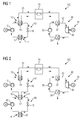
- FIG. 1 shows a circuit diagram of a first possible embodiment of the thermal storage device 100 according to the invention, which in addition to a first heat pump 10, a heat storage 20 and a circuit 30 for performing a thermal cycle process, by means of which the reconverting of the thermal energy stored in the heat storage 20 is made possible.
- the first heat pump 10 is adapted to thermal energy at a temperature level between 40 and 120 ° C, in particular between 50 ° C and 90 ° C, receive on a first input side 11 and on a first output side 12 thermal energy at a raised temperature level between 100 ° C and 300 ° C, in particular between 120 ° C and 200 ° C, deliver.
- the first input side 11 corresponds in this case to a first heat exchanger 17 and the first output side 12 to a further heat exchanger 18.
- the thermal energy on the first output side 12 is at least partially transferred to a heat storage medium 21, which supplies the thermal energy absorbed in this way to the heat accumulator 20 and deposits it in the meantime.
- the heat storage medium 21 is located in a suitable fluid line system, which is thermally connected to the first output side 12, and can also interact thermally with the heat accumulator 20 at the same time.
- the heat storage medium can be designed both in terms of a heat storage medium 20 located in the heat storage, as well as a medium which mediates the heat transfer between the first output side 12 of the first heat pump 10 and the heat storage 20.
- the working fluid of the heat pump 10 transfers the heat directly to the heat storage 20.
- this thermal energy can again be withdrawn in order to supply it to the circuit 30.
- the thermal energy is transferred to the heat transfer medium 32 located in the circuit 30 by means of a heat exchanger 37 become.
- the circuit is designed to carry out a thermal cycle and the heat transfer medium 32 is capable of energizing the power generating device 31 connected to the circuit 30.
- the power generating device 31 is presently designed as an expander 36 which interacts mechanically with a power generator (G). As a source of cold is used in this thermal cycle another heat exchanger 38, which is also connected in the circuit 30. For fluid conveyance or for assisted fluid transport, the circuit 30 provides a pump 35, which acts on the heat transfer medium 32 located therein with a flow.
- the thermal storage device 100 can consequently absorb heat at the first input side 11 of the first heat pump 10 and decouple it at an elevated temperature level via the first output side 12 of the first heat pump 10.
- the heat pump 10 is provided both thermal heat at the first input side 11, as well as electrical energy, which in the present case for the operation of a motor (M) is provided, which drives a compressor 15.
- the compressor 15 is adapted to provide thermal heat at a raised temperature level between 100 ° C and 300 ° C, especially between 120 ° C and 200 ° C.
- the first heat pump 10 is furthermore designed as a closed circuit, in which a circulating medium not provided with reference numerals is circulated.
- an adjusting means 16 is connected as a pressure change unit in the first heat pump 10.
- a slightly wet, dry and / or isentropic working fluid heat pump medium
- fluoroketones eg CF 3 CF 2 CF (CFC) 2
- refrigerant chlorinated and / or fluorinated hydrocarbons (eg R245ca)
- hydrocarbons eg butane, pentane
- other organic solvents eg toluene
- the first heat pump 10 can thus increase the total heat output by it and increase it to a temperature level suitable for intermediate storage in the heat accumulator 20 by simultaneous absorption of electrical energy and thermal energy, which is typically provided in the form of waste heat energy.
- FIG. 2 shows a further embodiment of the thermal storage device 100 according to the invention in a schematic circuit diagram.
- the in. Differs FIG. 2 shown embodiment of the in FIG. 1 embodiment shown only to the effect that the first heat pump 10, a second heat pump 40 is connected upstream thermally, the second heat pump 40 is adapted to receive thermal energy at a temperature level between 0 ° C and 60 ° C at a second input side 41 and at a second Output side 42 thermal energy at a raised temperature level between 40 ° C and 120 ° C, especially between 50 ° C and 90 ° C.
- the second input side of the second heat pump 40 is presently designed as a heat exchanger 47.
- the second output side of the second heat pump 40 in this case corresponds to the heat exchanger 17, which also represents the first input side 11 of the first heat pump 10.
- First heat pump 10 and second heat pump 40 are therefore thermally coupled to each other via a heat exchanger 17.
- the second heat pump 40 provides a compressor 45, which in turn can be operated electrically via a motor (M).
- the second heat pump 40 may also have a working as a pressure change unit actuating means 46 which is adapted to the in the second heat pump 40 circulated fluid to pressurize with a flow.
- FIG. 3 shows a further advantageous embodiment of the thermal storage device 100 according to the invention, wherein according to the embodiment, the first heat pump 10 is connected to the circuit 30 thermally. Furthermore, the heat pump 10 and the circuit 30 have common components that are suitable for the process engineering coupling of both processes.
- the first heat pump 10 is designed as a compressor 15 driven by a motor (M).
- the motor (M) can also be operated as a generator (G) in another operating mode.
- the motor (M) can also be used as a power generating device 31.
- the compressor 15 is mechanically connected to an expander 36 via a common shaft, which may possibly also have a coupling, so that, depending on the operating mode, the motor (M) or generator (G) in each case with the compressor 15 and the expander 36th interacts mechanically.
- the present embodiment has a compressor expander unit 50 which is simultaneously encompassed by both the first heat pump 10 and the circuit 30.
- thermal energy can be raised to a higher temperature level.
- the temperature level is suitable for thermal intermediate storage in the heat accumulator 20.
- the thermal energy provided by the operation of the compressor 15 is transferred to the heat storage medium 21, which is also the heat pump medium circulated in the first heat pump 10 at the same time.
- the heat storage medium 21 interacts with a working as a pressure change unit actuating means 16 and flows back to the first input side 11 of the heat pump circuit.
- the first input side 11 is designed as a heat exchanger 60, which can be used both as a heat source as well as a source of cold depending on the operating condition.
- thermal energy can now be taken from the heat accumulator 20, which in the present case is guided via the expander 36 and used to operate the power generating device 31 as a generator (G).
- the heat transfer medium 32 can be supplied to the heat exchanger 60.
- the heat exchanger 60 is connected to another line that allows this return, this line be provided with a pump 35 for acting on the heat transfer medium 32 with a flow can.
- the actuating means 16 and pump 35 included in the embodiment can be replaced by a single unit, which can be operated in respectively opposite directions.
- the two cable guides shown are formed as a single cable routing.
- the compressor expander unit 50 has only one working machine which can fulfill both the function of the compressor 15 and that of the expander 36. In this case, it may again be necessary for the work machine to be in the same position Currents can be used accordingly.
- the two cable guides shown are formed as a single wiring.
- FIG. 4 schematically shows the thermodynamic state changes of the working fluid in operation of a thermal storage device 100, as shown in FIG. 3 is shown in a TS diagram.
- the individual designated states in the diagram shown here correspond to those in FIG. 3 81, 82, 83, 84 and 91, 92, 93, and 94, which indicate locations at which the working fluid has a specific state.
- the phase boundary line for a nearly isentropic working fluid (right branch of the phase boundary line) is shown as a thick line. This phase boundary line encloses down the area of a two-phase mixture.
- phase transition is shown as a thickened line on the isothermal temperature level 86, an idealized phase transition, as it can be done in a latent heat storage, for example, wherein the melting and solidification of the storage material is carried out at a temperature level. Since in real conditions the solidification temperature differs slightly from the melting temperature, the phase transition is shown as a thickened line to better illustrate this slight temperature difference.
- the operating process is shown here for a subcritical operation, i. the maximum working fluid temperature is always below its critical temperature.
- the storage of heat in heat storage 20 takes place at the isothermal temperature level 86 in the range between 100 ° C and 300 ° C, in particular between 120 ° C and 200 ° C.
- Particularly advantageous is an isothermal storage, as is possible by latent heat storage or thermo-chemical heat storage, ie it is a phase transition or a physical or chemical reaction to store the heat used.
- condensed working fluid is present at point 91 in front of the heat exchanger 60.
- the temperature level of the heat absorption 87 is between 40 ° C and 120 ° C, in particular between 50 ° C and 90 ° C.
- the working fluid After heat absorption, the working fluid is present in the TS diagram at point 92, ie evaporation or overheating has taken place. After the compressor 15, the working fluid is at point 93 at a higher temperature. The heat is transferred to the heat accumulator 20 until the point 94 is reached. Then there is a further heat release or pressure change until the initial state 91 is reached again.
- the thermal circuit for reconversion is also in Fig. 4 shown.
- working fluid is compressed in the liquid phase from point 81 to point 82. Then there is a heat absorption from the heat storage 20 until the point 83 is reached.
- work is performed and discharged through the power generating device 31 to the outside. After expansion, the working fluid is present at point 84 and reaches the initial state 81 again due to the removal of heat with condensation.
- FIG. 5 shows a further particularly preferred embodiment of the thermal storage device 100 according to the invention, wherein the heat pump 10 and the heat accumulator 20 are interconnected in a closed circuit.
- the heat pump 10 is designed as a chemical heat pump, wherein the heat accumulator 20 is designed as a thermo-chemical heat storage.
- the system of first heat pump 10 and heat storage 20 allows by suitable adsorption and desorption processes, or chemical and physical reactions in the heat storage 20, the provision of thermal energy, which in turn can be provided to the circuit 30.
- a heat exchanger 17 is provided on the first input side 11 of the first heat pump 10.
- the first heat pump 10 comprises a turbomachine 19 (compressor), which moves the heat storage medium 21 guided in this circuit between the heat accumulator 20 and the first inlet side 11, that is to say it applies a flow.
- thermal heat can be absorbed in the heat storage by absorption or adsorption and corresponding desorption processes, or by chemical and physical reactions thermal energy (typically by desorption) or thermal energy are emitted (typically by absorption or adsorption).
- the heat released during operation of the first heat pump 10 can also be temporarily stored in the heat storage.
- FIG. 6 shows an idealized calculation of the current-to-current efficiency (PtP-E) as a function of the temperature level of the heat provided to the first heat pump 10, which in the present case is provided as waste heat.
- This temperature level (WHT) relates to typical temperature levels of waste heat in a power plant process.
- the curve labeled C is based on relatively conservative assumptions about the efficiencies of individual components of the thermal storage device 100.
- ORC Organic Rankine Cycle
- the grade of the heat pump (ie, the efficiency to Carnot efficiency ratio) and the cycle 30 were assumed to be 50%.
- the heat storage temperature in the heat storage 20 was assumed to 140 ° C, heat losses are 10%, the heat storage capacity is 25 K, the condensation temperature of the ORC 35 ° C.
- the Efficiency at a temperature level of more than 90 ° C already about 40%.
Priority Applications (2)
| Application Number | Priority Date | Filing Date | Title |
|---|---|---|---|
| EP13152372.2A EP2759679A1 (fr) | 2013-01-23 | 2013-01-23 | Dispositif de stockage thermique destiné à l'utilisation de chaleur à basse température |
| PCT/EP2014/050643 WO2014114531A1 (fr) | 2013-01-23 | 2014-01-15 | Dispositif d'accumulation thermique permettant d'utiliser de la chaleur basse température |
Applications Claiming Priority (1)
| Application Number | Priority Date | Filing Date | Title |
|---|---|---|---|
| EP13152372.2A EP2759679A1 (fr) | 2013-01-23 | 2013-01-23 | Dispositif de stockage thermique destiné à l'utilisation de chaleur à basse température |
Publications (1)
| Publication Number | Publication Date |
|---|---|
| EP2759679A1 true EP2759679A1 (fr) | 2014-07-30 |
Family
ID=47681682
Family Applications (1)
| Application Number | Title | Priority Date | Filing Date |
|---|---|---|---|
| EP13152372.2A Withdrawn EP2759679A1 (fr) | 2013-01-23 | 2013-01-23 | Dispositif de stockage thermique destiné à l'utilisation de chaleur à basse température |
Country Status (2)
| Country | Link |
|---|---|
| EP (1) | EP2759679A1 (fr) |
| WO (1) | WO2014114531A1 (fr) |
Cited By (6)
| Publication number | Priority date | Publication date | Assignee | Title |
|---|---|---|---|---|
| CN106762487A (zh) * | 2016-12-06 | 2017-05-31 | 中国科学技术大学 | 具有两级蓄热水罐的直膨式太阳能热电联供系统 |
| WO2017142496A1 (fr) * | 2016-02-18 | 2017-08-24 | Vural Erdal | Système de refroidissement et de production d'électricité |
| WO2018178154A1 (fr) * | 2017-03-28 | 2018-10-04 | Hsl Energy Holding Aps | Centrale d'accumulation d'énergie thermique |
| WO2020193569A1 (fr) * | 2019-03-25 | 2020-10-01 | Wim De Graeve | Procédé de récupération de chaleur perdue |
| WO2022233582A3 (fr) * | 2021-05-07 | 2023-02-23 | Deutsches Zentrum für Luft- und Raumfahrt e.V. | Procédé pour faire fonctionner une installation de stockage, installation de stockage, programme de commande et support lisible par ordinateur |
| DE102022125604A1 (de) | 2022-10-05 | 2024-04-11 | Man Energy Solutions Se | System und Verfahren zur Energiewandlung und Energiespeicherung |
Families Citing this family (25)
| Publication number | Priority date | Publication date | Assignee | Title |
|---|---|---|---|---|
| US10094219B2 (en) | 2010-03-04 | 2018-10-09 | X Development Llc | Adiabatic salt energy storage |
| WO2014052927A1 (fr) | 2012-09-27 | 2014-04-03 | Gigawatt Day Storage Systems, Inc. | Systèmes et procédés de récupération et de stockage d'énergie |
| BR112015021396A2 (pt) | 2013-03-04 | 2017-08-22 | Echogen Power Systems Llc | Sistemas de motor de calor com circuitos de dióxido de carbono supercrítico de alto potência útil |
| US20160123206A1 (en) * | 2014-11-03 | 2016-05-05 | The Boeing Company | Waste heat reclamation system, method for reclamation of waste heat, and system and method for using waste heat |
| DE102015203235A1 (de) * | 2015-02-24 | 2016-08-25 | Vaillant Gmbh | Adsorptions-Wärmepumpe |
| CN105179033B (zh) * | 2015-08-12 | 2017-05-31 | 中国科学院工程热物理研究所 | 一种利用低温冷能存储电能的系统及其运行方法 |
| CN105114138B (zh) * | 2015-08-12 | 2016-08-31 | 中国科学院工程热物理研究所 | 一种低温储能发电系统及其运行方法 |
| US10233787B2 (en) | 2016-12-28 | 2019-03-19 | Malta Inc. | Storage of excess heat in cold side of heat engine |
| US10458284B2 (en) | 2016-12-28 | 2019-10-29 | Malta Inc. | Variable pressure inventory control of closed cycle system with a high pressure tank and an intermediate pressure tank |
| US11053847B2 (en) | 2016-12-28 | 2021-07-06 | Malta Inc. | Baffled thermoclines in thermodynamic cycle systems |
| US10233833B2 (en) | 2016-12-28 | 2019-03-19 | Malta Inc. | Pump control of closed cycle power generation system |
| US10221775B2 (en) | 2016-12-29 | 2019-03-05 | Malta Inc. | Use of external air for closed cycle inventory control |
| US10801404B2 (en) | 2016-12-30 | 2020-10-13 | Malta Inc. | Variable pressure turbine |
| US10436109B2 (en) | 2016-12-31 | 2019-10-08 | Malta Inc. | Modular thermal storage |
| CA3088184A1 (fr) | 2018-01-11 | 2019-07-18 | Lancium Llc | Procede et systeme d'alimentation dynamique d'un centre de donnees flexible au moyen de sources d'energie non utilisees |
| US10883388B2 (en) | 2018-06-27 | 2021-01-05 | Echogen Power Systems Llc | Systems and methods for generating electricity via a pumped thermal energy storage system |
| CN116557091A (zh) | 2019-11-16 | 2023-08-08 | 马耳他股份有限公司 | 具有热存储介质再平衡的双动力系统泵送热能存储 |
| US11435120B2 (en) | 2020-05-05 | 2022-09-06 | Echogen Power Systems (Delaware), Inc. | Split expansion heat pump cycle |
| US11480067B2 (en) | 2020-08-12 | 2022-10-25 | Malta Inc. | Pumped heat energy storage system with generation cycle thermal integration |
| US11286804B2 (en) | 2020-08-12 | 2022-03-29 | Malta Inc. | Pumped heat energy storage system with charge cycle thermal integration |
| US11486305B2 (en) | 2020-08-12 | 2022-11-01 | Malta Inc. | Pumped heat energy storage system with load following |
| US11396826B2 (en) | 2020-08-12 | 2022-07-26 | Malta Inc. | Pumped heat energy storage system with electric heating integration |
| US11454167B1 (en) | 2020-08-12 | 2022-09-27 | Malta Inc. | Pumped heat energy storage system with hot-side thermal integration |
| KR20230117402A (ko) | 2020-12-09 | 2023-08-08 | 수퍼크리티컬 스토리지 컴퍼니, 인크. | 3 저장조 전기 열 에너지 저장 시스템 |
| DE102022105052A1 (de) | 2022-03-03 | 2023-09-07 | Man Energy Solutions Se | System zur Wasserdampf- und/oder Wärmeerzeugung und Verfahren zum Betreiben desselben |
Citations (6)
| Publication number | Priority date | Publication date | Assignee | Title |
|---|---|---|---|---|
| US4682476A (en) * | 1983-07-01 | 1987-07-28 | Societe Nationale Elf Aquitaine | Three-phase heat pump |
| EP1577548A1 (fr) * | 2004-03-16 | 2005-09-21 | Abb Research Ltd. | Dispositif et procédé de stockage d'énergie thermale et de génération d'électricité |
| EP2241737A1 (fr) * | 2009-04-14 | 2010-10-20 | ABB Research Ltd. | Système de stockage d'énergie thermoélectrique doté de deux thermes et procédé de stockage d'énergie thermoélectrique |
| US20110100611A1 (en) * | 2008-07-16 | 2011-05-05 | Abb Research Ltd | Thermoelectric energy storage system and method for storing thermoelectric energy |
| DE102010019964A1 (de) * | 2010-05-08 | 2011-11-10 | Ralf Bischoff | Verfahren zur Wandlung und Speicherung thermischer Energien |
| EP2390473A1 (fr) * | 2010-05-28 | 2011-11-30 | ABB Research Ltd. | Système de stockage d'énergie thermoélectrique et procédé de stockage d'énergie thermoélectrique |
Family Cites Families (1)
| Publication number | Priority date | Publication date | Assignee | Title |
|---|---|---|---|---|
| US6523347B1 (en) * | 2001-03-13 | 2003-02-25 | Alexei Jirnov | Thermodynamic power system using binary working fluid |
-
2013
- 2013-01-23 EP EP13152372.2A patent/EP2759679A1/fr not_active Withdrawn
-
2014
- 2014-01-15 WO PCT/EP2014/050643 patent/WO2014114531A1/fr active Application Filing
Patent Citations (6)
| Publication number | Priority date | Publication date | Assignee | Title |
|---|---|---|---|---|
| US4682476A (en) * | 1983-07-01 | 1987-07-28 | Societe Nationale Elf Aquitaine | Three-phase heat pump |
| EP1577548A1 (fr) * | 2004-03-16 | 2005-09-21 | Abb Research Ltd. | Dispositif et procédé de stockage d'énergie thermale et de génération d'électricité |
| US20110100611A1 (en) * | 2008-07-16 | 2011-05-05 | Abb Research Ltd | Thermoelectric energy storage system and method for storing thermoelectric energy |
| EP2241737A1 (fr) * | 2009-04-14 | 2010-10-20 | ABB Research Ltd. | Système de stockage d'énergie thermoélectrique doté de deux thermes et procédé de stockage d'énergie thermoélectrique |
| DE102010019964A1 (de) * | 2010-05-08 | 2011-11-10 | Ralf Bischoff | Verfahren zur Wandlung und Speicherung thermischer Energien |
| EP2390473A1 (fr) * | 2010-05-28 | 2011-11-30 | ABB Research Ltd. | Système de stockage d'énergie thermoélectrique et procédé de stockage d'énergie thermoélectrique |
Non-Patent Citations (2)
| Title |
|---|
| COT-GORES, J.; CASTELL, A.; CABEZA, L.F.: "Thermochemical Energy Storage and Conversion: A State of the Art Review of the Experimental Research under Practical Conditions", RENEWABLE AND SUSTAINABLE ENERGY REVIEWS, vol. 16, 2012, pages 5207 - 5224, XP028408351, DOI: doi:10.1016/j.rser.2012.04.007 |
| WONGSUWAN, W.; KUMAR, S.; NEVEU, P.; MEUNIER, F.: "A Review of Chemical Heat Pump Technology and Applications", APPLIED THERMAL ENGINEERING, vol. 21, 2001, pages 1489 - 1519 |
Cited By (6)
| Publication number | Priority date | Publication date | Assignee | Title |
|---|---|---|---|---|
| WO2017142496A1 (fr) * | 2016-02-18 | 2017-08-24 | Vural Erdal | Système de refroidissement et de production d'électricité |
| CN106762487A (zh) * | 2016-12-06 | 2017-05-31 | 中国科学技术大学 | 具有两级蓄热水罐的直膨式太阳能热电联供系统 |
| WO2018178154A1 (fr) * | 2017-03-28 | 2018-10-04 | Hsl Energy Holding Aps | Centrale d'accumulation d'énergie thermique |
| WO2020193569A1 (fr) * | 2019-03-25 | 2020-10-01 | Wim De Graeve | Procédé de récupération de chaleur perdue |
| WO2022233582A3 (fr) * | 2021-05-07 | 2023-02-23 | Deutsches Zentrum für Luft- und Raumfahrt e.V. | Procédé pour faire fonctionner une installation de stockage, installation de stockage, programme de commande et support lisible par ordinateur |
| DE102022125604A1 (de) | 2022-10-05 | 2024-04-11 | Man Energy Solutions Se | System und Verfahren zur Energiewandlung und Energiespeicherung |
Also Published As
| Publication number | Publication date |
|---|---|
| WO2014114531A1 (fr) | 2014-07-31 |
Similar Documents
| Publication | Publication Date | Title |
|---|---|---|
| EP2759679A1 (fr) | Dispositif de stockage thermique destiné à l'utilisation de chaleur à basse température | |
| EP2748434B1 (fr) | Installation de stockage d'énergie thermique | |
| EP2900943B1 (fr) | Centrale de cogénération et procédé de fonctionnement d'une centrale de cogénération | |
| EP2823156B1 (fr) | Installation pour le stockage et le dépôt d'énergie thermique | |
| EP2067942B1 (fr) | Procédé de transformation et de stockage d'énergie régénérative | |
| EP2450549A2 (fr) | Centrale électrique de stockage de chaleur par compression et procedé de stockage d'énergie pour stocker temporairement l'énergie sous forme d'énergie de pression dans un milieu compressible en forme d'énergie thermique | |
| EP2574739A1 (fr) | Installation de stockage d'énergie thermique et son procédé de fonctionnement | |
| EP2994699B1 (fr) | Méthode et agencement pour fournir de la chaleur à un réseau de chauffage à distance | |
| WO2014026863A2 (fr) | Procédé de charge et de décharge d'un accumulateur de chaleur et installation permettant l'accumulation et la distribution d'énergie thermique, adaptée au procédé de charge et de décharge d'un accumulateur de chaleur | |
| WO2015131940A1 (fr) | Installation de stockage d'énergie à haute température et procédé de fonctionnement associé | |
| EP3006682B1 (fr) | Dispositif et procédé de fonctionnement d'une station de transmission thermique | |
| EP2825737A1 (fr) | Installation d'accumulation et de distribution d'énergie thermique au moyen d'un accumulateur de chaleur et d'un accumulateur de froid et procédé de fonctionnement de ladite installation | |
| EP3080407B1 (fr) | Accumulation d'énergie au moyen d'un accumulateur de chaleur et d'un thermocompresseur de vapeur | |
| EP2415976A1 (fr) | Moteur thermique destiné à transformer de l'énergie thermique en énergie mécanique, laquelle est utilisée pour la production d'électricité, ainsi que procédé de fonctionnement d'un tel moteur thermique | |
| DE102012217142A1 (de) | Verfahren zum Laden und Entladen eines Speichermediums in einem Wärmespeicher und Anlage zur Durchführung dieses Verfahrens | |
| EP2902604A1 (fr) | Procédé et dispositif de stockage d'énergie | |
| WO2022101348A1 (fr) | Accumulateur d'énergie thermique pour le stockage d'énergie électrique | |
| WO2018029371A1 (fr) | Échangeur de chaleur destiné à être utilisé dans une partie chaude d'une centrale de stockage d'énergie par air liquide, partie chaude et procédé permettant de faire fonctionner ledit échangeur de chaleur dans ladite partie chaude | |
| WO2012152602A1 (fr) | Circuit de conduite et procédé permettant de faire fonctionner un circuit de conduite destiné à récupérer la chaleur dissipée d'un moteur à combustion interne | |
| DE102011101665A1 (de) | Wärmeeinheit zum Erzeugen elektrischer Energie | |
| EP2951407A2 (fr) | Procédé permettant de faire fonctionner une centrale basse température et centrale basse température | |
| DE202010008126U1 (de) | Wärmekraftmaschine zur Umwandlung von Wärmeenergie in mechanische Energie, die zur Erzeugung von Strom benutzt wird | |
| WO2023011997A1 (fr) | Moteur thermique | |
| DE202023103656U1 (de) | Anlage zur Energie- und/oder Stoffversorgung mindestens eines Verbrauchers | |
| WO2014154402A1 (fr) | Système de gaz naturel avec accumulateur de chaleur |
Legal Events
| Date | Code | Title | Description |
|---|---|---|---|
| PUAI | Public reference made under article 153(3) epc to a published international application that has entered the european phase |
Free format text: ORIGINAL CODE: 0009012 |
|
| 17P | Request for examination filed |
Effective date: 20130123 |
|
| AK | Designated contracting states |
Kind code of ref document: A1 Designated state(s): AL AT BE BG CH CY CZ DE DK EE ES FI FR GB GR HR HU IE IS IT LI LT LU LV MC MK MT NL NO PL PT RO RS SE SI SK SM TR |
|
| AX | Request for extension of the european patent |
Extension state: BA ME |
|
| STAA | Information on the status of an ep patent application or granted ep patent |
Free format text: STATUS: THE APPLICATION IS DEEMED TO BE WITHDRAWN |
|
| 18D | Application deemed to be withdrawn |
Effective date: 20150131 |