EP2759640A1 - Befestigungseinrichtung - Google Patents
Befestigungseinrichtung Download PDFInfo
- Publication number
- EP2759640A1 EP2759640A1 EP20140151327 EP14151327A EP2759640A1 EP 2759640 A1 EP2759640 A1 EP 2759640A1 EP 20140151327 EP20140151327 EP 20140151327 EP 14151327 A EP14151327 A EP 14151327A EP 2759640 A1 EP2759640 A1 EP 2759640A1
- Authority
- EP
- European Patent Office
- Prior art keywords
- fastening device
- film
- cover
- chamber
- wall
- Prior art date
- Legal status (The legal status is an assumption and is not a legal conclusion. Google has not performed a legal analysis and makes no representation as to the accuracy of the status listed.)
- Granted
Links
- 230000001747 exhibiting effect Effects 0.000 claims abstract description 5
- 239000013013 elastic material Substances 0.000 claims description 9
- 239000004033 plastic Substances 0.000 claims description 9
- 239000000463 material Substances 0.000 claims description 8
- 239000000853 adhesive Substances 0.000 claims description 6
- 230000001070 adhesive effect Effects 0.000 claims description 6
- 239000007787 solid Substances 0.000 claims description 6
- 238000007789 sealing Methods 0.000 claims description 5
- 230000005641 tunneling Effects 0.000 claims description 4
- 239000006260 foam Substances 0.000 claims description 3
- 238000002347 injection Methods 0.000 claims description 3
- 239000007924 injection Substances 0.000 claims description 3
- 239000002985 plastic film Substances 0.000 claims description 3
- 229920006255 plastic film Polymers 0.000 claims description 3
- 229920001296 polysiloxane Polymers 0.000 claims description 3
- XLYOFNOQVPJJNP-UHFFFAOYSA-N water Substances O XLYOFNOQVPJJNP-UHFFFAOYSA-N 0.000 claims description 2
- 239000011888 foil Substances 0.000 abstract description 2
- 238000011161 development Methods 0.000 description 8
- 206010040844 Skin exfoliation Diseases 0.000 description 6
- 239000004746 geotextile Substances 0.000 description 4
- 239000011435 rock Substances 0.000 description 4
- 238000004519 manufacturing process Methods 0.000 description 3
- 238000000034 method Methods 0.000 description 3
- 238000010008 shearing Methods 0.000 description 3
- 239000011378 shotcrete Substances 0.000 description 3
- 238000006243 chemical reaction Methods 0.000 description 2
- 238000003825 pressing Methods 0.000 description 2
- 238000003466 welding Methods 0.000 description 2
- 239000004952 Polyamide Substances 0.000 description 1
- 239000004698 Polyethylene Substances 0.000 description 1
- 239000004676 acrylonitrile butadiene styrene Substances 0.000 description 1
- 238000004026 adhesive bonding Methods 0.000 description 1
- 239000004567 concrete Substances 0.000 description 1
- 238000013461 design Methods 0.000 description 1
- 239000004744 fabric Substances 0.000 description 1
- 239000003292 glue Substances 0.000 description 1
- 230000001771 impaired effect Effects 0.000 description 1
- 238000003780 insertion Methods 0.000 description 1
- 230000037431 insertion Effects 0.000 description 1
- 239000002184 metal Substances 0.000 description 1
- 239000007769 metal material Substances 0.000 description 1
- 238000004806 packaging method and process Methods 0.000 description 1
- 229920002647 polyamide Polymers 0.000 description 1
- 239000004417 polycarbonate Substances 0.000 description 1
- 229920000515 polycarbonate Polymers 0.000 description 1
- 238000012545 processing Methods 0.000 description 1
- 230000001681 protective effect Effects 0.000 description 1
- 238000005096 rolling process Methods 0.000 description 1
- 125000006850 spacer group Chemical group 0.000 description 1
- 238000012549 training Methods 0.000 description 1
Images



Classifications
-
- E—FIXED CONSTRUCTIONS
- E02—HYDRAULIC ENGINEERING; FOUNDATIONS; SOIL SHIFTING
- E02D—FOUNDATIONS; EXCAVATIONS; EMBANKMENTS; UNDERGROUND OR UNDERWATER STRUCTURES
- E02D17/00—Excavations; Bordering of excavations; Making embankments
- E02D17/20—Securing of slopes or inclines
-
- E—FIXED CONSTRUCTIONS
- E02—HYDRAULIC ENGINEERING; FOUNDATIONS; SOIL SHIFTING
- E02D—FOUNDATIONS; EXCAVATIONS; EMBANKMENTS; UNDERGROUND OR UNDERWATER STRUCTURES
- E02D31/00—Protective arrangements for foundations or foundation structures; Ground foundation measures for protecting the soil or the subsoil water, e.g. preventing or counteracting oil pollution
- E02D31/02—Protective arrangements for foundations or foundation structures; Ground foundation measures for protecting the soil or the subsoil water, e.g. preventing or counteracting oil pollution against ground humidity or ground water
- E02D31/025—Draining membranes, sheets or fabric specially adapted therefor, e.g. with dimples
Definitions
- the invention relates to a fastening device for fastening of a film for sealing purposes on a solid wall in engineering, civil engineering, water, and tunneling using at least one directly or indirectly fixed to the fixed conversion support element.
- Such a fastening device is known from EP 1 057 940 A1 known.
- a geotextile layer is attached by means of a nail, for example, to a solid wall coated with shotcrete.
- support elements in the form of flat plastic plates are attached to the geotextile at regular intervals, which are held by nails driven into the shotcrete layer.
- a geomembrane is glued in the form of a film, for example.
- Another embodiment provides for Velcro straps nailed directly to the spiked layer and press on this Velcro strips provided with a geotextile film. The problem is that the Velcro straps are usually not sufficiently stiff and therefore the attachment of the provided with the geotextile film on the fabric straps is difficult.
- Another fastening arrangement provides that the nonwoven layer is first attached to the wall with special carrier elements in the form of holding cleats. In a second operation will be then the normal Rondelle to which the film is attached by gluing or welding in a third operation attached.
- a common feature of all these fastening arrangements or the corresponding fastening method is that several sequentially proceeding operations must be performed.
- the rigid film does not come into contact with the rondelles or the Velcro strips in a flat manner and therefore there is the risk of detachment of the film by peeling.
- the invention has for its object to provide a mounting arrangement that is improved over the prior art in the form that a peeling of the film is avoided by the support member.
- the carrier element is an elastic and a chamber exhibiting cushion to which the film is attached directly or indirectly.
- An elastic region formed by the cushion can be adapted to the contour of the film when the film is pressed on, thus producing a flat contact with the film. It is the case here that both the wall can have unevenness or else the film does not completely assume the contour of the wall due to its stiffness. Both circumstances lead without the elastic cushion to the fact that the film would not lie flat against the support element and therefore it could come to a peeling. This is avoided by the fact that the elastic cushion of the contour of the film, safely avoided, since the applied surface pressure is the same everywhere.
- the cushion can be realized in any configuration.
- the cushion has a base element and a cover connected to the base element and enclosing the chamber.
- the base element and the covers can be made of the same elastic material, in particular a plastic material to be made.
- the cushion thus formed is either attached directly to the fixed hike or interacts with one of the solid wall facing Rondelle together.
- the Rondelle can be fastened together with the cushion thus formed on the fixed wall.
- it can be provided that to arrange pillows between the solid wall and the Rondelle and fasten the Rondelle together with the cushion on the fixed wall.
- the base element is at least approximately stiff and the chamber of the cushion is embedded in the base element.
- the base member is preferably formed as a rondel.
- the elastic region of the pad is formed by the chamber, which is closed on the film side by a deformable, elastic cover.
- a deformable, elastic cover Such a trained fastening device can be produced easily.
- the base element may be made of any desired material and the cover may, for example, be glued or welded onto the base element. In this case, the connection between the base member and the cover only in edge regions, so that the cover can move more or less freely between the edge regions.
- the depth of the chamber is dimensioned so that compensating movements of the cover are possible without the compensating movement of the cover is obstructed by a bottom wall of the chamber.
- the chamber surrounds an at least approximately centrally arranged on the base element or the rondel mounting area for the base element or the rondel.
- the Fastening region is preferably circular and has a central opening through which a fastening means, such as a bolt, nail or screw can be performed.
- a bolt can for example be driven with a bolt setting device with the interposition of the pad according to the invention in the solid wall, such as rock or rock, and thus the cushion be permanently attached to the conversion.
- the cushion or the basic element of the pad is a manufactured as an injection molded part or deep-drawn plastic part. Both methods are suitable for the production of the pillow according to the invention or of the basic element of the pillow or the roundel including the chamber and the fastening area.
- the plastic material is for example ABS, PE, polyamide, or polycarbonate. Especially ABS is impact resistant and can be processed well beyond.
- a further embodiment of the invention provides that the cover is a film material, in particular a plastic film.
- This cover thus formed may optionally be made in one operation together with the base element or applied to this.
- the cover may for example have a thickness of 30 microns to 80 microns, in particular from 50 microns to 60 microns.
- the chamber is filled with air.
- This embodiment is particularly advantageous because in this embodiment, the base element can be easily manufactured in one operation together with the cover.
- the chamber is filled with an elastic material, such as foam, silicone or gel.
- This elastic material is used in particular as Spacer, which presses the cover away from the bottom wall of the base member and which is so resilient in the pressing of the film, that a flat connection of the film or a non-woven finish explained below with the cover.
- the cover is formed by the elastic material.
- the elastic material is silicone or gel, for example, and thus the cover can be easily represented by an upper layer of the material.
- a development of the invention provides that the bottom wall of the attachment region of the base element or of the corresponding part of the roundel has a thicker wall thickness than the bottom wall of the chamber.
- This configuration ensures that damage to the base element or its bottom wall is excluded in a fastening of the base element, for example by a bolt setting device even with unevenness on the wall.
- the wall thickness of the bottom wall of the attachment area may contribute 2-4 times the wall thickness of the bottom wall in the area of the chamber. Possible values for the wall thickness of the bottom wall are 1 mm for the area of the chamber and 2 mm for the area of the fastening area.
- an adhesive is applied to the film side facing the cover.
- the adhesive can be applied during production of the pad and protected by a release liner. When the film is attached, the release film is then removed.
- the adhesive can also be applied to the cover only after the attachment of the pad to the wall directly before the film is pressed on. In this case, the protective film is unnecessary.
- a film without a nonwoven layer is preferably used, which is glued directly to the cover of the pad.
- a hook and loop body is arranged and fastened on the side of the pad facing the film.
- the film is provided with a nonwoven layer, with which the thus prepared film is attached to the surface of the Velcro body.
- the hooks of the hook and loop body penetrate into the fleece layer and ensure a secure attachment of the film to the roundel.
- the height of the hook is adapted to the thickness of the nonwoven layer.
- the hook and loop body is fastened with a fastening device on the film and / or the base element and or the rondel in a further embodiment.
- This fastening device can be, for example, a plastic rivet or a metal rivet.
- a Velcro backing is arranged between the side of the cover facing the film and the hook and loop body.
- the Velcro body is preferably glued.
- the Velcro backing is so elastic that it follows the contour of the pad, especially in the attachment area.
- This embodiment ensures that the hook and loop body is loaded predominantly only by a shearing load, which is caused by the film or the nonwoven layer interacting with the hook and loop body.
- the attached film can hang as required without the attachment is impaired.
- the efficiency of the attachment of the film to the Velcro body or in the case of sticking to the cover of the pad so well because when a rolling of the film on the entire surface of the same surface pressure prevails.
- the cushion or the Rondelle is rectangular. This training is preferably used in connection with an attachment of the film by means of the hook and loop body, since then a waste-free processing of the As a band provided Velcro is possible by a band with the width of the pad or the Rondelle is selected and a lengthening of the Velcro body is carried out according to the length of the Rondelle.
- FIG. 1 shows a fastening device with a carrier element, wherein the fastening device is used in particular in tunneling for fixing a film 2 for sealing purposes.
- the support member is formed as an elastic and a chamber 8 exhibiting cushion 1, to which on the film 2 side facing a hook and loop body 15 connects.
- the cushion 1 has a base wall 17 facing a fixed wall 11, for example, of a tunnel, and a cover 9, which is connected to the base element 17 and encloses the chamber 8, which faces the film 2.
- the base member 17 and the cover 9 are made with the inclusion of the chamber 8 of a plastic film material, which is used for example in the packaging industry.
- the base member 17 is welded to the cover 9 under a defined inclusion of air.
- the fastening device has a fastening region 3, which is separated from the chamber 8.
- the chamber 8 can also be separated, in particular by the attachment region 3, in several parts with separate parts chambers.
- a fastening means 12 such as a nail, pin, bolt, dowel or screw, optionally driven with the interim disposal of a disc 18 in the wall 11 or in a bore in the wall 11.
- On the cover 9 is shown in the illustration on the left side of the FIG.
- the Velcro 15 can also, as on the right side of FIG. 1 is shown, extend into the mounting portion 3 and are fastened together with the pad 1 with the fastener 12 directly on the wall 11.
- the Velcro body 15, at least in this attachment variant be glued to the cover 9 in places.
- fastening means coated with a nonwoven layer 16 film 2 is pressed and fixed.
- the fastening device is similar to an elastic region, which is formed in particular by the pad 1 and the chamber 8, unevenness of the wall 11, which may be, for example, rock or shotcrete, from.
- a two-dimensional pressing of the provided with a nonwoven layer 16 film 2 on the Velcro body 15 to a fastening which is designed in particular only to a shearing, but not on a peeling load, allows.
- FIG. 2 shows a similar fastening device as FIG. 1
- a Velcro carrier 20 between the cover 9 and the film 2 and the nonwoven finishing 16 is arranged.
- the Velcro backing 20 is made of a plastic or a metal material and as far as elastic that he gives in particular in the mounting portion 3 of the given by the pad 1 and the fastening means 12 with the insertion of the disc 18 contour.
- On the Velcro backing 20 of the Velcro 15 is glued.
- This embodiment using the hook and loop fastener 20 contributes to increasing the proportion of shearing stress on the hook and loop body 15 and reducing the proportion of peeling load. As a result, the holding force exerted on the nonwoven layer 16 or on the film 2 is further increased. Similar to the illustration according to FIG. 1 For example, the hook and loop body 15 can be guided into the fastening area 3 and additionally held by the fastening means 12.
- FIG. 3 shows a Rondelle 21, in particular in tunneling for fixing a film 2 ( FIGS. 5, 6 ) is used for sealing purposes.
- the rondel 21 is rectangular and has, for example, an edge length of approximately 100 mm.
- the edges 5 of the rondel 21 are twice to form a Angled surface 13 angled ( FIG. 4 ) and have a height of, for example, approximately 7 mm.
- These outer edges 5 define a chamber 8, which will be explained in more detail below.
- the Rondelle 1 has a mounting portion 3, which is circular or cup-shaped, and for example, has a diameter of approximately 30 mm.
- the height of the cup-shaped edge 6a with respect to a bottom wall 7a of the mounting portion 3 is approximately the same measure as the height of the edges 5.
- the rondel 21 subsequent to the inner pot-shaped edge 6a a mirror-image outer edge 6b, which with the other bottom wall 7b is connected in the region of the chamber 8.
- the edges 6a, 6b include a circumferential surface 13a corresponding to the surface 13.
- an opening 4 in the form of a hole is worked into the bottom wall 7a of the base element 17, through which a fastening means 12, in particular a bolt, pin, nail, dowel or a screw, can be inserted.
- the sectional view according to FIG. 4 shows the structure of a Rondelle 21 and in particular the subdivision into the inner mounting portion 3 and in the surrounding the inner mounting portion 3 chamber 8, which forms the pad 1.
- the wall thickness of the bottom wall 7a in the region of the attachment area 3 is for example 2 mm, while the wall thickness of the bottom wall 7b of the chamber 8 including the edges 6a, 6b and the edge 5 of the rondel 21 is for example 1 mm.
- a deformable and elastic cover 9 is fixed, for example, welded, in particular the chamber 8 completely and tightly covering and thus forms the elastic pad 1 .
- the interior 10 of the cover 9 covered by the chamber 8 is in this embodiment with air filled during the manufacturing process of the rondel 21, in particular during the welding of the cover 9 on the chamber 8 and the mounting portion 3 forming base member 17 of the rondel 21, a predetermined amount of air is introduced into the chamber 8 and thus enclosed.
- an elastic air cushion which allows, for example, in a one-sided pressure load on the cover 9, a dodging the same to the other side.
- the cover 9 can also cover the attachment region 3 and be pierced by the attachment means 12 during the attachment process of the rondel 21.
- the cover 9 has, for example, a thickness of 50 microns to 60 microns.
- Both the base element 17 of the rondel 21 and the cover 9 are preferably made of a plastic material, wherein the base element 17 is in particular an injection molded part or deep-drawn part.
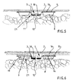
- FIG. 5 shows a fixed to a fixed wall 11, which is in particular rock or concrete in connection with a tunnel, attached rondelle 21.
- the rondel 21 is attached to the wall 11, for example with a fastening means 12 in the form of a nail with the interposition of a disc 18, wherein the Nail and the attached disc 18 with a fastening device, such as a bolt setting device, is driven into the wall 11.
- a film 2 is glued directly to the interposition of an adhesive 14.
- the film 2 used for sealing purposes and made of PE for example, has a thickness of 4 mm and is accordingly stiff.
- the film 2 is continuously pressed by means of a machine having elastic rollers on the rondels 21, 21 alignment errors, caused for example by an uneven wall 11, compared to the rigid film 2 by the movable cover 9 are compensated by the inventive design of the rondels.
- This is always one flat connection between a Rondelle 21 and the film 2 made so that the risk of peeling the film 2 is turned off by a Rondelle 21.
- the film 2 consists of individual webs which are welded together tightly.
- a hook and loop body 15 for example glued to the adhesive 14.
- the hook and loop body 15 can also be fixed to the wall 11 together with the rondel 21 only by means of the fastening means 12.
- the film 2 is provided in this embodiment with a nonwoven layer 16, wherein the nonwoven layer 16 is pressed into the Velcro body 15 and thus secured.
- the chamber 8 of the pad 1 is filled with an elastic material 19, for example foam.
- FIG. 7 shows a section through a Rondelle 21 a, which is fixed by means of a fastening means 12 to a wall 11.
- the rondel 21a has two wings 22, on each of which a hook and loop body 15 is preferably glued. Each of the two Velcro 15 projects beyond the respective support surface 22. Beneath the areas of the Velcro body 15 projecting beyond the support surfaces 22, a pad 1 or a pad section of the pad 1 is inserted.
- the cushion 1, in particular in the wings 22 projecting areas of the Velcro 15 is an elastic system for the Velcro 15.
- the pad 1 can be fixed in this embodiment, together with the rondel 21 a by means of the fastening means 12 on the wall 11.
Landscapes
- Engineering & Computer Science (AREA)
- Mining & Mineral Resources (AREA)
- Life Sciences & Earth Sciences (AREA)
- General Life Sciences & Earth Sciences (AREA)
- Paleontology (AREA)
- Civil Engineering (AREA)
- General Engineering & Computer Science (AREA)
- Structural Engineering (AREA)
- Environmental & Geological Engineering (AREA)
- Hydrology & Water Resources (AREA)
- Connection Of Plates (AREA)
Abstract
Description
- Die Erfindung betrifft eine Befestigungsvorrichtung zur Befestigung von einer Folie zu Abdichtzwecken an einer festen Wandung im Ingenieur-, Tief-, Wasser-, und Tunnelbau unter Verwendung von zumindest einem an der festen Wandlung direkt oder indirekt befestigten Trägerelement.
- Eine solche Befestigungsvorrichtung ist aus der
EP 1 057 940 A1 bekannt. Bei dieser Befestigungsvorrichtung wird eine Geotextilschicht mittels eines Nagels beispielsweise an einer mit Spritzbeton beschichteten festen Wandung befestigt. Dazu sind an der Geotextilschicht in regelmäßigen Abständen Trägerelemente in Form von flachen Kunststofftellern befestigt, die durch in die Spritzbetonschicht eingetriebene Nägel gehalten werden. An diesen Kunststofftellern wird eine Dichtungsbahn in Form einer Folie beispielsweise festgeklebt. Eine andere Ausführungsform sieht vor, Klettbänder direkt an der Spitzbetonschicht festzunageln und an diesem Klettbändern die mit einer Geotextilschicht versehene Folie anzudrücken. Problematisch ist dabei, dass die Klettbänder normalerweise nicht genügend steif sind und daher die Befestigung der mit der Geotextilschicht versehenen Folie an den Textilbändern schwierig ist. - Eine andere Befestigungsanordnung sieht vor, dass die Vliesschicht zunächst mit speziellen Trägerelementen in Form von Halterondellen an der Wandung befestigt wird. In einem zweiten Arbeitsgang werden dann die normalen Rondelle, an denen die Folie durch Ankleben oder Anschweißen in einem dritten Arbeitsgang befestigt wird, angebracht. Gemeinsames Merkmal aller dieser Befestigungsanordnungen beziehungsweise der entsprechenden Befestigungsverfahren ist es, dass mehrere nacheinander ablaufende Arbeitsvorgänge durchgeführt werden müssen. Zudem wird beobachtet, dass beim Andrücken der Folie an die mit Kleber versehenen Rondelle oder an das Klettband die steife Folie nicht flächig mit den Rondellen oder den Klettbändern in Kontakt kommt und daher die Gefahr eines Loslösens der Folie durch Abschälen besteht.
- Der Erfindung liegt die Aufgabe zugrunde eine Befestigungsanordnung anzugeben, die gegenüber dem Stand der Technik in der Form verbessert ist, dass ein Abschälen der Folie von dem Trägerelement vermieden wird.
- Diese Aufgabe wird dadurch gelöst, dass das Trägerelement ein elastisches und eine Kammer aufweisendes Kissen ist, an dem die Folie direkt oder indirekt befestigt ist. Ein von dem Kissen gebildeter elastischer Bereich kann sich beim Andrücken der Folie an die Kontur der Folie angleichen und somit einen flächigen Kontakt mit der Folie herstellen. Hierbei ist es so, dass sowohl die Wandung Unebenheiten aufweisen kann oder aber auch die Folie durch ihre Steifheit nicht vollständig die Kontur der Wandung annimmt. Beide Umstände führen ohne das elastische Kissen dazu, dass die Folie nicht flächig an dem Trägerelement anliegen würde und es daher zu einem Abschälen kommen könnte. Dies wird dadurch, dass sich das elastische Kissen der Kontur der Folie angleicht, sicher vermieden, da der aufgebrachte Flächendruck überall gleich ist. In einer allgemeinen Ausführung kann das Kissen in beliebiger Ausgestaltung realisiert sein.
- In Weiterbildung der Erfindung weist das Kissen ein Grundelement sowie eine mit dem Grundelement verbundene und die Kammer einschließende Abdeckung auf. Das Grundelement und die Abdeckungen können dabei aus dem gleichen elastischen Material, insbesondere einem Kunststoffmaterial, gefertigt sein. Dabei wird das so gebildete Kissen entweder direkt an der festen Wanderung befestigt oder aber wirkt mit einer der festen Wandung zugewandten Rondelle zusammen. Dabei kann die Rondelle zusammen mit dem so gebildeten Kissen an der festen Wandung befestigt sein. Es ist aber auch vorgesehen, die Rondelle separat an der festen Wandung zu befestigen und das Kissen nachträglich an der Rondelle in geeigneter Weise anzufügen. Schließlich kann vorgesehen sein, dass Kissen zwischen der festen Wandung und der Rondelle anzuordnen und die Rondelle mitsamt dem Kissen an der festen Wandung zu befestigen.
- In Weiterbildung der Erfindung ist vorgesehen, dass das Grundelement zumindest angenähert steif ausgebildet ist und die Kammer des Kissens in das Grundelement eingelassenen ist. Bei dieser Ausgestaltung ist das Grundelement vorzugsweise als Rondelle ausgebildet.
- Bei allen dargestellten Varianten ist der elastische Bereich des Kissens von der Kammer gebildet, die auf der Folienseite von einer verformbaren, elastischen Abdeckung verschlossen ist. Eine so ausgebildete Befestigungseinrichtung ist problemlos herstellbar. Grundsätzlich kann das Grundelement aus einem beliebigen Material gefertigt sein und die Abdeckung kann beispielsweise auf dem Grundelement aufgeklebt oder aufgeschweißt sein. Dabei besteht die Verbindung zwischen dem Grundelement und der Abdeckung nur in Randbereichen, so dass die Abdeckung sich zwischen den Randbereichen mehr oder weniger frei bewegen kann. Die Tiefe der Kammer ist so bemessen, dass Ausgleichbewegungen der Abdeckung möglich sind, ohne dass die Ausgleichsbewegung der Abdeckung durch eine Bodenwand der Kammer behindert wird.
- In weiterer Ausgestaltung der Erfindung ist vorgesehen, dass die Kammer einen zumindest angenähert mittig an dem Grundelement beziehungsweise der Rondelle angeordneten Befestigungsbereich für das Grundelement oder die Rondelle umgibt. Der Befestigungsbereich ist vorzugsweise kreisförmig ausgebildet und weist einen mittigen Durchbruch auf, durch den ein Befestigungsmittel, beispielsweise ein Bolzen, Nagel oder eine Schraube durchgeführt werden kann. Insbesondere ein Bolzen kann beispielsweise mit einem Bolzensetzgerät unter Zwischenfügung des erfindungsgemäßen Kissens in die feste Wandung, beispielsweise Gestein oder Fels, eingetrieben werden und somit das Kissen dauerhaft an der Wandlung befestigt werden.
- In weiterer Ausgestaltung der Erfindung ist das Kissen beziehungsweise das Grundelement des Kissens ein als Spritzgussteil oder Tiefziehteil gefertigtes Kunststoffteil. Beide Verfahren eignen sich zur Fertigung des erfindungsgemäßen Kissens beziehungsweise von dem die Kammer und den Befestigungsbereich beinhaltenden Grundelement des Kissens beziehungsweise der Rondelle. Das Kunststoffmaterial ist beispielsweise ABS, PE, Polyamid, oder Polykarbonat. Besonders ABS ist schlagzäh und lässt sich darüber hinaus gut verarbeiten.
- Eine weitere Ausgestaltung der Erfindung sieht vor, dass die Abdeckung ein Folienmaterial, insbesondere eine Kunststofffolie ist. Diese so ausgebildete Abdeckung kann gegebenenfalls in einem Arbeitsgang zusammen mit dem Grundelement gefertigt beziehungsweise auf diesem aufgebracht werden. Die Abdeckung kann beispielsweise eine Dicke von 30 µm bis 80 µm, insbesondere von 50 µm bis 60 µm aufweisen.
- In einer weiteren Ausgestaltung der Erfindung ist die Kammer luftgefüllt. Diese Ausführungsform ist besonders vorteilhaft, da bei dieser Ausführungsform das Grundelement problemlos in einem Arbeitsgang zusammen mit der Abdeckung gefertigt werden kann.
- In einer Weiterbildung der Befestigungsvorrichtung ist die Kammer mit einem elastischen Material, wie Schaumstoff, Silikon oder Gel gefüllt. Dieses elastische Material dient insbesondere als Abstandshalter, der die Abdeckung von der Bodenwand des Grundelements wegdrückt und das bei dem Andrücken der Folie so nachgiebig ist, dass eine flächige Verbindung der Folie beziehungsweise einer nachfolgend noch erläuterten Vliesschlicht mit der Abdeckung erfolgt.
- In Weiterbildung der Erfindung ist die Abdeckung von dem elastischen Material gebildet. Diese Ausgestaltung bietet sich insbesondere dann an, wenn das elastische Material beispielsweise Silikon oder Gel ist, und somit die Abdeckung problemlos von einer oberen Schicht des Materials dargestellt werden kann.
- Eine Weiterbildung der Erfindung sieht vor, dass die Bodenwand des Befestigungsbereichs des Grundelements beziehungsweise des entsprechenden Teils der Rondelle eine dickere Wandstärke als die Bodenwand der Kammer aufweist. Diese Ausgestaltung stellt sicher, dass bei einer Befestigung des Grundelements beispielsweise durch ein Bolzensetzgerät auch bei Unebenheiten an der Wandung eine Beschädigung des Grundelements beziehungsweise von dessen Bodenwand ausgeschlossen ist. Beispielsweise kann die Wandstärke der Bodenwand des Befestigungsbereichs 2-4-mal der Wandstärke der Bodenwand im Bereich der Kammer beitragen. Mögliche Werte für die Wandstärke der Bodenwand sind 1 mm für den Bereich der Kammer und 2 mm für den Bereich des Befestigungsbereichs.
- In Weiterbildung der Erfindung ist auf der der Folie zugewandten Seite der Abdeckung ein Kleber aufgebracht. Der Kleber kann bei der Herstellung des Kissens aufgetragen werden und durch eine Abziehfolie geschützt werden. Bei der Befestigung der Folie wird die Abziehfolie dann entfernt. Der Kleber kann aber auch erst nach der Befestigung des Kissens an der Wandung direkt vor dem Andrücken der Folie auf die Abdeckung aufgetragen werden. In diesem Falle erübrigt sich die Schutzfolie. Bei dieser Ausführungsform wird vorzugsweise eine Folie ohne eine Vliesschicht verwendet, die direkt mit der Abdeckung des Kissens verklebt wird.
- In einer Weiterbildung der Erfindung ist auf der der Folie zugewandten Seite des Kissens ein Klettkörper angeordnet und befestigt. Bei dieser Ausführungsform ist die Folie mit einer Vliesschicht versehen, mit der die so vorbereitete Folie an dem Klettkörper flächig befestigt wird. Die Haken des Klettkörpers dringen in die Vliesschicht ein und gewährleisten eine sichere Befestigung der Folie an der Rondelle. Die Höhe der Haken ist dabei an die Dicke der Vliesschicht angepasst. Dabei ist in weiterer Ausgestaltung der Klettkörper mit einer Befestigungseinrichtung an der Folie und/oder dem Grundelement und oder der Rondelle befestigt. Diese Befestigungseinrichtung kann beispielsweise ein Kunststoffniet oder ein Metallniet sein.
- In weiterer Ausgestaltung der Erfindung ist zwischen der der Folie zugewandten Seite der Abdeckung und dem Klettkörper ein Klettträger angeordnet. Auf dem Klettträger ist der Klettkörper vorzugsweise festgeklebt. Der Klettträger ist soweit elastisch, dass er insbesondere im Befestigungsbereich der Kontur des Kissens folgt. Diese Ausgestaltung stellt sicher, dass der Klettkörper ganz überwiegend nur von einer scherenden Belastung, die von der Folie beziehungsweise der mit dem Klettkörper zusammenwirkenden Vliesschicht hervorgerufen wird, belastet wird. Sowohl bei dieser Ausführungsform, wie auch bei zuvor geschilderten Ausführungsformen kann sich die angebrachte Folie so wie erforderlich aushängen, ohne dass die Befestigung beeinträchtigt wird. Ebenso ist der Wirkungsgrad der Befestigung der Folie an dem Klettkörper oder im Falle eines Anklebens an die Abdeckung des Kissens so gut, weil bei einem Anwalzen der Folie auf der gesamten Fläche der gleiche Flächendruck herrscht.
- In Weiterbildung der Erfindung ist das Kissen beziehungsweise die Rondelle rechteckig ausgebildet. Diese Ausbildung wird bevorzugt in Zusammenhang mit einer Befestigung der Folie mittels des Klettkörpers verwendet, da dann eine verschnittfreie Verarbeitung des als Band bereitgestellten Klettkörpers möglich ist, indem ein Band mit der Breite des Kissens beziehungsweise der Rondelle gewählt wird und eine Ablängung des Klettkörpers entsprechend der Länge der Rondelle erfolgt.
- Weitere vorteilhafte Ausgestaltungen der Erfindung sind der Zeichnungsbeschreibung zu entnehmen, in der ein in den Figuren dargestellte Ausführungsbeispiele der Erfindung näher beschrieben ist.
- Es zeigen:
- Fig.1
- eine Schnittdarstellung einer erfindungsgemäß ausgebildeten Befestigungseinrichtung mit einem Kissen,
- Fig.2
- eine Schnittdarstellung einer erfindungsgemäß ausgebildeten Befestigungseinrichtung gemäß
Figur 1 mit einem zusätzlichen Klettträger, - Fig.3
- eine Draufsicht auf eine erfindungsgemäß ausgebildete Befestigungseinrichtung mit einem Kissen, das in eine Rondelle integriert ist,
- Fig.4
- eine Schnittdarstellung der der Befestigungseinrichtung gemäß
Figur 3 , - Fig.5
- eine Schnittdarstellung einer an einer Wandung befestigten Rondelle mit einer auf dem Kissen aufgeklebten Folie,
- Fig.6
- eine Schnittdarstellung einer an einer Wandung befestigten Rondelle mit einer an einem auf dem Kissen angeordneten Klettkörper befestigten Folie und
- Fig. 7
- eine Schnittdarstellung einer Befestigungseinrichtung mit einem Kissen, das mit einer Rondelle lose zusammenwirkt.
-
Figur 1 zeigt eine Befestigungseinrichtung mit einem Trägerelement, wobei die Befestigungseinrichtung insbesondere im Tunnelbau zur Befestigung einer Folie 2 zu Abdichtzwecken Verwendung findet. Das Trägerelement ist als ein elastisches und eine Kammer 8 aufweisendes Kissen 1 ausgebildet, an dem auf der der Folie 2 zugewandten Seite ein Klettkörper 15 anschließt. Das Kissen 1 weist ein einer festen Wandung 11 beispielsweise eines Tunnels zugewandtes Grundelement 17 sowie eine mit dem Grundelement 17 verbundene und die Kammer 8 einschließende Abdeckung 9 auf, die der Folie 2 zugewandt ist. - Das Grundelement 17 und die Abdeckung 9 sind unter Einschluss der Kammer 8 aus einem Kunststoff-Folienmaterial gefertigt, das beispielsweise in der Verpackungsindustrie Verwendung findet. Dabei wird das Grundelement 17 mit der Abdeckung 9 unter einen definierten Einschluss von Luft verschweißt. Mittig weist die Befestigungseinrichtung einen Befestigungsbereich 3 auf, der von der Kammer 8 getrennt ist. Dabei kann die Kammer 8 auch insbesondere durch den Befestigungsbereich 3 getrennt, mehrteilig mit getrennten Teilekammern ausgebildet sein. Durch den Befestigungsbereich 3 wird ein Befestigungsmittel 12, beispielsweise ein Nagel, Stift, Bolzen, Dübel oder eine Schraube, gegebenenfalls unter Zwischenverfügung einer Scheibe 18 in die Wandung 11 oder in eine Bohrung in der Wandung 11 eingetrieben. An der Abdeckung 9 ist ausweislich der Darstellung auf der linken Seite der
Figur 1 ein Klettkörper 15 befestigt, beispielsweise angeklebt. Alternativ kann sich der Klettkörper 15 auch, wie auf der rechten Seite derFigur 1 dargestellt ist, bis in den Befestigungsbereich 3 erstrecken und zusammen mit dem Kissen 1 mit dem Befestigungsmittel 12 direkt am der Wandung 11 befestigt werden. Gegebenenfalls kann auch bei dieser Befestigungsvariante der Klettkörper 15 zumindest stellenweise an der Abdeckung 9 festgeklebt sein. An die so vorbereitete und an der Wandung 11 befestigte Befestigungseinrichtung wird die mit einer Vliesschicht 16 beschichtete Folie 2 angedrückt und festgelegt. Die Befestigungseinrichtung gleicht mit einem elastischen Bereich, der insbesondere durch das Kissen 1 beziehungsweise die Kammer 8 gebildet ist, Unebenheiten der Wandung 11, die beispielsweise Fels oder Spritzbeton sein kann, aus. Dadurch wird ein flächiges Andrücken der mit einer Vliesschicht 16 versehenen Folie 2 an dem Klettkörper 15 zu einer Befestigung, die insbesondere nur auf eine scherende, nicht aber auf eine schälende Belastung ausgebildet ist, ermöglicht. -
Figur 2 zeigt eine ähnliche Befestigungseinrichtung wieFigur 1 , wobei hier ein Klettträger 20 zwischen der Abdeckung 9 und der Folie 2 beziehungsweise der Vliesschlicht 16 angeordnet ist. Der Klettträger 20 ist aus einem Kunststoff- oder einem Metall-Werkstoff gefertigt und soweit elastisch, dass er insbesondere im Befestigungsbereich 3 der von dem Kissen 1 und dem Befestigungsmittel 12 unter Einfügung der Scheibe 18 vorgegebenen Kontur nachgibt. Auf dem Klettträger 20 ist der Klettkörper 15 festgeklebt. Diese Ausgestaltung unter Verwendung des Klettträgers 20 trägt dazu bei, dass der Anteil der scherenden Belastung auf den Klettkörper 15 erhöht und der Anteil einer schälenden Belastung verringert wird. Dadurch wird die auf die Vliesschicht 16 beziehungsweise auf die Folie 2 ausgeübte Haltekraft weiter erhöht. Ähnlich der Darstellung gemäßFigur 1 kann der Klettkörper 15 bis in den Befestigungsbereich 3 geführt sein und zusätzlich von dem Befestigungsmittel 12 gehalten werden. -
Figur 3 zeigt eine Rondelle 21, die insbesondere im Tunnelbau zur Befestigung einer Folie 2 (Figuren 5, 6 ) zu Abdichtzwecken Verwendung findet. Die Rondelle 21 ist rechteckig ausgebildet und weist beispielsweise eine Kantenlänge von angenähert 100 mm auf. Die Kanten 5 der Rondelle 21 sind zweifach unter Bildung einer umlaufenden Fläche 13 abgewinkelt (Figur 4 ) und weisen eine Höhe von beispielsweise angenähert 7 mm auf. Diese äußeren Kanten 5 begrenzen eine Kammer 8, die nachfolgend noch näher erläutert wird. Mittig weist die Rondelle 1 einen Befestigungsbereich 3 auf, der kreisförmig beziehungsweise topförmig ausgebildet ist, und beispielsweise einen Durchmesser von angenähert 30 mm aufweist. Die Höhe des topfförmigen Randes 6a gegenüber einer Bodenwand 7a des Befestigungsbereiches 3 beträgt angenähert das gleiche Maß wie die Höhe der Kanten 5. Weiterhin weist die Rondelle 21 anschließend an den inneren topfförmigen Rand 6a einen spiegelbildlich ausgebildeten äußeren Rand 6b auf, der mit der weiteren Bodenwand 7b im Bereich der Kammer 8 verbunden ist. Die Ränder 6a, 6b schließen eine zu der Fläche 13 korrespondierende umlaufende Fläche 13a ein. - Wiederum mittig in dem Befestigungsbereich 3 ist in die Bodenwand 7a des Grundelements 17 ein Durchbruch 4 in Form eines Loches eingearbeitet, durch den ein Befestigungsmittel 12, insbesondere ein Bolzen, Stift, Nagel, Dübel oder eine Schraube, durchgesteckt werden kann.
- Die Schnittdarstellung gemäß
Figur 4 zeigt den Aufbau einer Rondelle 21 und insbesondere die Unterteilung in den inneren Befestigungsbereich 3 und in die den inneren Befestigungsbereich 3 umgebenden Kammer 8, die das Kissen 1 bildet. Die Wanddicke der Bodenwand 7a im Bereich des Befestigungsbereiches 3 beträgt beispielsweise 2 mm, während die Wanddicke der Bodenwand 7b der Kammer 8 einschließlich der Ränder 6a, 6b und der Kante 5 der Rondelle 21 beispielsweise 1 mm beträgt. Auf den zu den Bodenwänden 7a, 7b parallelen Flächen 13, 13a der Kante 5 und der Ränder 6a, 6b ist eine verformbare und elastische Abdeckung 9 befestigt, beispielsweise aufgeschweißt, die insbesondere die Kammer 8 vollständig und dicht abdeckt und somit das elastische Kissen 1 bildet. Der Innenraum 10 der von der Abdeckung 9 abgedeckten Kammer 8 ist in diesem Ausführungsbeispiel mit Luft gefüllt, wobei während des Herstellungsvorgangs der Rondelle 21, insbesondere während des Aufschweißens der Abdeckung 9 auf dem die Kammer 8 und den Befestigungsbereich 3 bildenden Grundelement 17 der Rondelle 21, eine vorgegebene Luftmenge in die Kammer 8 eingebracht und somit eingeschlossen wird. Dadurch ergibt sich in der Kammer 8 ein elastisches Luftpolster, das beispielsweise bei einer einseitigen Druckbelastung auf die Abdeckung 9 ein Ausweichen derselben nach der anderen Seite ermöglicht. - Die Abdeckung 9 kann auch den Befestigungsbereich 3 überdecken und beim Befestigungsvorgang der Rondelle 21 von dem Befestigungsmittel 12 durchstochen werden. Die Abdeckung 9 weist beispielsweise eine Dicke von 50 µm bis 60 µm auf. Sowohl das Grundelement 17 der Rondelle 21 als auch die Abdeckung 9 sind bevorzugt aus einem Kunststoffmaterial hergestellt, wobei das Grundelement 17 insbesondere ein Spritzgussteil oder Tiefziehteil ist.
-
Figur 5 zeigt eine an einer festen Wandung 11, die insbesondere Fels oder Beton im Zusammenhang mit einem Tunnelbau ist, befestigte Rondelle 21. Die Rondelle 21 ist an der Wandung 11 beispielsweise mit einem Befestigungsmittel 12 in Form eines Nagels unter Zwischenfügung einer Scheibe 18 befestigt, wobei der Nagel und die aufgesteckte Scheibe 18 mit einem Befestigungsgerät, beispielsweise einem Bolzensetzgerät, in die Wandung 11 eingetrieben wird. An der so an der festen Wandung 11 befestigten Rondelle 21 ist eine Folie 2 unter Zwischenfügung eines Klebers 14 direkt festgeklebt. Die zu Abdichtzwecken dienende und beispielsweise aus PE hergestellte Folie 2 weist beispielsweise eine Dicke von 4 mm auf und ist dementsprechend steif. Die Folie 2 wird mittels einer elastische Rollen aufweisenden Maschine auf die Rondellen 21 fortlaufend aufgedrückt, wobei durch die erfindungsgemäße Ausgestaltung der Rondellen 21 Fluchtfehler, beispielsweise verursacht durch eine unebene Wandung 11, gegenüber der steifen Folie 2 durch die bewegliche Abdeckung 9 ausglichen werden. Dadurch ist immer eine flächige Verbindung zwischen einer Rondelle 21 und der Folie 2 hergestellt, so dass die Gefahr eines Abschälens der Folie 2 von einer Rondelle 21 ausgeschaltet ist. Die Folie 2 besteht im Übrigen aus einzelnen Bahnen, die dicht miteinander verschweißt werden. - Im Unterschied zu der Ausführungsform gemäß
Figur 5 ist bei der Ausführungsform gemäßFigur 6 auf der Abdeckung 9 der Rondelle 21 ein Klettkörper 15 befestigt, beispielsweise mit dem Kleber 14 festgeklebt. Der Klettkörper 15 kann aber auch nur mittels des Befestigungsmittels 12 zusammen mit der Rondelle 21 an der Wandung 11 festgelegt sein. Die Folie 2 ist bei dieser Ausführungsform mit einer Vliesschicht 16 versehen, wobei die Vliesschicht 16 in den Klettkörper 15 hinein gedrückt und somit befestigt wird. Weiterhin ist bei diesem Ausführungsbeispiel die Kammer 8 des Kissens 1 mit einem elastischen Material 19, beispielsweise Schaumstoff, gefüllt. -
Figur 7 zeigt einen Schnitt durch eine Rondelle 21a, die mittels eines Befestigungsmittels 12 an einer Wandung 11 festgelegt ist. Die Rondelle 21a weist zwei Tragflächen 22 auf, an denen jeweils ein Klettkörper 15 vorzugsweise festgeklebt ist. Jeder der beiden Klettkörper 15 überragt die jeweilige Tragfläche 22. Unter die die Tragflächen 22 überragenden Bereiche der Klettkörper 15 ist ein Kissen 1 oder ein Kissenabschnitt eines das Kissens 1 eingefügt. Das Kissen 1 stellt insbesondere in den die Tragflächen 22 überragenden Bereichen der Klettkörper 15 eine elastische Anlage für die Klettkörper 15 dar. Das Kissen 1 kann bei dieser Ausführungsform auch zusammen mit der Rondelle 21 a mittels des Befestigungsmittels 12 an der Wandung 11 festgelegt sein. - Im Rahmen der Erfindung können auch beschriebene unterschiedliche Ausgestaltungen beziehungsweise Details der Befestigungsvorrichtung beliebig miteinander kombiniert sein.
-
- 1
- Kissen
- 2
- Folie
- 3
- Befestigungsbereich
- 4
- Durchbruch
- 5
- Kante
- 6a, 6b
- Rand
- 7a, 7b
- Bodenwand
- 8
- Kammer
- 9
- Abdeckung
- 10
- Innenraum
- 11
- Wandung
- 12
- Befestigungsmittel
- 13, 13a
- Fläche
- 14
- Kleber
- 15
- Klettkörper
- 16
- Vliesschicht
- 17
- Grundelement
- 18
- Scheibe
- 19
- elastisches Material
- 20
- Klettträger
- 21, 21a
- Rondelle
- 22
- Tragfläche
Claims (16)
- Befestigungsvorrichtung zur Befestigung von einer Folie (2) zu Abdichtzwecken an einer festen Wandung (11) im Ingenieur-, Tief-, Wasser-, und Tunnelbau unter Verwendung von zumindest einem an der festen Wandung (11) direkt oder indirekt befestigten Trägerelement,
dadurch gekennzeichnet, dass das Trägerelement ein elastisches und eine Kammer (8) aufweisendes Kissen (1) ist, an dem die Folie (2) direkt oder indirekt befestigt ist. - Befestigungsvorrichtung nach Anspruch 1,
dadurch gekennzeichnet, dass das Kissen (1) ein Grundelement (17) sowie eine mit dem Grundelement (17) verbundene und die Kammer (8) einschließende Abdeckung (9) aufweist. - Befestigungsvorrichtung nach Anspruch 1 oder 2,
dadurch gekennzeichnet, dass das Grundelement (17) zumindest angenähert steif ausgebildet ist. - Befestigungsvorrichtung nach Anspruch 3,
dadurch gekennzeichnet, dass das Grundelement (17) als Rondelle (21) ausgebildet ist. - Befestigungsvorrichtung nach einem der Ansprüche 1 bis 3,
dadurch gekennzeichnet, dass das Grundelement (17) mit einer separaten, der Wandung (11) zugewandten, Rondelle (21a) zusammenwirkt. - Befestigungsvorrichtung nach einem der vorherigen Ansprüche,
dadurch gekennzeichnet, dass die Kammer (8) einen zumindest angenähert mittig an dem Grundelement (17) angeordneten Befestigungsbereich (3) umgibt. - Befestigungsvorrichtung nach einem der vorherigen Ansprüche,
dadurch gekennzeichnet, dass das Grundelement (17) und/oder die Rondelle (21, 21a) ein als Spritzgussteil oder Tiefziehteil gefertigtes Kunststoffteil ist. - Befestigungsvorrichtung nach einem der vorherigen Ansprüche,
dadurch gekennzeichnet, dass die Abdeckung (9) ein Folienmaterial, insbesondere eine Kunststofffolie, ist. - Befestigungsvorrichtung nach einem der vorherigen Ansprüche,
dadurch gekennzeichnet, dass die Kammer (8) luftgefüllt ist. - Befestigungsvorrichtung nach einem der vorherigen Ansprüche,
dadurch gekennzeichnet, dass die Kammer (8) mit einem elastischen Material (19), wie Schaumstoff, Silikon oder Gel gefüllt ist. - Befestigungsvorrichtung nach Anspruch 10,
dadurch gekennzeichnet, dass die Abdeckung (9) von dem elastischen Material (19) gebildet ist. - Befestigungsvorrichtung nach einem der vorherigen Ansprüche,
dadurch gekennzeichnet, dass eine Bodenwand (7a) des Befestigungsbereichs (3) des Grundelements (17) eine höhere Wandstärke als eine Bodenwand (7b) des Kammerbereichs des Grundelements (17) aufweist. - Befestigungsvorrichtung nach einem der vorherigen Ansprüche,
dadurch gekennzeichnet, dass auf der der Folie (2) zugewandten Seite der Abdeckung (9) ein Kleber (14) aufgebracht ist. - Befestigungsvorrichtung nach einem der vorherigen Ansprüche,
dadurch gekennzeichnet, dass auf der der Folie (2) zugewandten Seite der Abdeckung (9) ein Klettkörper (15) angeordnet ist. - Befestigungsvorrichtung nach Anspruch 14,
dadurch gekennzeichnet, dass zwischen der der Folie (2) zugewandten Seite der Abdeckung (9) und dem Klettkörper (15) ein Klettträger (20) angeordnet ist. - Befestigungsvorrichtung nach Anspruch 14 oder 15,
dadurch gekennzeichnet, dass der Klettkörper (15) mit einer Befestigungseinrichtung an dem Kissen (1) und/oder dem Grundelement (17) und/oder der Rondelle (21, 21a) und/oder dem Klettträger (20) befestigt ist.
Applications Claiming Priority (1)
| Application Number | Priority Date | Filing Date | Title |
|---|---|---|---|
| DE102013100755.4A DE102013100755A1 (de) | 2013-01-25 | 2013-01-25 | Befestigungseinrichtung |
Publications (2)
| Publication Number | Publication Date |
|---|---|
| EP2759640A1 true EP2759640A1 (de) | 2014-07-30 |
| EP2759640B1 EP2759640B1 (de) | 2015-08-19 |
Family
ID=49955941
Family Applications (1)
| Application Number | Title | Priority Date | Filing Date |
|---|---|---|---|
| EP14151327.5A Not-in-force EP2759640B1 (de) | 2013-01-25 | 2014-01-15 | Befestigungseinrichtung |
Country Status (2)
| Country | Link |
|---|---|
| EP (1) | EP2759640B1 (de) |
| DE (1) | DE102013100755A1 (de) |
Citations (2)
| Publication number | Priority date | Publication date | Assignee | Title |
|---|---|---|---|---|
| EP1057940A1 (de) | 1999-06-04 | 2000-12-06 | GSE Lining Technology GmbH | Dichtungsbahn |
| WO2013053452A2 (de) * | 2011-10-12 | 2013-04-18 | Meese GmbH | Halterung zum eingiessen in ein betonelement |
Family Cites Families (5)
| Publication number | Priority date | Publication date | Assignee | Title |
|---|---|---|---|---|
| DE3147347C2 (de) * | 1981-11-30 | 1983-09-29 | Alfred Kunz GmbH & Co, 8000 München | Isolierschicht für Beton- oder Stahlbauwerke |
| DE8222182U1 (de) * | 1982-08-05 | 1982-11-11 | Wika Isolier- und Dämmtechnik GmbH, 8070 Ingolstadt | Fugenbahn |
| SE469183B (sv) * | 1990-06-12 | 1993-05-24 | Karl Rainer Massarsch | Isoleringselement och anvaendning av dylikt vid en isoleringsanordning |
| DE19519595A1 (de) * | 1995-05-29 | 1996-12-05 | Niedlich Thorsten | Verfahren zur Befestigung von Bahnen oder Platten für Abdichtungs- und Schutzzwecke an einem Untergrund im Ingenieur-, Tief-Wasser- und Tunnelbau |
| DE202005000441U1 (de) * | 2005-01-13 | 2005-03-24 | Hieber Alexander | Fertigbauteil |
-
2013
- 2013-01-25 DE DE102013100755.4A patent/DE102013100755A1/de not_active Withdrawn
-
2014
- 2014-01-15 EP EP14151327.5A patent/EP2759640B1/de not_active Not-in-force
Patent Citations (2)
| Publication number | Priority date | Publication date | Assignee | Title |
|---|---|---|---|---|
| EP1057940A1 (de) | 1999-06-04 | 2000-12-06 | GSE Lining Technology GmbH | Dichtungsbahn |
| WO2013053452A2 (de) * | 2011-10-12 | 2013-04-18 | Meese GmbH | Halterung zum eingiessen in ein betonelement |
Also Published As
| Publication number | Publication date |
|---|---|
| DE102013100755A1 (de) | 2014-07-31 |
| EP2759640B1 (de) | 2015-08-19 |
Similar Documents
| Publication | Publication Date | Title |
|---|---|---|
| DE102010029377B4 (de) | Befestigungsbandanordnung und diese enthaltender Schaumkörper | |
| EP2584133B1 (de) | Verfahren zur Abdichtung bei der Fenstersanierung | |
| DE102008021498A1 (de) | Verfahren zur Fertigung eines Blattanschlusses eines Rotorblatts, ein Blattanschluss und ein Befestigungselement für einen Blattanschluss | |
| DE202011110801U1 (de) | Trägerplatte | |
| EP2682292A2 (de) | Scheibenbefestigung | |
| EP2055222A1 (de) | Mophalter sowie zugehöriger Mopbezug | |
| DE102012103836A1 (de) | Verfahren zur Herstellung einer Trockenbauwand | |
| EP1956158A2 (de) | Anschlussprofil, insbesondere Putzanschlussprofil | |
| AT516184B1 (de) | Anschlussprofil für an Putz angrenzende Bauteile | |
| EP2759640B1 (de) | Befestigungseinrichtung | |
| EP1999395A2 (de) | Belagträger für bremseinrichtungen, insbesondere trommelbremsen, träger-reibbelag-einheit und belagträgerhalter einer pressvorrichtung | |
| DE102007053009B4 (de) | Befestigungsanordnung für einen Sitzbezug, insbesondere eines Fahrzeugsitzes, sowie ein Montageverfahren | |
| DE102015210963A1 (de) | Thermoplastischer Reibverbinder | |
| WO2019120818A1 (de) | Verfahren zur herstellung von klebflächen mittels einer 3d-druckvorrichtung | |
| DE102013109396A1 (de) | Verfahren zur Herstellung eines Bauteiles für den Automobilbau | |
| DE102011017472A1 (de) | Befestigungsteil zum Eingießen in ein Betonelement | |
| EP2639395B1 (de) | Rahmenprofil, Flügel eines Fensters oder einer Tür und Verfahren zur Herstellung desselben | |
| DE102004001780B3 (de) | Verfahren zum Befestigen eines Einbaugeräts an einer Arbeitsplatte, Einbaugerät zum Einsetzen in eine Aufnahmeöffnung einer Arbeitsplatte und Kombination aus einem Einbaugerät und einer Arbeitsplatte mit einer Aufnahmeöffnung zur Aufnahme des Einbaugeräts | |
| EP0031420A1 (de) | Verfahren zur Herstellung einer Verbindungsstelle an Fördergurten oder dergl. und Verbindungsplatte für eine solche Verbindungsstelle | |
| DE202005013327U1 (de) | Kombination aus einem Hartschaumstoff-Trägerkörper und einem Plattenkörper, insbesondere als Teil eines Duschplatzsystems | |
| DE102014118638B3 (de) | Lauf- und Schutzsohle zum Wechseln | |
| DE102014112326A1 (de) | Schwellensohle und Verfahren zur Herstellung einer Schwellensohle | |
| DE102010029040A1 (de) | Montageschiene | |
| DE3041462A1 (en) | Plastic binder with binder boards of paperboard and method of manufacturing the same | |
| DE3712607C2 (de) | Gepolstertes Ausstattungsteil |
Legal Events
| Date | Code | Title | Description |
|---|---|---|---|
| PUAI | Public reference made under article 153(3) epc to a published international application that has entered the european phase |
Free format text: ORIGINAL CODE: 0009012 |
|
| 17P | Request for examination filed |
Effective date: 20140115 |
|
| AK | Designated contracting states |
Kind code of ref document: A1 Designated state(s): AL AT BE BG CH CY CZ DE DK EE ES FI FR GB GR HR HU IE IS IT LI LT LU LV MC MK MT NL NO PL PT RO RS SE SI SK SM TR |
|
| AX | Request for extension of the european patent |
Extension state: BA ME |
|
| R17P | Request for examination filed (corrected) |
Effective date: 20150105 |
|
| RBV | Designated contracting states (corrected) |
Designated state(s): AL AT BE BG CH CY CZ DE DK EE ES FI FR GB GR HR HU IE IS IT LI LT LU LV MC MK MT NL NO PL PT RO RS SE SI SK SM TR |
|
| GRAP | Despatch of communication of intention to grant a patent |
Free format text: ORIGINAL CODE: EPIDOSNIGR1 |
|
| INTG | Intention to grant announced |
Effective date: 20150410 |
|
| GRAS | Grant fee paid |
Free format text: ORIGINAL CODE: EPIDOSNIGR3 |
|
| GRAA | (expected) grant |
Free format text: ORIGINAL CODE: 0009210 |
|
| AK | Designated contracting states |
Kind code of ref document: B1 Designated state(s): AL AT BE BG CH CY CZ DE DK EE ES FI FR GB GR HR HU IE IS IT LI LT LU LV MC MK MT NL NO PL PT RO RS SE SI SK SM TR |
|
| REG | Reference to a national code |
Ref country code: GB Ref legal event code: FG4D Free format text: NOT ENGLISH |
|
| REG | Reference to a national code |
Ref country code: CH Ref legal event code: EP |
|
| REG | Reference to a national code |
Ref country code: IE Ref legal event code: FG4D Free format text: LANGUAGE OF EP DOCUMENT: GERMAN |
|
| REG | Reference to a national code |
Ref country code: AT Ref legal event code: REF Ref document number: 743929 Country of ref document: AT Kind code of ref document: T Effective date: 20150915 |
|
| REG | Reference to a national code |
Ref country code: DE Ref legal event code: R096 Ref document number: 502014000074 Country of ref document: DE |
|
| REG | Reference to a national code |
Ref country code: SE Ref legal event code: TRGR |
|
| REG | Reference to a national code |
Ref country code: NO Ref legal event code: T2 Effective date: 20150819 |
|
| REG | Reference to a national code |
Ref country code: FR Ref legal event code: PLFP Year of fee payment: 3 |
|
| REG | Reference to a national code |
Ref country code: LT Ref legal event code: MG4D |
|
| REG | Reference to a national code |
Ref country code: NL Ref legal event code: MP Effective date: 20150819 |
|
| PG25 | Lapsed in a contracting state [announced via postgrant information from national office to epo] |
Ref country code: LV Free format text: LAPSE BECAUSE OF FAILURE TO SUBMIT A TRANSLATION OF THE DESCRIPTION OR TO PAY THE FEE WITHIN THE PRESCRIBED TIME-LIMIT Effective date: 20150819 Ref country code: LT Free format text: LAPSE BECAUSE OF FAILURE TO SUBMIT A TRANSLATION OF THE DESCRIPTION OR TO PAY THE FEE WITHIN THE PRESCRIBED TIME-LIMIT Effective date: 20150819 Ref country code: FI Free format text: LAPSE BECAUSE OF FAILURE TO SUBMIT A TRANSLATION OF THE DESCRIPTION OR TO PAY THE FEE WITHIN THE PRESCRIBED TIME-LIMIT Effective date: 20150819 Ref country code: GR Free format text: LAPSE BECAUSE OF FAILURE TO SUBMIT A TRANSLATION OF THE DESCRIPTION OR TO PAY THE FEE WITHIN THE PRESCRIBED TIME-LIMIT Effective date: 20151120 |
|
| PG25 | Lapsed in a contracting state [announced via postgrant information from national office to epo] |
Ref country code: IS Free format text: LAPSE BECAUSE OF FAILURE TO SUBMIT A TRANSLATION OF THE DESCRIPTION OR TO PAY THE FEE WITHIN THE PRESCRIBED TIME-LIMIT Effective date: 20151219 Ref country code: RS Free format text: LAPSE BECAUSE OF FAILURE TO SUBMIT A TRANSLATION OF THE DESCRIPTION OR TO PAY THE FEE WITHIN THE PRESCRIBED TIME-LIMIT Effective date: 20150819 Ref country code: PT Free format text: LAPSE BECAUSE OF FAILURE TO SUBMIT A TRANSLATION OF THE DESCRIPTION OR TO PAY THE FEE WITHIN THE PRESCRIBED TIME-LIMIT Effective date: 20151221 Ref country code: PL Free format text: LAPSE BECAUSE OF FAILURE TO SUBMIT A TRANSLATION OF THE DESCRIPTION OR TO PAY THE FEE WITHIN THE PRESCRIBED TIME-LIMIT Effective date: 20150819 Ref country code: ES Free format text: LAPSE BECAUSE OF FAILURE TO SUBMIT A TRANSLATION OF THE DESCRIPTION OR TO PAY THE FEE WITHIN THE PRESCRIBED TIME-LIMIT Effective date: 20150819 |
|
| PG25 | Lapsed in a contracting state [announced via postgrant information from national office to epo] |
Ref country code: NL Free format text: LAPSE BECAUSE OF FAILURE TO SUBMIT A TRANSLATION OF THE DESCRIPTION OR TO PAY THE FEE WITHIN THE PRESCRIBED TIME-LIMIT Effective date: 20150819 |
|
| PG25 | Lapsed in a contracting state [announced via postgrant information from national office to epo] |
Ref country code: DK Free format text: LAPSE BECAUSE OF FAILURE TO SUBMIT A TRANSLATION OF THE DESCRIPTION OR TO PAY THE FEE WITHIN THE PRESCRIBED TIME-LIMIT Effective date: 20150819 Ref country code: SK Free format text: LAPSE BECAUSE OF FAILURE TO SUBMIT A TRANSLATION OF THE DESCRIPTION OR TO PAY THE FEE WITHIN THE PRESCRIBED TIME-LIMIT Effective date: 20150819 Ref country code: CZ Free format text: LAPSE BECAUSE OF FAILURE TO SUBMIT A TRANSLATION OF THE DESCRIPTION OR TO PAY THE FEE WITHIN THE PRESCRIBED TIME-LIMIT Effective date: 20150819 Ref country code: EE Free format text: LAPSE BECAUSE OF FAILURE TO SUBMIT A TRANSLATION OF THE DESCRIPTION OR TO PAY THE FEE WITHIN THE PRESCRIBED TIME-LIMIT Effective date: 20150819 |
|
| REG | Reference to a national code |
Ref country code: DE Ref legal event code: R097 Ref document number: 502014000074 Country of ref document: DE |
|
| PG25 | Lapsed in a contracting state [announced via postgrant information from national office to epo] |
Ref country code: RO Free format text: LAPSE BECAUSE OF FAILURE TO SUBMIT A TRANSLATION OF THE DESCRIPTION OR TO PAY THE FEE WITHIN THE PRESCRIBED TIME-LIMIT Effective date: 20150819 Ref country code: BE Free format text: LAPSE BECAUSE OF NON-PAYMENT OF DUE FEES Effective date: 20160131 |
|
| PLBE | No opposition filed within time limit |
Free format text: ORIGINAL CODE: 0009261 |
|
| STAA | Information on the status of an ep patent application or granted ep patent |
Free format text: STATUS: NO OPPOSITION FILED WITHIN TIME LIMIT |
|
| 26N | No opposition filed |
Effective date: 20160520 |
|
| PG25 | Lapsed in a contracting state [announced via postgrant information from national office to epo] |
Ref country code: LU Free format text: LAPSE BECAUSE OF FAILURE TO SUBMIT A TRANSLATION OF THE DESCRIPTION OR TO PAY THE FEE WITHIN THE PRESCRIBED TIME-LIMIT Effective date: 20160115 Ref country code: SI Free format text: LAPSE BECAUSE OF FAILURE TO SUBMIT A TRANSLATION OF THE DESCRIPTION OR TO PAY THE FEE WITHIN THE PRESCRIBED TIME-LIMIT Effective date: 20150819 |
|
| PG25 | Lapsed in a contracting state [announced via postgrant information from national office to epo] |
Ref country code: MC Free format text: LAPSE BECAUSE OF FAILURE TO SUBMIT A TRANSLATION OF THE DESCRIPTION OR TO PAY THE FEE WITHIN THE PRESCRIBED TIME-LIMIT Effective date: 20150819 |
|
| REG | Reference to a national code |
Ref country code: IE Ref legal event code: MM4A |
|
| REG | Reference to a national code |
Ref country code: FR Ref legal event code: PLFP Year of fee payment: 4 |
|
| PG25 | Lapsed in a contracting state [announced via postgrant information from national office to epo] |
Ref country code: IE Free format text: LAPSE BECAUSE OF NON-PAYMENT OF DUE FEES Effective date: 20160115 |
|
| PG25 | Lapsed in a contracting state [announced via postgrant information from national office to epo] |
Ref country code: MT Free format text: LAPSE BECAUSE OF FAILURE TO SUBMIT A TRANSLATION OF THE DESCRIPTION OR TO PAY THE FEE WITHIN THE PRESCRIBED TIME-LIMIT Effective date: 20150819 |
|
| REG | Reference to a national code |
Ref country code: FR Ref legal event code: PLFP Year of fee payment: 5 |
|
| PG25 | Lapsed in a contracting state [announced via postgrant information from national office to epo] |
Ref country code: CY Free format text: LAPSE BECAUSE OF FAILURE TO SUBMIT A TRANSLATION OF THE DESCRIPTION OR TO PAY THE FEE WITHIN THE PRESCRIBED TIME-LIMIT Effective date: 20150819 Ref country code: HU Free format text: LAPSE BECAUSE OF FAILURE TO SUBMIT A TRANSLATION OF THE DESCRIPTION OR TO PAY THE FEE WITHIN THE PRESCRIBED TIME-LIMIT; INVALID AB INITIO Effective date: 20140115 Ref country code: SM Free format text: LAPSE BECAUSE OF FAILURE TO SUBMIT A TRANSLATION OF THE DESCRIPTION OR TO PAY THE FEE WITHIN THE PRESCRIBED TIME-LIMIT Effective date: 20150819 |
|
| PG25 | Lapsed in a contracting state [announced via postgrant information from national office to epo] |
Ref country code: MK Free format text: LAPSE BECAUSE OF FAILURE TO SUBMIT A TRANSLATION OF THE DESCRIPTION OR TO PAY THE FEE WITHIN THE PRESCRIBED TIME-LIMIT Effective date: 20150819 Ref country code: HR Free format text: LAPSE BECAUSE OF FAILURE TO SUBMIT A TRANSLATION OF THE DESCRIPTION OR TO PAY THE FEE WITHIN THE PRESCRIBED TIME-LIMIT Effective date: 20150819 Ref country code: TR Free format text: LAPSE BECAUSE OF FAILURE TO SUBMIT A TRANSLATION OF THE DESCRIPTION OR TO PAY THE FEE WITHIN THE PRESCRIBED TIME-LIMIT Effective date: 20150819 |
|
| PG25 | Lapsed in a contracting state [announced via postgrant information from national office to epo] |
Ref country code: BG Free format text: LAPSE BECAUSE OF FAILURE TO SUBMIT A TRANSLATION OF THE DESCRIPTION OR TO PAY THE FEE WITHIN THE PRESCRIBED TIME-LIMIT Effective date: 20150819 |
|
| PG25 | Lapsed in a contracting state [announced via postgrant information from national office to epo] |
Ref country code: AL Free format text: LAPSE BECAUSE OF FAILURE TO SUBMIT A TRANSLATION OF THE DESCRIPTION OR TO PAY THE FEE WITHIN THE PRESCRIBED TIME-LIMIT Effective date: 20150819 |
|
| REG | Reference to a national code |
Ref country code: DE Ref legal event code: R082 Ref document number: 502014000074 Country of ref document: DE Representative=s name: GOSDIN, CARSTENSEN & PARTNER PATENTANWAELTE PA, DE |
|
| PGFP | Annual fee paid to national office [announced via postgrant information from national office to epo] |
Ref country code: DE Payment date: 20190116 Year of fee payment: 6 Ref country code: GB Payment date: 20190124 Year of fee payment: 6 Ref country code: CH Payment date: 20190124 Year of fee payment: 6 Ref country code: FR Payment date: 20190123 Year of fee payment: 6 Ref country code: IT Payment date: 20190121 Year of fee payment: 6 Ref country code: NO Payment date: 20190122 Year of fee payment: 6 |
|
| PGFP | Annual fee paid to national office [announced via postgrant information from national office to epo] |
Ref country code: SE Payment date: 20190124 Year of fee payment: 6 Ref country code: AT Payment date: 20190118 Year of fee payment: 6 |
|
| REG | Reference to a national code |
Ref country code: DE Ref legal event code: R119 Ref document number: 502014000074 Country of ref document: DE |
|
| REG | Reference to a national code |
Ref country code: NO Ref legal event code: MMEP |
|
| REG | Reference to a national code |
Ref country code: CH Ref legal event code: PL |
|
| REG | Reference to a national code |
Ref country code: SE Ref legal event code: EUG |
|
| REG | Reference to a national code |
Ref country code: AT Ref legal event code: MM01 Ref document number: 743929 Country of ref document: AT Kind code of ref document: T Effective date: 20200115 |
|
| GBPC | Gb: european patent ceased through non-payment of renewal fee |
Effective date: 20200115 |
|
| REG | Reference to a national code |
Ref country code: SE Ref legal event code: EUG |
|
| PG25 | Lapsed in a contracting state [announced via postgrant information from national office to epo] |
Ref country code: NO Free format text: LAPSE BECAUSE OF NON-PAYMENT OF DUE FEES Effective date: 20200131 Ref country code: FR Free format text: LAPSE BECAUSE OF NON-PAYMENT OF DUE FEES Effective date: 20200131 Ref country code: GB Free format text: LAPSE BECAUSE OF NON-PAYMENT OF DUE FEES Effective date: 20200115 Ref country code: SE Free format text: LAPSE BECAUSE OF NON-PAYMENT OF DUE FEES Effective date: 20200116 Ref country code: DE Free format text: LAPSE BECAUSE OF NON-PAYMENT OF DUE FEES Effective date: 20200801 |
|
| PG25 | Lapsed in a contracting state [announced via postgrant information from national office to epo] |
Ref country code: AT Free format text: LAPSE BECAUSE OF NON-PAYMENT OF DUE FEES Effective date: 20200115 Ref country code: CH Free format text: LAPSE BECAUSE OF NON-PAYMENT OF DUE FEES Effective date: 20200131 Ref country code: LI Free format text: LAPSE BECAUSE OF NON-PAYMENT OF DUE FEES Effective date: 20200131 |
|
| PG25 | Lapsed in a contracting state [announced via postgrant information from national office to epo] |
Ref country code: IT Free format text: LAPSE BECAUSE OF NON-PAYMENT OF DUE FEES Effective date: 20200115 |