EP2758827B1 - Broadband polarization switching - Google Patents
Broadband polarization switching Download PDFInfo
- Publication number
- EP2758827B1 EP2758827B1 EP12773428.3A EP12773428A EP2758827B1 EP 2758827 B1 EP2758827 B1 EP 2758827B1 EP 12773428 A EP12773428 A EP 12773428A EP 2758827 B1 EP2758827 B1 EP 2758827B1
- Authority
- EP
- European Patent Office
- Prior art keywords
- light
- polarization
- polarizer
- prism
- switching apparatus
- Prior art date
- Legal status (The legal status is an assumption and is not a legal conclusion. Google has not performed a legal analysis and makes no representation as to the accuracy of the status listed.)
- Not-in-force
Links
- 230000010287 polarization Effects 0.000 title claims description 100
- 230000003287 optical effect Effects 0.000 claims description 40
- 239000002131 composite material Substances 0.000 claims description 16
- 239000002178 crystalline material Substances 0.000 claims description 4
- 229910009372 YVO4 Inorganic materials 0.000 claims description 2
- XBJJRSFLZVLCSE-UHFFFAOYSA-N barium(2+);diborate Chemical compound [Ba+2].[Ba+2].[Ba+2].[O-]B([O-])[O-].[O-]B([O-])[O-] XBJJRSFLZVLCSE-UHFFFAOYSA-N 0.000 claims description 2
- 229910001635 magnesium fluoride Inorganic materials 0.000 claims description 2
- 239000010453 quartz Substances 0.000 claims description 2
- VYPSYNLAJGMNEJ-UHFFFAOYSA-N silicon dioxide Inorganic materials O=[Si]=O VYPSYNLAJGMNEJ-UHFFFAOYSA-N 0.000 claims description 2
- 229910021532 Calcite Inorganic materials 0.000 claims 1
- 239000013078 crystal Substances 0.000 description 12
- 230000000903 blocking effect Effects 0.000 description 8
- 238000010586 diagram Methods 0.000 description 7
- 238000007689 inspection Methods 0.000 description 7
- 230000003595 spectral effect Effects 0.000 description 7
- 230000008901 benefit Effects 0.000 description 4
- 238000005259 measurement Methods 0.000 description 4
- 239000000463 material Substances 0.000 description 3
- 230000035939 shock Effects 0.000 description 3
- 230000005540 biological transmission Effects 0.000 description 2
- 230000008859 change Effects 0.000 description 2
- 230000001419 dependent effect Effects 0.000 description 2
- 238000005286 illumination Methods 0.000 description 2
- 230000007246 mechanism Effects 0.000 description 2
- 238000000034 method Methods 0.000 description 2
- 230000004044 response Effects 0.000 description 2
- 230000002441 reversible effect Effects 0.000 description 2
- VWDWKYIASSYTQR-UHFFFAOYSA-N sodium nitrate Chemical compound [Na+].[O-][N+]([O-])=O VWDWKYIASSYTQR-UHFFFAOYSA-N 0.000 description 2
- GDOPTJXRTPNYNR-UHFFFAOYSA-N CC1CCCC1 Chemical compound CC1CCCC1 GDOPTJXRTPNYNR-UHFFFAOYSA-N 0.000 description 1
- GWEVSGVZZGPLCZ-UHFFFAOYSA-N Titan oxide Chemical compound O=[Ti]=O GWEVSGVZZGPLCZ-UHFFFAOYSA-N 0.000 description 1
- 230000009471 action Effects 0.000 description 1
- 230000008033 biological extinction Effects 0.000 description 1
- 230000008878 coupling Effects 0.000 description 1
- 238000010168 coupling process Methods 0.000 description 1
- 238000005859 coupling reaction Methods 0.000 description 1
- 238000004519 manufacturing process Methods 0.000 description 1
- 238000012986 modification Methods 0.000 description 1
- 230000004048 modification Effects 0.000 description 1
- 238000009304 pastoral farming Methods 0.000 description 1
- 230000000979 retarding effect Effects 0.000 description 1
- 239000004065 semiconductor Substances 0.000 description 1
- 235000010344 sodium nitrate Nutrition 0.000 description 1
- 239000004317 sodium nitrate Substances 0.000 description 1
- 239000011343 solid material Substances 0.000 description 1
- 230000003068 static effect Effects 0.000 description 1
- 230000001360 synchronised effect Effects 0.000 description 1
- 239000010409 thin film Substances 0.000 description 1
- 239000011032 tourmaline Substances 0.000 description 1
- 229940070527 tourmaline Drugs 0.000 description 1
- 229910052613 tourmaline Inorganic materials 0.000 description 1
Images





Classifications
-
- G—PHYSICS
- G02—OPTICS
- G02B—OPTICAL ELEMENTS, SYSTEMS OR APPARATUS
- G02B27/00—Optical systems or apparatus not provided for by any of the groups G02B1/00 - G02B26/00, G02B30/00
- G02B27/28—Optical systems or apparatus not provided for by any of the groups G02B1/00 - G02B26/00, G02B30/00 for polarising
- G02B27/286—Optical systems or apparatus not provided for by any of the groups G02B1/00 - G02B26/00, G02B30/00 for polarising for controlling or changing the state of polarisation, e.g. transforming one polarisation state into another
-
- G—PHYSICS
- G01—MEASURING; TESTING
- G01N—INVESTIGATING OR ANALYSING MATERIALS BY DETERMINING THEIR CHEMICAL OR PHYSICAL PROPERTIES
- G01N21/00—Investigating or analysing materials by the use of optical means, i.e. using sub-millimetre waves, infrared, visible or ultraviolet light
- G01N21/17—Systems in which incident light is modified in accordance with the properties of the material investigated
- G01N21/25—Colour; Spectral properties, i.e. comparison of effect of material on the light at two or more different wavelengths or wavelength bands
- G01N21/31—Investigating relative effect of material at wavelengths characteristic of specific elements or molecules, e.g. atomic absorption spectrometry
- G01N21/33—Investigating relative effect of material at wavelengths characteristic of specific elements or molecules, e.g. atomic absorption spectrometry using ultraviolet light
-
- G—PHYSICS
- G01—MEASURING; TESTING
- G01N—INVESTIGATING OR ANALYSING MATERIALS BY DETERMINING THEIR CHEMICAL OR PHYSICAL PROPERTIES
- G01N21/00—Investigating or analysing materials by the use of optical means, i.e. using sub-millimetre waves, infrared, visible or ultraviolet light
- G01N21/17—Systems in which incident light is modified in accordance with the properties of the material investigated
- G01N21/21—Polarisation-affecting properties
-
- G—PHYSICS
- G02—OPTICS
- G02B—OPTICAL ELEMENTS, SYSTEMS OR APPARATUS
- G02B27/00—Optical systems or apparatus not provided for by any of the groups G02B1/00 - G02B26/00, G02B30/00
- G02B27/28—Optical systems or apparatus not provided for by any of the groups G02B1/00 - G02B26/00, G02B30/00 for polarising
- G02B27/283—Optical systems or apparatus not provided for by any of the groups G02B1/00 - G02B26/00, G02B30/00 for polarising used for beam splitting or combining
-
- G—PHYSICS
- G02—OPTICS
- G02B—OPTICAL ELEMENTS, SYSTEMS OR APPARATUS
- G02B5/00—Optical elements other than lenses
- G02B5/30—Polarising elements
- G02B5/3083—Birefringent or phase retarding elements
-
- G—PHYSICS
- G02—OPTICS
- G02B—OPTICAL ELEMENTS, SYSTEMS OR APPARATUS
- G02B6/00—Light guides; Structural details of arrangements comprising light guides and other optical elements, e.g. couplings
- G02B6/24—Coupling light guides
- G02B6/26—Optical coupling means
- G02B6/27—Optical coupling means with polarisation selective and adjusting means
- G02B6/2753—Optical coupling means with polarisation selective and adjusting means characterised by their function or use, i.e. of the complete device
- G02B6/2773—Polarisation splitting or combining
Definitions
- This invention generally relates to optical apparatus for selecting polarized light in an optical system and more particularly relates to a broadband polarization switching apparatus capable of switching polarized light over a broad wavelength range that includes light in the deep ultraviolet range.
- optical metrology and inspection systems such as those used for semiconductor wafer inspection
- the configuration options may include wavelength, illumination partial coherence (illumination sigma), and polarization state.
- illumination sigma illumination partial coherence
- polarization state polarization state
- polarizers Although there are a number of types of polarizers, many types of polarizers are constrained to particular spectral bands and perform poorly with light outside the intended band. Thin-film polarizers, for example, are typically designed for narrow spectral bands, centered about a nominal wavelength. Wire grid polarizers work best primarily for handling light in the infrared region. Electro-optic and acousto-optic devices have limited spectral bandwidth and power ranges. The use of half-wave retarding plates in conjunction with static polarizers is not practical for broadband light and will not work for the full range of light that extends from deep ultraviolet (DUV, such as around 200nm) to infrared (IR, such as around 800 nm). Still other polarizer types may work well in specific spectral regions and very poorly in others.
- DUV deep ultraviolet
- IR infrared
- Still other polarizer types may work well in specific spectral regions and very poorly in others.
- Polarizers that operate in this range and that meet the requirements for broad range operation are generally composite devices that use paired arrangements of birefringent crystals, coupled together along an interface and disposed at an appropriate position and angle in the light path for polarizing the incident light. Devices of this type, however, are typically large in volume and in mass. This makes it difficult to switch the polarization state quickly and without imparting some amount of shock and vibration to the inspection system.
- Document US 6 124 928 discloses a polarization switching apparatus using polarisation beam splitters and shutter elements.
- Doc GB 885 261 discloses the use of birefringent polarizers, such as Rochon polarizers, for the UV range.
- embodiments of the present invention use an arrangement of polarizers and shutter devices that allow the handling of broadband light and allow the use of either of two orthogonal polarization states or, optionally, of all polarization states.
- embodiments of the present invention allow switching of polarization states at high speeds without the need to rotate the polarizers themselves.
- first, second, and so on do not necessarily denote any ordinal or priority relation, but are used for more clearly distinguishing one element from another.
- first, second, and so on do not necessarily denote any ordinal or priority relation, but are used for more clearly distinguishing one element from another.
- first, second, and so on do not necessarily denote any ordinal or priority relation, but are used for more clearly distinguishing one element from another.
- first or second elements in what is taught herein; these descriptors are merely used to clearly distinguish one element from another similar element in the context of the present disclosure, such as in the order in which like parts are referenced.
- actuable has its conventional meaning, relating to a device or component that is capable of effecting an action in response to a stimulus, such as in response to an electrical signal, for example.
- oblique means at an angle that is not an integer multiple of 90 degrees.
- Two beams, for example, are considered to be oblique with respect to each other if they diverge from or converge toward each other at an angle that is at least about 2 degrees or more away from parallel, or at least about 2 degrees or more away from orthogonal.
- pris or “prism element” is used herein as it is understood in optics, to refer to a transparent optical element that is generally in the form of an n- sided polyhedron with flat surfaces upon which light is incident and that is formed from a transparent, solid material that refracts light. It is understood that, in terms of shape and surface outline, the optical understanding of what constitutes a prism is less restrictive than the formal geometric definition of a prism and encompasses that more formal definition. In optics, for example, the term “prism” is also used in reference to a composite element, formed from two or more component prism elements that are glued or otherwise coupled together, including composite elements that are mechanically coupled but have an air gap at the interface between them.
- the term "broadband” is used to denote a spectral range that at least exceeds about 50 nm.
- Embodiments of the present invention are not only able to provide polarization switching over a broadband range, but can provide this switching for wavelengths that extend into the deep ultraviolet (DUV) region, for switching light provided by excimer lasers, for example, that emit light below 200 nm.
- DUV deep ultraviolet
- This range, inaccessible to many types of conventional polarizers, can be handled by a birefringent polarizer formed as a sectioned or composite birefringent prism, that is, formed by coupling blocks or wedges of birefringent crystal material.
- One composite prism of this type is the Rochon polarizer, formed from two birefringent crystal wedges, each wedge termed a component crystal or component prism in the present disclosure.
- the pair of component crystals are typically cemented together or are otherwise maintained in optical contact at an interface.
- the birefringent component crystals can be coupled to a frame or other holder that maintains a precise, narrow air spacing between them.
- the Rochon polarizer advantageously exhibits a high extinction ratio and has a high damage threshold.
- the behavior of the prism with respect to incident polarized light depends, in large part, on the optic axis of the crystal material itself.
- Light that is polarized in parallel to the optic axis of the crystal may be separated from and diverge from light that is polarized perpendicular to the optic axis. This complicates the task of describing the relative polarization states of incident and output light, since, in addition to its position, the orientation and rotation of the composite birefringent prism with respect to the optical system can determine how polarized light behaves.
- optical axis do not refer to the optic axis of a composite birefringent prism or of its component crystals, but instead refer to the optical axis of the overall polarization switching system that includes the birefringent prisms and other components, as described in detail subsequently.
- FIG 1A is a perspective view that shows a Rochon polarizer 10 separating light of first and second polarizations.
- polarizer 10 lies along the optical axis OA and provides light of a first polarization state, shown as P-polarized light, parallel to the page, output along axis OA as an ordinary beam.
- Light of a second polarization state, orthogonal to the P-polarized light and shown as S-polarized light, is redirected as an extraordinary beam, at an angle ⁇ , to axis OA.
- Rochon polarizer 10 can be rotated 1/4 turn (90 degrees) about the OA to switch the polarization state of light along axis OA, as shown in Figure 1B .
- a simple polarization switcher can be formed using a single Rochon polarizer 10.
- a polarization switcher of this type simply rotates polarizer 10 to either of two rotational positions about the optical axis in order to switch between first and second mutually orthogonal polarization states.
- This can provide a broadband switching polarizer, but there are drawbacks with this switching technique.
- the relative size and mass of the Rochon polarizer constrains the switching speed.
- actuator vibration and shock and mechanical tolerances for precision positioning also limit the feasibility of this approach.
- a polarization switcher using a rotatable Rochon polarizer would not serve well in an inspection or measurement environment where high-speed switching is needed.
- the specific behavior of the Rochon polarizer and similar types of birefringent composite polarizers depends on the arrangement of their component wedges, the angle of the interface between the components, the crystalline material used, and the optic axes of the crystal components.
- the birefringent prism that forms the Rochon polarizer has an input or A-face 15 and an output or B- face 16.
- Input and output face designations are arbitrary, since these polarizers, when used singly, can be used in either direction.
- prism 10 behavior is slightly different depending on whether the A-face 15 or the B-face 16 serves as the input face in the path of incident light.
- Embodiments of the present invention used matched pairs of Rochon or other birefringent composite prisms, with the two paired prisms disposed in opposite orientation, that is, with one polarizer in reversed orientation from the other, so that the input face/output face or A/B face designations of the two prisms in the pair are the reverse of each other.
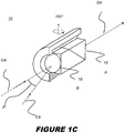
- FIG. 1C shows Rochon polarizer 10 with a reversed orientation, with respect to incident light, compared with Figure 1A and 1B orientations.
- Rochon polarizer 10 in Figure 1C is disposed to receive, at what is designated its B- face 16, polarized light of different polarization states, with light of one polarization state at incident angle ⁇ , and to direct light of either polarization state onto optical axis OA at its A-face 15.
- these input A-/ output B-face designations used herein are arbitrarily assigned, but are the same for two paired composite birefringent prisms of the same type and must be identified in order to dispose each prism in its proper orientation for polarization switching in embodiments of the present invention.
- Embodiments of the present invention provide a polarization switching apparatus that takes advantage of the broadband performance of Rochon and similar birefringent polarizers formed from crystalline materials and provides improved switching speed by eliminating the requirement for a motor or other actuator to spin the polarizer about the optical axis.
- embodiments of the present invention provide polarization switching that allows up to three output states, so that the output light can alternately be of a first polarization only, or of a second polarization only, or of both polarizations, or a suitable combination of these states.
- Beam redirection optics compensate for differences in refraction due to wavelength, so that the output beam does not deviate in spatial position when switched from one polarization state to the other.
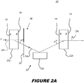
- FIGS. 2A and 2B show a polarization switching apparatus 20 consistent with an embodiment of the present invention.
- Switching apparatus 20 has a first or input polarizer 22a and a second or output polarizer 22b, both aligned along optical axis OA and in reversed orientation with respect to each other.
- Input polarizer 22a separates the incident light I according to its polarization axis.
- Light of a first polarization state continues undeviated along the optical axis OA.
- Light of a second orthogonal polarization state is redirected by redirecting optics 30 along an extraordinary axis EA toward a reflective element 28, such as a mirror.
- a shutter element 24 is arranged in the path of the output light from polarizer 22a to block or allow light of either polarization state. In one position, as in Figure 2A , shutter element 24 blocks the light that would otherwise travel along the path of optical axis OA. In Figure 2B , the position of shutter element 24 blocks the light along the path of extraordinary axis EA.
- second or output polarizer 22b In Figures 2A and 2B , second or output polarizer 22b, reversed in orientation from polarizer 22a and acting as described in Figure 1C , combines the reflected EA light path with the undeviated OA path to provide output light of either polarization state, as switched according to shutter element 24, along the optical axis OA.
- Second polarizer 22b is reversed in A/B orientation relative to first polarizer 22a and functions in reverse, so that light of the orthogonal polarization that is incident along extraordinary axis EA is output along optical axis OA. With this configuration, polarizers 22a and 22b are stationary.
- Shutter apparatus 46 have one shutter element 24 for alternately blocking light of the first or second polarization, depending on the configuration.
- a single shutter element 24 can also have positions for blocking all of the light, or none of the light, along the light paths between polarizers 22a and 22b.
- the use of a single shutter element 24, as shown in the examples of Figures 2A and 2B is advantaged for reducing the number of components needed as part of shutter apparatus 46 and allows for the use of a smaller shutter element 24, disposed in proximity to either polarizer 22a or 22b.
- a pair of shutter elements 24 are used for shutter apparatus 46, actuable in a synchronized manner so that one of the pair of shutter elements 24 is on, blocking one light path, while the other shutter element 24 in the pair is off.
- paired shutter elements 24 are independently actuable to allow light along both, either, or neither light paths.
- Shutter element 24 can be a lightweight shutter device for blocking or deflecting light, and can be actuated using a galvanometer or other lightweight actuator that has sufficient speed for the needed switching. Low power is also an advantage with a galvanometric actuator. Consistent with an embodiment of the present invention, shutter element 24 has three effective positions: blocking the internal OA path in a first position as in Figure 2A ; blocking the internal EA path in a second position as in Figure 2B ; or blocking neither path in a third position, thus allowing both polarizations at the output of polarization switching apparatus 20 in this third position. An alternate fourth position allows shutter element 24 to block all of the light.
- Shutter apparatus 46 can have any suitable control logic arrangement for actuating one or more shutter elements 24 from one state to another, using techniques well known in the optical device arts.
- reflective element 28 can be a mirror or reflective dichroic or other surface disposed in the path of extraordinary axis EA or, alternately, in the path of optical axis OA.
- redirecting optics 30 includes two reflective elements 28a and 28b, two mirrors or other reflectors, such as dichroic reflectors, for example, that are arranged to revert the image of the redirected beam.
- Redirecting optics 30 can be any of a number of types of reflective elements, such as mirrors or coated surfaces, as well as refractive elements, such as prisms and lenses.
- the Rochon polarizer 10 is achromatic for light of the polarization state that is directed along optical axis OA.
- refraction varies by wavelength.
- angle ⁇ in Figures 1A, 1B and 2A, 2B is wavelength-dependent.
- Angle ⁇ is generally larger for light of shorter wavelengths.
- Figures 4A and 4B show an embodiment of polarization switching apparatus 20 that adapts for differences in wavelength.
- the extraordinary axis EA diverges from the optical axis OA at an angle ⁇ 1 .
- An actuator 38 positions reflective element 28 so that light at this angle is redirected at the proper angle toward polarizer 22b.
- Figure 4B shows reflective element 28 moved to a different position for redirecting light at a shorter wavelength, where the extraordinary axis EA diverges from the optical axis OA at a larger angle ⁇ 2 .
- the earlier position of reflective element 28 is shown in phantom lines at 28'.
- FIG. 5A and schematic diagram of Figure 5B show an alternate example not covered by the present invention in which redirecting optics 30 uses a refractive element, with a refracting prism 32 to redirect light of the second polarization state back toward the second polarizer 22b.
- Shutter apparatus 46 is a mechanism having two motors as actuators 40, with each motor used to rotate an actuated shutter element 24 into position, either obstructing the light path or providing an aperture for the light. In the embodiment shown in Figures 5A and 5B , shutter apparatus 46 thus has two shutter elements 24 that cooperate to block alternate light paths appropriately.
- One difficulty with the single-prism arrangement of Figure 5A relates to the wavelength of light incident to prism 32 and to its angle of minimum deviation ⁇ m , which changes according to the wavelength of the incident light.
- ⁇ m the angle of minimum deviation
- the angle of incidence on a first or incidence face 44a of prism 32 is equal to the angle of exitance of the beam at a second or exit face 44b of prism 32.
- the beam subtends the same size on both faces, without magnification or demagnification of the beam by the prism in the refracting direction.
- magnification of the beam may not be a consideration; however, in precision measurement applications, changes in beam size at different wavelengths can be highly undesirable.
- FIG. 5B The schematic side view of Figure 5B shows what happens when conditions for the angle of minimum deviation ⁇ m are satisfied for one wavelength and not satisfied for another.
- Light at one wavelength shown in solid lines along extraordinary axis EA3, is at the angle of minimum deviation relative to prism 32 and is redirected from polarizer 22a to polarizer 22b.
- Light at another wavelength is shown in dashed lines along extraordinary axis EA4. This light misses second polarizer 22b altogether.
- prism 32 When arranged to provide minimum deviation, prism 32 is equidistant from polarizers 22a and 22b. The angle of minimum deviation is twice the deviation angle ⁇ from the first polarizer 22a. Prism 32 has a prism angle ⁇ , also termed a prism apex angle, and shown by dashed lines in Figure 5B .
- n Sin ⁇ + ⁇ m / 2 Sin ⁇ / 2
- the index n of the refractive material of prism 32 is one function of wavelength
- the deviation angle ⁇ of the second polarization at the first polarizer 22a is another function of wavelength.
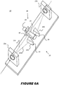
- FIG. 6A and schematic view of Figure 6B show an alternate embodiment of the present invention that surmounts this difficulty and provides a way to adapt to the angle of minimum deviation ⁇ m .
- redirecting optics 30 utilize two refractive prisms 32 and 34 for redirecting light toward polarizer 22b. These prism components are symmetrically pivoted to actively accommodate wavelength-dependent alignment characteristics. With this arrangement, paired prisms 32 and 34 effectively act as a single prism, adjustable to satisfy the angular conditions for minimum deviation at a given wavelength.
- the angle of light at incidence face 44a is the same as the angle of exiting light at exit face 44b. Symmetry is about a plane of bisymmetry B, orthogonal to the page of Figure 6B .
- the light between prisms 32 and 34 is normal to the plane of bisymmetry B and, in embodiments of switching apparatus 20 shown herein, parallel to the optical axis OA.
- light along different axes EA3 and EA4 from the first polarizer 22a can be directed to second polarizer 22b with proper adjustment of prism 32 and 34 angle.
- the two prisms 32 and 34 are identical in shape and are rotated in equal but opposite directions when switching wavelengths. Prisms 32 and 34 are manually pivoted or pivoted automatically using optional actuator 38.
- the two prisms and their respective pivot points are symmetrically arranged, so that the pivot point of each prism 32 and 34 is the same distance from the nearest respective polarizer 22a or 22b and the same distance from the optical axis OA. It can be observed that other arrangements using two or more movable prisms to provide minimum deviation at different wavelengths are possible, including more complex configurations than those shown in Figure 6B .
- Shutter elements 24 in the Figure 5A and 6A embodiments have a rotated tube with apertures 48 that align with the light along axes OA and EA at various positions.
- Shutter element 24 can have a number of different positions and states, such as with one position for each polarization state individually, one for both polarization states, and another position for neither polarization state, blocking all light. It can be appreciated that any of a number of alternate types of shutter mechanism can be used with shutter elements 24 positioned at any suitable location along the light paths, before, after, or within redirecting optics 30.
- FIG. 7 shows an alternate embodiment of the present invention in which redirecting optics 30 use third and fourth composite birefringent polarizers 50a and 50b to redirect the light of the second polarization state back toward second polarizer 22b.
- Birefringent polarizers 50a and 50b such as Rochon polarizers, are disposed in reversed orientation relative to each other, as described previously with reference to the first and second polarizers 22a and 22b.
- the arrangement of Figure 7 helps to accommodate chromatic dependencies for light of the second polarization state, including variability in the EA angle due to wavelength.
- the Figure 7 embodiment does not require movement of any of the redirecting optics 30 components for a change in wavelength.
- light along both axes EA3 and EA4 is accommodated, as well as light at angles between those of axes EA3 and EA4.
- the Rochon polarizer is advantaged for its broad spectral range, including the capability for handling light in the deep ultraviolet (DUV) region, such as around 200 nm. It should be observed that other types of birefringent polarizers could alternately be used, over appropriate wavelength ranges and power levels.
- Composite prism solutions such as the Wollaston, Senarmont, or Glan-Foucalt prisms could alternately be used for input and output polarizers 22a and 22b, for example, or for polarizers 50a and 50b used in redirecting optics, as was shown in Figure 7 , with appropriate redirection optics for the different polarization states.
- FIG. 8 is a schematic view that shows an alternate embodiment of apparatus 20 with paired reflective elements folding the light path of the extraordinary axis for light of the second polarization, according to wavelength.
- Actuator 38 adjusts the reflective element angles and positions needed for redirecting light of different wavelengths to the second polarizer 22b.
- axis EA2 is folded by paired reflectors at alternate positions shown for reflective elements 28a and 28b.
- axis EA1 is folded by paired reflectors at positions shown for reflective elements 26a and 26b. These may be the same pair of reflectors at different positions or may be reflectors that are provided in fixed positions for particular wavelengths.
- all wavelengths are directed along optical axis OA. It should be noted that reflective elements at positions shown for elements 28a and 26a can be interpreted as alternative positions of the same mirror or other movable reflective surface.
- a single mirror is translated to a position that is suitable for the wavelength of incident light.
- the mirror is positioned at or nearer the position shown for reflective element 28a.
- the mirror is positioned at or nearer the reflector positioned at reflective element 26a.
- the paired mirror is symmetrically placed in appropriate positions as reflective elements 26b and 28b.
- mirrors can be automatically actuated to translate and rotate to the appropriate position and angle. Alternately, manual mirror adjustment can be used.
- Embodiments of the present invention can be packaged as part of a measurement apparatus, for example, allowing automated measurement of surface or physical characteristics using light over a range of wavelengths and with or without concern for polarization state.
- the polarization switching apparatus of the present invention handles light over a broad range of wavelengths, allows fast switching and reconfiguration, and allows light of either polarization or, alternately, all incident light to be projected toward a target. Alternately, all incident light can be blocked as needed.
- a four-state shutter apparatus 46 can be provided, so that polarization switching apparatus 20 allows light of a first polarization state, light of a second polarization state, light of all polarization states, or no light to be provided at the output.
Landscapes
- Physics & Mathematics (AREA)
- Spectroscopy & Molecular Physics (AREA)
- General Physics & Mathematics (AREA)
- Chemical & Material Sciences (AREA)
- Health & Medical Sciences (AREA)
- Life Sciences & Earth Sciences (AREA)
- Optics & Photonics (AREA)
- Analytical Chemistry (AREA)
- Biochemistry (AREA)
- General Health & Medical Sciences (AREA)
- Immunology (AREA)
- Pathology (AREA)
- Polarising Elements (AREA)
- Mechanical Light Control Or Optical Switches (AREA)
Description
- This application claims the benefit of
U.S. Provisional Patent Application Serial No. 61/536686, filed on September 20, 2011 - This invention generally relates to optical apparatus for selecting polarized light in an optical system and more particularly relates to a broadband polarization switching apparatus capable of switching polarized light over a broad wavelength range that includes light in the deep ultraviolet range.
- In high performance optical metrology and inspection systems, such as those used for semiconductor wafer inspection, the industry trend is to inspect a sample using multiple optical configurations in a serial fashion. The configuration options may include wavelength, illumination partial coherence (illumination sigma), and polarization state. In order to have high throughput, the optical configurations of the inspection system must be switched from one to the next in a very short time while imparting negligible levels of shock and vibration to the inspection system.
- Although there are a number of types of polarizers, many types of polarizers are constrained to particular spectral bands and perform poorly with light outside the intended band. Thin-film polarizers, for example, are typically designed for narrow spectral bands, centered about a nominal wavelength. Wire grid polarizers work best primarily for handling light in the infrared region. Electro-optic and acousto-optic devices have limited spectral bandwidth and power ranges. The use of half-wave retarding plates in conjunction with static polarizers is not practical for broadband light and will not work for the full range of light that extends from deep ultraviolet (DUV, such as around 200nm) to infrared (IR, such as around 800 nm). Still other polarizer types may work well in specific spectral regions and very poorly in others.
- For performance over a broad range of wavelengths that include the DUV region, the selection is more limited. Polarizers that operate in this range and that meet the requirements for broad range operation are generally composite devices that use paired arrangements of birefringent crystals, coupled together along an interface and disposed at an appropriate position and angle in the light path for polarizing the incident light. Devices of this type, however, are typically large in volume and in mass. This makes it difficult to switch the polarization state quickly and without imparting some amount of shock and vibration to the inspection system.
- Thus, although various types of polarization switching apparatus are used in narrow-band applications, these solutions are not suitable for broadband application, particularly where the spectral range spans the DUV wavelengths. There is, then, a need for a broadband polarization switching apparatus that is capable of handling light in the DUV region, but without requiring rotation of the polarizer itself as part of the switching operation.
- Document
US 6 124 928 discloses a polarization switching apparatus using polarisation beam splitters and shutter elements. DocGB 885 261 - To advance the art of polarization switching, such as is needed for optical metrology and inspection systems, embodiments of the present invention use an arrangement of polarizers and shutter devices that allow the handling of broadband light and allow the use of either of two orthogonal polarization states or, optionally, of all polarization states. Advantageously, embodiments of the present invention allow switching of polarization states at high speeds without the need to rotate the polarizers themselves.
- According to an aspect of the present invention, there is provided a polarization switching apparatus according to claim 1.
- Other desirable objectives, features, and advantages of the disclosed invention may occur or become apparent to those skilled in the art. The invention is defined by the appended claims.
-
-
Figure 1A is a perspective view that shows a Rochon polarizer separating light of first and second polarizations in a first rotational orientation. -
Figure 1B is a perspective view that shows a Rochon polarizer separating light of first and second polarizations, with the polarizer rotated to a second rotational orientation. -
Figure 1C is a perspective view that shows a Rochon polarizer combining light of first and second polarizations, incident at different angles, onto the optical axis. -
Figure 2A is a schematic block diagram that shows a broadband polarization switching apparatus using a pair of polarizers and a reflective surface, with a shutter element to block light of an undeviated first polarization state, allowing transmission of the orthogonal polarization state. -
Figure 2B is a schematic block diagram that shows the use of a shutter element to block light of a deviated second polarization state, allowing transmission of the orthogonal first polarization state. -
Figure 3 is a schematic block diagram that shows a broadband polarization switching apparatus using a pair of polarizers and a pair of reflective surfaces. -
Figures 4A and4B show an adjustment of beam redirector position according to wavelength. -
Figure 5A is a perspective view that shows a broadband polarization switching apparatus using a redirecting prism in the path of the deviated polarization state. -
Figure 5B is a schematic diagram for the apparatus shown inFigure 5A . -
Figure 6A is a perspective view that shows a broadband polarization switching apparatus using a pair of redirecting prisms in the path of the deviated polarization state. -
Figure 6B is a schematic diagram for the apparatus shown inFigure 6A . -
Figure 7 is a schematic view that shows a broadband polarization switching apparatus using a second pair of polarizers in the path of the deviated light of the second polarization state. -
Figure 8 is a schematic view that shows an alternate embodiment with paired reflectors folding the light path. - Figures shown and described herein are provided in order to illustrate key principles of operation and fabrication for an optical apparatus according to various embodiments and a number of these figures are not drawn with intent to show actual size or scale. Some exaggeration may be necessary in order to emphasize basic structural relationships or principles of operation.
- Where they are used in the present disclosure, the terms "first", "second", and so on, do not necessarily denote any ordinal or priority relation, but are used for more clearly distinguishing one element from another. There are no fixed "first" or "second" elements in what is taught herein; these descriptors are merely used to clearly distinguish one element from another similar element in the context of the present disclosure, such as in the order in which like parts are referenced. The term "actuable" has its conventional meaning, relating to a device or component that is capable of effecting an action in response to a stimulus, such as in response to an electrical signal, for example.
- In the context of the present disclosure, the term "oblique" means at an angle that is not an integer multiple of 90 degrees. Two beams, for example, are considered to be oblique with respect to each other if they diverge from or converge toward each other at an angle that is at least about 2 degrees or more away from parallel, or at least about 2 degrees or more away from orthogonal.
- The term "prism" or "prism element" is used herein as it is understood in optics, to refer to a transparent optical element that is generally in the form of an n-sided polyhedron with flat surfaces upon which light is incident and that is formed from a transparent, solid material that refracts light. It is understood that, in terms of shape and surface outline, the optical understanding of what constitutes a prism is less restrictive than the formal geometric definition of a prism and encompasses that more formal definition. In optics, for example, the term "prism" is also used in reference to a composite element, formed from two or more component prism elements that are glued or otherwise coupled together, including composite elements that are mechanically coupled but have an air gap at the interface between them.
- In the context of the present disclosure, the term "broadband" is used to denote a spectral range that at least exceeds about 50 nm. Embodiments of the present invention are not only able to provide polarization switching over a broadband range, but can provide this switching for wavelengths that extend into the deep ultraviolet (DUV) region, for switching light provided by excimer lasers, for example, that emit light below 200 nm. This range, inaccessible to many types of conventional polarizers, can be handled by a birefringent polarizer formed as a sectioned or composite birefringent prism, that is, formed by coupling blocks or wedges of birefringent crystal material.
- There are a number of types of composite birefringent prisms. One composite prism of this type is the Rochon polarizer, formed from two birefringent crystal wedges, each wedge termed a component crystal or component prism in the present disclosure. The pair of component crystals are typically cemented together or are otherwise maintained in optical contact at an interface. Alternately, the birefringent component crystals can be coupled to a frame or other holder that maintains a precise, narrow air spacing between them. Typically formed from crystalline materials such as quartz, MgF2, YVO4, alpha-BBO (barium borate), rutile (TiO2), sodium nitrate, or tourmaline, the Rochon polarizer advantageously exhibits a high extinction ratio and has a high damage threshold.
- For any of the various types of composite birefringent prisms, the behavior of the prism with respect to incident polarized light depends, in large part, on the optic axis of the crystal material itself. Light that is polarized in parallel to the optic axis of the crystal may be separated from and diverge from light that is polarized perpendicular to the optic axis. This complicates the task of describing the relative polarization states of incident and output light, since, in addition to its position, the orientation and rotation of the composite birefringent prism with respect to the optical system can determine how polarized light behaves. This can be a particular source of confusion in describing an optical system, since the "optic axis" of a crystal may be orthogonal to, or at some other non-zero angle to, what is considered the optical axis for the system itself. For this reason, unless otherwise specified, references in the present disclosure to "optical axis" do not refer to the optic axis of a composite birefringent prism or of its component crystals, but instead refer to the optical axis of the overall polarization switching system that includes the birefringent prisms and other components, as described in detail subsequently.
-
Figure 1A is a perspective view that shows aRochon polarizer 10 separating light of first and second polarizations. In the orientation shown,polarizer 10 lies along the optical axis OA and provides light of a first polarization state, shown as P-polarized light, parallel to the page, output along axis OA as an ordinary beam. Light of a second polarization state, orthogonal to the P-polarized light and shown as S-polarized light, is redirected as an extraordinary beam, at an angle θ, to axis OA. In conventional use, Rochon polarizer 10 can be rotated 1/4 turn (90 degrees) about the OA to switch the polarization state of light along axis OA, as shown inFigure 1B . InFigure 1B , the "P" and "S" designations are given to describe polarization states with reference to the assignments shown inFigure 1A . As can be seen fromFigures 1A and 1B , rotation of theRochon polarizer 10 about optical axis OA determines the polarization state of light that exits on that axis. Angle θ between extraordinary axis EA and optical axis OA is oblique, diverging at least about 2 degrees from parallel. The direction of the deviation for this axis follows the orientation of the wedge interface between the component crystals. - Using the principle shown in
Figures 1A and 1B , a simple polarization switcher can be formed using asingle Rochon polarizer 10. A polarization switcher of this type simply rotatespolarizer 10 to either of two rotational positions about the optical axis in order to switch between first and second mutually orthogonal polarization states. This can provide a broadband switching polarizer, but there are drawbacks with this switching technique. Significantly, the relative size and mass of the Rochon polarizer constrains the switching speed. In addition, actuator vibration and shock and mechanical tolerances for precision positioning also limit the feasibility of this approach. Thus, a polarization switcher using a rotatable Rochon polarizer would not serve well in an inspection or measurement environment where high-speed switching is needed. - The specific behavior of the Rochon polarizer and similar types of birefringent composite polarizers depends on the arrangement of their component wedges, the angle of the interface between the components, the crystalline material used, and the optic axes of the crystal components. As shown in
Figures 1A and 1B , the birefringent prism that forms the Rochon polarizer has an input or A-face 15 and an output or B-face 16. Input and output face designations are arbitrary, since these polarizers, when used singly, can be used in either direction. However, it is important to note that, due to interface angle between component prisms and geometry,prism 10 behavior is slightly different depending on whether the A-face 15 or the B-face 16 serves as the input face in the path of incident light. Embodiments of the present invention used matched pairs of Rochon or other birefringent composite prisms, with the two paired prisms disposed in opposite orientation, that is, with one polarizer in reversed orientation from the other, so that the input face/output face or A/B face designations of the two prisms in the pair are the reverse of each other. -
Figure 1C showsRochon polarizer 10 with a reversed orientation, with respect to incident light, compared withFigure 1A and 1B orientations.Rochon polarizer 10 inFigure 1C is disposed to receive, at what is designated its B-face 16, polarized light of different polarization states, with light of one polarization state at incident angle θ, and to direct light of either polarization state onto optical axis OA at itsA-face 15. Again, these input A-/ output B-face designations used herein are arbitrarily assigned, but are the same for two paired composite birefringent prisms of the same type and must be identified in order to dispose each prism in its proper orientation for polarization switching in embodiments of the present invention. - Embodiments of the present invention provide a polarization switching apparatus that takes advantage of the broadband performance of Rochon and similar birefringent polarizers formed from crystalline materials and provides improved switching speed by eliminating the requirement for a motor or other actuator to spin the polarizer about the optical axis. In addition, embodiments of the present invention provide polarization switching that allows up to three output states, so that the output light can alternately be of a first polarization only, or of a second polarization only, or of both polarizations, or a suitable combination of these states. Beam redirection optics compensate for differences in refraction due to wavelength, so that the output beam does not deviate in spatial position when switched from one polarization state to the other.
- The schematic diagram of
Figures 2A and2B show apolarization switching apparatus 20 consistent with an embodiment of the present invention.Switching apparatus 20 has a first orinput polarizer 22a and a second oroutput polarizer 22b, both aligned along optical axis OA and in reversed orientation with respect to each other.Input polarizer 22a separates the incident light I according to its polarization axis. Light of a first polarization state continues undeviated along the optical axis OA. Light of a second orthogonal polarization state is redirected by redirectingoptics 30 along an extraordinary axis EA toward areflective element 28, such as a mirror. Reflection at a low or "grazing" angle is advantaged for preserving the polarization state of the incident light. As part of ashutter apparatus 46, ashutter element 24 is arranged in the path of the output light frompolarizer 22a to block or allow light of either polarization state. In one position, as inFigure 2A ,shutter element 24 blocks the light that would otherwise travel along the path of optical axis OA. InFigure 2B , the position ofshutter element 24 blocks the light along the path of extraordinary axis EA. - In
Figures 2A and2B , second oroutput polarizer 22b, reversed in orientation frompolarizer 22a and acting as described inFigure 1C , combines the reflected EA light path with the undeviated OA path to provide output light of either polarization state, as switched according toshutter element 24, along the optical axis OA.Second polarizer 22b is reversed in A/B orientation relative tofirst polarizer 22a and functions in reverse, so that light of the orthogonal polarization that is incident along extraordinary axis EA is output along optical axis OA. With this configuration,polarizers -
Shutter apparatus 46 have oneshutter element 24 for alternately blocking light of the first or second polarization, depending on the configuration. Asingle shutter element 24 can also have positions for blocking all of the light, or none of the light, along the light paths betweenpolarizers single shutter element 24, as shown in the examples ofFigures 2A and2B , is advantaged for reducing the number of components needed as part ofshutter apparatus 46 and allows for the use of asmaller shutter element 24, disposed in proximity to eitherpolarizer shutter elements 24 are used forshutter apparatus 46, actuable in a synchronized manner so that one of the pair ofshutter elements 24 is on, blocking one light path, while theother shutter element 24 in the pair is off. In yet another alternate example pairedshutter elements 24 are independently actuable to allow light along both, either, or neither light paths. -
Shutter element 24 can be a lightweight shutter device for blocking or deflecting light, and can be actuated using a galvanometer or other lightweight actuator that has sufficient speed for the needed switching. Low power is also an advantage with a galvanometric actuator. Consistent with an embodiment of the present invention,shutter element 24 has three effective positions: blocking the internal OA path in a first position as inFigure 2A ; blocking the internal EA path in a second position as inFigure 2B ; or blocking neither path in a third position, thus allowing both polarizations at the output ofpolarization switching apparatus 20 in this third position. An alternate fourth position allowsshutter element 24 to block all of the light.Shutter apparatus 46 can have any suitable control logic arrangement for actuating one ormore shutter elements 24 from one state to another, using techniques well known in the optical device arts. In the redirectingoptics 30 configuration shown inFigures 2A and2B ,reflective element 28 can be a mirror or reflective dichroic or other surface disposed in the path of extraordinary axis EA or, alternately, in the path of optical axis OA. - In the alternate embodiment shown in
Figure 3 , redirectingoptics 30 includes tworeflective elements optics 30 can be any of a number of types of reflective elements, such as mirrors or coated surfaces, as well as refractive elements, such as prisms and lenses. - The Rochon polarizer 10 is achromatic for light of the polarization state that is directed along optical axis OA. For light having the orthogonal polarization state, refraction varies by wavelength. Thus, angle θ in
Figures 1A, 1B and 2A, 2B , for example, is wavelength-dependent. Angle θ is generally larger for light of shorter wavelengths. -
Figures 4A and4B show an embodiment ofpolarization switching apparatus 20 that adapts for differences in wavelength. InFigure 4A , with incident light I at a first wavelength, the extraordinary axis EA diverges from the optical axis OA at an angle θ1. An actuator 38 positionsreflective element 28 so that light at this angle is redirected at the proper angle towardpolarizer 22b.Figure 4B showsreflective element 28 moved to a different position for redirecting light at a shorter wavelength, where the extraordinary axis EA diverges from the optical axis OA at a larger angle θ2. For reference, the earlier position ofreflective element 28 is shown in phantom lines at 28'. - The perspective view of
Figure 5A and schematic diagram ofFigure 5B show an alternate example not covered by the present invention in which redirectingoptics 30 uses a refractive element, with a refractingprism 32 to redirect light of the second polarization state back toward thesecond polarizer 22b.Shutter apparatus 46 is a mechanism having two motors asactuators 40, with each motor used to rotate an actuatedshutter element 24 into position, either obstructing the light path or providing an aperture for the light. In the embodiment shown inFigures 5A and5B ,shutter apparatus 46 thus has twoshutter elements 24 that cooperate to block alternate light paths appropriately. - One difficulty with the single-prism arrangement of
Figure 5A relates to the wavelength of light incident toprism 32 and to its angle of minimum deviation δm , which changes according to the wavelength of the incident light. Briefly, when a beam refracts throughprism 32 at the angle of minimum deviation, the angle of incidence on a first orincidence face 44a ofprism 32 is equal to the angle of exitance of the beam at a second orexit face 44b ofprism 32. When incidence and exitance angles are equal, the beam subtends the same size on both faces, without magnification or demagnification of the beam by the prism in the refracting direction. In some applications, magnification of the beam may not be a consideration; however, in precision measurement applications, changes in beam size at different wavelengths can be highly undesirable. - The schematic side view of
Figure 5B shows what happens when conditions for the angle of minimum deviation δm are satisfied for one wavelength and not satisfied for another. Light at one wavelength, shown in solid lines along extraordinary axis EA3, is at the angle of minimum deviation relative toprism 32 and is redirected frompolarizer 22a topolarizer 22b. Light at another wavelength is shown in dashed lines along extraordinary axis EA4. This light missessecond polarizer 22b altogether. - When arranged to provide minimum deviation,
prism 32 is equidistant frompolarizers first polarizer 22a.Prism 32 has a prism angle α, also termed a prism apex angle, and shown by dashed lines inFigure 5B . - For a prism angle α, the relationship between the refractive index of the prism (n) and the angle of minimal deviation δm is given by:

- The index n of the refractive material of
prism 32 is one function of wavelength, and the deviation angle θ of the second polarization at thefirst polarizer 22a is another function of wavelength. After taking into account both of these functions, it is possible to derive an equation of the optimum prism angle α, as a function of wavelength, to meet the requirement for minimum deviation. In the case ofFigure 5A and5B however, with a single prism formed with a set angle α, minimum deviation is satisfied only at one wavelength. It is possible to align the beam to the second polarizer outside of minimum deviation by rotating and translatingprism 32, but the beam changes width in the refracting direction when this happens and will no longer match the width of the beam of the first polarization. Thus, even whereprism 32 can be rotated or repositioned, some change in beam magnification results at other wavelengths. - The perspective view of
Figure 6A and schematic view ofFigure 6B show an alternate embodiment of the present invention that surmounts this difficulty and provides a way to adapt to the angle of minimum deviation δm . Here, redirectingoptics 30 utilize tworefractive prisms polarizer 22b. These prism components are symmetrically pivoted to actively accommodate wavelength-dependent alignment characteristics. With this arrangement, pairedprisms incidence face 44a is the same as the angle of exiting light atexit face 44b. Symmetry is about a plane of bisymmetry B, orthogonal to the page ofFigure 6B . At minimum deviation, the light betweenprisms apparatus 20 shown herein, parallel to the optical axis OA. By comparison withFigure 5B , light along different axes EA3 and EA4 from thefirst polarizer 22a can be directed tosecond polarizer 22b with proper adjustment ofprism - In the example shown in
Figure 6B , the twoprisms Prisms optional actuator 38. The two prisms and their respective pivot points are symmetrically arranged, so that the pivot point of eachprism respective polarizer Figure 6B . -
Shutter elements 24 in theFigure 5A and6A embodiments have a rotated tube withapertures 48 that align with the light along axes OA and EA at various positions.Shutter element 24 can have a number of different positions and states, such as with one position for each polarization state individually, one for both polarization states, and another position for neither polarization state, blocking all light. It can be appreciated that any of a number of alternate types of shutter mechanism can be used withshutter elements 24 positioned at any suitable location along the light paths, before, after, or within redirectingoptics 30. - The schematic view of
Figure 7 shows an alternate embodiment of the present invention in which redirectingoptics 30 use third and fourth compositebirefringent polarizers second polarizer 22b.Birefringent polarizers second polarizers Figure 7 helps to accommodate chromatic dependencies for light of the second polarization state, including variability in the EA angle due to wavelength. Unlike the embodiment shown inFigures 6A and6B , theFigure 7 embodiment does not require movement of any of the redirectingoptics 30 components for a change in wavelength. As shown inFigure 7 , for example, light along both axes EA3 and EA4 is accommodated, as well as light at angles between those of axes EA3 and EA4. - The Rochon polarizer is advantaged for its broad spectral range, including the capability for handling light in the deep ultraviolet (DUV) region, such as around 200 nm. It should be observed that other types of birefringent polarizers could alternately be used, over appropriate wavelength ranges and power levels. Composite prism solutions such as the Wollaston, Senarmont, or Glan-Foucalt prisms could alternately be used for input and
output polarizers polarizers Figure 7 , with appropriate redirection optics for the different polarization states. - Consistent with an embodiment of the present invention, another type of adjustment for wavelength relates to reflector angle.
Figure 8 is a schematic view that shows an alternate embodiment ofapparatus 20 with paired reflective elements folding the light path of the extraordinary axis for light of the second polarization, according to wavelength.Actuator 38 adjusts the reflective element angles and positions needed for redirecting light of different wavelengths to thesecond polarizer 22b. - At shorter wavelengths, axis EA2 is folded by paired reflectors at alternate positions shown for
reflective elements reflective elements elements reflective element 28a. For relatively longer wavelengths, the mirror is positioned at or nearer the reflector positioned atreflective element 26a. The paired mirror is symmetrically placed in appropriate positions asreflective elements - Embodiments of the present invention can be packaged as part of a measurement apparatus, for example, allowing automated measurement of surface or physical characteristics using light over a range of wavelengths and with or without concern for polarization state. Advantageously, the polarization switching apparatus of the present invention handles light over a broad range of wavelengths, allows fast switching and reconfiguration, and allows light of either polarization or, alternately, all incident light to be projected toward a target. Alternately, all incident light can be blocked as needed. In this way, a four-
state shutter apparatus 46 can be provided, so thatpolarization switching apparatus 20 allows light of a first polarization state, light of a second polarization state, light of all polarization states, or no light to be provided at the output. - The invention has been described in detail with particular reference to certain preferred embodiments thereof, but it will be understood that variations and modifications can be effected within the scope of the invention as described above, and as noted in the appended claims, by a person of ordinary skill in the art without departing from the scope of the invention.
Claims (10)
- A polarization switching apparatus comprising:a first birefringent polarizer (22a) formed as a composite prism and disposed to direct incident light of a first polarization along a first optical path and light of a second polarization along a second optical path, wherein the second optical path is oblique with respect to the first optical path;a beam redirector (28) disposed to redirect the first optical path from the first birefringent polarizer toward an input face of a second birefringent polarizer (22b); wherein the second birefringent polarizer is also formed as a composite prism and is disposed to combine incident light of the first and second polarizations onto a common output path;
anda single shutter (24) that is actuable to: (a) selectively block light of the first polarization or light of the second polarization from the input face of the second birefringent polarizer, or (b) allow both light of the first polarization and light of the second polarization to pass. - The polarization switching apparatus of claim 1 wherein at least the first birefringent polarizer is a Rochon polarizer.
- The polarization switching apparatus of claim 1 wherein the first birefringent polarizer comprises component prisms formed from one or more of calcite, quartz, MgF2, YVO4, or alpha-BBO (barium borate).
- The polarization switching apparatus of claim 1 wherein the shutter is further actuable to selectively block light of both first and second polarizations.
- The polarization switching apparatus of claim 1 wherein the beam redirector comprises at least one reflective element.
- The polarization switching apparatus of claim 1 wherein the beam redirector comprises a third polarizer and a fourth polarizer.
- The apparatus of claim 1 wherein the beam redirector comprises at least one prism.
- The polarization switching apparatus of claim 1 wherein the shutter apparatus has an actuator taken from the group consisting of a galvanometric actuator and a motor.
- The apparatus of claim 1 wherein the first and second polarizers comprise crystalline materials and provide polarization of light having wavelengths in the ultraviolet region from about 200 nm to 250 nm.
- The apparatus of claim 1 wherein the beam redirector comprises two prisms that are each movable to adjust for angle of minimum deviation.
Applications Claiming Priority (2)
| Application Number | Priority Date | Filing Date | Title |
|---|---|---|---|
| US201161536686P | 2011-09-20 | 2011-09-20 | |
| PCT/US2012/054089 WO2013043386A1 (en) | 2011-09-20 | 2012-09-07 | Broadband polarization switching |
Publications (2)
| Publication Number | Publication Date |
|---|---|
| EP2758827A1 EP2758827A1 (en) | 2014-07-30 |
| EP2758827B1 true EP2758827B1 (en) | 2017-06-28 |
Family
ID=47040781
Family Applications (1)
| Application Number | Title | Priority Date | Filing Date |
|---|---|---|---|
| EP12773428.3A Not-in-force EP2758827B1 (en) | 2011-09-20 | 2012-09-07 | Broadband polarization switching |
Country Status (3)
| Country | Link |
|---|---|
| US (1) | US8830581B2 (en) |
| EP (1) | EP2758827B1 (en) |
| WO (1) | WO2013043386A1 (en) |
Families Citing this family (4)
| Publication number | Priority date | Publication date | Assignee | Title |
|---|---|---|---|---|
| DE102013103282A1 (en) * | 2013-04-02 | 2014-10-02 | Carl Zeiss Laser Optics Gmbh | Polarizer arrangement for spatially separating polarization states of a light beam |
| NL2013443B1 (en) * | 2014-09-09 | 2016-09-28 | Nederlands Forensisch Inst | An apparatus and method for analyzing a birefringent sample. |
| EP3009877A1 (en) * | 2014-10-15 | 2016-04-20 | Optosys SA | Device for emission of polarized light and its detection |
| US10914916B2 (en) * | 2017-03-07 | 2021-02-09 | Onto Innovation Inc. | Non-adhesive mounting assembly for a tall Rochon polarizer |
Family Cites Families (18)
| Publication number | Priority date | Publication date | Assignee | Title |
|---|---|---|---|---|
| GB885261A (en) | 1959-12-18 | 1961-12-20 | Roussel Uclaf | Improvements in or relating to polarimeters |
| US4187803A (en) | 1971-08-09 | 1980-02-12 | Oil-Dri Corporation Of America | Process for pelletizing sorptive mineral fines |
| US4059343A (en) * | 1976-02-26 | 1977-11-22 | The United States Of America As Represented By The Secretary Of The Air Force | Prismatic anamorphic system for optical correlators |
| US5276747A (en) | 1993-01-21 | 1994-01-04 | E-Tek Dynamics, Inc. | Polarization-independent optical switch/attenuator |
| EP0653660A1 (en) * | 1993-11-12 | 1995-05-17 | AT&T Corp. | Optical isolator with reduced walk-off |
| US5945037A (en) * | 1996-03-05 | 1999-08-31 | The Regents Of The University Of California | Optical polarizer material |
| US5877859A (en) * | 1996-07-24 | 1999-03-02 | Therma-Wave, Inc. | Broadband spectroscopic rotating compensator ellipsometer |
| US6124928A (en) * | 1997-03-07 | 2000-09-26 | Kaiser Optical Systems, Inc. | Methods and apparatus for obtaining a selectively polarized induced emission |
| US6285500B1 (en) * | 1999-06-29 | 2001-09-04 | Corning Incorporated | Wavelength selective switch |
| US6535311B1 (en) * | 1999-12-09 | 2003-03-18 | Corning Incorporated | Wavelength selective cross-connect switch using a MEMS shutter array |
| US20030053209A1 (en) * | 2001-09-19 | 2003-03-20 | Jds Uniphase Corporation | Dual stage optical isolator with reduced polarization mode dispersion and beam offset |
| WO2003032071A1 (en) * | 2001-10-09 | 2003-04-17 | Xtellus Inc. | Wavelength selective optical switch |
| TW547653U (en) * | 2002-02-08 | 2003-08-11 | Hon Hai Prec Ind Co Ltd | Optical switch |
| JP4387688B2 (en) | 2002-11-07 | 2009-12-16 | Necディスプレイソリューションズ株式会社 | LCD projector |
| JP4505807B2 (en) | 2004-08-09 | 2010-07-21 | 国立大学法人 筑波大学 | Multiplexed spectral interferometric optical coherence tomography |
| US7054051B1 (en) * | 2004-11-26 | 2006-05-30 | Alces Technology, Inc. | Differential interferometric light modulator and image display device |
| US7599069B2 (en) * | 2005-05-06 | 2009-10-06 | The University Of Chicago | Vector beam generator using a passively phase stable optical interferometer |
| US7589843B2 (en) | 2005-09-27 | 2009-09-15 | Verity Instruments, Inc. | Self referencing heterodyne reflectometer and method for implementing |
-
2012
- 2012-05-02 US US13/461,879 patent/US8830581B2/en not_active Expired - Fee Related
- 2012-09-07 EP EP12773428.3A patent/EP2758827B1/en not_active Not-in-force
- 2012-09-07 WO PCT/US2012/054089 patent/WO2013043386A1/en not_active Ceased
Non-Patent Citations (1)
| Title |
|---|
| None * |
Also Published As
| Publication number | Publication date |
|---|---|
| US8830581B2 (en) | 2014-09-09 |
| WO2013043386A1 (en) | 2013-03-28 |
| US20130070331A1 (en) | 2013-03-21 |
| EP2758827A1 (en) | 2014-07-30 |
Similar Documents
| Publication | Publication Date | Title |
|---|---|---|
| US6856379B2 (en) | Polarizer and microlithography projection system with a polarizer | |
| CN102282497B (en) | High durability color combiner | |
| US6927912B2 (en) | Optical devices employing beam folding with polarizing splitters | |
| US10838289B2 (en) | Light source device and projection display apparatus including plural light sources, and a lens condensing light from the plural light sources into one spot | |
| US5073830A (en) | High-efficiency polarized light source | |
| US20050174641A1 (en) | Polarization conversion light integrator | |
| PH12017000156A1 (en) | Light source device and projection display apparatus | |
| JP2001166227A (en) | Optical imaging assembly | |
| JP2007506262A (en) | Fly eye condenser and illumination system using the same | |
| KR20130107209A (en) | Polarized projection illuminator | |
| US8830581B2 (en) | Broadband polarization switching | |
| US20130010360A1 (en) | Compact optical integrator | |
| JP2020534569A5 (en) | ||
| US6173092B1 (en) | Optical mirror switch utilizing walk-off devices | |
| EP1255133B1 (en) | Optical device for rotating the polarization of linearly polarized light | |
| US6545805B2 (en) | Polarization-dependent retroreflection mirror device | |
| US20240402509A1 (en) | Polarization Changing Structures | |
| TWI474134B (en) | Optical system of lithographic projection exposure equipment | |
| US6080980A (en) | Optics for reducing one dimension of a folded optical path | |
| JP2018097142A (en) | Speckle dissolution optical system | |
| US10248032B1 (en) | Dual cone-based polarizer | |
| JP2015025961A (en) | Polarization converter | |
| EP4260135B1 (en) | Wide angle pockels cells and use thereof | |
| JP6922955B2 (en) | Polarizing microscope | |
| JP6551891B2 (en) | Optical distribution device |
Legal Events
| Date | Code | Title | Description |
|---|---|---|---|
| PUAI | Public reference made under article 153(3) epc to a published international application that has entered the european phase |
Free format text: ORIGINAL CODE: 0009012 |
|
| 17P | Request for examination filed |
Effective date: 20140320 |
|
| AK | Designated contracting states |
Kind code of ref document: A1 Designated state(s): AL AT BE BG CH CY CZ DE DK EE ES FI FR GB GR HR HU IE IS IT LI LT LU LV MC MK MT NL NO PL PT RO RS SE SI SK SM TR |
|
| DAX | Request for extension of the european patent (deleted) | ||
| 17Q | First examination report despatched |
Effective date: 20150422 |
|
| GRAP | Despatch of communication of intention to grant a patent |
Free format text: ORIGINAL CODE: EPIDOSNIGR1 |
|
| INTG | Intention to grant announced |
Effective date: 20161014 |
|
| GRAS | Grant fee paid |
Free format text: ORIGINAL CODE: EPIDOSNIGR3 |
|
| GRAJ | Information related to disapproval of communication of intention to grant by the applicant or resumption of examination proceedings by the epo deleted |
Free format text: ORIGINAL CODE: EPIDOSDIGR1 |
|
| GRAL | Information related to payment of fee for publishing/printing deleted |
Free format text: ORIGINAL CODE: EPIDOSDIGR3 |
|
| INTC | Intention to grant announced (deleted) | ||
| GRAP | Despatch of communication of intention to grant a patent |
Free format text: ORIGINAL CODE: EPIDOSNIGR1 |
|
| INTG | Intention to grant announced |
Effective date: 20170410 |
|
| GRAA | (expected) grant |
Free format text: ORIGINAL CODE: 0009210 |
|
| AK | Designated contracting states |
Kind code of ref document: B1 Designated state(s): AL AT BE BG CH CY CZ DE DK EE ES FI FR GB GR HR HU IE IS IT LI LT LU LV MC MK MT NL NO PL PT RO RS SE SI SK SM TR |
|
| REG | Reference to a national code |
Ref country code: GB Ref legal event code: FG4D |
|
| REG | Reference to a national code |
Ref country code: CH Ref legal event code: EP |
|
| REG | Reference to a national code |
Ref country code: AT Ref legal event code: REF Ref document number: 905376 Country of ref document: AT Kind code of ref document: T Effective date: 20170715 |
|
| REG | Reference to a national code |
Ref country code: NL Ref legal event code: FP |
|
| REG | Reference to a national code |
Ref country code: IE Ref legal event code: FG4D |
|
| REG | Reference to a national code |
Ref country code: DE Ref legal event code: R096 Ref document number: 602012033992 Country of ref document: DE |
|
| PG25 | Lapsed in a contracting state [announced via postgrant information from national office to epo] |
Ref country code: FI Free format text: LAPSE BECAUSE OF FAILURE TO SUBMIT A TRANSLATION OF THE DESCRIPTION OR TO PAY THE FEE WITHIN THE PRESCRIBED TIME-LIMIT Effective date: 20170628 Ref country code: GR Free format text: LAPSE BECAUSE OF FAILURE TO SUBMIT A TRANSLATION OF THE DESCRIPTION OR TO PAY THE FEE WITHIN THE PRESCRIBED TIME-LIMIT Effective date: 20170929 Ref country code: NO Free format text: LAPSE BECAUSE OF FAILURE TO SUBMIT A TRANSLATION OF THE DESCRIPTION OR TO PAY THE FEE WITHIN THE PRESCRIBED TIME-LIMIT Effective date: 20170928 Ref country code: HR Free format text: LAPSE BECAUSE OF FAILURE TO SUBMIT A TRANSLATION OF THE DESCRIPTION OR TO PAY THE FEE WITHIN THE PRESCRIBED TIME-LIMIT Effective date: 20170628 Ref country code: LT Free format text: LAPSE BECAUSE OF FAILURE TO SUBMIT A TRANSLATION OF THE DESCRIPTION OR TO PAY THE FEE WITHIN THE PRESCRIBED TIME-LIMIT Effective date: 20170628 |
|
| REG | Reference to a national code |
Ref country code: LT Ref legal event code: MG4D |
|
| REG | Reference to a national code |
Ref country code: AT Ref legal event code: MK05 Ref document number: 905376 Country of ref document: AT Kind code of ref document: T Effective date: 20170628 |
|
| PG25 | Lapsed in a contracting state [announced via postgrant information from national office to epo] |
Ref country code: RS Free format text: LAPSE BECAUSE OF FAILURE TO SUBMIT A TRANSLATION OF THE DESCRIPTION OR TO PAY THE FEE WITHIN THE PRESCRIBED TIME-LIMIT Effective date: 20170628 Ref country code: LV Free format text: LAPSE BECAUSE OF FAILURE TO SUBMIT A TRANSLATION OF THE DESCRIPTION OR TO PAY THE FEE WITHIN THE PRESCRIBED TIME-LIMIT Effective date: 20170628 Ref country code: SE Free format text: LAPSE BECAUSE OF FAILURE TO SUBMIT A TRANSLATION OF THE DESCRIPTION OR TO PAY THE FEE WITHIN THE PRESCRIBED TIME-LIMIT Effective date: 20170628 Ref country code: BG Free format text: LAPSE BECAUSE OF FAILURE TO SUBMIT A TRANSLATION OF THE DESCRIPTION OR TO PAY THE FEE WITHIN THE PRESCRIBED TIME-LIMIT Effective date: 20170928 |
|
| PG25 | Lapsed in a contracting state [announced via postgrant information from national office to epo] |
Ref country code: RO Free format text: LAPSE BECAUSE OF FAILURE TO SUBMIT A TRANSLATION OF THE DESCRIPTION OR TO PAY THE FEE WITHIN THE PRESCRIBED TIME-LIMIT Effective date: 20170628 Ref country code: SK Free format text: LAPSE BECAUSE OF FAILURE TO SUBMIT A TRANSLATION OF THE DESCRIPTION OR TO PAY THE FEE WITHIN THE PRESCRIBED TIME-LIMIT Effective date: 20170628 Ref country code: CZ Free format text: LAPSE BECAUSE OF FAILURE TO SUBMIT A TRANSLATION OF THE DESCRIPTION OR TO PAY THE FEE WITHIN THE PRESCRIBED TIME-LIMIT Effective date: 20170628 Ref country code: AT Free format text: LAPSE BECAUSE OF FAILURE TO SUBMIT A TRANSLATION OF THE DESCRIPTION OR TO PAY THE FEE WITHIN THE PRESCRIBED TIME-LIMIT Effective date: 20170628 Ref country code: EE Free format text: LAPSE BECAUSE OF FAILURE TO SUBMIT A TRANSLATION OF THE DESCRIPTION OR TO PAY THE FEE WITHIN THE PRESCRIBED TIME-LIMIT Effective date: 20170628 |
|
| PG25 | Lapsed in a contracting state [announced via postgrant information from national office to epo] |
Ref country code: IT Free format text: LAPSE BECAUSE OF FAILURE TO SUBMIT A TRANSLATION OF THE DESCRIPTION OR TO PAY THE FEE WITHIN THE PRESCRIBED TIME-LIMIT Effective date: 20170628 Ref country code: ES Free format text: LAPSE BECAUSE OF FAILURE TO SUBMIT A TRANSLATION OF THE DESCRIPTION OR TO PAY THE FEE WITHIN THE PRESCRIBED TIME-LIMIT Effective date: 20170628 Ref country code: IS Free format text: LAPSE BECAUSE OF FAILURE TO SUBMIT A TRANSLATION OF THE DESCRIPTION OR TO PAY THE FEE WITHIN THE PRESCRIBED TIME-LIMIT Effective date: 20171028 Ref country code: PL Free format text: LAPSE BECAUSE OF FAILURE TO SUBMIT A TRANSLATION OF THE DESCRIPTION OR TO PAY THE FEE WITHIN THE PRESCRIBED TIME-LIMIT Effective date: 20170628 Ref country code: SM Free format text: LAPSE BECAUSE OF FAILURE TO SUBMIT A TRANSLATION OF THE DESCRIPTION OR TO PAY THE FEE WITHIN THE PRESCRIBED TIME-LIMIT Effective date: 20170628 |
|
| REG | Reference to a national code |
Ref country code: DE Ref legal event code: R097 Ref document number: 602012033992 Country of ref document: DE |
|
| PG25 | Lapsed in a contracting state [announced via postgrant information from national office to epo] |
Ref country code: DK Free format text: LAPSE BECAUSE OF FAILURE TO SUBMIT A TRANSLATION OF THE DESCRIPTION OR TO PAY THE FEE WITHIN THE PRESCRIBED TIME-LIMIT Effective date: 20170628 |
|
| REG | Reference to a national code |
Ref country code: CH Ref legal event code: PL |
|
| PLBE | No opposition filed within time limit |
Free format text: ORIGINAL CODE: 0009261 |
|
| STAA | Information on the status of an ep patent application or granted ep patent |
Free format text: STATUS: NO OPPOSITION FILED WITHIN TIME LIMIT |
|
| GBPC | Gb: european patent ceased through non-payment of renewal fee |
Effective date: 20170928 |
|
| PG25 | Lapsed in a contracting state [announced via postgrant information from national office to epo] |
Ref country code: MC Free format text: LAPSE BECAUSE OF FAILURE TO SUBMIT A TRANSLATION OF THE DESCRIPTION OR TO PAY THE FEE WITHIN THE PRESCRIBED TIME-LIMIT Effective date: 20170628 |
|
| 26N | No opposition filed |
Effective date: 20180329 |
|
| REG | Reference to a national code |
Ref country code: IE Ref legal event code: MM4A |
|
| REG | Reference to a national code |
Ref country code: BE Ref legal event code: MM Effective date: 20170930 |
|
| PG25 | Lapsed in a contracting state [announced via postgrant information from national office to epo] |
Ref country code: LU Free format text: LAPSE BECAUSE OF NON-PAYMENT OF DUE FEES Effective date: 20170907 |
|
| REG | Reference to a national code |
Ref country code: FR Ref legal event code: ST Effective date: 20180531 |
|
| PG25 | Lapsed in a contracting state [announced via postgrant information from national office to epo] |
Ref country code: GB Free format text: LAPSE BECAUSE OF NON-PAYMENT OF DUE FEES Effective date: 20170928 Ref country code: IE Free format text: LAPSE BECAUSE OF NON-PAYMENT OF DUE FEES Effective date: 20170907 Ref country code: LI Free format text: LAPSE BECAUSE OF NON-PAYMENT OF DUE FEES Effective date: 20170930 Ref country code: CH Free format text: LAPSE BECAUSE OF NON-PAYMENT OF DUE FEES Effective date: 20170930 |
|
| PG25 | Lapsed in a contracting state [announced via postgrant information from national office to epo] |
Ref country code: BE Free format text: LAPSE BECAUSE OF NON-PAYMENT OF DUE FEES Effective date: 20170930 Ref country code: SI Free format text: LAPSE BECAUSE OF FAILURE TO SUBMIT A TRANSLATION OF THE DESCRIPTION OR TO PAY THE FEE WITHIN THE PRESCRIBED TIME-LIMIT Effective date: 20170628 Ref country code: FR Free format text: LAPSE BECAUSE OF NON-PAYMENT OF DUE FEES Effective date: 20171002 |
|
| PG25 | Lapsed in a contracting state [announced via postgrant information from national office to epo] |
Ref country code: MT Free format text: LAPSE BECAUSE OF NON-PAYMENT OF DUE FEES Effective date: 20170907 |
|
| PG25 | Lapsed in a contracting state [announced via postgrant information from national office to epo] |
Ref country code: HU Free format text: LAPSE BECAUSE OF FAILURE TO SUBMIT A TRANSLATION OF THE DESCRIPTION OR TO PAY THE FEE WITHIN THE PRESCRIBED TIME-LIMIT; INVALID AB INITIO Effective date: 20120907 |
|
| PG25 | Lapsed in a contracting state [announced via postgrant information from national office to epo] |
Ref country code: CY Free format text: LAPSE BECAUSE OF NON-PAYMENT OF DUE FEES Effective date: 20170628 |
|
| PG25 | Lapsed in a contracting state [announced via postgrant information from national office to epo] |
Ref country code: MK Free format text: LAPSE BECAUSE OF FAILURE TO SUBMIT A TRANSLATION OF THE DESCRIPTION OR TO PAY THE FEE WITHIN THE PRESCRIBED TIME-LIMIT Effective date: 20170628 |
|
| PG25 | Lapsed in a contracting state [announced via postgrant information from national office to epo] |
Ref country code: TR Free format text: LAPSE BECAUSE OF FAILURE TO SUBMIT A TRANSLATION OF THE DESCRIPTION OR TO PAY THE FEE WITHIN THE PRESCRIBED TIME-LIMIT Effective date: 20170628 |
|
| PG25 | Lapsed in a contracting state [announced via postgrant information from national office to epo] |
Ref country code: PT Free format text: LAPSE BECAUSE OF FAILURE TO SUBMIT A TRANSLATION OF THE DESCRIPTION OR TO PAY THE FEE WITHIN THE PRESCRIBED TIME-LIMIT Effective date: 20170628 |
|
| PG25 | Lapsed in a contracting state [announced via postgrant information from national office to epo] |
Ref country code: AL Free format text: LAPSE BECAUSE OF FAILURE TO SUBMIT A TRANSLATION OF THE DESCRIPTION OR TO PAY THE FEE WITHIN THE PRESCRIBED TIME-LIMIT Effective date: 20170628 |
|
| PGFP | Annual fee paid to national office [announced via postgrant information from national office to epo] |
Ref country code: NL Payment date: 20210818 Year of fee payment: 10 |
|
| PGFP | Annual fee paid to national office [announced via postgrant information from national office to epo] |
Ref country code: DE Payment date: 20210812 Year of fee payment: 10 |
|
| REG | Reference to a national code |
Ref country code: DE Ref legal event code: R119 Ref document number: 602012033992 Country of ref document: DE |
|
| REG | Reference to a national code |
Ref country code: NL Ref legal event code: MM Effective date: 20221001 |
|
| PG25 | Lapsed in a contracting state [announced via postgrant information from national office to epo] |
Ref country code: NL Free format text: LAPSE BECAUSE OF NON-PAYMENT OF DUE FEES Effective date: 20221001 |
|
| PG25 | Lapsed in a contracting state [announced via postgrant information from national office to epo] |
Ref country code: DE Free format text: LAPSE BECAUSE OF NON-PAYMENT OF DUE FEES Effective date: 20230401 |