US6080980A - Optics for reducing one dimension of a folded optical path - Google Patents
Optics for reducing one dimension of a folded optical path Download PDFInfo
- Publication number
- US6080980A US6080980A US09/026,069 US2606998A US6080980A US 6080980 A US6080980 A US 6080980A US 2606998 A US2606998 A US 2606998A US 6080980 A US6080980 A US 6080980A
- Authority
- US
- United States
- Prior art keywords
- light
- polarity
- optical element
- optical
- quarter
- Prior art date
- Legal status (The legal status is an assumption and is not a legal conclusion. Google has not performed a legal analysis and makes no representation as to the accuracy of the status listed.)
- Expired - Fee Related
Links
Images

Classifications
-
- G—PHYSICS
- G02—OPTICS
- G02B—OPTICAL ELEMENTS, SYSTEMS OR APPARATUS
- G02B27/00—Optical systems or apparatus not provided for by any of the groups G02B1/00 - G02B26/00, G02B30/00
- G02B27/28—Optical systems or apparatus not provided for by any of the groups G02B1/00 - G02B26/00, G02B30/00 for polarising
- G02B27/283—Optical systems or apparatus not provided for by any of the groups G02B1/00 - G02B26/00, G02B30/00 for polarising used for beam splitting or combining
Definitions
- This invention relates generally to optics used to fold an optical path with particular applicability to optics used in copiers and optical image scanners.
- the optical path between two lenses or the optical path between an object and an image is folded to reduce a dimension of a mechanical enclosure.
- binoculars commonly use a pair of prisms to fold the optical path between two lenses to reduce the overall device length (and also to provide an upright image).
- Some telescopes, copiers, and optical image scanners also reduce a device dimension by incorporating mirrors, prisms, and other optical components to fold an optical path back and forth within the device.
- FIG. 1A illustrates an example folded optical path in a prior art optical image scanner.
- a lens 100 focuses a single line from a document 102 onto an image at a sensor array 104. Light from the document is reflected from a first mirror 106, a second mirror 108 and third mirror 110 before entering the lens 100.
- length is defined as a dimension parallel to segment 118, then the system shown reduces the length of the system. However, the reduction in length comes at the expense of increasing the orthogonal dimension labeled as "D" (120) in FIG. 1.
- Mirror 110 must be non-perpendicular to segment 118 and mirror 108 must be non-perpendicular to segment 114. Stated alternatively, path segments 114, 116, and 118 cannot be coplanar.
- binoculars often decrease the length of the binoculars as measured along the sight path from the eyes of the human observer, at the expense of making at least part of the binoculars substantially wider than the spacing of human eyes.
- FIG. 1B illustrates a top view of the optical system of FIG. 1A.
- FIG. 1B illustrates that light rays forming an image at sensor 104 converge through the center of lens 100.
- the optics shown in FIG. 1 are contained within a moveable carriage. Reducing the size of the carriage enables a reduced product height, and reduces the weight of the carriage which in turn enables use of smaller, lower cost motors for moving the carriage and lighter supporting structures to hold the carriage. There is a need for a folded optical system that reduces the length of the system without increasing a dimension orthogonal to the length.
- a system in which a light ray is folded approximately into thirds, with all of the three longer optical path segments being coplanar.
- the system takes advantage of materials that can transmit one light polarization state while reflecting another. The light is first polarized. Then, the light is reflected twice and phase shifted by a quarter-wave plate after each reflection. After being phase shifted by the quarter-wave plate twice, the light is phase shifted to a polarity that enables transmission through the final element.
- FIG. 1A (prior art) is a side view of an optical system in an image scanner.
- FIG. 1B (prior art) is a top view of the optical system of FIG. 1A.
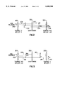
- FIG. 2 is a side view of an optical system in accordance with an example embodiment of the invention.
- FIG. 3 is a side view of an optical system having a alternative arrangement of the components of FIG. 2.
- the light is treated as a transverse electromagnetic wave with a rapidly varying succession of different polarization states.
- the electric field vector may be modeled as rotating around the direction of propagation and changing magnitude, tracing out an ellipse in a fixed space perpendicular to the direction of propagation.
- Special cases of the elliptical model result in tracing out a straight line (linear polarized or plane polarized) or tracing out an ellipse (circular polarized).
- the two orthogonal linear polarization states will be referred to as "s” and "p” and the two orthogonal circular polarization states will be referred to as RHC (right-hand-circular) and LHC (left-hand-circular).
- the states are ordered in quarter-wave increments as follows: s - RHC - p - LHC, and repeating.
- Ideal polarizing filters transmit one polarization state and block the orthogonal state.
- filters and other optical elements will be described as transmitting one polarization state and reflecting the orthogonal state but in general, there are no ideal elements transmitting or reflecting a single state. Instead, in general, the optical elements have some degree of asymmetry in that one polarization state is transmitted more than the orthogonal state or one polarization state is reflected more than the orthogonal state.
- one element is described as a quarter-wave plate.
- An ideal quarter-wave plate retards light by a fixed linear retardation, which for light at a particular wavelength will correspond to a retardation of phase by 90 degrees. In a system with light over a broad spectrum, a quarter-wave plate retards the phase of one wavelength within the light spectrum by 90 degrees and other wavelengths are phase retarded slightly more or less than 90 degrees, depending on wavelength.
- FIG. 2 illustrates a first example embodiment of the invention.
- Element 200 transmits p-polarized light and reflects s-polarized light.
- Element 202 is a quarter-wave plate, converting p-polarized light to LHC polarized light and so forth in the order discussed above.
- Element 204 transmits RHC polarized light and reflects LHC polarized light.
- Non-polarized light 206 enters the system.
- Element 200 partially polarizes the light by transmitting p-polarized light 208.
- Quarter-wave plate 202 phase shifts the p-polarized light to LHC polarized light 210.
- the LHC polarized light 210 is reflected from element 204 which transmits RHC polarized light and reflects LHC polarized light.
- Quarter-wave plate 102 phase shifts the LHC polarized light to s-polarized light 212.
- the s-polarized light 212 is reflected from element 200 which transmits p-polarized light and reflects s-polarized light.
- Quarter-wave plate 202 phase shifts the s-polarized light 212 to RHC polarized light 214.
- Element 204 transmits the RHC polarized light (output 116).
- Light rays 208, 210, 212 and 214 are shown as displaced for simplicity of illustration but they are actually all coplanar.
- light rays 208, 210, 212 and 214 in FIG. 2 are coplanar when viewed as in FIG. 2 but are not coincident when viewed orthogonally as in FIG. 1B.
- Elements 200, 202 and 204 are illustrated as separated for simplicity of illustration but elements 200 and 202 could be combined as a single sandwiched assembly or elements 202 and 204 could be combined as a single sandwiched assembly.
- FIG. 3 illustrates an embodiment with elements 204 and 200 in reversed.
- element 200 was described as transmitting p-polarized light and reflecting s-polarized light.
- Element 200 can be configured for an opposite effect by rotating the element 90 degrees (with the light path through the center of the element being the axis of rotation). Accordingly, in FIG. 3, element 200 transmits s-polarized light and reflects p-polarized light.
- non-polarized light enters element 204 where only RHC-polarized light 308 is transmitted.
- the RHC-polarized light 308 is phase shifted by quarter-wave plate 202 exiting as p-polarized light 310.
- the p-polarized light 310 is reflected by element 200 which reflects p-polarized light and transmits s-polarized light. Reflected p-polarized light 310 is phase shifted by quarter-wave plate 202 exiting as LHC-polarized light 312. The LHC-polarized light 312 is reflected by element 204. Reflected LHC-polarized light 312 is phase shifted by quarter-wave plate 202, exiting as s-polarized light 314. The s-polarized light 314 is transmitted by element 200 so that s-polarized light 316 exits the system. Light rays 308, 310, 312 and 314 are shown as displaced for simplicity of illustration but they are actually all coplanar.
- An example material suitable for element 200 is commercially available as 3M DBEF (Dual Brightness Enhancement Film) from Minnesota Mining and Manufacturing Company (3M).
- An example material suitable for element 204 is commercially available as the Cholesteric Polarizer from Merck Japan Limited.
Abstract
Description
Claims (7)
Priority Applications (1)
| Application Number | Priority Date | Filing Date | Title |
|---|---|---|---|
| US09/026,069 US6080980A (en) | 1998-02-18 | 1998-02-18 | Optics for reducing one dimension of a folded optical path |
Applications Claiming Priority (1)
| Application Number | Priority Date | Filing Date | Title |
|---|---|---|---|
| US09/026,069 US6080980A (en) | 1998-02-18 | 1998-02-18 | Optics for reducing one dimension of a folded optical path |
Publications (1)
| Publication Number | Publication Date |
|---|---|
| US6080980A true US6080980A (en) | 2000-06-27 |
Family
ID=21829713
Family Applications (1)
| Application Number | Title | Priority Date | Filing Date |
|---|---|---|---|
| US09/026,069 Expired - Fee Related US6080980A (en) | 1998-02-18 | 1998-02-18 | Optics for reducing one dimension of a folded optical path |
Country Status (1)
| Country | Link |
|---|---|
| US (1) | US6080980A (en) |
Cited By (7)
| Publication number | Priority date | Publication date | Assignee | Title |
|---|---|---|---|---|
| US6362920B1 (en) * | 2001-01-05 | 2002-03-26 | Intel Corporation | Enhancing the output of a polarized light source using birefringent materials |
| WO2002063373A2 (en) * | 2000-12-29 | 2002-08-15 | Honeywell International Inc. | Beam folding with polarizing splitters |
| US20040062024A1 (en) * | 2002-02-28 | 2004-04-01 | O'connor Michael | Polarization conversion system |
| US20040113045A1 (en) * | 2002-12-13 | 2004-06-17 | Tecu Kirk S. | Apparatus and method for capturing oversize images for imaging devices |
| US20070019274A1 (en) * | 2005-07-25 | 2007-01-25 | Scott Lerner | Double pass light modulator |
| US20090127341A1 (en) * | 2007-11-19 | 2009-05-21 | Xiangyang Feng | Bar-code reading tool |
| CN107065180A (en) * | 2017-01-17 | 2017-08-18 | 浙江唯见科技有限公司 | A kind of close-coupled virtual reality near-eye display system and wear display device |
Citations (7)
| Publication number | Priority date | Publication date | Assignee | Title |
|---|---|---|---|---|
| US5610765A (en) * | 1994-10-17 | 1997-03-11 | The University Of North Carolina At Chapel Hill | Optical path extender for compact imaging display systems |
| US5731886A (en) * | 1995-09-28 | 1998-03-24 | Rockwell International Corporation | Birefringent compensator for reflective polarizers |
| US5751480A (en) * | 1991-04-09 | 1998-05-12 | Canon Kabushiki Kaisha | Plate-like polarizing element, a polarizing conversion unit provided with the element, and a projector provided with the unit |
| US5882774A (en) * | 1993-12-21 | 1999-03-16 | Minnesota Mining And Manufacturing Company | Optical film |
| US5900976A (en) * | 1998-02-20 | 1999-05-04 | Displaytech, Inc. | Display system including a polarizing beam splitter |
| US5900977A (en) * | 1995-06-29 | 1999-05-04 | U.S. Philips Corporation | Polarizing element including layer having alternating areas of birefringent and isotropic materials |
| US5940149A (en) * | 1997-12-11 | 1999-08-17 | Minnesota Mining And Manufacturing Company | Planar polarizer for LCD projectors |
-
1998
- 1998-02-18 US US09/026,069 patent/US6080980A/en not_active Expired - Fee Related
Patent Citations (7)
| Publication number | Priority date | Publication date | Assignee | Title |
|---|---|---|---|---|
| US5751480A (en) * | 1991-04-09 | 1998-05-12 | Canon Kabushiki Kaisha | Plate-like polarizing element, a polarizing conversion unit provided with the element, and a projector provided with the unit |
| US5882774A (en) * | 1993-12-21 | 1999-03-16 | Minnesota Mining And Manufacturing Company | Optical film |
| US5610765A (en) * | 1994-10-17 | 1997-03-11 | The University Of North Carolina At Chapel Hill | Optical path extender for compact imaging display systems |
| US5900977A (en) * | 1995-06-29 | 1999-05-04 | U.S. Philips Corporation | Polarizing element including layer having alternating areas of birefringent and isotropic materials |
| US5731886A (en) * | 1995-09-28 | 1998-03-24 | Rockwell International Corporation | Birefringent compensator for reflective polarizers |
| US5940149A (en) * | 1997-12-11 | 1999-08-17 | Minnesota Mining And Manufacturing Company | Planar polarizer for LCD projectors |
| US5900976A (en) * | 1998-02-20 | 1999-05-04 | Displaytech, Inc. | Display system including a polarizing beam splitter |
Cited By (14)
| Publication number | Priority date | Publication date | Assignee | Title |
|---|---|---|---|---|
| WO2002063373A2 (en) * | 2000-12-29 | 2002-08-15 | Honeywell International Inc. | Beam folding with polarizing splitters |
| US6597504B2 (en) | 2000-12-29 | 2003-07-22 | Honeywell International Inc. | Optical devices employing beam folding with polarizing splitters |
| WO2002063373A3 (en) * | 2000-12-29 | 2003-12-31 | Honeywell Int Inc | Beam folding with polarizing splitters |
| US6362920B1 (en) * | 2001-01-05 | 2002-03-26 | Intel Corporation | Enhancing the output of a polarized light source using birefringent materials |
| US6811272B2 (en) * | 2002-02-28 | 2004-11-02 | Intel Corporation | Polarization conversion system |
| US20040062024A1 (en) * | 2002-02-28 | 2004-04-01 | O'connor Michael | Polarization conversion system |
| US20050254225A1 (en) * | 2002-02-28 | 2005-11-17 | O'connor Michael | Polarization conversion system |
| US7018058B2 (en) * | 2002-02-28 | 2006-03-28 | Intel Corporation | Polarization conversion system |
| US20040113045A1 (en) * | 2002-12-13 | 2004-06-17 | Tecu Kirk S. | Apparatus and method for capturing oversize images for imaging devices |
| US7012234B2 (en) | 2002-12-13 | 2006-03-14 | Hewlett-Packard Development Company, L.P. | Apparatus and method for capturing oversize images for imaging devices |
| US20070019274A1 (en) * | 2005-07-25 | 2007-01-25 | Scott Lerner | Double pass light modulator |
| WO2007014112A1 (en) * | 2005-07-25 | 2007-02-01 | Hewlett-Packard Development Company, L.P. | Double pass light modulator |
| US20090127341A1 (en) * | 2007-11-19 | 2009-05-21 | Xiangyang Feng | Bar-code reading tool |
| CN107065180A (en) * | 2017-01-17 | 2017-08-18 | 浙江唯见科技有限公司 | A kind of close-coupled virtual reality near-eye display system and wear display device |
Similar Documents
| Publication | Publication Date | Title |
|---|---|---|
| KR100951213B1 (en) | Image display unit | |
| JP4408159B2 (en) | Optical imaging device | |
| US6023373A (en) | Reflective image display apparatus | |
| US6816309B2 (en) | Compensated color management systems and methods | |
| US6927912B2 (en) | Optical devices employing beam folding with polarizing splitters | |
| WO2005054906B1 (en) | Improved collimating optical member for real world simulation | |
| CN110908111A (en) | Head-mounted display and optical device thereof | |
| WO2011106567A2 (en) | Waveplate compensation in projection polarization conversion system | |
| CN110967831A (en) | Optical imaging system and head-mounted display equipment | |
| AU2019372438A1 (en) | Compact polarization-based multi-pass optical architectures | |
| US6080980A (en) | Optics for reducing one dimension of a folded optical path | |
| JP2007531909A (en) | Projection system using scanning device | |
| US5377036A (en) | Suppression of stray light reflections in a raster output scanner (ROS) using an overfilled polygon design | |
| US6671094B2 (en) | Composite birefringent crystal and filter | |
| US5440424A (en) | Prism optical device and polarizing optical device | |
| EP1255133B1 (en) | Optical device for rotating the polarization of linearly polarized light | |
| TWM576260U (en) | Head mounted display and optical device thereof | |
| EP2758827B1 (en) | Broadband polarization switching | |
| JP2000249984A (en) | Optical system using reflection and transmission polarizer | |
| JPH04267203A (en) | Polarization converting element | |
| Baur | A new type of beam-splitting polarizer cube | |
| JPH03221917A (en) | Image display device | |
| US20130094087A1 (en) | Tunable filter using a wave plate | |
| JPH0777699A (en) | Polarization controller | |
| JP2761141B2 (en) | Polarization rotating mirror |
Legal Events
| Date | Code | Title | Description |
|---|---|---|---|
| AS | Assignment |
Owner name: HEWLETT-PACKARD COMPANY, CALIFORNIA Free format text: ASSIGNMENT OF ASSIGNORS INTEREST;ASSIGNOR:STEINLE, MICHAEL J.;REEL/FRAME:009184/0509 Effective date: 19980320 |
|
| AS | Assignment |
Owner name: HEWLETT-PACKARD COMPANY, COLORADO Free format text: MERGER;ASSIGNOR:HEWLETT-PACKARD COMPANY;REEL/FRAME:011523/0469 Effective date: 19980520 |
|
| FEPP | Fee payment procedure |
Free format text: PAYOR NUMBER ASSIGNED (ORIGINAL EVENT CODE: ASPN); ENTITY STATUS OF PATENT OWNER: LARGE ENTITY |
|
| FPAY | Fee payment |
Year of fee payment: 4 |
|
| FPAY | Fee payment |
Year of fee payment: 8 |
|
| REMI | Maintenance fee reminder mailed | ||
| REMI | Maintenance fee reminder mailed | ||
| LAPS | Lapse for failure to pay maintenance fees | ||
| STCH | Information on status: patent discontinuation |
Free format text: PATENT EXPIRED DUE TO NONPAYMENT OF MAINTENANCE FEES UNDER 37 CFR 1.362 |
|
| FP | Lapsed due to failure to pay maintenance fee |
Effective date: 20120627 |