EP2758658B1 - Schott einer windturbinenschaufel - Google Patents
Schott einer windturbinenschaufel Download PDFInfo
- Publication number
- EP2758658B1 EP2758658B1 EP12761902.1A EP12761902A EP2758658B1 EP 2758658 B1 EP2758658 B1 EP 2758658B1 EP 12761902 A EP12761902 A EP 12761902A EP 2758658 B1 EP2758658 B1 EP 2758658B1
- Authority
- EP
- European Patent Office
- Prior art keywords
- bulkhead
- rotor blade
- rotor
- rotor hub
- hub
- Prior art date
- Legal status (The legal status is an assumption and is not a legal conclusion. Google has not performed a legal analysis and makes no representation as to the accuracy of the status listed.)
- Revoked
Links
Images


Classifications
-
- F—MECHANICAL ENGINEERING; LIGHTING; HEATING; WEAPONS; BLASTING
- F03—MACHINES OR ENGINES FOR LIQUIDS; WIND, SPRING, OR WEIGHT MOTORS; PRODUCING MECHANICAL POWER OR A REACTIVE PROPULSIVE THRUST, NOT OTHERWISE PROVIDED FOR
- F03D—WIND MOTORS
- F03D1/00—Wind motors with rotation axis substantially parallel to the air flow entering the rotor
- F03D1/06—Rotors
- F03D1/065—Rotors characterised by their construction elements
- F03D1/0675—Rotors characterised by their construction elements of the blades
-
- F—MECHANICAL ENGINEERING; LIGHTING; HEATING; WEAPONS; BLASTING
- F03—MACHINES OR ENGINES FOR LIQUIDS; WIND, SPRING, OR WEIGHT MOTORS; PRODUCING MECHANICAL POWER OR A REACTIVE PROPULSIVE THRUST, NOT OTHERWISE PROVIDED FOR
- F03D—WIND MOTORS
- F03D80/00—Details, components or accessories not provided for in groups F03D1/00 - F03D17/00
-
- F—MECHANICAL ENGINEERING; LIGHTING; HEATING; WEAPONS; BLASTING
- F03—MACHINES OR ENGINES FOR LIQUIDS; WIND, SPRING, OR WEIGHT MOTORS; PRODUCING MECHANICAL POWER OR A REACTIVE PROPULSIVE THRUST, NOT OTHERWISE PROVIDED FOR
- F03D—WIND MOTORS
- F03D1/00—Wind motors with rotation axis substantially parallel to the air flow entering the rotor
- F03D1/06—Rotors
- F03D1/065—Rotors characterised by their construction elements
- F03D1/0691—Rotors characterised by their construction elements of the hub
-
- F—MECHANICAL ENGINEERING; LIGHTING; HEATING; WEAPONS; BLASTING
- F05—INDEXING SCHEMES RELATING TO ENGINES OR PUMPS IN VARIOUS SUBCLASSES OF CLASSES F01-F04
- F05C—INDEXING SCHEME RELATING TO MATERIALS, MATERIAL PROPERTIES OR MATERIAL CHARACTERISTICS FOR MACHINES, ENGINES OR PUMPS OTHER THAN NON-POSITIVE-DISPLACEMENT MACHINES OR ENGINES
- F05C2253/00—Other material characteristics; Treatment of material
- F05C2253/04—Composite, e.g. fibre-reinforced
-
- Y—GENERAL TAGGING OF NEW TECHNOLOGICAL DEVELOPMENTS; GENERAL TAGGING OF CROSS-SECTIONAL TECHNOLOGIES SPANNING OVER SEVERAL SECTIONS OF THE IPC; TECHNICAL SUBJECTS COVERED BY FORMER USPC CROSS-REFERENCE ART COLLECTIONS [XRACs] AND DIGESTS
- Y02—TECHNOLOGIES OR APPLICATIONS FOR MITIGATION OR ADAPTATION AGAINST CLIMATE CHANGE
- Y02E—REDUCTION OF GREENHOUSE GAS [GHG] EMISSIONS, RELATED TO ENERGY GENERATION, TRANSMISSION OR DISTRIBUTION
- Y02E10/00—Energy generation through renewable energy sources
- Y02E10/70—Wind energy
- Y02E10/72—Wind turbines with rotation axis in wind direction
-
- Y—GENERAL TAGGING OF NEW TECHNOLOGICAL DEVELOPMENTS; GENERAL TAGGING OF CROSS-SECTIONAL TECHNOLOGIES SPANNING OVER SEVERAL SECTIONS OF THE IPC; TECHNICAL SUBJECTS COVERED BY FORMER USPC CROSS-REFERENCE ART COLLECTIONS [XRACs] AND DIGESTS
- Y02—TECHNOLOGIES OR APPLICATIONS FOR MITIGATION OR ADAPTATION AGAINST CLIMATE CHANGE
- Y02P—CLIMATE CHANGE MITIGATION TECHNOLOGIES IN THE PRODUCTION OR PROCESSING OF GOODS
- Y02P70/00—Climate change mitigation technologies in the production process for final industrial or consumer products
- Y02P70/50—Manufacturing or production processes characterised by the final manufactured product
Definitions
- the invention relates to a bulkhead of a wind energy plant for arrangement at or in the vicinity of a connection region of a rotor blade to a rotor hub.
- the invention further relates to an arrangement of a bulkhead of a wind turbine.
- the invention also relates to a rotor blade and a rotor hub.
- terminating platforms which in the area of a rotor blade connection, i. the mounting portion of a rotor blade to a rotor hub, usually on the side of the rotor blade, are provided.
- Such termination platforms are usually plates made of metal or composite materials, which on the one hand separate the respective cavities of the rotor blade and the rotor hub from each other and can serve as a standing platform when working on the rotor blade connection.
- Known terminal platforms are often equipped with closable openings or hatches to provide access to the interior of the rotor blade from the rotor hub to allow.
- angular fixings for the terminal platform are known, which are screwed and / or glued to the terminal platform on the one hand and the rotor blade on the other hand.
- the compounds are optionally carried out with additional damping elements to absorb relative movements or vibrations.
- US Pat. No. 7,922,454 B1 discloses a blade segment of a rotor blade made of multiple blade segments.
- a web can be arranged between two opposite straps.
- a protruding from the one sheet member element is provided and the other sheet part hereby corresponding counter-mold.
- WO 2009/085041 A1 discloses a bulkhead disposed proximate a rotor blade root.
- the bulkhead 304 in this case is connected to a flexible flange and allows the movement of the rotor blade root towards or away from the bulkhead.
- the object of the present invention is to provide a bulkhead of a wind turbine, which is structurally simple and requires little time during assembly.
- a bulkhead of a wind energy plant for arrangement at or in the vicinity of a connection region of a rotor blade, in particular a rotor blade root, to a rotor hub, wherein the bulkhead has a cover plate and a suspension device for attachment to the rotor blade or on the rotor hub, wherein the end cap and the suspension device are made in a fiber-laminate construction.
- the bulkhead according to the invention is arranged either on the rotor blade side or on the rotor hub side of the connection region.
- the bulkhead may be attached to or at the vicinity of the connection region either on the rotor blade or on the rotor hub or be.
- the number of connections to be made between the bulkhead and the rotor blade or the rotor hub is halved compared to the prior art, because suitable fasteners do not need to be connected to the end cover, but only an attachment of the suspension takes place on the rotor blade or the rotor hub.
- the number of items required for the assembly for example, mounting bracket, screws and nuts or damping elements, advantageously reduced and the assembly costs, for example, for the production of holes, reduced.
- fiber-laminate-type bulkhead makes it possible in a particularly simple way to produce a single component which unites the end cover and the suspension device in one.
- fiber laminate components are relatively lightweight, which in turn simplifies the assembly of the bulkhead.
- the fiber-laminate construction also allows the production of components with sections of very different properties.
- rigid, flat sections for example for the end covers, can be combined with flexible, tensile-loadable sections for the suspension device in one component.
- a bulkhead is made possible, which is self-springing, so that additional damping elements are saved.
- the combination in a component is particularly simple by the production in one, in particular one piece allows.
- the bulkhead is preferably arranged at or in the vicinity of a connection region of a rotor blade, in particular a rotor blade root, on a rotor hub.
- the rotor blade or the rotor blade root and the rotor hub are generally round, so that in particular a round or substantially round and thus structurally particularly simple form is made possible for the bulkhead.
- This also allows a rotationally symmetrical design of the bulkhead, so that when mounting the bulkhead only low demands on mounting tolerances in a tangential direction, ie against a rotation of the bulkhead in the rotor blade or in the rotor hub, are provided.
- a rotor blade at its near-the-hub region in particular at the rotor blade root, is generally reinforced. There occur therefore less vibrations, deformations and relative movements that would have to be absorbed by the bulkhead or its attachment. This further simplifies the construction of the bulkhead, in particular the suspension device.
- the bulkhead comprises a laminate with glass fiber reinforced plastic.
- Such laminates are easy to process, offer a favorable ratio of weight and stability and are inexpensive.
- the suspension device is designed as a circumferential, in particular continuous, laminate angle. This results in particular the additional advantage that the bulkhead with the entire circumference of the rotor blade or on the rotor hub can rest, whereby a separate seal between bulkhead and rotor blade or rotor hub saved and the assembly of the bulkhead is further simplified.
- the suspension device has a contact surface for fastening the bulkhead, in particular for bonding to the rotor blade or to the rotor hub. This advantageously results in a flat contact between the suspension device and the rotor blade or the rotor hub. This allows in particular a large area and correspondingly stable adhesive bond.
- the contact surface of the suspension device also straight and / or conical.
- large-area contact surfaces for secure connection or bonding of the bulkhead to the rotor blade are provided in a simple manner.
- a straight contact surface essentially describes the shape of a cylinder jacket
- a conical contact surface essentially describes, for example, the shape of a jacket of a truncated cone. There may be provided hybrids thereof.
- a conical contact surface has the particular advantage that smaller manufacturing inaccuracies can be compensated and optimum fitment of the bulkhead is ensured in the rotor blade or the rotor hub. This effect can be further increased by providing on the rotor blade or the rotor hub an essentially complementary shape, in particular also conical, bearing surface for interacting with the contact surface.
- the conical and / or straight configuration of the contact surface is to be understood in particular relative to a longitudinal axis of the rotor blade.
- the bulkhead in particular the end cover, advantageously has at least one, in particular closable, through-opening.
- the access to the interior of the rotor blade is ensured by the rotor hub.
- Shape, location and number of vias are suitably selected according to the circumstances of the case.
- the bulkhead in particular the end cover, has an anti-slip coating on a side facing the connection region
- the bulkhead becomes a particularly secure assembly or maintenance platform, for example for work on a Screw connection or other attachment between the rotor blade and the rotor hub.
- the anti-slip coating includes, for example, bonded sand.
- the bulkhead On a side facing the rotor blade tip, the bulkhead preferably has an impact protection. This prevents the bulkhead from being damaged by falling objects inside the rotor blade, for example loosened resin lumps.
- Suitable impact protection includes, for example, rubber mats or metal plates attached to the bulkhead or end cap.
- the object is also achieved by an arrangement of a bulkhead according to the invention at or in the vicinity of a connection region of a rotor blade, in particular a rotor blade root, to a rotor hub.
- the object is further achieved by a rotor blade with a bulkhead according to the invention.
- the object is also achieved by a rotor hub with a bulkhead according to the invention.
- Fig. 1 shows a schematic representation of a wind turbine 10.
- the wind turbine 10 has a tower 11 and a rotor 12, which includes three rotor blades 14 which are mounted on a rotor hub 9.
- the rotor hub 9 is connected to a rotor shaft, not shown.
- the rotor 12 rotates in a conventional manner. In this way, power can be generated by a generator connected to the rotor 12 or via the rotor hub 9 and the rotor shaft 13 and delivered to a consumer network.
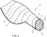
- Fig. 2 shows a lower portion of a rotor blade 14 in a perspective view.
- the rotor blade 14 has on the rotor hub 9 side facing a so-called rotor blade root 16, which is generally round or substantially circular in cross-section.
- the rotor blade 14 itself is hollow inside.
- the rotor blade 14 is formed profiled between the rotor blade root 16 and the rotor blade tip and has a pressure side 18.
- the pressure side 18 is associated with the associated suction side on the opposite side not designated here.
- a bulkhead 22 is arranged in the rotor blade 14, it being possible in one embodiment to glue the bulkhead 22 into the rotor blade root 16.
- the bulkhead 22 is fixedly mounted to the rotor blade root 16 or inserted therein.
- the bulkhead 22 is disposed on the rotor hub 9 or mounted therein, wherein in this embodiment, the transition of the hollow rotor blade 14 to the likewise hollow rotor hub 9 is closed by means of the bulkhead 22 ,
- the bulkhead root 16 is of circular design and has three through-openings 24.
- the through-openings are dimensioned so that a person can rise from the rotor hub into the interior of the rotor blade 14 after opening a hatch at the through-hole 24.
- the bulkhead 22 can be used as a suitable work platform during maintenance work be used on the rotor hub 9 or on the rotor blade 14.
- axis of rotation 26 of the rotor blade 14 is drawn with a dot-dash line, in which the rotor blade 14 is rotatably mounted relative to the rotor hub 9 for adjusting the blade angle, which is also referred to as the pitch angle.
- the axis of rotation intersects the plane of the bulkhead 22, for example in its geometric center M.
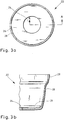
- Fig. 3a shows a schematic plan view of a further embodiment of a bulkhead 22 according to the invention.
- the bulkhead 22 is constructed substantially rotationally symmetrical and has a cover plate 26 in which a round through-opening 24 is provided approximately centrally.
- the access opening 24 can be closed by means of a hatch, not shown.
- the bulkhead 22 comprises a suspension device, which is designed as a circumferential, continuous laminate angle 28.
- a suspension device which is designed as a circumferential, continuous laminate angle 28.
- a plurality of fastening angles which are spaced apart from one another in the radial direction or are separate from one another to be provided as a suspension device.
- Fig. 3b is a sectional view taken along the line AA in Fig. 3a shown.
- the circumferential laminate angle 28 is made in one with the end cover 26 made of a fiber laminate, for example a laminate with glass fiber reinforced plastic.
- the end cover 26 and the peripheral laminate angle 28 form a single, integrated fiber laminate component, wherein the laminate angle 28 has an extent substantially transverse to the surface of the end cover 26.
- the end cap 26 facing away from the edge of the laminate angle 28 is in the in Fig. 3b illustrated embodiment reinforced and has an outwardly directed contact surface 29, by means of which the bulkhead 22 is attached to a rotor blade 14, such as a rotor blade root 16, or a rotor hub 9.
- the contact surface 29 is slightly tapered or conical in order to improve the fit of the bulkhead 22 in the rotor blade 14 and the rotor hub 9.
- the laminate angle 28 is formed relatively thin compared to the end cover 26 and has a certain flexibility. As a result, a damping effect for the bulkhead 22 is effected relative to the rotor blade 14 or the rotor hub 9.
- Fig. 4 shows a schematic and partially enlarged sectional view of an inventive bulkhead 22, which is attached to or in a rotor blade root 16. Shown is the near-nabennhe area of a rotor blade 14 in a sectional view, wherein the rotor blade 14 terminates in a reinforced or stiffened rotor blade root 16.
- the rotor blade root 16 has a substantially round cross section with an outer side 36 and an inner side 37. Not shown are fastening means on the rotor blade root 16 for connection of the rotor blade 14 to the rotor hub. 9
- a bulkhead 22 according to the invention is arranged inside the rotor blade root 16, so that the contact surface 29 of the bulkhead 22 is arranged essentially opposite the inside 37 of the rotor blade root 16. Between the contact surface 29 and the inner side 37 there is an adhesive connection 30, which extends substantially over the entire circumference of the rotor blade root 16 and des Bulkhead 22 extends.
- the inside 37 may have a tapered or conical bearing surface, which is in particular substantially complementary in shape to the contact surface 29, for the contact surface 29 to improve the fit between the bulkhead 22 and the rotor blade 14 and the rotor blade root 16.
- Fig. 4 is also shown that the end cover 26 on the rotor blade root 16 side facing an anti-slip coating 32 has.
- the bulkhead 22 and the end cap 26 of the bulkhead 22 provide a secure and non-slip surface for the assembly or maintenance of the rotor blade 14, the rotor hub 9 or the connection area of the rotor blade 14, in particular the rotor blade root 16, to the rotor hub.
- impact protector 34 are, for example, rubber mats or metal plates, which protect the bulkhead 22 from loose parts in the cavity of the rotor blade 14, for example detached resin lumps.
Landscapes
- Engineering & Computer Science (AREA)
- Life Sciences & Earth Sciences (AREA)
- Sustainable Development (AREA)
- Sustainable Energy (AREA)
- Chemical & Material Sciences (AREA)
- Combustion & Propulsion (AREA)
- Mechanical Engineering (AREA)
- General Engineering & Computer Science (AREA)
- Wind Motors (AREA)
- Woven Fabrics (AREA)
Description
- Die Erfindung betrifft ein Schott einer Windenergieanlage zur Anordnung an oder in der Nähe von einem Anschlussbereich von einem Rotorblatt an einer Rotornabe. Die Erfindung betrifft des Weiteren eine Anordnung eines Schotts einer Windenergieanlage. Die Erfindung betrifft außerdem ein Rotorblatt und eine Rotornabe.
- Im Stand der Technik sind Abschlussplattformen bekannt, die im Bereich eines Rotorblattanschlusses, d.h. des Befestigungsbereichs von einem Rotorblatt an einer Rotornabe, üblicherweise auf Seiten des Rotorblatts, vorgesehen sind. Derartige Abschlussplattformen sind in der Regel Platten aus Metall oder Verbundwerkstoffen, die zum einen die jeweiligen Hohlräume des Rotorblatts und der Rotornabe voneinander trennen und zum anderen als Standplattform bei Arbeiten am Rotorblattanschluss dienen können.
- Bekannte Abschlussplattformen sind oftmals mit verschließbaren Öffnungen oder Luken ausgestattet, um einen Zugang zum Inneren des Rotorblatts von der Rotornabe aus zu ermöglichen.
- Des Weiteren sind winkelförmige Befestigungen für die Abschlussplattform bekannt, die mit der Abschlussplattform einerseits und dem Rotorblatt andererseits verschraubt und/oder verklebt sind. Die Verbindungen sind dabei gegebenenfalls mit zusätzlichen Dämpfungselementen ausgeführt, um Relativbewegungen oder Schwingungen abzufedern.
-
US 7 922 454 B1 offenbart ein Blattsegment eines Rotorblattes, das aus mehreren Blattsegmenten hergestellt ist. Hierbei kann ein Steg zwischen zwei gegenüberliegenden Gurten angeordnet sein. Zum Verbinden zweier Blattteile ist ein aus dem einen Blattteil herausstehendes Element vorgesehen und beim anderen Blattteil eine hiermit korrespondierende Gegenform. -
WO 2009/085041 A1 offenbart ein Schott, das in der Nähe einer Rotorblattwurzel angeordnet ist. Das Schott 304 ist hierbei mit einem flexiblen Flansch verbunden und ermöglicht die Bewegung der Rotorblattwurzel hin oder weg von dem Schott. - Die Aufgabe der vorliegenden Erfindung besteht darin, ein Schott einer Windenergieanlage anzugeben, das konstruktiv einfach ist und bei der Montage wenig Zeitaufwand erfordert.
- Diese Aufgabe wird gelöst durch ein Schott einer Windenergieanlage zur Anordnung an oder in der Nähe von einem Anschlussbereich von einem Rotorblatt, insbesondere einer Rotorblattwurzel, an eine Rotornabe, wobei das Schott einen Abschlussdeckel und eine Aufhängevorrichtung zur Befestigung am Rotorblatt oder an der Rotornabe umfasst, wobei der Abschlussdeckel und die Aufhängevorrichtung in einem in Faser-Laminat-Bauweise gefertigt sind.
- Dabei wird das erfindungsgemäße Schott entweder auf der Rotorblattseite oder auf der Rotornabenseite des Anschlussbereichs angeordnet. Insbesondere kann das Schott am oder in der Nähe vom Anschlussbereich entweder am Rotorblatt oder an der Rotornabe befestigt sein oder werden.
- Durch die Erfindung wird die Anzahl der herzustellenden Verbindungen zwischen dem Schott und dem Rotorblatt bzw. der Rotornabe gegenüber dem Stand der Technik halbiert, weil geeignete Befestigungsmittel nicht erst mit dem Abschlussdeckel verbunden werden müssen, sondern lediglich eine Befestigung der Aufhängevorrichtung an dem Rotorblatt oder der Rotornabe erfolgt. Gleichzeitig wird die Anzahl der zur Montage erforderlichen Einzelteile, beispielsweise Befestigungswinkel, Schrauben und Muttern oder Dämpfungselemente, vorteilhafterweise verringert und der Montageaufwand, beispielsweise für das Herstellen von Bohrungen, reduziert.
- Die Ausführung des Schotts in Faser-Laminat-Bauweise ermöglicht auf besonders einfache Weise die Herstellung eines einzigen Bauteils, das den Abschlussdeckel und die Aufhängevorrichtung in einem vereint. Zudem sind derartige Faser-Laminat-Bauteile relativ leicht, was wiederum die Montage des Schotts vereinfacht.
- Die Faser-Laminat-Bauweise erlaubt zudem die Herstellung von Bauteilen mit abschnittsweise sehr unterschiedlichen Eigenschaften. Insbesondere sind steife, flächige Abschnitte, beispielsweise für die Abschlussdeckel, mit flexiblen, zugbelastbaren Abschnitten für die Aufhängevorrichtung in einem Bauteil kombinierbar. Dadurch wird ein Schott ermöglicht, das selbstfedernd ausgebildet ist, so dass zusätzliche Dämpfungselemente eingespart werden. Die Kombination in einem Bauteil ist besonders einfach durch die Fertigung in einem, insbesondere einem Stück, ermöglicht.
- Bevorzugterweise wird das Schott an oder in der Nähe von einem Anschlussbereich von einem Rotorblatt, insbesondere einer Rotorblattwurzel, an einer Rotornabe angeordnet. In diesem Bereich sind das Rotorblatt bzw. die Rotorblattwurzel und die Rotornabe in der Regel rund ausgebildet, so dass für das Schott insbesondere eine runde oder im Wesentlichen runde und somit konstruktiv besonders einfache Form ermöglicht ist. Hierdurch ist zudem eine rotationssymmetrische Ausbildung des Schotts ermöglicht, so dass bei der Montage des Schotts nur geringe Anforderungen an Montagetoleranzen in tangentialer Richtung, d.h. gegenüber einer Verdrehung des Schotts im Rotorblatt oder in der Rotornabe, gestellt werden.
- Außerdem ist ein Rotorblatt an seinem nabennahen Bereich, insbesondere an der Rotorblattwurzel, in der Regel verstärkt ausgebildet. Dort treten daher weniger Schwingungen, Verformungen und Relativbewegungen auf, die von dem Schott oder dessen Befestigung aufgenommen werden müssten. Dadurch wird die Konstruktion des Schotts, insbesondere der Aufhängevorrichtung, weiter vereinfacht.
- Bevorzugt umfasst das Schott ein Laminat mit glasfaserverstärktem Kunststoff. Derartige Laminate sind einfach zu verarbeiten, bieten ein günstiges Verhältnis von Gewicht und Stabilität und sind kostengünstig.
- Bei einem besonders bevorzugten Schott ist die Aufhängevorrichtung als umlaufender, insbesondere durchgängiger, Laminatwinkel ausgebildet. Hierdurch ergibt sich insbesondere der zusätzliche Vorteil, dass das Schott mit dem gesamten Umfang am Rotorblatt oder an der Rotornabe anliegen kann, wodurch eine separate Abdichtung zwischen Schott und Rotorblatt oder Rotornabe eingespart und die Montage des Schotts weiter vereinfacht wird.
- Besonders vorteilhaft ist es, wenn die Aufhängevorrichtung eine Kontaktfläche zur Befestigung des Schotts, insbesondere zur Verklebung am Rotorblatt oder an der Rotornabe, aufweist. Dadurch ergibt sich vorteilhafterweise ein flächiger Kontakt zwischen der Aufhängevorrichtung und dem Rotorblatt oder der Rotornabe. Dies ermöglicht insbesondere eine großflächige und entsprechend stabile Klebeverbindung.
- Bevorzugterweise ist die Kontaktfläche der Aufhängevorrichtung zudem gerade und/oder konisch ausgebildet. Hierdurch werden auf einfache Weise großflächige Kontaktflächen zur sicheren Verbindung oder Verklebung des Schotts mit dem Rotorblatt bereitgestellt.
- Eine gerade Kontaktfläche beschreibt beispielsweise im Wesentlichen die Form eines Zylindermantels und eine konische Kontaktfläche beschreibt beispielsweise im Wesentlichen die Form eines Mantels eines Kegelstumpfes. Es können Mischformen hiervon vorgesehen sein.
- Eine konische Kontaktfläche hat insbesondere den Vorteil, dass kleinere Fertigungsungenauigkeiten ausgeglichen werden können und eine optimale Einpassung des Schotts in das Rotorblatt oder die Rotornabe gewährleistet ist. Dieser Effekt kann dadurch noch erhöht werden, dass an dem Rotorblatt oder der Rotornabe eine im Wesentlichen formkomplementäre, insbesondere ebenfalls konische, Auflagefläche zum Zusammenwirken mit der Kontaktfläche vorgesehen ist. Die konische und/oder gerade Ausgestaltung der Kontaktfläche ist insbesondere relativ zu einer Längsachse des Rotorblatts zu verstehen.
- Das Schott, insbesondere der Abschlussdeckel, weist vorteilhafterweise wenigstens eine, insbesondere verschließbare, Durchsteigeöffnung auf. Dadurch wird insbesondere der Zugang zum Inneren des Rotorblatts von der Rotornabe aus gewährleistet. Form, Lage und Anzahl der Durchsteigeöffnungen sind dabei entsprechend den Gegebenheiten des Einzelfalls geeignet wählbar.
- Wenn das Schott, insbesondere der Abschlussdeckel, auf einer dem Anschlussbereich zugewandten Seite eine Anti-Rutsch-Beschichtung aufweist, wird das Schott zu einer besonders sicheren Montage- oder Wartungsplattform, beispielsweise für Arbeiten an einer Verschraubung oder sonstigen Befestigung zwischen dem Rotorblatt und der Rotornabe. Die Anti-Rutsch-Beschichtung umfasst beispielsweise gebundenen Sand.
- Auf einer der Rotorblattspitze zugewandten Seite weist das Schott vorzugsweise einen Aufprallschutz auf. Dadurch wird verhindert, dass das Schott durch fallende Gegenstände im Inneren des Rotorblatts, beispielsweise losgelöste Harzklumpen, beschädigt wird. Ein geeigneter Aufprallschutz umfasst beispielsweise Gummimatten oder Metallplatten, die am Schott bzw. am Abschlussdeckel angebracht sind.
- Die Aufgabe wird auch gelöst durch eine Anordnung eines erfindungsgemäßen Schotts an oder in der Nähe von einem Anschlussbereich von einem Rotorblatt, insbesondere einer Rotorblattwurzel, an eine Rotornabe.
- Die Aufgabe wird ferner gelöst durch ein Rotorblatt mit einem erfindungsgemäßen Schott. Die Aufgabe wird außerdem gelöst durch eine Rotornabe mit einem erfindungsgemäßen Schott.
- Weitere Merkmale der Erfindung werden aus der Beschreibung erfindungsgemäßer Ausführungsformen zusammen mit den Ansprüchen und den beigefügten Zeichnungen ersichtlich. Erfindungsgemäße Ausführungsformen können einzelne Merkmale oder eine Kombination mehrerer Merkmale erfüllen.
- Die Erfindung wird nachstehend ohne Beschränkung des allgemeinen Erfindungsgedankens anhand von Ausführungsbeispielen unter Bezugnahme auf die Zeichnungen beschrieben, wobei bezüglich aller im Text nicht näher erläuterten erfindungsgemäßen Einzelheiten ausdrücklich auf die Zeichnungen verwiesen wird. Es zeigen:
- Fig. 1
- schematisch einer Windenergieanlage,
- Fig. 2
- schematisch ein Rotorblatt mit einem erfindungsgemäßen Schott,
- Fig. 3a
- schematisch ein erfindungsgemäßes Schott in Draufsicht sowie
- Fig. 3b
- schematisch eine Schnittdarstellung entlang der Linie A-A in
Fig. 3a und - Fig. 4
- schematisch die Anordnung eines erfindungsgemäßen Schotts an einer Rotorblattwurzel.
- In den Zeichnungen sind jeweils gleiche oder gleichartige Elemente und/oder Teile mit denselben Bezugsziffern versehen, so dass von einer erneuten Vorstellung jeweils abgesehen wird.
-
Fig. 1 zeigt eine schematische Darstellung einer Windenergieanlage 10. Die Windenergieanlage 10 weist einen Turm 11 auf und einen Rotor 12, der drei Rotorblätter 14 umfasst, die auf einer Rotornabe 9 angebracht sind. Die Rotornabe 9 ist mit einer nicht dargestellten Rotorwelle verbunden. Bei Windeinfall dreht sich der Rotor 12 in an sich bekannter Weise. Hierdurch kann Leistung von einem an den Rotor 12 bzw. den über die Rotornabe 9 und die Rotorwelle 13 angeschlossenen Generator erzeugt werden und in ein Verbrauchernetz abgegeben werden. -
Fig. 2 zeigt einen unteren Abschnitt eines Rotorblatts 14 in einer perspektivischen Darstellung. Das Rotorblatt 14 verfügt auf der der Rotornabe 9 zugewandten Seite über eine so genannte Rotorblattwurzel 16, die im Querschnitt im Allgemeinen rund oder im Wesentlichen kreisförmig ausgebildet ist. Das Rotorblatt 14 selbst ist im Inneren hohl. Das Rotorblatt 14 ist zwischen der Rotorblattwurzel 16 und der Rotorblattspitze profiliert ausgebildet und verfügt über eine Druckseite 18. Der Druckseite 18 ist auf der hier nicht bezeichneten gegenüberliegenden Seite die dazugehörige Saugseite zugeordnet. - Die entsprechenden Rotorblattprofile entlang der Längsachse des Rotorblatts 14 laufen an der Hinterkante 20 des Rotorblatts 14 zusammen. Im Bereich der Rotorblattwurzel 16 ist ein Schott 22 in dem Rotorblatt 14 angeordnet, wobei es in einer Ausgestaltung möglich ist, das Schott 22 in die Rotorblattwurzel 16 einzukleben. Das Schott 22 ist fest an der Rotorblattwurzel 16 montiert oder darin eingesetzt.
- In einer alternativen Ausführung der Erfindung, die nicht dargestellt ist, ist das Schott 22 an der Rotornabe 9 angeordnet bzw. montiert oder darin eingesetzt, wobei auch in dieser Ausführungsform der Übergang des hohlen Rotorblatts 14 zur ebenfalls hohlen Rotornabe 9 mittels des Schotts 22 verschlossen ist.
- Das in
Fig. 2 dargestellte Schott 22 ist, wie die Rotorblattwurzel 16, kreisförmig ausgebildet und verfügt über drei Durchsteigeöffnungen 24. Die Durchsteigeöffnungen sind so dimensioniert, dass eine Person nach Öffnung einer Luke an der Durchsteigeöffnung 24 von der Rotornabe in den Innenraum des Rotorblatts 14 steigen kann. - Durch das Schott 22 wird ein Hineinfallen von Gegenständen oder von Personen aus der Rotornabe 9 in das Rotorblatt 14 und umgekehrt verhindert sowie das Rotorblatt 14 gegenüber der Rotornabe 9 bezüglich Schmutz und/oder Feuchtigkeit abgedichtet. Gleichzeitig kann das Schott 22 als entsprechende Arbeitsplattform bei Wartungsarbeiten an der Rotornabe 9 oder am Rotorblatt 14 eingesetzt werden.
- Darüber hinaus ist in
Fig. 2 die Drehachse 26 des Rotorblatts 14 mit einer strich-punktierten Linie eingezeichnet, in die das Rotorblatt 14 relativ zur Rotornabe 9 zur Einstellung des Blattwinkels, der auch als Pitchwinkel bezeichnet wird, drehbar gelagert ist. Die Drehachse schneidet die Ebene des Schotts 22 beispielsweise in dessen geometrischem Mittelpunkt M. -
Fig. 3a zeigt eine schematische Draufsicht auf eine weitere Ausführungsform eines erfindungsgemäßen Schotts 22. Das Schott 22 ist im Wesentlichen rotationssymmetrisch aufgebaut und weist einen Abschlussdeckel 26 auf, in dem etwa mittig eine runde Durchsteigeöffnung 24 vorgesehen ist. Die Durchstiegsöffnung 24 ist mittels einer nicht dargestellten Luke verschließbar. - Ferner umfasst das Schott 22 eine Aufhängevorrichtung, die als umlaufender, durchgängiger Laminatwinkel 28 ausgebildet ist. Alternativ ist im Rahmen der Erfindung auch denkbar, dass mehrere, in radialer Richtung voneinander beabstandete oder voneinander getrennte Befestigungswinkel als Aufhängevorrichtung vorgesehen sind.
- In
Fig. 3b ist eine Schnittdarstellung entlang der Linie A-A inFig. 3a gezeigt. Der umlaufende Laminatwinkel 28 ist in einem mit dem Abschlussdeckel 26 aus einem Faser-Laminat, beispielsweise einem Laminat mit glasfaserverstärktem Kunststoff, gefertigt. Dadurch bilden der Abschlussdeckel 26 und der umlaufende Laminatwinkel 28 ein einzelnes, integriertes Faser-Laminat-Bauteil, wobei der Laminatwinkel 28 eine Ausdehnung im Wesentlichen quer zur Fläche des Abschlussdeckels 26 aufweist. - Der dem Abschlussdeckel 26 abgewandte Rand des Laminatwinkels 28 ist bei dem in
Fig. 3b dargestellten Ausführungsbeispiel verstärkt ausgebildet und weist eine nach außen gerichtete Kontaktfläche 29 auf, mittels der das Schott 22 an einem Rotorblatt 14, beispielsweise einer Rotorblattwurzel 16, oder einer Rotornabe 9 befestigt wird. Die Kontaktfläche 29 ist leicht angeschrägt oder konisch ausgebildet, um die Passung des Schotts 22 in dem Rotorblatt 14 bzw. der Rotornabe 9 zu verbessern. - Der Laminatwinkel 28 ist im Vergleich zum Abschlussdeckel 26 relativ dünn ausgebildet und weist eine gewisse Flexibilität auf. Dadurch wird eine Dämpfungswirkung für das Schott 22 relativ zum Rotorblatt 14 bzw. der Rotornabe 9 bewirkt.
-
Fig. 4 zeigt in einer schematischen und ausschnittsweise vergrößerten Schnittdarstellung ein erfindungsgemäßes Schott 22, das an bzw. in einer Rotorblattwurzel 16 befestigt ist. Gezeigt ist der nabennahe Bereich eines Rotorblatts 14 in einer Schnittdarstellung, wobei das Rotorblatt 14 in einer verstärkten oder versteiften Rotorblattwurzel 16 ausläuft. Die Rotorblattwurzel 16 weist einen im Wesentlichen runden Querschnitt mit einer Außenseite 36 und einer Innenseite 37 auf. Nicht dargestellt sind Befestigungsmittel an der Rotorblattwurzel 16 zum Anschluss von dem Rotorblatt 14 an die Rotornabe 9. - Ein erfindungsgemäßes Schott 22 ist innerhalb der Rotorblattwurzel 16 angeordnet, so dass die Kontaktfläche 29 des Schotts 22 im Wesentlichen gegenüberliegend zu der Innenseite 37 der Rotorblattwurzel 16 angeordnet ist. Zwischen der Kontaktfläche 29 und der Innenseite 37 besteht eine Klebeverbindung 30, die sich im Wesentlichen über den gesamten Umfang der Rotorblattwurzel 16 bzw. des Schotts 22 erstreckt. Die Innenseite 37 kann dabei eine angeschrägte oder konische Auflagefläche, die insbesondere im Wesentlichen formkomplementär zur Kontaktfläche 29 ausgebildet ist, für die Kontaktfläche 29 aufweisen, um die Passform zwischen dem Schott 22 und dem Rotorblatt 14 bzw. der Rotorblattwurzel 16 zu verbessern.
- In
Fig. 4 ist zudem gezeigt, dass der Abschlussdeckel 26 auf der der Rotorblattwurzel 16 zugewandten Seite eine Antirutschbeschichtung 32 aufweist. Somit bietet das Schott 22 bzw. der Abschlussdeckel 26 des Schotts 22 einen sicheren und rutschfesten Untergrund für die Montage oder Wartung des Rotorblatts 14, der Rotornabe 9 oder des Anschlussbereichs von dem Rotorblatt 14, insbesondere der Rotorblattwurzel 16, an die Rotornabe 9. - Die andere Seite des Abschlussdeckels 26, die der Rotorblattspitze und somit dem im Wesentlichen Inneren des Rotorblatts 14 zugewandt ist, ist mit einem Aufprallschutz 34 versehen. Hierbei handelt es sich beispielsweise um Gummimatten oder Metallplatten, die das Schott 22 vor losen Teilen im Hohlraum des Rotorblatts 14, beispielsweise abgelösten Harzklumpen, schützen.
- Alle genannten Merkmale, auch die den Zeichnungen allein zu entnehmenden sowie auch einzelne Merkmale, die in Kombination mit anderen Merkmalen offenbart sind, werden allein und in Kombination als erfindungswesentlich angesehen. Erfindungsgemäße Ausführungsformen können durch einzelne Merkmale oder eine Kombination mehrerer Merkmale erfüllt sein.
-
- 9
- Rotornabe
- 10
- Windenergieanlage
- 11
- Turm
- 12
- Rotor
- 14
- Rotorblatt
- 16
- Rotorblattwurzel
- 18
- Druckseite
- 20
- Hinterkante
- 22
- Schott
- 24
- Durchsteigeöffnung
- 26
- Abschlussdeckel
- 28
- Laminatwinkel
- 29
- Kontaktfläche
- 30
- Klebeverbindung
- 32
- Antirutschbeschichtung
- 34
- Aufprallschutz
- 36
- Außenseite
- 37
- Innenseite
- M
- Mittelpunkt
Claims (11)
- Schott (22) einer Windenergieanlage (10) zur Anordnung an oder in der Nähe von einem Anschlussbereich von einem Rotorblatt (14), an eine Rotornabe (9), wobei das Schott (22) einen Abschlussdeckel (26) und eine Aufhängevorrichtung (28) zur Befestigung am Rotorblatt (14) oder an der Rotornabe (9) umfasst, dadurch gekennzeichnet, dass der Abschlussdeckel (26) und die Aufhängevorrichtung (28) in einem in Faser-Laminat-Bauweise gefertigt sind.
- Schott (22) nach Anspruch 1, dadurch gekennzeichnet, dass das Schott (22) ein Laminat mit glasfaserverstärktem Kunststoff umfasst.
- Schott (22) nach Anspruch 1 oder 2, dadurch gekennzeichnet, dass die Aufhängevorrichtung (28) als umlaufender, insbesondere durchgängiger, Laminatwinkel (28) ausgebildet ist.
- Schott (22) nach einem der Ansprüche 1 bis 3, dadurch gekennzeichnet, dass die Aufhängevorrichtung (28) eine Kontaktfläche (29) zur Befestigung des Schotts (22), insbesondere zur Verklebung am Rotorblatt (14) oder an der Rotornabe (9), aufweist.
- Schott (22) nach Anspruch 4, dadurch gekennzeichnet, dass die Kontaktfläche (29) der Aufhängevorrichtung (28) gerade und/oder konisch ausgebildet ist.
- Schott (22) nach einem der Ansprüche 1 bis 5, dadurch ausgebildet, dass das Schott (22), insbesondere der Abschlussdeckel (26), wenigstens eine, insbesondere verschließbare, Durchsteigeöffnung (24) aufweist.
- Schott (22) nach einem der Ansprüche 1 bis 6, dadurch gekennzeichnet, dass das Schott (22), insbesondere der Abschlussdeckel (26), auf einer dem Anschlussbereich zugewandten Seite eine Anti-Rutsch-Beschichtung (32) aufweist.
- Schott (22) nach einem der Ansprüche 1 bis 7, dadurch gekennzeichnet, dass das Schott (22), insbesondere der Abschlussdeckel (26), auf einer der Rotorblattspitze zugewandten Seite einen Aufprallschutz (34) aufweist.
- Anordnung eines Schotts (22) an oder in der Nähe von einem Anschlussbereich von einem Rotorblatt (14), wobei das Schott (22) nach einem der Ansprüche 1 bis 8 ausgebildet ist.
- Rotorblatt (14) mit einem Schott (22) nach einem der Ansprüche 1 bis 8.
- Rotornabe (9) mit einem Schott (22) nach einem der Ansprüche 1 bis 8.
Applications Claiming Priority (2)
| Application Number | Priority Date | Filing Date | Title |
|---|---|---|---|
| DE102011083152A DE102011083152A1 (de) | 2011-09-21 | 2011-09-21 | Schott einer Windenergieanlage |
| PCT/EP2012/003784 WO2013041190A1 (de) | 2011-09-21 | 2012-09-10 | Schott einer windturbinenschaufel |
Publications (2)
| Publication Number | Publication Date |
|---|---|
| EP2758658A1 EP2758658A1 (de) | 2014-07-30 |
| EP2758658B1 true EP2758658B1 (de) | 2017-12-13 |
Family
ID=46888371
Family Applications (1)
| Application Number | Title | Priority Date | Filing Date |
|---|---|---|---|
| EP12761902.1A Revoked EP2758658B1 (de) | 2011-09-21 | 2012-09-10 | Schott einer windturbinenschaufel |
Country Status (5)
| Country | Link |
|---|---|
| EP (1) | EP2758658B1 (de) |
| DE (1) | DE102011083152A1 (de) |
| DK (1) | DK2758658T3 (de) |
| ES (1) | ES2660498T3 (de) |
| WO (1) | WO2013041190A1 (de) |
Cited By (1)
| Publication number | Priority date | Publication date | Assignee | Title |
|---|---|---|---|---|
| CN109891089A (zh) * | 2016-10-31 | 2019-06-14 | Lm风力发电国际技术有限公司 | 包括隔板的风力涡轮机叶片 |
Families Citing this family (4)
| Publication number | Priority date | Publication date | Assignee | Title |
|---|---|---|---|---|
| EP3447280B1 (de) * | 2017-08-21 | 2020-12-16 | LM Wind Power International Technology II ApS | Trennwandeinheit, windturbinenrotorblatt mit der trennwandeinheit, sowie verfahren zur montage und installation der trennwandeinheit |
| EP4160003A1 (de) * | 2021-09-29 | 2023-04-05 | Siemens Gamesa Renewable Energy A/S | Verfahren zur bereitstellung von zugang zum inneren einer hohlen schaufel einer windturbine, leiterträgeranordnung und windturbine |
| CN114412731A (zh) * | 2022-02-09 | 2022-04-29 | 西安热工研究院有限公司 | 一种风电叶片根部挡板 |
| CN117605628A (zh) * | 2023-10-18 | 2024-02-27 | 中材科技(萍乡)风电叶片有限公司 | 一种风电叶片叶根挡板及制造方法 |
Citations (5)
| Publication number | Priority date | Publication date | Assignee | Title |
|---|---|---|---|---|
| US5062589A (en) | 1989-02-28 | 1991-11-05 | Dornier Luftfahrt Gmbh | Fiber reinforced pressure bulkhead with integrated frame |
| DE202004003521U1 (de) | 2004-03-06 | 2004-06-24 | W2E Wind To Engergy Gmbh | Innenbegehbare Rotornabe |
| US20080179459A1 (en) | 2007-01-30 | 2008-07-31 | Airbus Espana, S.L. | Pressure bulkhead made of composite material for an aircraft |
| WO2009085041A1 (en) | 2007-12-27 | 2009-07-09 | General Electric Company | Flexible wind blade root bulkhead flange |
| EP2497941A1 (de) | 2011-03-08 | 2012-09-12 | LM Wind Power A/S | Windturbinenblatt mit einem Blattwurzelschott |
Family Cites Families (6)
| Publication number | Priority date | Publication date | Assignee | Title |
|---|---|---|---|---|
| DE19950620C1 (de) * | 1999-10-20 | 2001-04-12 | Aloys Wobben | Rotorblatt |
| DE102004023773B3 (de) * | 2004-05-11 | 2005-11-17 | Repower Systems Ag | Windenergieanlage |
| EP1775463A1 (de) * | 2005-10-13 | 2007-04-18 | ECOTECNIA, s.coop. c.l. | Windturbinenblatt |
| DE102006055091A1 (de) * | 2006-11-21 | 2008-05-29 | Repower Systems Ag | Schott einer Windenergieanlage |
| DE102010042530B4 (de) * | 2010-10-15 | 2015-04-30 | Senvion Se | Schott einer Windenergieanlage |
| US7922454B1 (en) * | 2010-10-29 | 2011-04-12 | General Electric Company | Joint design for rotor blade segments of a wind turbine |
-
2011
- 2011-09-21 DE DE102011083152A patent/DE102011083152A1/de not_active Withdrawn
-
2012
- 2012-09-10 DK DK12761902.1T patent/DK2758658T3/en active
- 2012-09-10 WO PCT/EP2012/003784 patent/WO2013041190A1/de not_active Ceased
- 2012-09-10 ES ES12761902.1T patent/ES2660498T3/es active Active
- 2012-09-10 EP EP12761902.1A patent/EP2758658B1/de not_active Revoked
Patent Citations (5)
| Publication number | Priority date | Publication date | Assignee | Title |
|---|---|---|---|---|
| US5062589A (en) | 1989-02-28 | 1991-11-05 | Dornier Luftfahrt Gmbh | Fiber reinforced pressure bulkhead with integrated frame |
| DE202004003521U1 (de) | 2004-03-06 | 2004-06-24 | W2E Wind To Engergy Gmbh | Innenbegehbare Rotornabe |
| US20080179459A1 (en) | 2007-01-30 | 2008-07-31 | Airbus Espana, S.L. | Pressure bulkhead made of composite material for an aircraft |
| WO2009085041A1 (en) | 2007-12-27 | 2009-07-09 | General Electric Company | Flexible wind blade root bulkhead flange |
| EP2497941A1 (de) | 2011-03-08 | 2012-09-12 | LM Wind Power A/S | Windturbinenblatt mit einem Blattwurzelschott |
Non-Patent Citations (4)
| Title |
|---|
| ANONYMOUS: "LM 40.1 P L-Damper Technical blade manual", 9 October 2008 (2008-10-09), pages 1 - 59, XP055520177 |
| ANONYMOUS: "LM Glasfiber Signs Blades Contract with GE Energy in Canada", NETCOMPOSITES, 11 March 2005 (2005-03-11), XP055520180, Retrieved from the Internet <URL:https://netcomposites.com/news/2005/july/29/lm-glasfiber-signs-blades-contract-with-ge-energy-in-canada> |
| ANONYMOUS: "U chequer plate LM 40.1 P", LM TECHNICAL DRAWING, 25 October 2005 (2005-10-25), pages 1 |
| OLE THYBO THOMSEN: "Sandwich Materials for Wind Turbine Blades - Present and Future", JOURNAL OF SANDWICH STRUCTURES AND MATERIALS, vol. 11, no. 7, January 2009 (2009-01-01), pages 7 - 26, XP055520167 |
Cited By (2)
| Publication number | Priority date | Publication date | Assignee | Title |
|---|---|---|---|---|
| CN109891089A (zh) * | 2016-10-31 | 2019-06-14 | Lm风力发电国际技术有限公司 | 包括隔板的风力涡轮机叶片 |
| CN109891089B (zh) * | 2016-10-31 | 2021-02-09 | Lm风力发电国际技术有限公司 | 包括隔板的风力涡轮机叶片 |
Also Published As
| Publication number | Publication date |
|---|---|
| ES2660498T3 (es) | 2018-03-22 |
| DK2758658T3 (en) | 2018-03-19 |
| EP2758658A1 (de) | 2014-07-30 |
| DE102011083152A1 (de) | 2013-03-21 |
| WO2013041190A1 (de) | 2013-03-28 |
Similar Documents
| Publication | Publication Date | Title |
|---|---|---|
| EP2182203B2 (de) | Rotorblatt mit Blattspitzenverlängerung für eine Windenergieanlage | |
| DE102007014861C5 (de) | Verbindung von Bauteilen einer Windenergieanlage | |
| EP1925818B1 (de) | Rotor einer Windenergieanlage mit einem Schott | |
| DE19903550C1 (de) | Blattwurzel für Propeller- und Rotorblätter | |
| EP2035694B1 (de) | Rotornabe einer windenergieanlage | |
| EP3469212B1 (de) | Rotor für eine windenergieanlage, rotorblatt für eine windenergieanlage, hülse und verfahren zur montage eines rotors | |
| EP2788618B1 (de) | Hinterkasten, rotorblatt mit hinterkasten und windenergieanlage mit solchem rotorblatt | |
| EP2366891B1 (de) | Windenergieanlagenrotorblatt | |
| EP0057272B1 (de) | Rotorblatt in Schalenbauweise | |
| DE10324166B4 (de) | Rotorblattanschluss | |
| EP2261113B1 (de) | Propeller | |
| EP3455493B1 (de) | Windenergieanlagen-rotorblatt, und windenergieanlage mit selbigem | |
| DE102011056486A1 (de) | Windkraftanlagenflügel mit modularer Vorderkante | |
| WO2013041190A1 (de) | Schott einer windturbinenschaufel | |
| WO2006039953A1 (de) | Rotorblatt für eine windenergieanlage | |
| DE2648343A1 (de) | Schlag- und schwenkgelenkloser rotor | |
| EP3147498A1 (de) | Rotorblatt, windenergieanlage, verfahren zum herstellen eines rotorblatts und zum aufstellen einer windenergieanlage | |
| EP3559417B1 (de) | Verfahren zum herstellen eines windenergieanlagen-rotorblattes und windenergieanlagen-rotorblatt | |
| DE202013007886U1 (de) | Windenergieanlagenrotorblatt mit passiver Lastreduzierung | |
| WO2017089047A1 (de) | Vertikale windkraftanlage | |
| DE102014106930B4 (de) | Lasttragendes Verkleidungselement für eine Klappenverstellmechanik und Flugzeug mit einem solchen Verkleidungselement | |
| DE102013003634A1 (de) | Windenergieanlagenrotorblatt mit einem Blattanschlussbereich | |
| EP2363602A2 (de) | Windflügel für eine Strömungsenergieanlage | |
| DE102007032937B4 (de) | Schutzvorrichtung zum Schutz eines Blattlagers einer Windenergieanlage | |
| WO2014067020A1 (de) | Rotorblatt für windturbine |
Legal Events
| Date | Code | Title | Description |
|---|---|---|---|
| PUAI | Public reference made under article 153(3) epc to a published international application that has entered the european phase |
Free format text: ORIGINAL CODE: 0009012 |
|
| 17P | Request for examination filed |
Effective date: 20140221 |
|
| AK | Designated contracting states |
Kind code of ref document: A1 Designated state(s): AL AT BE BG CH CY CZ DE DK EE ES FI FR GB GR HR HU IE IS IT LI LT LU LV MC MK MT NL NO PL PT RO RS SE SI SK SM TR |
|
| DAX | Request for extension of the european patent (deleted) | ||
| RAP1 | Party data changed (applicant data changed or rights of an application transferred) |
Owner name: SENVION GMBH |
|
| RIN1 | Information on inventor provided before grant (corrected) |
Inventor name: ZELLER, LENZ SIMON |
|
| RIC1 | Information provided on ipc code assigned before grant |
Ipc: F03D 80/00 20160101ALI20170711BHEP Ipc: F03D 1/06 20060101AFI20170711BHEP |
|
| GRAP | Despatch of communication of intention to grant a patent |
Free format text: ORIGINAL CODE: EPIDOSNIGR1 |
|
| STAA | Information on the status of an ep patent application or granted ep patent |
Free format text: STATUS: GRANT OF PATENT IS INTENDED |
|
| INTG | Intention to grant announced |
Effective date: 20170823 |
|
| GRAS | Grant fee paid |
Free format text: ORIGINAL CODE: EPIDOSNIGR3 |
|
| GRAA | (expected) grant |
Free format text: ORIGINAL CODE: 0009210 |
|
| STAA | Information on the status of an ep patent application or granted ep patent |
Free format text: STATUS: THE PATENT HAS BEEN GRANTED |
|
| AK | Designated contracting states |
Kind code of ref document: B1 Designated state(s): AL AT BE BG CH CY CZ DE DK EE ES FI FR GB GR HR HU IE IS IT LI LT LU LV MC MK MT NL NO PL PT RO RS SE SI SK SM TR |
|
| REG | Reference to a national code |
Ref country code: GB Ref legal event code: FG4D Free format text: NOT ENGLISH |
|
| REG | Reference to a national code |
Ref country code: AT Ref legal event code: REF Ref document number: 954644 Country of ref document: AT Kind code of ref document: T Effective date: 20171215 Ref country code: CH Ref legal event code: EP |
|
| REG | Reference to a national code |
Ref country code: IE Ref legal event code: FG4D Free format text: LANGUAGE OF EP DOCUMENT: GERMAN |
|
| REG | Reference to a national code |
Ref country code: DE Ref legal event code: R096 Ref document number: 502012011827 Country of ref document: DE |
|
| REG | Reference to a national code |
Ref country code: DK Ref legal event code: T3 Effective date: 20180316 |
|
| REG | Reference to a national code |
Ref country code: ES Ref legal event code: FG2A Ref document number: 2660498 Country of ref document: ES Kind code of ref document: T3 Effective date: 20180322 |
|
| REG | Reference to a national code |
Ref country code: NL Ref legal event code: MP Effective date: 20171213 |
|
| REG | Reference to a national code |
Ref country code: LT Ref legal event code: MG4D |
|
| PG25 | Lapsed in a contracting state [announced via postgrant information from national office to epo] |
Ref country code: FI Free format text: LAPSE BECAUSE OF FAILURE TO SUBMIT A TRANSLATION OF THE DESCRIPTION OR TO PAY THE FEE WITHIN THE PRESCRIBED TIME-LIMIT Effective date: 20171213 Ref country code: SE Free format text: LAPSE BECAUSE OF FAILURE TO SUBMIT A TRANSLATION OF THE DESCRIPTION OR TO PAY THE FEE WITHIN THE PRESCRIBED TIME-LIMIT Effective date: 20171213 Ref country code: LT Free format text: LAPSE BECAUSE OF FAILURE TO SUBMIT A TRANSLATION OF THE DESCRIPTION OR TO PAY THE FEE WITHIN THE PRESCRIBED TIME-LIMIT Effective date: 20171213 Ref country code: NO Free format text: LAPSE BECAUSE OF FAILURE TO SUBMIT A TRANSLATION OF THE DESCRIPTION OR TO PAY THE FEE WITHIN THE PRESCRIBED TIME-LIMIT Effective date: 20180313 |
|
| PG25 | Lapsed in a contracting state [announced via postgrant information from national office to epo] |
Ref country code: GR Free format text: LAPSE BECAUSE OF FAILURE TO SUBMIT A TRANSLATION OF THE DESCRIPTION OR TO PAY THE FEE WITHIN THE PRESCRIBED TIME-LIMIT Effective date: 20180314 Ref country code: BG Free format text: LAPSE BECAUSE OF FAILURE TO SUBMIT A TRANSLATION OF THE DESCRIPTION OR TO PAY THE FEE WITHIN THE PRESCRIBED TIME-LIMIT Effective date: 20180313 Ref country code: HR Free format text: LAPSE BECAUSE OF FAILURE TO SUBMIT A TRANSLATION OF THE DESCRIPTION OR TO PAY THE FEE WITHIN THE PRESCRIBED TIME-LIMIT Effective date: 20171213 Ref country code: LV Free format text: LAPSE BECAUSE OF FAILURE TO SUBMIT A TRANSLATION OF THE DESCRIPTION OR TO PAY THE FEE WITHIN THE PRESCRIBED TIME-LIMIT Effective date: 20171213 Ref country code: RS Free format text: LAPSE BECAUSE OF FAILURE TO SUBMIT A TRANSLATION OF THE DESCRIPTION OR TO PAY THE FEE WITHIN THE PRESCRIBED TIME-LIMIT Effective date: 20171213 |
|
| PG25 | Lapsed in a contracting state [announced via postgrant information from national office to epo] |
Ref country code: NL Free format text: LAPSE BECAUSE OF FAILURE TO SUBMIT A TRANSLATION OF THE DESCRIPTION OR TO PAY THE FEE WITHIN THE PRESCRIBED TIME-LIMIT Effective date: 20171213 |
|
| PG25 | Lapsed in a contracting state [announced via postgrant information from national office to epo] |
Ref country code: SK Free format text: LAPSE BECAUSE OF FAILURE TO SUBMIT A TRANSLATION OF THE DESCRIPTION OR TO PAY THE FEE WITHIN THE PRESCRIBED TIME-LIMIT Effective date: 20171213 Ref country code: CY Free format text: LAPSE BECAUSE OF FAILURE TO SUBMIT A TRANSLATION OF THE DESCRIPTION OR TO PAY THE FEE WITHIN THE PRESCRIBED TIME-LIMIT Effective date: 20171213 Ref country code: CZ Free format text: LAPSE BECAUSE OF FAILURE TO SUBMIT A TRANSLATION OF THE DESCRIPTION OR TO PAY THE FEE WITHIN THE PRESCRIBED TIME-LIMIT Effective date: 20171213 Ref country code: EE Free format text: LAPSE BECAUSE OF FAILURE TO SUBMIT A TRANSLATION OF THE DESCRIPTION OR TO PAY THE FEE WITHIN THE PRESCRIBED TIME-LIMIT Effective date: 20171213 |
|
| PG25 | Lapsed in a contracting state [announced via postgrant information from national office to epo] |
Ref country code: SM Free format text: LAPSE BECAUSE OF FAILURE TO SUBMIT A TRANSLATION OF THE DESCRIPTION OR TO PAY THE FEE WITHIN THE PRESCRIBED TIME-LIMIT Effective date: 20171213 Ref country code: PL Free format text: LAPSE BECAUSE OF FAILURE TO SUBMIT A TRANSLATION OF THE DESCRIPTION OR TO PAY THE FEE WITHIN THE PRESCRIBED TIME-LIMIT Effective date: 20171213 Ref country code: IT Free format text: LAPSE BECAUSE OF FAILURE TO SUBMIT A TRANSLATION OF THE DESCRIPTION OR TO PAY THE FEE WITHIN THE PRESCRIBED TIME-LIMIT Effective date: 20171213 Ref country code: RO Free format text: LAPSE BECAUSE OF FAILURE TO SUBMIT A TRANSLATION OF THE DESCRIPTION OR TO PAY THE FEE WITHIN THE PRESCRIBED TIME-LIMIT Effective date: 20171213 Ref country code: IS Free format text: LAPSE BECAUSE OF FAILURE TO SUBMIT A TRANSLATION OF THE DESCRIPTION OR TO PAY THE FEE WITHIN THE PRESCRIBED TIME-LIMIT Effective date: 20180413 |
|
| REG | Reference to a national code |
Ref country code: DE Ref legal event code: R026 Ref document number: 502012011827 Country of ref document: DE |
|
| PLBI | Opposition filed |
Free format text: ORIGINAL CODE: 0009260 |
|
| REG | Reference to a national code |
Ref country code: FR Ref legal event code: PLFP Year of fee payment: 7 |
|
| PG25 | Lapsed in a contracting state [announced via postgrant information from national office to epo] |
Ref country code: MT Free format text: LAPSE BECAUSE OF FAILURE TO SUBMIT A TRANSLATION OF THE DESCRIPTION OR TO PAY THE FEE WITHIN THE PRESCRIBED TIME-LIMIT Effective date: 20171213 |
|
| PLAX | Notice of opposition and request to file observation + time limit sent |
Free format text: ORIGINAL CODE: EPIDOSNOBS2 |
|
| 26 | Opposition filed |
Opponent name: LM WP PATENT HOLDING A/S LM WIND POWER A/S Effective date: 20180913 |
|
| PLBB | Reply of patent proprietor to notice(s) of opposition received |
Free format text: ORIGINAL CODE: EPIDOSNOBS3 |
|
| PG25 | Lapsed in a contracting state [announced via postgrant information from national office to epo] |
Ref country code: SI Free format text: LAPSE BECAUSE OF FAILURE TO SUBMIT A TRANSLATION OF THE DESCRIPTION OR TO PAY THE FEE WITHIN THE PRESCRIBED TIME-LIMIT Effective date: 20171213 |
|
| PG25 | Lapsed in a contracting state [announced via postgrant information from national office to epo] |
Ref country code: MC Free format text: LAPSE BECAUSE OF FAILURE TO SUBMIT A TRANSLATION OF THE DESCRIPTION OR TO PAY THE FEE WITHIN THE PRESCRIBED TIME-LIMIT Effective date: 20171213 |
|
| REG | Reference to a national code |
Ref country code: CH Ref legal event code: PL |
|
| REG | Reference to a national code |
Ref country code: BE Ref legal event code: MM Effective date: 20180930 |
|
| REG | Reference to a national code |
Ref country code: IE Ref legal event code: MM4A |
|
| PG25 | Lapsed in a contracting state [announced via postgrant information from national office to epo] |
Ref country code: LU Free format text: LAPSE BECAUSE OF NON-PAYMENT OF DUE FEES Effective date: 20180910 |
|
| PG25 | Lapsed in a contracting state [announced via postgrant information from national office to epo] |
Ref country code: IE Free format text: LAPSE BECAUSE OF NON-PAYMENT OF DUE FEES Effective date: 20180910 |
|
| PG25 | Lapsed in a contracting state [announced via postgrant information from national office to epo] |
Ref country code: BE Free format text: LAPSE BECAUSE OF NON-PAYMENT OF DUE FEES Effective date: 20180930 Ref country code: CH Free format text: LAPSE BECAUSE OF NON-PAYMENT OF DUE FEES Effective date: 20180930 Ref country code: LI Free format text: LAPSE BECAUSE OF NON-PAYMENT OF DUE FEES Effective date: 20180930 |
|
| REG | Reference to a national code |
Ref country code: AT Ref legal event code: MM01 Ref document number: 954644 Country of ref document: AT Kind code of ref document: T Effective date: 20180910 |
|
| PG25 | Lapsed in a contracting state [announced via postgrant information from national office to epo] |
Ref country code: AT Free format text: LAPSE BECAUSE OF NON-PAYMENT OF DUE FEES Effective date: 20180910 |
|
| PGFP | Annual fee paid to national office [announced via postgrant information from national office to epo] |
Ref country code: DE Payment date: 20190923 Year of fee payment: 8 |
|
| PGFP | Annual fee paid to national office [announced via postgrant information from national office to epo] |
Ref country code: ES Payment date: 20191023 Year of fee payment: 8 |
|
| PG25 | Lapsed in a contracting state [announced via postgrant information from national office to epo] |
Ref country code: TR Free format text: LAPSE BECAUSE OF FAILURE TO SUBMIT A TRANSLATION OF THE DESCRIPTION OR TO PAY THE FEE WITHIN THE PRESCRIBED TIME-LIMIT Effective date: 20171213 |
|
| PG25 | Lapsed in a contracting state [announced via postgrant information from national office to epo] |
Ref country code: PT Free format text: LAPSE BECAUSE OF FAILURE TO SUBMIT A TRANSLATION OF THE DESCRIPTION OR TO PAY THE FEE WITHIN THE PRESCRIBED TIME-LIMIT Effective date: 20171213 Ref country code: HU Free format text: LAPSE BECAUSE OF FAILURE TO SUBMIT A TRANSLATION OF THE DESCRIPTION OR TO PAY THE FEE WITHIN THE PRESCRIBED TIME-LIMIT; INVALID AB INITIO Effective date: 20120910 |
|
| PG25 | Lapsed in a contracting state [announced via postgrant information from national office to epo] |
Ref country code: MK Free format text: LAPSE BECAUSE OF NON-PAYMENT OF DUE FEES Effective date: 20171213 |
|
| PG25 | Lapsed in a contracting state [announced via postgrant information from national office to epo] |
Ref country code: AL Free format text: LAPSE BECAUSE OF FAILURE TO SUBMIT A TRANSLATION OF THE DESCRIPTION OR TO PAY THE FEE WITHIN THE PRESCRIBED TIME-LIMIT Effective date: 20171213 |
|
| RAP2 | Party data changed (patent owner data changed or rights of a patent transferred) |
Owner name: SENVION DEUTSCHLAND GMBH |
|
| PGFP | Annual fee paid to national office [announced via postgrant information from national office to epo] |
Ref country code: GB Payment date: 20200923 Year of fee payment: 9 Ref country code: FR Payment date: 20200921 Year of fee payment: 9 Ref country code: DK Payment date: 20200922 Year of fee payment: 9 |
|
| APAH | Appeal reference modified |
Free format text: ORIGINAL CODE: EPIDOSCREFNO |
|
| APBM | Appeal reference recorded |
Free format text: ORIGINAL CODE: EPIDOSNREFNO |
|
| APBP | Date of receipt of notice of appeal recorded |
Free format text: ORIGINAL CODE: EPIDOSNNOA2O |
|
| APBU | Appeal procedure closed |
Free format text: ORIGINAL CODE: EPIDOSNNOA9O |
|
| REG | Reference to a national code |
Ref country code: DE Ref legal event code: R119 Ref document number: 502012011827 Country of ref document: DE |
|
| PG25 | Lapsed in a contracting state [announced via postgrant information from national office to epo] |
Ref country code: DE Free format text: LAPSE BECAUSE OF NON-PAYMENT OF DUE FEES Effective date: 20210401 |
|
| RDAF | Communication despatched that patent is revoked |
Free format text: ORIGINAL CODE: EPIDOSNREV1 |
|
| REG | Reference to a national code |
Ref country code: DE Ref legal event code: R103 Ref document number: 502012011827 Country of ref document: DE Ref country code: DE Ref legal event code: R064 Ref document number: 502012011827 Country of ref document: DE |
|
| REG | Reference to a national code |
Ref country code: ES Ref legal event code: FD2A Effective date: 20220117 |
|
| RDAG | Patent revoked |
Free format text: ORIGINAL CODE: 0009271 |
|
| STAA | Information on the status of an ep patent application or granted ep patent |
Free format text: STATUS: PATENT REVOKED |
|
| REG | Reference to a national code |
Ref country code: CH Ref legal event code: PL |
|
| REG | Reference to a national code |
Ref country code: FI Ref legal event code: MGE |
|
| 27W | Patent revoked |
Effective date: 20211108 |
|
| GBPR | Gb: patent revoked under art. 102 of the ep convention designating the uk as contracting state |
Effective date: 20211108 |
|
| PG25 | Lapsed in a contracting state [announced via postgrant information from national office to epo] |
Ref country code: ES Free format text: LAPSE BECAUSE OF NON-PAYMENT OF DUE FEES Effective date: 20200911 |
|
| REG | Reference to a national code |
Ref country code: AT Ref legal event code: MA03 Ref document number: 954644 Country of ref document: AT Kind code of ref document: T Effective date: 20211108 |
|
| PG25 | Lapsed in a contracting state [announced via postgrant information from national office to epo] |
Ref country code: DK Free format text: LAPSE BECAUSE OF NON-PAYMENT OF DUE FEES Effective date: 20210930 |
|
| PG25 | Lapsed in a contracting state [announced via postgrant information from national office to epo] |
Ref country code: DK Free format text: LAPSE BECAUSE OF NON-PAYMENT OF DUE FEES Effective date: 20210930 |
|
| PG25 | Lapsed in a contracting state [announced via postgrant information from national office to epo] |
Ref country code: FR Free format text: LAPSE BECAUSE OF NON-PAYMENT OF DUE FEES Effective date: 20210930 |
|
| PG25 | Lapsed in a contracting state [announced via postgrant information from national office to epo] |
Ref country code: GB Free format text: LAPSE BECAUSE OF NON-PAYMENT OF DUE FEES Effective date: 20211009 |