EP2758284B1 - Knieairbag mit einem formgebenden inneren füllschlauch - Google Patents
Knieairbag mit einem formgebenden inneren füllschlauch Download PDFInfo
- Publication number
- EP2758284B1 EP2758284B1 EP12756488.8A EP12756488A EP2758284B1 EP 2758284 B1 EP2758284 B1 EP 2758284B1 EP 12756488 A EP12756488 A EP 12756488A EP 2758284 B1 EP2758284 B1 EP 2758284B1
- Authority
- EP
- European Patent Office
- Prior art keywords
- airbag
- filling hose
- disposed
- knee
- knee airbag
- Prior art date
- Legal status (The legal status is an assumption and is not a legal conclusion. Google has not performed a legal analysis and makes no representation as to the accuracy of the status listed.)
- Active
Links
- 210000003127 knee Anatomy 0.000 title claims description 25
- 238000007493 shaping process Methods 0.000 title 1
- 238000013461 design Methods 0.000 claims description 4
- 230000000149 penetrating effect Effects 0.000 claims 1
- 238000005192 partition Methods 0.000 description 9
- 241000234295 Musa Species 0.000 description 2
- 235000018290 Musa x paradisiaca Nutrition 0.000 description 2
- 238000004519 manufacturing process Methods 0.000 description 2
- 238000005422 blasting Methods 0.000 description 1
- 238000011161 development Methods 0.000 description 1
- 230000018109 developmental process Effects 0.000 description 1
- 238000009826 distribution Methods 0.000 description 1
- 230000006870 function Effects 0.000 description 1
- 238000003780 insertion Methods 0.000 description 1
- 230000037431 insertion Effects 0.000 description 1
- 210000002414 leg Anatomy 0.000 description 1
- 238000000034 method Methods 0.000 description 1
- 230000009993 protective function Effects 0.000 description 1
- 238000013022 venting Methods 0.000 description 1
Images

Classifications
-
- B—PERFORMING OPERATIONS; TRANSPORTING
- B60—VEHICLES IN GENERAL
- B60R—VEHICLES, VEHICLE FITTINGS, OR VEHICLE PARTS, NOT OTHERWISE PROVIDED FOR
- B60R21/00—Arrangements or fittings on vehicles for protecting or preventing injuries to occupants or pedestrians in case of accidents or other traffic risks
- B60R21/02—Occupant safety arrangements or fittings, e.g. crash pads
- B60R21/16—Inflatable occupant restraints or confinements designed to inflate upon impact or impending impact, e.g. air bags
- B60R21/20—Arrangements for storing inflatable members in their non-use or deflated condition; Arrangement or mounting of air bag modules or components
- B60R21/205—Arrangements for storing inflatable members in their non-use or deflated condition; Arrangement or mounting of air bag modules or components in dashboards
- B60R21/206—Arrangements for storing inflatable members in their non-use or deflated condition; Arrangement or mounting of air bag modules or components in dashboards in the lower part of dashboards, e.g. for protecting the knees
-
- B—PERFORMING OPERATIONS; TRANSPORTING
- B60—VEHICLES IN GENERAL
- B60R—VEHICLES, VEHICLE FITTINGS, OR VEHICLE PARTS, NOT OTHERWISE PROVIDED FOR
- B60R21/00—Arrangements or fittings on vehicles for protecting or preventing injuries to occupants or pedestrians in case of accidents or other traffic risks
- B60R21/02—Occupant safety arrangements or fittings, e.g. crash pads
- B60R21/16—Inflatable occupant restraints or confinements designed to inflate upon impact or impending impact, e.g. air bags
- B60R21/23—Inflatable members
- B60R21/231—Inflatable members characterised by their shape, construction or spatial configuration
- B60R21/233—Inflatable members characterised by their shape, construction or spatial configuration comprising a plurality of individual compartments; comprising two or more bag-like members, one within the other
- B60R2021/23308—Inflatable members characterised by their shape, construction or spatial configuration comprising a plurality of individual compartments; comprising two or more bag-like members, one within the other the individual compartments defining the external shape of the bag
-
- B—PERFORMING OPERATIONS; TRANSPORTING
- B60—VEHICLES IN GENERAL
- B60R—VEHICLES, VEHICLE FITTINGS, OR VEHICLE PARTS, NOT OTHERWISE PROVIDED FOR
- B60R21/00—Arrangements or fittings on vehicles for protecting or preventing injuries to occupants or pedestrians in case of accidents or other traffic risks
- B60R21/02—Occupant safety arrangements or fittings, e.g. crash pads
- B60R21/16—Inflatable occupant restraints or confinements designed to inflate upon impact or impending impact, e.g. air bags
- B60R21/26—Inflatable occupant restraints or confinements designed to inflate upon impact or impending impact, e.g. air bags characterised by the inflation fluid source or means to control inflation fluid flow
- B60R21/261—Inflatable occupant restraints or confinements designed to inflate upon impact or impending impact, e.g. air bags characterised by the inflation fluid source or means to control inflation fluid flow with means other than bag structure to diffuse or guide inflation fluid
- B60R2021/2612—Gas guiding means, e.g. ducts
Definitions
- the invention relates to a knee airbag for a motor vehicle, comprising a connected to a gas generator and inflated state along a longitudinal direction from an attachable to a vehicle-fixed part rear end to a free, a vehicle occupant zuwendbaren end extending gas bag, wherein the inflated airbag by in its interior transverse to the longitudinal direction extending dividing walls is divided into a plurality of chambers and in the inflated state assumes a banana-shaped curved shape, the vehicle occupant zuwendbare outer surface is curved with a larger radius than its opposite, the vehicle part zuwendbare surface.
- a knee airbag with the aforementioned features is in the DE 10 2008 060858 A1 described.
- the gas bag in its inflated state assumes a banana-shaped, so that usually arranged in the lower part of the dashboard of a motor vehicle or below it gas bag of the knee airbag in front of the lower leg or knee of the front seated vehicle occupant and after deployed at the top between the knees and the dashboard.
- the inflating of the known gas bag is done by introducing gas into the vehicle side accommodated gas generator adjacent first chamber of the gas bag, from where the gas distributed in the individual chambers of the separating partitions formed overflow into the individual chambers and this unfolds and inflates successively ,
- the known knee airbag initially has the disadvantage that the banana shape of the inflated airbag causes a complicated configuration of the blanks for the airbag and their connection with each other, so that the manufacture of the airbag is correspondingly expensive.
- Another disadvantage is that the gas bag inflates comparatively slowly, because the gas must flow from chamber to chamber over the formed in the intermediate partitions and a limited cross section having overflow.
- the inflation of the known airbag is also unfavorable because a knee airbag usually a certain, both legs or knees of a vehicle occupant having covering width.
- the cover thus also has a width of the gas bag correspondingly long break line, it may come at the beginning of the inflation depending on the folding of the airbag to a not sufficiently well-defined pressurization of the cover with an unregulated rupture of the predetermined breaking line.
- JP 2005 069 625 A It is known that the partitions of a knee airbag are pierced to achieve a specific gas and pressure distribution in the airbag. However, it is deliberately no gas in an inner chamber out.
- the invention is therefore based on the object, a knee airbag with the generic, aforementioned features in such a way that the aforementioned disadvantages are avoided.
- the invention provides in its basic idea that at least one connected to the gas generator in the interior of the gas bag, in the filling tube extending in the longitudinal direction of the airbag and thereby filling the dividing walls is arranged with a banana-shaped shape in the inflated state, in the wall of which at least one outflow opening is arranged in the region of each individual chamber of the airbag.
- the invention has the advantage that due to the arrangement of the banana-shaped filling hose in the interior of the airbag, the inflated inflation hose determines the desired banana shape of the airbag, so that the design of the blanks of the airbag and its manufacture can be kept easier.
- a banana-shaped filling tube is much easier to produce than a corresponding shape of an entire, multi-chamber gas bag. Since the gas is introduced virtually simultaneously into the individual chambers of the airbag when inflating the airbag over the entire chamber detecting filling hose and its outflow openings, the inflation of the airbag takes place much faster, so that the knee airbag its protective function in comparison with the known knee airbag much earlier can fulfill. Finally, at the beginning of the inflation process, inflation hose first inflates a pressure on the cover at a defined point, so that the blasting of the cover takes place along the intended break line and is thus improved.
- the filling hose is connected at its front, the gas generator end facing away from the associated outer wall of the gas bag.
- the filling hose with its front end facing away from the gas generator extends only partially into the chamber of the gas bag which is farthest in the longitudinal direction of the gas bag, wherein the discharge opening of the filling hose assigned to the last or uppermost chamber of the gas bag is also formed by an open design End of the filling hose can be formed.
- the invention is not limited to the arrangement of a single filling hose, much more can be provided in a correspondingly large width having gas bag that two parallel aligned filling hoses are arranged in the interior of the gas bag.
- the arrangement of more than two filling hoses is not excluded.
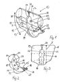
- the filling hose 14 in each of its individual chambers 13 associated portion on opposite discharge ports 22 for the introduced into the filling hose 14 gas, so that the inflowing gas into the filling hose 14 via the outflow openings 22 more or less simultaneously in the individual chambers 13 of the airbag 11 can flow.
- the upper end 23 of the filling hose 14, which is designed to be closed in the illustrated exemplary embodiment, is connected to the associated outer wall 26 of the airbag 11 by means of appropriate fastening straps 24.
- 12 overflow openings 25 are respectively formed at the two outer ends of the partition walls, so that when inflated airbag 11, for example, in a collision of the vehicle occupant pressure equalization between the chambers 13 can perform.
Landscapes
- Engineering & Computer Science (AREA)
- Mechanical Engineering (AREA)
- Air Bags (AREA)
Description
- Die Erfindung betrifft einen Knieairbag für ein Kraftfahrzeug, bestehend aus einem an einen Gasgenerator angeschlossenen und sich in aufgeblasenem Zustand entlang einer Längsrichtung von einem an ein fahrzeugfestes Teil anbindbaren hinteren Ende zu einem freien, einem Fahrzeuginsassen zuwendbaren Ende erstreckenden Gassack, wobei der aufgeblasene Gassack durch in seinem Inneren quer zur Längsrichtung verlaufende Trennwände in mehrere Kammern unterteilt ist und in aufgeblasenem Zustand eine bananenförmig gekrümmte Gestalt einnimmt, deren dem Fahrzeuginsassen zuwendbare äußere Fläche mit einem größeren Radius gekrümmt ist als deren gegenüberliegende, dem Fahrzeugteil zuwendbare Fläche.
- Ein Knieairbag mit den vorgenannten Merkmalen ist in der
DE 10 2008 060858 A1 beschrieben. Bei einem derartigen Knieairbag ist gewünscht, dass der Gassack in seinem aufgeblasenen Zustand eine bananenförmige Gestalt annimmt, damit sich der in der Regel im unteren Bereich des Armaturenbretts eines Kraftfahrzeuges beziehungsweise unterhalb davon angeordnete Gassack des Knieairbags vor die Unterschenkel beziehungsweise Knie des davor sitzenden Fahrzeuginsassen und nach oben hin zwischen den Knien und dem Armaturenbrett entfaltet. Das Aufblasen des bekannten Gassacks geschieht durch Einleiten von Gas in die dem fahrzeugseitig untergebrachten Gasgenerator benachbarte erste Kammer des Gassacks, von wo aus sich das Gas über in den die einzelnen Kammern voneinander trennenden Trennwänden ausgebildete Überströmöffnungen in die einzelnen Kammern verteilt und diese nacheinander entfaltet und aufbläst. - Mit dem bekannten Knieairbag ist zunächst der Nachteil verbunden, dass die Bananenform des aufgeblasenen Gassacks eine komplizierte Ausgestaltung der Zuschnitte für den Gassack und deren Verbindung miteinander bedingt, so dass die Herstellung des Gassacks entsprechend aufwendig ist. Ein weiterer Nachteil besteht darin, dass sich der Gassack vergleichsweise langsam aufbläst, weil das Gas von Kammer zu Kammer über die in den dazwischenliegenden Trennwänden ausgebildeten und einen begrenzten Querschnitt aufweisenden Überströmöffnungen strömen muss. Soweit der aufzublasende Gassack vor seiner Funktion zusammengefaltet hinter einer fahrzeugseitigen und in der Regel an einer Sollbruchlinie zu öffnenden Abdeckung untergebracht ist, ist schließlich das Aufblasverhalten des bekannten Gassackes auch deswegen ungünstig, weil ein Knieairbag in der Regel eine gewisse, beide Beine beziehungsweise Knie eines Fahrzeuginsassen abdeckende Breite aufweist. Soweit die Abdeckung somit ebenfalls eine der Breite des Gassacks entsprechend lange Sollbruchlinie aufweist, kann es zu Beginn des Aufblasvorganges je nach der Einfaltung des Gassackes zu einer nicht ausreichend genau definierten Beaufschlagung der Abdeckung mit einem ungeregelten Aufreißen der Sollbruchlinie kommen.
- Aus
DE 10 2005 047 693 A1 ist ein faltbarer Füllschlauch zur gleichmäßigen Befüllung eines Kopfschutzairbags bekannt. Der Füllschlauch verläuft senkrecht zur Entfaltungsrichtung des Airbags und durchstößt die Trennwände nicht, welche seitlich zum Verlauf des Füllschlauches gebildet sind. - Ferner ist es aus
JP 2005 069 625 A - Der Erfindung liegt daher die Aufgabe zu Grunde, einen Knieairbag mit den gattungsgemäßen, eingangs genannten Merkmale so auszugestalten, dass die vorgenannten Nachteile vermieden sind.
- Die Lösung dieser Aufgabe ergibt sich einschließlich vorteilhafter Ausgestaltungen und Weiterbildungen der Erfindung aus dem Inhalt der Patentansprüche, welche dieser Beschreibung nachgestellt sind.
- Die Erfindung sieht in ihrem Grundgedanken vor, dass im Inneren des Gassacks wenigstens ein an den Gasgenerator angeschlossener, sich in der Längsrichtung des Gassackes erstreckender und dabei die Trennwände durchstoßender Füllschlauch mit einer in aufgeblasenem Zustand bananenförmigen Gestalt angeordnet ist, in dessen Wandung im Bereich jeder einzelnen von ihm erfassten Kammer des Gassackes wenigstens eine Ausströmöffnung angeordnet ist.
- Mit der Erfindung ist der Vorteil verbunden, dass auf Grund der Anordnung des bananenförmigen Füllschlauches im Inneren des Gassacks der aufgeblasene Füllschlauch die gewünschte bananenförmige Gestalt des Gassackes bestimmt, so dass die Auslegung der Zuschnitte des Gassackes und dessen Fertigung einfacher gehalten werden können. Hierbei ist ein bananenförmiger Füllschlauch wesentlich einfacher herzustellen als eine entsprechende Form eines gesamten, mehrere Kammern aufweisenden Gassackes. Da das Gas beim Aufblasen des Gassackes über den alle Kammern erfassenden Füllschlauch und dessen Ausströmöffnungen praktisch gleichzeitig in die einzelnen Kammern des Gassackes eingeleitet wird, vollzieht sich das Aufblasen des Gassackes wesentlich schneller, so dass der Knieairbag seine Schutzfunktion im Vergleich mit dem bekannten Knieairbag wesentlich früher erfüllen kann. Schließlich übt der sich zu Beginn des Aufblasvorganges zuerst aufblasende Füllschlauch an definierter Stelle einen Druck auf die Abdeckung aus, so dass das Aufsprengen der Abdeckung längs der vorgesehenen Sollbruchlinie gerichtet erfolgt und somit verbessert ist.
- Die erfindungsgemäße Anordnung des Füllschlauches gibt auch die Möglichkeit, die einzelnen Kammern des Gassackes unterschiedlich aufzublasen, insbesondere beispielsweise die dem Gasgenerator benachbarte unterste Kammer weniger aufzublasen als die höheren, näher beim Fahrzeuginsassen liegenden Kammern des Gassackes, was bei Einsatz eines aus dem Stand der Technik bekannten Knieairbags ausgeschlossen ist. Hierzu kann vorgesehen sein, dass die den einzelnen Kammern des Gassackes zugeordneten Ausströmöffnungen des Füllschlauches jeweils unterschiedliche Querschnitte aufweisen. Alternativ kann vorgesehen sein, daß in dem den einzelnen Kammern des Gassackes zugeordneten Abschnitten des Füllschlauches jeweils eine unterschiedliche Anzahl von Ausströmöffnungen angeordnet ist. In beiden Fällen kann das Füllverhalten der einzelnen Kammern vom Füllschlauch aus entsprechend eingestellt sein.
- Nach einem Ausführungsbeispiel der Erfindung kann vorgesehen sein, dass der Füllschlauch an seinem vorderen, dem Gasgenerator abgewandten Ende mit der zugeordneten äußeren Wandung des Gassacks verbunden ist.
- Es kann weiterhin vorgesehen sein, dass der Füllschlauch mit seinem vorderen, dem Gasgenerator abgewandten Ende nur teilweise in die in der Längsrichtung des Gassacks entfernteste Kammer des Gassacks hineinreicht, wobei die der letzten beziehungsweise obersten Kammer des Gassacks zugeordnete Ausströmöffnung des Füllschlauches auch durch ein offen ausgebildetes Ende des Füllschlauches gebildet sein kann.
- Die Erfindung ist dabei nicht auf die Anordnung eines einzigen Füllschlauches beschränkt, viel mehr kann bei einem eine entsprechend große Breite aufweisenden Gassack vorgesehen sein, daß im Inneren des Gassacks zwei parallel zueinander ausgerichtete Füllschläuche angeordnet sind. Auch die Anordnung von mehr als zwei Füllschläuchen ist nicht ausgeschlossen.
- Zusätzlich zu der Anordnung des Füllschlauches kann vorgesehen sein, daß in den die Kammer des Gassacks voneinander trennenden Trennwänden jeweils wenigstens eine Überströmöffnung angeordnet ist, wie derartige in den Trennwänden angeordnete Überströmöffnungen aus der gattungsbildenden
DE 10 2008 060858 A1 bekannt sind. Bei der erfindungsgemäßen Ausgestaltung des Knieairbags dienen diese Überströmöffnungen insbesondere einem Druckausgleich zwischen den einzelnen Kammern des Gassackes, insbesondere bei einem Aufprall des Fahrzeuginsassen. - Schließlich kann in an sich bekannter Weise vorgesehen sein, dass in der äußeren Gassackwandung wenigstens eine Ventöffnung zum Ablassen von Gas ins Freie angeordnet ist.
- In der Zeichnung ist ein Ausführungsbeispiel der Erfindung wiedergegeben, welches nachstehend beschrieben ist. Es zeigen:
- Fig. 1
- den aufgeblasenen Gassack eines erfindungsgemäßen Knieairbags in einer Perspektivdarstellung
- Fig. 2
- den Gassack gemäß
Fig. 1 in einer schematisierten Seitenansicht, - Fig. 3
- den Gassack gemäß
Fig. 1 in einer schematisierten Vorderansicht, - Fig. 4
- den im Inneren des Gassackes angeordneten Füllschlauch in einer Einzeldarstellung,
- Fig. 5
- eine die Kammern des Gassackes trennende Trennwand in einer Einzeldarstellung
- Der zunächst in den
Figuren 1 bis 3 insgesamt dargestellte Knieairbag 10 weist einen Gassack 11 auf, der in seiner sich von einem an ein fahrzeugfestes Teil angebundenen hinteren Ende zu einem freien, einem Fahrzeuginsassen zugewandten vorderen Ende erstreckenden Längsrichtung X eine bananenförmig gekrümmte Gestalt aufweist. Der Gassack 11 ist in seinem Inneren durch zwei quer zu seiner Längsrichtung angeordnete Trennwände 12 in drei einzelne Kammern 13 unterteilt. - Im Inneren des Gassackes 11 ist ein zentraler, sich in der Längsrichtung X des Gassackes 11 erstreckender und dabei die Trennwände 12 des Gassackes 11 in darin angeordneten Durchtrittsöffnungen 21 durchstoßender Füllschlauch 14 angeordnet, der entsprechend der Darstellung in
Figur 4 im aufgeblasenen Zustand eine bananenförmige Gestalt hat und aufgrund dieser bananenförmigen Gestalt auch dem Gassack 11 die bananenförmig gekrümmte Gestalt gemäßFigur 1 vermittelt. - Wie sich am Besten aus
Fig. 4 ergibt, weist der Füllschlauch 14 in seinem unteren Bereich 15 eine Aufnahme für einen im Einzelnen nicht dargestellten Gasgenerator auf, wobei in dem Bereich 15 des Füllschlauches 14 eine Öffnung 16 für einen Gasgeneratoranschluss ausgebildet ist. Zusätzlich ist ein Loch 17 zum Hindurchführen eines Haltebolzens für den im Einzelnen nicht dargestellten Gasgenerator angedeutet. InFig. 4 ist weiterhin ausschnittsweise ein entsprechender unterer Abschnitt 18 des Gassackes 11 zusätzlich dargestellt, der den unteren Bereich 15 des Füllschlauches 14 aufnimmt, wobei in diesem unteren Bereich 18 des Gassackes 11 ebenfalls eine Einführöffnung 19 für den Gasgenerator sowie ein Loch 17 zum Durchtritt des Befestigungsbolzens für den Gasgenerator angedeutet sind. In denFiguren 1 und 2 sind ein Gasgeneratoranschluß 27 und ein Steckbolzen 28 angedeutet. - Bei dem dargestellten Ausführungsbeispiel weist der Füllschlauch 14 in jedem seiner den einzelnen Kammern 13 zugeordneten Abschnitt einander gegenüberliegende Ausströmöffnungen 22 für das in den Füllschlauch 14 eingeleitete Gas auf, so daß das in den Füllschlauch 14 einströmende Gas über die Ausströmöffnungen 22 mehr oder weniger gleichzeitig in die einzelnen Kammern 13 des Gassackes 11 einströmen kann. Das bei dem dargestellten Ausführungsbeispiel geschlossen ausgebildete obere Ende 23 des Füllschlauches 14 ist mittels entsprechender Befestigungsbänder 24 mit der zugeordneten äußeren Wandung 26 des Gassackes 11 verbunden.
- Wie sich aus den
Fig. 1 und5 entnehmen lässt, sind jeweils an den beiden äußeren Enden der Trennwände 12 Überströmöffnungen 25 ausgebildet, so daß sich bei aufgeblasenem Gassack 11 beispielsweise bei einem Aufprall des Fahrzeuginsassen ein Druckausgleich zwischen den Kammern 13 vollziehen kann. - Die in der vorstehenden Beschreibung, den Patentansprüchen, der Zusammenfassung und der Zeichnung offenbarten Merkmale des Gegenstandes dieser Unterlagen können einzeln als auch in beliebigen Kombinationen untereinander für die Verwirklichung der Erfindung in ihren verschiedenen Ausführungsformen wesentlich sein.
Claims (8)
- Knieairbag für ein Kraftfahrzeug, bestehend aus einem an einen Gasgenerator angeschlossenen und sich in aufgeblasenem Zustand entlang einer Längsrichtung (X) von einem an ein fahrzeugfestes Teil anbindbaren hinteren Ende zu einem freien, einem Fahrzeuginsassen zuwendbaren Ende erstreckenden Gassack, wobei der aufgeblasene Gassack durch in seinem Inneren quer zur Längsrichtung (X) verlaufende Trennwände in mehrere Kammern unterteilt ist und in aufgeblasenem Zustand eine bananenförmig gekrümmte Gestalt einnimmt, deren dem Fahrzeuginsassen zuwendbare äußere Fläche mit einem größeren Radius gekrümmt ist als deren gegenüberliegende, dem Fahrzeugteil zuwendbare Fläche, dadurch gekennzeichnet, dass im Inneren des Gassacks (11) wenigstens ein an den Gasgenerator angeschlossener, sich in der Längsrichtung(X) des Gassackes (11) erstreckender und dabei die Trennwände (12) durchstoßender Füllschlauch (14) mit einer in aufgeblasenem Zustand bananenförmigen Gestalt angeordnet ist, in dessen Wandung im Bereich jeder einzelnen von ihm erfassten Kammer (13) des Gassackes (11) wenigstens eine Ausströmöffnung angeordnet ist.
- Knieairbag nach Anspruch 1, dadurch gekennzeichnet, dass die den einzelnen Kammern (13) des Gassackes (11) zugeordneten Ausströmöffnungen (22) des Füllschlauches (14) jeweils unterschiedliche Querschnitte aufweisen.
- Knieairbag nach Anspruch 1, dadurch gekennzeichnet, dass in den den einzelnen Kammern (13) des Gassackes (11) zugeordneten Abschnitten des Füllschlauches (14) jeweils eine unterschiedliche Anzahl von Ausströmöffnungen (22) angeordnet ist.
- Knieairbag nach einem der Ansprüche 1 bis 3, dadurch gekennzeichnet, dass der Füllschlauch (14) an seinem vorderen, dem Gasgenerator abgewandten Ende mit der zugeordneten äußeren Wandung des Gassacks (11) verbunden ist.
- Knieairbag nach einem der Ansprüche 1 bis 4, dadurch gekennzeichnet, dass der Füllschlauch (14) mit seinem vorderen, dem Gasgenerator abgewandten Ende nur teilweise in die in der Längsrichtung (X) des Gassacks entfernteste Kammer (13) des Gassacks (11) hineinreicht.
- Knieairbag nach einem der Ansprüche 1 bis 5, dadurch gekennzeichnet, dass bei einem eine große Breite aufweisenden Gassack (11) im Inneren des Gassacks (11) zwei parallel zueinander angeordnete Füllschläuche (14) angeordnet sind.
- Knieairbag nach einem der Ansprüche 1 bis 6, dadurch gekennzeichnet, dass in den die Kammern (13) des Gassacks voneinander trennenden Trennwänden (12) jeweils wenigstens eine Überströmöffnung (25) angeordnet ist.
- Knieairbag nach einem der Ansprüche 1 bis 7, dadurch gekennzeichnet, dass in der äußeren Gassackwandung wenigstens eine Ventöffnung zum Ablassen von Gas ins Freie angeordnet ist.
Applications Claiming Priority (2)
| Application Number | Priority Date | Filing Date | Title |
|---|---|---|---|
| DE102011053863A DE102011053863A1 (de) | 2011-09-22 | 2011-09-22 | Knieairbag mit einem formgebenden inneren Füllschlauch |
| PCT/EP2012/067711 WO2013041406A1 (de) | 2011-09-22 | 2012-09-11 | Knieairbag mit einem formgebenden inneren füllschlauch |
Publications (2)
| Publication Number | Publication Date |
|---|---|
| EP2758284A1 EP2758284A1 (de) | 2014-07-30 |
| EP2758284B1 true EP2758284B1 (de) | 2015-11-04 |
Family
ID=46826529
Family Applications (1)
| Application Number | Title | Priority Date | Filing Date |
|---|---|---|---|
| EP12756488.8A Active EP2758284B1 (de) | 2011-09-22 | 2012-09-11 | Knieairbag mit einem formgebenden inneren füllschlauch |
Country Status (3)
| Country | Link |
|---|---|
| EP (1) | EP2758284B1 (de) |
| DE (1) | DE102011053863A1 (de) |
| WO (1) | WO2013041406A1 (de) |
Families Citing this family (8)
| Publication number | Priority date | Publication date | Assignee | Title |
|---|---|---|---|---|
| JP6446908B2 (ja) * | 2014-08-20 | 2019-01-09 | Joyson Safety Systems Japan株式会社 | 乗員脚部拘束装置 |
| US9475445B2 (en) * | 2014-08-25 | 2016-10-25 | Ford Global Technologies, Llc | Vehicle airbag appendage |
| US9789844B2 (en) | 2015-11-02 | 2017-10-17 | Ford Global Technologies, Llc | Dual chamber airbag with asymmetrically tunable parameters and method of manufacturing the same |
| DE102019208417A1 (de) | 2019-06-11 | 2020-12-17 | Audi Ag | Beinschutzvorrichtung für ein Insassenschutzsystem eines Fahrzeugs |
| JP7812218B2 (ja) * | 2021-11-30 | 2026-02-09 | 株式会社Subaru | ニーエアバッグ装置 |
| CN114407740A (zh) * | 2021-12-15 | 2022-04-29 | 杨旭 | 一种用于新能源汽车智能座舱的高安全性儿童座椅 |
| DE102022100934A1 (de) | 2022-01-17 | 2023-07-20 | Zf Automotive Germany Gmbh | Beingassack, Fahrzeug und Fahrzeugsitz |
| JP7476909B2 (ja) * | 2022-01-24 | 2024-05-01 | トヨタ自動車株式会社 | 車両用助手席エアバッグ装置 |
Family Cites Families (9)
| Publication number | Priority date | Publication date | Assignee | Title |
|---|---|---|---|---|
| JP3912144B2 (ja) * | 2001-05-21 | 2007-05-09 | タカタ株式会社 | 助手席用乗員脚部保護装置 |
| JP3991720B2 (ja) * | 2001-11-29 | 2007-10-17 | タカタ株式会社 | 乗員保護装置 |
| JP2005096625A (ja) * | 2003-09-25 | 2005-04-14 | Toyoda Gosei Co Ltd | 膝保護用エアバッグ装置 |
| JP5053520B2 (ja) * | 2005-04-20 | 2012-10-17 | 日本プラスト株式会社 | エアバッグ |
| DE102005047693B4 (de) * | 2005-09-26 | 2007-11-29 | Takata-Petri Ag | Gassackvorrichtung mit einem aufblasbaren Gassack und einem in dem Gassack angeordneten, faltbaren Füllschlauch |
| DE102008060858B4 (de) | 2008-12-09 | 2012-03-01 | Autoliv Development Ab | Kniegassack |
| JP2009208772A (ja) * | 2009-05-22 | 2009-09-17 | Toyoda Gosei Co Ltd | 膝保護用エアバッグ装置 |
| WO2011010386A1 (ja) * | 2009-07-24 | 2011-01-27 | トヨタ自動車株式会社 | エアバッグ装置 |
| JP5104834B2 (ja) * | 2009-09-10 | 2012-12-19 | トヨタ自動車株式会社 | エアバッグ装置 |
-
2011
- 2011-09-22 DE DE102011053863A patent/DE102011053863A1/de not_active Withdrawn
-
2012
- 2012-09-11 EP EP12756488.8A patent/EP2758284B1/de active Active
- 2012-09-11 WO PCT/EP2012/067711 patent/WO2013041406A1/de not_active Ceased
Also Published As
| Publication number | Publication date |
|---|---|
| WO2013041406A1 (de) | 2013-03-28 |
| EP2758284A1 (de) | 2014-07-30 |
| DE102011053863A1 (de) | 2013-03-28 |
Similar Documents
| Publication | Publication Date | Title |
|---|---|---|
| EP1826073B1 (de) | Knieairbag | |
| DE102008029810B4 (de) | Optimierte Kniegassack-Faltung | |
| EP2424750B1 (de) | Gassackmodul zum schutz des thorax- und kopfbereichs eines fahrzeuginsassen | |
| EP2758284A1 (de) | Knieairbag mit einem formgebenden inneren füllschlauch | |
| EP3194217B1 (de) | Adaptives, entfaltbares rückhalteelement für ein fahrzeugsicherheitssystem, gassackmodul und fahrzeugsicherheitssystem mit einem solchen rückhalteelement sowie verwendung des flossenstrahleffekts in einem adaptiven rückhalteelement | |
| EP2718155B1 (de) | Fahrzeuginsassen-rückhaltesystem mit adaptivem kniegassack | |
| WO2016165815A1 (de) | Frontal-gassack für fahrzeuginsassen sowie gassackmodul | |
| EP2582551B1 (de) | Knieairbaganordnung für fahrzeuge | |
| DE102017131121A1 (de) | Fahrzeuginsassenschutzsystem, Fahrzeugsitz sowie Verfahren zum Entfalten eines Gassacks | |
| DE19930157B4 (de) | Luftsack für ein Kraftfahrzeug | |
| EP1567394A1 (de) | Gassack für eine insassenschutzeinrichtung | |
| DE10235128A1 (de) | Für zwei Personen vorgesehene Airbageinrichtung | |
| DE102009005305B4 (de) | Airbageinrichtung | |
| EP1477372A1 (de) | Sicherheitseinrichtung | |
| EP1531098B1 (de) | Airbag | |
| DE102011117940A1 (de) | Airbageinrichtung für ein Kraftfahrzeug | |
| EP1508485B1 (de) | Airbagmodul | |
| EP3165409B1 (de) | Vorhangairbag-einheit und fahrzeug mit einer derartigen vorhangairbag-einheit | |
| DE102014007035A1 (de) | Kniegassack, Kniegassackmodul und Kniegassackmodul-Anordnung in einem Kraftfahrzeug | |
| DE102015015801B4 (de) | Gassackeinrichtung | |
| EP1816038B1 (de) | Luftsack für ein Kraftfahrzeug | |
| DE102011054053B4 (de) | Airbaganordnung mit einem einen zentralen Gassackbereich und seitlich dazu aufblasbaren Seitengassackbereichen | |
| DE102011117939A1 (de) | Kraftfahrzeugsitz mit einer Seitenairbageinrichtung, Kraftfahrzeug mit einem solchen Kraftfahrzeugsitz und Verfahren zur Steuerung einer Seitenairbageinrichtung eines Kraftfahrzeugsitzes | |
| DE102019203048B4 (de) | Airbagmodul und Kraftfahrzeug | |
| DE102009031118A1 (de) | Sicherheitseinrichtung für ein Kraftfahrzeug |
Legal Events
| Date | Code | Title | Description |
|---|---|---|---|
| PUAI | Public reference made under article 153(3) epc to a published international application that has entered the european phase |
Free format text: ORIGINAL CODE: 0009012 |
|
| 17P | Request for examination filed |
Effective date: 20140129 |
|
| AK | Designated contracting states |
Kind code of ref document: A1 Designated state(s): AL AT BE BG CH CY CZ DE DK EE ES FI FR GB GR HR HU IE IS IT LI LT LU LV MC MK MT NL NO PL PT RO RS SE SI SK SM TR |
|
| DAX | Request for extension of the european patent (deleted) | ||
| GRAP | Despatch of communication of intention to grant a patent |
Free format text: ORIGINAL CODE: EPIDOSNIGR1 |
|
| INTG | Intention to grant announced |
Effective date: 20150415 |
|
| GRAS | Grant fee paid |
Free format text: ORIGINAL CODE: EPIDOSNIGR3 |
|
| GRAA | (expected) grant |
Free format text: ORIGINAL CODE: 0009210 |
|
| AK | Designated contracting states |
Kind code of ref document: B1 Designated state(s): AL AT BE BG CH CY CZ DE DK EE ES FI FR GB GR HR HU IE IS IT LI LT LU LV MC MK MT NL NO PL PT RO RS SE SI SK SM TR |
|
| REG | Reference to a national code |
Ref country code: GB Ref legal event code: FG4D Free format text: NOT ENGLISH |
|
| REG | Reference to a national code |
Ref country code: CH Ref legal event code: EP |
|
| REG | Reference to a national code |
Ref country code: AT Ref legal event code: REF Ref document number: 758946 Country of ref document: AT Kind code of ref document: T Effective date: 20151115 |
|
| REG | Reference to a national code |
Ref country code: IE Ref legal event code: FG4D Free format text: LANGUAGE OF EP DOCUMENT: GERMAN |
|
| REG | Reference to a national code |
Ref country code: DE Ref legal event code: R096 Ref document number: 502012005181 Country of ref document: DE |
|
| REG | Reference to a national code |
Ref country code: NL Ref legal event code: MP Effective date: 20151104 |
|
| REG | Reference to a national code |
Ref country code: LT Ref legal event code: MG4D |
|
| PG25 | Lapsed in a contracting state [announced via postgrant information from national office to epo] |
Ref country code: NL Free format text: LAPSE BECAUSE OF FAILURE TO SUBMIT A TRANSLATION OF THE DESCRIPTION OR TO PAY THE FEE WITHIN THE PRESCRIBED TIME-LIMIT Effective date: 20151104 Ref country code: NO Free format text: LAPSE BECAUSE OF FAILURE TO SUBMIT A TRANSLATION OF THE DESCRIPTION OR TO PAY THE FEE WITHIN THE PRESCRIBED TIME-LIMIT Effective date: 20160204 Ref country code: ES Free format text: LAPSE BECAUSE OF FAILURE TO SUBMIT A TRANSLATION OF THE DESCRIPTION OR TO PAY THE FEE WITHIN THE PRESCRIBED TIME-LIMIT Effective date: 20151104 Ref country code: LT Free format text: LAPSE BECAUSE OF FAILURE TO SUBMIT A TRANSLATION OF THE DESCRIPTION OR TO PAY THE FEE WITHIN THE PRESCRIBED TIME-LIMIT Effective date: 20151104 Ref country code: HR Free format text: LAPSE BECAUSE OF FAILURE TO SUBMIT A TRANSLATION OF THE DESCRIPTION OR TO PAY THE FEE WITHIN THE PRESCRIBED TIME-LIMIT Effective date: 20151104 Ref country code: IS Free format text: LAPSE BECAUSE OF FAILURE TO SUBMIT A TRANSLATION OF THE DESCRIPTION OR TO PAY THE FEE WITHIN THE PRESCRIBED TIME-LIMIT Effective date: 20160304 Ref country code: IT Free format text: LAPSE BECAUSE OF FAILURE TO SUBMIT A TRANSLATION OF THE DESCRIPTION OR TO PAY THE FEE WITHIN THE PRESCRIBED TIME-LIMIT Effective date: 20151104 |
|
| PG25 | Lapsed in a contracting state [announced via postgrant information from national office to epo] |
Ref country code: SE Free format text: LAPSE BECAUSE OF FAILURE TO SUBMIT A TRANSLATION OF THE DESCRIPTION OR TO PAY THE FEE WITHIN THE PRESCRIBED TIME-LIMIT Effective date: 20151104 Ref country code: PT Free format text: LAPSE BECAUSE OF FAILURE TO SUBMIT A TRANSLATION OF THE DESCRIPTION OR TO PAY THE FEE WITHIN THE PRESCRIBED TIME-LIMIT Effective date: 20160304 Ref country code: LV Free format text: LAPSE BECAUSE OF FAILURE TO SUBMIT A TRANSLATION OF THE DESCRIPTION OR TO PAY THE FEE WITHIN THE PRESCRIBED TIME-LIMIT Effective date: 20151104 Ref country code: PL Free format text: LAPSE BECAUSE OF FAILURE TO SUBMIT A TRANSLATION OF THE DESCRIPTION OR TO PAY THE FEE WITHIN THE PRESCRIBED TIME-LIMIT Effective date: 20151104 Ref country code: GR Free format text: LAPSE BECAUSE OF FAILURE TO SUBMIT A TRANSLATION OF THE DESCRIPTION OR TO PAY THE FEE WITHIN THE PRESCRIBED TIME-LIMIT Effective date: 20160205 Ref country code: RS Free format text: LAPSE BECAUSE OF FAILURE TO SUBMIT A TRANSLATION OF THE DESCRIPTION OR TO PAY THE FEE WITHIN THE PRESCRIBED TIME-LIMIT Effective date: 20151104 Ref country code: FI Free format text: LAPSE BECAUSE OF FAILURE TO SUBMIT A TRANSLATION OF THE DESCRIPTION OR TO PAY THE FEE WITHIN THE PRESCRIBED TIME-LIMIT Effective date: 20151104 |
|
| PG25 | Lapsed in a contracting state [announced via postgrant information from national office to epo] |
Ref country code: CZ Free format text: LAPSE BECAUSE OF FAILURE TO SUBMIT A TRANSLATION OF THE DESCRIPTION OR TO PAY THE FEE WITHIN THE PRESCRIBED TIME-LIMIT Effective date: 20151104 |
|
| REG | Reference to a national code |
Ref country code: DE Ref legal event code: R097 Ref document number: 502012005181 Country of ref document: DE |
|
| PG25 | Lapsed in a contracting state [announced via postgrant information from national office to epo] |
Ref country code: EE Free format text: LAPSE BECAUSE OF FAILURE TO SUBMIT A TRANSLATION OF THE DESCRIPTION OR TO PAY THE FEE WITHIN THE PRESCRIBED TIME-LIMIT Effective date: 20151104 Ref country code: RO Free format text: LAPSE BECAUSE OF FAILURE TO SUBMIT A TRANSLATION OF THE DESCRIPTION OR TO PAY THE FEE WITHIN THE PRESCRIBED TIME-LIMIT Effective date: 20151104 Ref country code: SM Free format text: LAPSE BECAUSE OF FAILURE TO SUBMIT A TRANSLATION OF THE DESCRIPTION OR TO PAY THE FEE WITHIN THE PRESCRIBED TIME-LIMIT Effective date: 20151104 Ref country code: DK Free format text: LAPSE BECAUSE OF FAILURE TO SUBMIT A TRANSLATION OF THE DESCRIPTION OR TO PAY THE FEE WITHIN THE PRESCRIBED TIME-LIMIT Effective date: 20151104 Ref country code: SK Free format text: LAPSE BECAUSE OF FAILURE TO SUBMIT A TRANSLATION OF THE DESCRIPTION OR TO PAY THE FEE WITHIN THE PRESCRIBED TIME-LIMIT Effective date: 20151104 |
|
| PLBE | No opposition filed within time limit |
Free format text: ORIGINAL CODE: 0009261 |
|
| STAA | Information on the status of an ep patent application or granted ep patent |
Free format text: STATUS: NO OPPOSITION FILED WITHIN TIME LIMIT |
|
| REG | Reference to a national code |
Ref country code: FR Ref legal event code: PLFP Year of fee payment: 5 |
|
| 26N | No opposition filed |
Effective date: 20160805 |
|
| PG25 | Lapsed in a contracting state [announced via postgrant information from national office to epo] |
Ref country code: SI Free format text: LAPSE BECAUSE OF FAILURE TO SUBMIT A TRANSLATION OF THE DESCRIPTION OR TO PAY THE FEE WITHIN THE PRESCRIBED TIME-LIMIT Effective date: 20151104 |
|
| PG25 | Lapsed in a contracting state [announced via postgrant information from national office to epo] |
Ref country code: BE Free format text: LAPSE BECAUSE OF NON-PAYMENT OF DUE FEES Effective date: 20160930 |
|
| PG25 | Lapsed in a contracting state [announced via postgrant information from national office to epo] |
Ref country code: MC Free format text: LAPSE BECAUSE OF FAILURE TO SUBMIT A TRANSLATION OF THE DESCRIPTION OR TO PAY THE FEE WITHIN THE PRESCRIBED TIME-LIMIT Effective date: 20151104 |
|
| REG | Reference to a national code |
Ref country code: CH Ref legal event code: PL |
|
| REG | Reference to a national code |
Ref country code: IE Ref legal event code: MM4A |
|
| PG25 | Lapsed in a contracting state [announced via postgrant information from national office to epo] |
Ref country code: LI Free format text: LAPSE BECAUSE OF NON-PAYMENT OF DUE FEES Effective date: 20160930 Ref country code: IE Free format text: LAPSE BECAUSE OF NON-PAYMENT OF DUE FEES Effective date: 20160911 Ref country code: CH Free format text: LAPSE BECAUSE OF NON-PAYMENT OF DUE FEES Effective date: 20160930 |
|
| PG25 | Lapsed in a contracting state [announced via postgrant information from national office to epo] |
Ref country code: LU Free format text: LAPSE BECAUSE OF NON-PAYMENT OF DUE FEES Effective date: 20160911 |
|
| REG | Reference to a national code |
Ref country code: FR Ref legal event code: PLFP Year of fee payment: 6 |
|
| REG | Reference to a national code |
Ref country code: BE Ref legal event code: MM Effective date: 20160930 |
|
| PG25 | Lapsed in a contracting state [announced via postgrant information from national office to epo] |
Ref country code: HU Free format text: LAPSE BECAUSE OF FAILURE TO SUBMIT A TRANSLATION OF THE DESCRIPTION OR TO PAY THE FEE WITHIN THE PRESCRIBED TIME-LIMIT; INVALID AB INITIO Effective date: 20120911 |
|
| PG25 | Lapsed in a contracting state [announced via postgrant information from national office to epo] |
Ref country code: MT Free format text: LAPSE BECAUSE OF FAILURE TO SUBMIT A TRANSLATION OF THE DESCRIPTION OR TO PAY THE FEE WITHIN THE PRESCRIBED TIME-LIMIT Effective date: 20151104 Ref country code: CY Free format text: LAPSE BECAUSE OF FAILURE TO SUBMIT A TRANSLATION OF THE DESCRIPTION OR TO PAY THE FEE WITHIN THE PRESCRIBED TIME-LIMIT Effective date: 20151104 Ref country code: MK Free format text: LAPSE BECAUSE OF FAILURE TO SUBMIT A TRANSLATION OF THE DESCRIPTION OR TO PAY THE FEE WITHIN THE PRESCRIBED TIME-LIMIT Effective date: 20151104 |
|
| PG25 | Lapsed in a contracting state [announced via postgrant information from national office to epo] |
Ref country code: BG Free format text: LAPSE BECAUSE OF FAILURE TO SUBMIT A TRANSLATION OF THE DESCRIPTION OR TO PAY THE FEE WITHIN THE PRESCRIBED TIME-LIMIT Effective date: 20151104 |
|
| REG | Reference to a national code |
Ref country code: FR Ref legal event code: PLFP Year of fee payment: 7 |
|
| PG25 | Lapsed in a contracting state [announced via postgrant information from national office to epo] |
Ref country code: AL Free format text: LAPSE BECAUSE OF FAILURE TO SUBMIT A TRANSLATION OF THE DESCRIPTION OR TO PAY THE FEE WITHIN THE PRESCRIBED TIME-LIMIT Effective date: 20151104 Ref country code: TR Free format text: LAPSE BECAUSE OF FAILURE TO SUBMIT A TRANSLATION OF THE DESCRIPTION OR TO PAY THE FEE WITHIN THE PRESCRIBED TIME-LIMIT Effective date: 20151104 |
|
| REG | Reference to a national code |
Ref country code: AT Ref legal event code: MM01 Ref document number: 758946 Country of ref document: AT Kind code of ref document: T Effective date: 20170911 |
|
| PG25 | Lapsed in a contracting state [announced via postgrant information from national office to epo] |
Ref country code: AT Free format text: LAPSE BECAUSE OF NON-PAYMENT OF DUE FEES Effective date: 20170911 |
|
| PGFP | Annual fee paid to national office [announced via postgrant information from national office to epo] |
Ref country code: GB Payment date: 20190926 Year of fee payment: 8 |
|
| PGFP | Annual fee paid to national office [announced via postgrant information from national office to epo] |
Ref country code: FR Payment date: 20200928 Year of fee payment: 9 |
|
| GBPC | Gb: european patent ceased through non-payment of renewal fee |
Effective date: 20200911 |
|
| PG25 | Lapsed in a contracting state [announced via postgrant information from national office to epo] |
Ref country code: GB Free format text: LAPSE BECAUSE OF NON-PAYMENT OF DUE FEES Effective date: 20200911 |
|
| PG25 | Lapsed in a contracting state [announced via postgrant information from national office to epo] |
Ref country code: FR Free format text: LAPSE BECAUSE OF NON-PAYMENT OF DUE FEES Effective date: 20210930 |
|
| P01 | Opt-out of the competence of the unified patent court (upc) registered |
Effective date: 20230507 |
|
| PGFP | Annual fee paid to national office [announced via postgrant information from national office to epo] |
Ref country code: DE Payment date: 20240926 Year of fee payment: 13 |