EP2757569A1 - Electromagnetic Relay - Google Patents
Electromagnetic Relay Download PDFInfo
- Publication number
- EP2757569A1 EP2757569A1 EP14151276.4A EP14151276A EP2757569A1 EP 2757569 A1 EP2757569 A1 EP 2757569A1 EP 14151276 A EP14151276 A EP 14151276A EP 2757569 A1 EP2757569 A1 EP 2757569A1
- Authority
- EP
- European Patent Office
- Prior art keywords
- armature
- card
- engagement part
- engagement
- tab
- Prior art date
- Legal status (The legal status is an assumption and is not a legal conclusion. Google has not performed a legal analysis and makes no representation as to the accuracy of the status listed.)
- Granted
Links
Images


Classifications
-
- H—ELECTRICITY
- H01—ELECTRIC ELEMENTS
- H01H—ELECTRIC SWITCHES; RELAYS; SELECTORS; EMERGENCY PROTECTIVE DEVICES
- H01H50/00—Details of electromagnetic relays
- H01H50/64—Driving arrangements between movable part of magnetic circuit and contact
- H01H50/641—Driving arrangements between movable part of magnetic circuit and contact intermediate part performing a rectilinear movement
-
- H—ELECTRICITY
- H01—ELECTRIC ELEMENTS
- H01H—ELECTRIC SWITCHES; RELAYS; SELECTORS; EMERGENCY PROTECTIVE DEVICES
- H01H50/00—Details of electromagnetic relays
- H01H50/02—Bases; Casings; Covers
- H01H50/04—Mounting complete relay or separate parts of relay on a base or inside a case
- H01H50/041—Details concerning assembly of relays
- H01H50/042—Different parts are assembled by insertion without extra mounting facilities like screws, in an isolated mounting part, e.g. stack mounting on a coil-support
-
- H—ELECTRICITY
- H01—ELECTRIC ELEMENTS
- H01H—ELECTRIC SWITCHES; RELAYS; SELECTORS; EMERGENCY PROTECTIVE DEVICES
- H01H50/00—Details of electromagnetic relays
- H01H50/64—Driving arrangements between movable part of magnetic circuit and contact
- H01H50/641—Driving arrangements between movable part of magnetic circuit and contact intermediate part performing a rectilinear movement
- H01H50/642—Driving arrangements between movable part of magnetic circuit and contact intermediate part performing a rectilinear movement intermediate part being generally a slide plate, e.g. a card
-
- H—ELECTRICITY
- H01—ELECTRIC ELEMENTS
- H01H—ELECTRIC SWITCHES; RELAYS; SELECTORS; EMERGENCY PROTECTIVE DEVICES
- H01H50/00—Details of electromagnetic relays
- H01H50/02—Bases; Casings; Covers
- H01H50/04—Mounting complete relay or separate parts of relay on a base or inside a case
- H01H50/041—Details concerning assembly of relays
- H01H2050/046—Assembling parts of a relay by using snap mounting techniques
Definitions
- the present invention relates to an electromagnetic relay.
- an electromagnetic relay As a device which is arranged in an electrical circuit to electrically connect and disconnect it, an electromagnetic relay is known.
- An electromagnetic relay is provided with an electromagnet which includes a coil, an armature which faces the electromagnet, and electrodes which are connected to the armature and include contacts.
- the electromagnetic relay when the coil is energized, the armature is pulled by the electromagnet causing the armature to move. Due to movement of the armature, a plurality of contacts are electrically contacted or separated.
- Japanese Patent Publication No. 7-312161 discloses an electromagnet which is provided with a coil block, a plate shaped yoke which is fastened by being inserted between magnetic poles of the coil block and which forms a magnetic circuit with the iron core, and a block shaped permanent magnet which is provided at the center part of the plate shaped yoke. It is disclosed that the armature of the electromagnet is formed with a hole part, cutaway part, and recess part as parts for adjusting the magnetic resistance.
- Japanese Examined Utility Model Publication No. 63-47000B2 discloses an electromagnet relay which fastens a spring component which includes a fixed contact spring and a moving contact spring integrally to an electromagnet component.
- this electromagnetic relay it is disclosed that a hole which is provided at a free end of the moving spring and a hole which is provided at a front end of the armature are connected by a drive card.
- Japanese Patent Publication No. 9-245599A discloses an electromagnetic relay in which a coil block and contact operating mechanism are arranged separated on a base member and in which a moving piece which is attached to the coil block and the contact operating mechanism which includes electrodes having contacts are connected by a card. It is disclosed that the card of this electromagnetic relay has a bottom end which is locked with a lock hole of a moving contact piece and has a top end with a lock recess in which a lock projection which is formed on the moving iron piece is locked.
- the electromagnetic relay which is provided with the card is formed so that the card moves corresponding to the operation of the armature and the electrodes move corresponding to the operation of the card.
- the armature is formed by iron etc. since it is formed by for example a magnetic body.
- the card is formed by an insulating material of resin etc.
- the card In the production of an electromagnetic relay, the card has to be connected to the armature, but in the process of connecting the card to the armature, sometimes part of the card is scraped off.
- the connecting part of a card is fit into a connecting part of an armature.
- the armature is formed by iron or another hard material, while the card is formed by resin or other soft material, so when fitting the card in the armature, sometimes the part of the card which slides against the armature is scraped off and scrapings are produced.
- the inside parts are covered by a case.
- the scrapings of the card sometimes remain in the case. If the scrapings of the card remain inside the case, for example, they sometimes stick to the contacts and cause poor connection between the contacts.
- an armature is sometimes formed with a narrow part for fitting the card.
- the strength of the part for fitting the card is insufficient and the part for fitting the card deforms in the production of the armature. If the part for fitting the card was not formed to the desired shape, the armature is treated as defective.
- the present invention has as its object the provision of an electromagnetic relay which suppresses defects in the process of production.
- An electromagnetic relay of the present invention is provided with an electromagnet which includes a coil, an armature which is pulled by the electromagnet, a moving member which has a moving contact, and a connecting member which engages with the armature and the moving member and transmits the operation of the armature to the moving member.
- the armature includes an armature body and an engagement part which engages with the connecting member.
- the connecting member includes a connecting member body, a pedestal part which extends from the connecting member body, a deforming part which extends from the connecting member body and can elastically deform, and a tab which is formed at the end of the deforming part and sticks out toward the pedestal part.
- the deforming part has a first part which extends from the connecting member body and a second part which extends bent from the first part and deforms when the engagement part is pushed between the pedestal part and the tab.
- the engagement part is sandwiched between the pedestal part and second part when the engagement part engages with the connecting member.
- the engagement part may be configured to have a chamfered part where an angular part at the end of a surface of the engagement part in the width direction at which the tab contacts when the engagement part is pushed between the pedestal part and the tab is chamfered.
- the armature may have cutaway parts which are formed at the ends at the both sides in the width direction, and the engagement part may be configured by a part which is sandwiched by the cutaway parts.
- the armature may include a cutaway part which is formed at one end in the width direction and a recess part which is formed at the other end in the width direction, and the engagement part may be configured by a part which is sandwiched by the cutaway part and the recess part.
- the engagement part may be configured by a part which is sandwiched between a cutaway part which is formed at one end of the armature in the width direction and a recess part which is formed at the other end in the width direction.
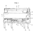
- FIG. 1 is a front view of the electromagnetic relay of the present embodiment when detaching a case covering an electromagnet and other internal parts.
- the electromagnetic relay of the present embodiment is provided with an electromagnet 12.
- the electromagnet 12 comprises a coil and an iron core which are covered by resin.
- the electromagnet 12 generates magnetic force when the coil is energized, that is, the electromagnet 12 is excited.
- the electromagnet 12 stops generating a magnetic force when energization of the coil is stopped.
- the electromagnetic relay of the present embodiment is provided with a base member 10.
- the base member 10 is formed by resin which has an electrical insulating property.
- the base member 10 includes a support part 11.
- the electromagnet 12 is placed on the base member 10 and is supported by the support part 11.
- the coil inside of the electromagnet 12 is connected to coil terminals 23 and 24.
- the electromagnetic relay has an armature 31 which is pulled by the electromagnet 12.
- the armature 31 is formed into a plate shape from a magnetic material.
- the armature 31 of the present embodiment is formed from iron.
- the armature 31 has one end fastened to a flat spring 14.
- the flat spring 14 is fastened to the base member 10.
- the flat spring 14 has elasticity and is formed so as to bias the armature 31 in a direction away from the electromagnet 12.
- the electromagnetic relay is provided with a moving electrode plate 18 as a moving member which has a moving contact 18a.
- the moving electrode plate 18 is formed into a plate shape and has elasticity.
- the moving electrode plate 18 has one end 18b which is fastened to the base member 10.
- the moving electrode plate 18 is formed by a material which has electrical conductivity.
- the moving electrode plate 18 is connected to a contact terminal 22.
- the contact terminal 22 is connected to an external electrical circuit.
- the electromagnetic relay includes a fixed electrode plate 17 as a fixed member which has a fixed contact 17a.
- the fixed electrode plate 17 is formed into a plate shape.
- the fixed electrode plate 17 is arranged so as to face the moving electrode plate 18.
- the fixed electrode plate 17 is fixed to the base member 10.
- the moving contact 18a and the fixed contact 17a are arranged so as to face each other.
- the fixed electrode plate 17 is formed by a material which has electrical conductivity.
- the fixed electrode plate 17 is connected to a contact terminal 21.
- the contact terminal 21 is connected to an external electrical circuit.
- the electromagnetic relay is provided with a card 16 as a connecting member which transmits the operation of the armature 31 to the moving electrode plate 18.
- the card 16 is connected to the other end of the armature 31 at the opposite side to the one end where the flat spring 14 is arranged.
- the card 16 engages with the armature 31 and the moving electrode plate 18.
- the card 16 is formed to be able to move in the direction which is shown by the arrow 82 and in the direction opposite to the direction which is shown by the arrow 82.
- the card 16 transmits the operation of the other end of the armature 31 to the moving electrode plate 18.
- the armature 31 separates from the electromagnet 12 due to the biasing force of the flat spring 14.
- the moving electrode plate 18 is in a state separated from the fixed electrode plate 17.
- the moving contact 18a is separated from the fixed contact 17a and electrically disconnected.
- the elastic force of the flat spring 14 causes the armature 31 to move in a direction away from the electromagnet 12.
- the other end of the armature 31 is lifted up, then the card 16 moves in a direction opposite to the arrow 82.
- the moving contact 18a separates from the fixed contact 17a and is electrically disconnected.
- the electromagnetic relay of the present embodiment can energize and deenergize the coil 2 so as to make the fixed contact 17a and the moving contact 18a contact and separate from each other.
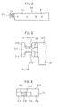
- FIG. 2 is a plan view of an armature 31 according to a first example of the present embodiment.
- the armature 31 has an armature body 31a, an engagement part 31b which is connected to the armature body 31a, and a guide part 31c which is connected to the engagement part 31b.
- the direction which is shown by the arrow 94 is defined as the longitudinal direction, while the direction which is perpendicular to the longitudinal direction is defined as the width direction.
- the engagement part 31b and the guide part 31c are formed at the other end at the opposite side to one end where the flat spring 14 is fixed.
- the armature of the present embodiment is formed from a single member.
- the armature body 31a, engagement part 31b, and guide part 31c are integrally formed.
- FIG. 3 is an enlarged plan view of part of the engagement part 31b of the armature 31 according to the first example of the present embodiment.
- FIG. 4 is a cross-sectional view when cutting the engagement part 31b of the armature 31 according to the first example of the present embodiment along the line A-A of FIG. 3 .
- the engagement part 31b is formed to become smaller in width than the armature body 31a.
- cutaway parts 31m and 31n are formed.
- the cutaway parts 31m and 31n have shapes formed by cutting away parts of the ends of the armature 31 at the both sides in the width direction.
- the engagement part 31b is configured by the part which is sandwiched between the cutaway parts 31m and 31n.
- the guide part 31c is formed so as to extend in the width direction of the armature 31 and functions to guide the card 16 to the engagement part 31b when fitting the card 16 into the engagement part 31b.
- the engagement part 31b of the first example is formed to a substantially rectangular shape when cutting in the width direction.
- the engagement part 31b has inclined parts 31d and 31e as chamfered parts obtained by chamfering angular parts.
- the inclined parts 31d and 31e are formed at the ends of the surface of the engagement part 31b in the width direction which a tab 16c of the card 16 contacts when pushing the engagement part 31b into the part sandwiched between the tab 16c and a pedestal part 16b of the card 16.
- the surfaces of the inclined parts 31d and 31e are formed in flat shapes.
- the inclined parts 31d and 31e are formed to be inclined with respect to the surface 31g of the armature body 31a.
- the inclined parts 31d and 31e are formed at the ends of the engagement part 31b at the both sides in the width direction.
- Such cutaway parts 31m and 31n and inclined part 31d and 31e of the armature 31 can be formed by cutting or grinding a material forming the engagement part 31b.
- FIG. 5 is an explanatory view of a first step in the process of production of an electromagnetic relay of the present embodiment when fitting the card 16 in the armature 31.
- FIG. 5 is a view of the electromagnetic relay from the side.
- the card 16 is fit into the engagement part 31b of the armature 31 and the armature 31 and the card 16 are connected.
- the card 16 of the present embodiment is formed in a plate shape.
- the card 16 is formed by a material which has an electrical insulating property.
- the card 16 of the present embodiment is formed from resin.
- the card 16 includes a card body 16a as a connecting member body and an insertion part 16e which extends from the card body 16a and is inserted into the moving electrode plate 18.
- the insertion part 16e has the function of pushing the moving electrode plate 18.
- the card 16 includes a pedestal part 16b which extends from the card body 16a and forms a pedestal for the engagement part 31b of the armature 31.
- the card 16 includes a deforming part 16d which extends from the card body 16a and can elastically deform.
- the deforming part 16d of the present embodiment has a first part 16f which extends from the card body 16a in the direction which is shown by the arrow 95 and a second part 16g which is bent from the first part 16f and extends in the direction which is shown by the arrow 96. In this way, the deforming part 16d has a bent shape when viewing the electromagnetic relay from the side.
- the front end of the deforming part 16d is formed with a tab 16c.
- the tab 16c is formed so as to face the pedestal part 16b. Furthermore, the tab 16c sticks out toward the pedestal part 16b.
- the distance between the pedestal part 16b and the tab 16c is made to be smaller than the thickness of the engagement part 31b of the armature 31.
- the card 16 When fitting the card 16 in the armature 31, the card 16 is moved so that the engagement part 31b of the armature 31 is arranged between the tab 16c and the pedestal part 16b. Next, as shown by the arrow 91, the card 16 is pushed into the armature 31. That is, the engagement part 31b is pushed into the part of the card 16 which is sandwiched between the pedestal part 16b and the tab 16c. At this time, the guide part 31c of the armature 31 keeps the card 16 from detaching from the engagement part 31b. For this reason, the card 16 can be easily made to move in the width direction of the engagement part 31b.
- FIG. 6 is an explanatory view of a second step when fitting the card 16 in the armature 31.
- the deforming part 16d bends and the distance between the pedestal part 16b and the tab 16c becomes larger.
- the engagement part 31b slides with respect to the pedestal part 16b and tab 16c.
- the engagement part 31b enters between the pedestal part 16b and the tab 16c.
- FIG. 7 is an explanatory view of a third step when fitting the card 16 in the armature 31.
- the card 16 can be moved to a direction as shown by the arrow 91 to arrange the engagement part 31b in the space which is surrounded by the deforming part 16d and the pedestal part 16b.
- the deforming part 16d returns to its original shape.
- the engagement part 31b is sandwiched between the pedestal part 16b and the second part 16g of the deforming part 16d. In this way, the card 16 can be fit into the engagement part 31b of the armature 31.
- the engagement part 31b of the armature 31 is arranged in the space which is surrounded by the deforming part 16d and the pedestal part 16b.
- FIG. 8 is a first enlarged cross-sectional view of part of the engagement part 31b when fitting the card 16 in the armature 31 according to the first example of the present embodiment.
- FIG. 8 shows the state where the tab 16c contacts the inclined part 31d of the engagement part 31b.
- the engagement part 31b of the armature 31 includes a surface at the side facing the pedestal part 16b and a surface at the side facing the tab 16c.
- the inclined parts 31d and 31e are formed at the end in the width direction of the surface of the engagement part 31b at the side which faces the tab 16c.
- the direction in which the engagement part 31b is inserted into the card 16 is shown by the arrow 97.
- the inclined parts 31d and 31e are inclined with respect to the direction of insertion into the card 16.
- the card 16 when the card 16 is fit into the engagement part 31b of the armature 31, the card 16 is made to move in the state with the pedestal part 16b and the tab 16c made to contact the engagement part 31b. At this time, the deforming part 16d deforms and the tab 16c is lifted up as shown by the arrow 92. Due to the reaction force of the deforming part 16d, the tab 16c is pushed toward the inclined part 31d.
- the tab 16c of the present embodiment is formed by a material which is softer than the engagement part 31b. However, the tab 16c contacts the inclined part 31d and smoothly moves along the inclined part 31d. For this reason, even if the tab 16c presses against the engagement part 31b, the tab 16c can be kept from being scraped by the engagement part 31b.
- FIG. 9 is a second enlarged cross-sectional view of part of the engagement part 31b when fitting the card 16 in the armature 31 according to the first example of the present embodiment.
- FIG. 9 shows the state where the tab 16c contacts the inclined part 31e of the engagement part 31b. If the tab 16c of the card 16 proceeds to the other end of the engagement part 31b, the tab 16c contacts the inclined part 31e. The tab 16c moves toward the original position as shown by the arrow 93. The tab 16c smoothly moves while contacting the inclined part 31e of the engagement part 31b. For this reason, the tab 16c can be kept from being scraped by the engagement part 31b.
- FIG. 10 is an enlarged plan view of part of an engagement part 35b of an armature 35 of the comparative example.
- FIG. 11 is a cross-sectional view when fitting the card 16 in the armature 35 of the comparative example.
- the armature 35 of the comparative example includes an armature body 35a, an engagement part 35b, and a guide part 35c.
- the engagement part 35b has a configuration which is sandwiched between the cutaway parts 35m and 35n.
- the engagement part 35b of the comparative example is not formed with chamfered parts at angular parts which the tab 16c of the card 16 contacts. That is, the engagement part 35b is not formed with inclined parts at the ends in the width direction but has sharp corner parts 35d and 35e.
- the engagement part 35b is formed to have a rectangular cross-sectional shape.
- the tab 16c contacts one angular part 35d of the engagement part 35b.
- the angular part 35d has a sharp shape and, furthermore, the engagement part 35b is formed by a material which is harder than the tab 16c, sometimes the tab 16c is scraped when the tab 16c slides against the angular part 35d.
- the tab 16c contacts the angular part 35e by making the card 16 move as shown by the arrow 91, sometimes the tab 16c is scraped.
- the tab 16c may be scraped and scrapings are formed. Scrapings remaining inside the electromagnetic relay may cause poor connection between the contacts.
- the armature 31 of the present embodiment is formed with inclined parts 31d and 31e obtained by chamfering the angular parts of the engagement part 31b at the ends of the surface in the width direction which the tab 16c contacts when the engagement part 31b is pushed between the pedestal part 16b and the tab 16c. For this reason, it is possible to keep the tab 16c from being scraped. It is possible to keep scrapings from being produced in the process of production of an electromagnetic relay and to keep scrapings from remaining inside the electromagnetic relay. As a result, it is possible to suppress defects in the electromagnetic relay.
- FIG. 12 is an enlarged plan view of a part of an engagement part 32b of an armature 32 according to a second example of the present embodiment.
- FIG. 13 is a cross-sectional view when fitting the card 16 in the armature 32 according to the second example of the present embodiment.
- the armature 32 includes an armature body 32a, an engagement part 32b, and a guide part 32c.
- the armature 32 is formed with a cutaway part 32m at one end in the width direction and is formed with a recess part 32f at the other end of the width direction.
- the recess part 32f is formed so as to be recessed from the surface of the engagement part 32b.
- the engagement part 32b is configured by a part which is sandwiched between the cutaway part 32m and the recess part 32f.
- inclined parts 32d and 32e are formed at the ends at the both sides in the width direction.
- the recess part 32f is formed so as to be able to hold the tab 16c inside it. Further, the recess part 32f has a depth giving a clearance between the tab 16c and the bottom surface of the recess part 32f when holding the tab 16c.
- an inclined part 32g is formed in addition to the inclined part 32e.
- Such a recess part 32f can, for example, be formed by pressing the member forming the base material by a die. That is, it may be formed by press forming the base material. Alternatively, it may be formed by cutting the surface of a member forming the base material.
- the ends of the engagement part 32b at the both sides in the width direction are formed with inclined parts 32d and 32e, so it is possible to keep the tab 16c of the card 16 from being scraped when fitting the card 16 into the armature 32. As a result, it is possible to keep scrapings from remaining inside of the electromagnetic relay.
- the armature 32 is formed with a recess part 32f at the other end in the width direction.
- the armature 32 has a structure where the recess part 32f is connected to the engagement part 32b and guide part 32c. Therefore, the engagement part 32b and guide part 32c can be supported by the part where the recess part 32f is formed. That is, the armature 32 has a structure where it is reinforced so as to suppress deformation of the engagement part 32b and guide part 32c. In particular, in the production of the armature 32, it is possible to suppress deformation of the engagement part 32b and the guide part 32c and possible to suppress the occurrence of defective products.
- FIG. 14 is an enlarged plan view of part of an engagement part 35b of an armature 35 of a comparative example.
- the armature 35 of the comparative example has a structure which does not have the recessed part 32f and where the engagement part 35b is not reinforced. For this reason, in the process of production of the armature 35, sometimes the engagement part 35b ends up deforming. Further, sometimes the guide part 35c ends up deforming. For example, in the process of washing a large number of armatures 35 at one time, sometimes the armatures 35 strike each other and, as shown in FIG. 14 , the engagement parts 35b or the guide parts 35c end up bending. Alternatively, sometimes the engagement parts 35b or guide parts 35c end up being twisted.
- the armature 32 of the present embodiment has a structure which is reinforced so as to suppress deformation of the part of the engagement part 32b, so deformation of the engagement part 32b and guide part 32c can be suppressed.
- FIG. 15 is an enlarged plan view of part of the engagement part 33b of the armature 33 according to a third example of the present embodiment.
- FIG. 16 is a cross-sectional view of part of the engagement part 33b of the armature 33 according to the third example of the present embodiment.
- FIG. 16 is a cross-sectional view when cutting along the line B-B of FIG. 15 .
- the armature 33 according to the third example includes an armature body 33a, engagement part 33b, and guide part 33c.
- the armature 33 is formed with a cutaway part 33m at one end in the width direction and is formed with a recess part 33f at the other end.
- the engagement part 33b is configured by the part which is sandwiched between the cutaway part 33m and the recess part 33f.
- the recess part 33f of the armature 33 is formed with a rectangular cross-sectional shape.
- the ends of the engagement part 33b at the both sides in the width direction are structured without inclined parts. Even in an armature 33 which includes such an engagement part 33b and recess part 33f, deformation of the engagement part 33b and the guide part 33c in the process of production of the armature 33 can be suppressed. Therefore, defects in the armature 33 can be suppressed.
- the card is made to move relative to the armature so as to fit the card in the engagement part of the armature, but the invention is not limited to this. It is also possible to make the armature move relative to the card so as to fit the card in the engagement part of the armature.
- a chamfered part of the present embodiment is formed with a flat surface, but the invention is not limited to this. It may also be formed into a curved surface.
- the electromagnetic relay of the present embodiment brings two contacts into contact with each other, but the invention is not limited to this.
- the present invention can also be applied to an electromagnetic relay which has three or more contacts and electrically connects, disconnects, or switches any contacts.
Landscapes
- Physics & Mathematics (AREA)
- Electromagnetism (AREA)
- Electromagnets (AREA)
Abstract
Description
- The present invention relates to an electromagnetic relay.
- As a device which is arranged in an electrical circuit to electrically connect and disconnect it, an electromagnetic relay is known. An electromagnetic relay is provided with an electromagnet which includes a coil, an armature which faces the electromagnet, and electrodes which are connected to the armature and include contacts. In the electromagnetic relay, when the coil is energized, the armature is pulled by the electromagnet causing the armature to move. Due to movement of the armature, a plurality of contacts are electrically contacted or separated.
- Japanese Patent Publication No.
7-312161 - Japanese Examined Utility Model Publication No.
63-47000B2 - Japanese Patent Publication No.
9-245599A - As disclosed in the above patent literature, it is known to arrange a card between an armature and electrodes to transmit the operation of the armature to the electrodes in the electromagnetic relay. The electromagnetic relay which is provided with the card is formed so that the card moves corresponding to the operation of the armature and the electrodes move corresponding to the operation of the card. The armature is formed by iron etc. since it is formed by for example a magnetic body. As opposed to this, the card is formed by an insulating material of resin etc.
- In the production of an electromagnetic relay, the card has to be connected to the armature, but in the process of connecting the card to the armature, sometimes part of the card is scraped off. For example, sometimes the connecting part of a card is fit into a connecting part of an armature. The armature is formed by iron or another hard material, while the card is formed by resin or other soft material, so when fitting the card in the armature, sometimes the part of the card which slides against the armature is scraped off and scrapings are produced.
- After assembling the electromagnet or the card or other inside parts, the inside parts are covered by a case. In this regard, the scrapings of the card sometimes remain in the case. If the scrapings of the card remain inside the case, for example, they sometimes stick to the contacts and cause poor connection between the contacts.
- Further, an armature is sometimes formed with a narrow part for fitting the card. In this regard, sometimes the strength of the part for fitting the card is insufficient and the part for fitting the card deforms in the production of the armature. If the part for fitting the card was not formed to the desired shape, the armature is treated as defective.
- The present invention has as its object the provision of an electromagnetic relay which suppresses defects in the process of production.
- An electromagnetic relay of the present invention is provided with an electromagnet which includes a coil, an armature which is pulled by the electromagnet, a moving member which has a moving contact, and a connecting member which engages with the armature and the moving member and transmits the operation of the armature to the moving member. The armature includes an armature body and an engagement part which engages with the connecting member. The connecting member includes a connecting member body, a pedestal part which extends from the connecting member body, a deforming part which extends from the connecting member body and can elastically deform, and a tab which is formed at the end of the deforming part and sticks out toward the pedestal part. The deforming part has a first part which extends from the connecting member body and a second part which extends bent from the first part and deforms when the engagement part is pushed between the pedestal part and the tab. The engagement part is sandwiched between the pedestal part and second part when the engagement part engages with the connecting member.
- In the above invention, the engagement part may be configured to have a chamfered part where an angular part at the end of a surface of the engagement part in the width direction at which the tab contacts when the engagement part is pushed between the pedestal part and the tab is chamfered.
- In the above invention, the armature may have cutaway parts which are formed at the ends at the both sides in the width direction, and the engagement part may be configured by a part which is sandwiched by the cutaway parts.
- In the above invention, the armature may include a cutaway part which is formed at one end in the width direction and a recess part which is formed at the other end in the width direction, and the engagement part may be configured by a part which is sandwiched by the cutaway part and the recess part.
- In the above invention, the engagement part may be configured by a part which is sandwiched between a cutaway part which is formed at one end of the armature in the width direction and a recess part which is formed at the other end in the width direction.
-
-
FIG. 1 is a schematic front view when detaching a case in an electromagnetic relay of an embodiment. -
FIG. 2 is a plan view of an armature according to a first example of the embodiment. -
FIG. 3 is an enlarged plan view of a part of an engagement part of the armature according to the first example of the embodiment. -
FIG. 4 is a schematic cross-sectional view when cut at the part of an engagement part of the armature according to the first example of the embodiment. -
FIG. 5 is a schematic view which explains a first step when fitting a card in the armature according to the first example of the embodiment. -
FIG. 6 is a schematic view which explains a second step when fitting a card in the armature according to the first example of the embodiment. -
FIG. 7 is a schematic view which explains a third step when fitting a card in the armature according to the first example of the embodiment. -
FIG. 8 is a cross-sectional view when a tab of a card abuts against one inclined part of an engagement part when fitting the card in the armature according to the first example of the embodiment. -
FIG. 9 is a cross-sectional view when a tab of a card abuts against another inclined part of an engagement part when fitting the card in the armature according to the first example of the embodiment. -
FIG. 10 is an enlarged plan view of an engagement part of an armature of a comparative example. -
FIG. 11 is a cross-sectional view when inserting a card in the armature of the comparative example. -
FIG. 12 is an enlarged plan view of a part of an engagement part of an armature according to a second example of the embodiment. -
FIG. 13 is an enlarged cross-sectional view when fitting a card in the armature according to the second example of the embodiment. -
FIG. 14 is an enlarged plan view of an engagement part which explains defects in the armature of the comparative example. -
FIG. 15 is an enlarged plan view of a part of an engagement part of an armature according to a third example of the embodiment. -
FIG. 16 is a cross-sectional view cutting a part of an engagement part of the armature according to the third example of the embodiment. - Referring to
FIG. 1 to FIG. 16 , an electromagnetic relay will be explained. -
FIG. 1 is a front view of the electromagnetic relay of the present embodiment when detaching a case covering an electromagnet and other internal parts. - The electromagnetic relay of the present embodiment is provided with an
electromagnet 12. In the present embodiment, theelectromagnet 12 comprises a coil and an iron core which are covered by resin. Theelectromagnet 12 generates magnetic force when the coil is energized, that is, theelectromagnet 12 is excited. Theelectromagnet 12 stops generating a magnetic force when energization of the coil is stopped. - The electromagnetic relay of the present embodiment is provided with a
base member 10. In the present embodiment, thebase member 10 is formed by resin which has an electrical insulating property. Thebase member 10 includes asupport part 11. Theelectromagnet 12 is placed on thebase member 10 and is supported by thesupport part 11. The coil inside of theelectromagnet 12 is connected tocoil terminals - The electromagnetic relay has an
armature 31 which is pulled by theelectromagnet 12. Thearmature 31 is formed into a plate shape from a magnetic material. Thearmature 31 of the present embodiment is formed from iron. Thearmature 31 has one end fastened to aflat spring 14. Theflat spring 14 is fastened to thebase member 10. Theflat spring 14 has elasticity and is formed so as to bias thearmature 31 in a direction away from theelectromagnet 12. - The electromagnetic relay is provided with a moving
electrode plate 18 as a moving member which has a movingcontact 18a. The movingelectrode plate 18 is formed into a plate shape and has elasticity. The movingelectrode plate 18 has oneend 18b which is fastened to thebase member 10. The movingelectrode plate 18 is formed by a material which has electrical conductivity. The movingelectrode plate 18 is connected to acontact terminal 22. Thecontact terminal 22 is connected to an external electrical circuit. - The electromagnetic relay includes a fixed
electrode plate 17 as a fixed member which has a fixedcontact 17a. The fixedelectrode plate 17 is formed into a plate shape. The fixedelectrode plate 17 is arranged so as to face the movingelectrode plate 18. The fixedelectrode plate 17 is fixed to thebase member 10. The movingcontact 18a and the fixedcontact 17a are arranged so as to face each other. The fixedelectrode plate 17 is formed by a material which has electrical conductivity. The fixedelectrode plate 17 is connected to acontact terminal 21. Thecontact terminal 21 is connected to an external electrical circuit. - The electromagnetic relay is provided with a
card 16 as a connecting member which transmits the operation of thearmature 31 to the movingelectrode plate 18. Thecard 16 is connected to the other end of thearmature 31 at the opposite side to the one end where theflat spring 14 is arranged. Thecard 16 engages with thearmature 31 and the movingelectrode plate 18. Thecard 16 is formed to be able to move in the direction which is shown by thearrow 82 and in the direction opposite to the direction which is shown by thearrow 82. Thecard 16 transmits the operation of the other end of thearmature 31 to the movingelectrode plate 18. - When the coil of the
electromagnet 12 is not being energized, thearmature 31 separates from theelectromagnet 12 due to the biasing force of theflat spring 14. At this time, the movingelectrode plate 18 is in a state separated from the fixedelectrode plate 17. The movingcontact 18a is separated from the fixedcontact 17a and electrically disconnected. - When energizing the coil of the
electromagnet 12, a magnetic field is generated around the core of theelectromagnet 12 and thearmature 31 is pulled to theelectromagnet 12 as shown by thearrow 81. The other end of thearmature 31 pushes thecard 16, whereby thecard 16 moves in the direction which is shown by thearrow 82 and the end of the movingelectrode plate 18 is pushed. When the movingelectrode plate 18 is pushed by thecard 16, the movingelectrode plate 18 bends toward the fixedelectrode plate 17 as shown by thearrow 83. The movingcontact 18a moves toward the fixedcontact 17a and contacts the fixedcontact 17a. As a result, electrical conduction is achieved. - If stopping the energization of the coil of the
electromagnet 12, the elastic force of theflat spring 14 causes thearmature 31 to move in a direction away from theelectromagnet 12. The other end of thearmature 31 is lifted up, then thecard 16 moves in a direction opposite to thearrow 82. The movingcontact 18a separates from the fixedcontact 17a and is electrically disconnected. The electromagnetic relay of the present embodiment can energize and deenergize the coil 2 so as to make the fixedcontact 17a and the movingcontact 18a contact and separate from each other. -
FIG. 2 is a plan view of anarmature 31 according to a first example of the present embodiment. In the first example, thearmature 31 has anarmature body 31a, anengagement part 31b which is connected to thearmature body 31a, and aguide part 31c which is connected to theengagement part 31b. In thearmature 31, the direction which is shown by thearrow 94 is defined as the longitudinal direction, while the direction which is perpendicular to the longitudinal direction is defined as the width direction. In the longitudinal direction of thearmature body 31a, theengagement part 31b and theguide part 31c are formed at the other end at the opposite side to one end where theflat spring 14 is fixed. The armature of the present embodiment is formed from a single member. Thearmature body 31a,engagement part 31b, and guidepart 31c are integrally formed. -
FIG. 3 is an enlarged plan view of part of theengagement part 31b of thearmature 31 according to the first example of the present embodiment.FIG. 4 is a cross-sectional view when cutting theengagement part 31b of thearmature 31 according to the first example of the present embodiment along the line A-A ofFIG. 3 . Referring toFIG. 2 to FIG. 4 , theengagement part 31b is formed to become smaller in width than thearmature body 31a. At the both sides of theengagement part 31b in the width direction,cutaway parts cutaway parts armature 31 at the both sides in the width direction. In this way, theengagement part 31b is configured by the part which is sandwiched between thecutaway parts guide part 31c is formed so as to extend in the width direction of thearmature 31 and functions to guide thecard 16 to theengagement part 31b when fitting thecard 16 into theengagement part 31b. - The
engagement part 31b of the first example is formed to a substantially rectangular shape when cutting in the width direction. Theengagement part 31b has inclinedparts inclined parts engagement part 31b in the width direction which atab 16c of thecard 16 contacts when pushing theengagement part 31b into the part sandwiched between thetab 16c and apedestal part 16b of thecard 16. The surfaces of theinclined parts inclined parts surface 31g of thearmature body 31a. Theinclined parts engagement part 31b at the both sides in the width direction. Suchcutaway parts inclined part armature 31 can be formed by cutting or grinding a material forming theengagement part 31b. -
FIG. 5 is an explanatory view of a first step in the process of production of an electromagnetic relay of the present embodiment when fitting thecard 16 in thearmature 31.FIG. 5 is a view of the electromagnetic relay from the side. In the process of production, thecard 16 is fit into theengagement part 31b of thearmature 31 and thearmature 31 and thecard 16 are connected. Referring toFIG. 1 andFIG. 5 , thecard 16 of the present embodiment is formed in a plate shape. Thecard 16 is formed by a material which has an electrical insulating property. Thecard 16 of the present embodiment is formed from resin. - The
card 16 includes acard body 16a as a connecting member body and aninsertion part 16e which extends from thecard body 16a and is inserted into the movingelectrode plate 18. Theinsertion part 16e has the function of pushing the movingelectrode plate 18. Thecard 16 includes apedestal part 16b which extends from thecard body 16a and forms a pedestal for theengagement part 31b of thearmature 31. Thecard 16 includes a deformingpart 16d which extends from thecard body 16a and can elastically deform. - The deforming
part 16d of the present embodiment has afirst part 16f which extends from thecard body 16a in the direction which is shown by thearrow 95 and asecond part 16g which is bent from thefirst part 16f and extends in the direction which is shown by the arrow 96. In this way, the deformingpart 16d has a bent shape when viewing the electromagnetic relay from the side. The front end of the deformingpart 16d is formed with atab 16c. Thetab 16c is formed so as to face thepedestal part 16b. Furthermore, thetab 16c sticks out toward thepedestal part 16b. The distance between thepedestal part 16b and thetab 16c is made to be smaller than the thickness of theengagement part 31b of thearmature 31. - When fitting the
card 16 in thearmature 31, thecard 16 is moved so that theengagement part 31b of thearmature 31 is arranged between thetab 16c and thepedestal part 16b. Next, as shown by thearrow 91, thecard 16 is pushed into thearmature 31. That is, theengagement part 31b is pushed into the part of thecard 16 which is sandwiched between thepedestal part 16b and thetab 16c. At this time, theguide part 31c of thearmature 31 keeps thecard 16 from detaching from theengagement part 31b. For this reason, thecard 16 can be easily made to move in the width direction of theengagement part 31b. -
FIG. 6 is an explanatory view of a second step when fitting thecard 16 in thearmature 31. By pushing thecard 16 into thearmature 31, the deformingpart 16d bends and the distance between thepedestal part 16b and thetab 16c becomes larger. Theengagement part 31b slides with respect to thepedestal part 16b andtab 16c. Theengagement part 31b enters between thepedestal part 16b and thetab 16c. -
FIG. 7 is an explanatory view of a third step when fitting thecard 16 in thearmature 31. After the second step, thecard 16 can be moved to a direction as shown by thearrow 91 to arrange theengagement part 31b in the space which is surrounded by the deformingpart 16d and thepedestal part 16b. At this time, the deformingpart 16d returns to its original shape. Theengagement part 31b is sandwiched between thepedestal part 16b and thesecond part 16g of the deformingpart 16d. In this way, thecard 16 can be fit into theengagement part 31b of thearmature 31. In the state where thecard 16 and thearmature 31 are connected, theengagement part 31b of thearmature 31 is arranged in the space which is surrounded by the deformingpart 16d and thepedestal part 16b. -
FIG. 8 is a first enlarged cross-sectional view of part of theengagement part 31b when fitting thecard 16 in thearmature 31 according to the first example of the present embodiment.FIG. 8 shows the state where thetab 16c contacts theinclined part 31d of theengagement part 31b. Theengagement part 31b of thearmature 31 includes a surface at the side facing thepedestal part 16b and a surface at the side facing thetab 16c. Theinclined parts engagement part 31b at the side which faces thetab 16c. The direction in which theengagement part 31b is inserted into thecard 16 is shown by thearrow 97. Theinclined parts card 16. - As explained above, when the
card 16 is fit into theengagement part 31b of thearmature 31, thecard 16 is made to move in the state with thepedestal part 16b and thetab 16c made to contact theengagement part 31b. At this time, the deformingpart 16d deforms and thetab 16c is lifted up as shown by thearrow 92. Due to the reaction force of the deformingpart 16d, thetab 16c is pushed toward theinclined part 31d. Thetab 16c of the present embodiment is formed by a material which is softer than theengagement part 31b. However, thetab 16c contacts theinclined part 31d and smoothly moves along theinclined part 31d. For this reason, even if thetab 16c presses against theengagement part 31b, thetab 16c can be kept from being scraped by theengagement part 31b. -
FIG. 9 is a second enlarged cross-sectional view of part of theengagement part 31b when fitting thecard 16 in thearmature 31 according to the first example of the present embodiment.FIG. 9 shows the state where thetab 16c contacts theinclined part 31e of theengagement part 31b. If thetab 16c of thecard 16 proceeds to the other end of theengagement part 31b, thetab 16c contacts theinclined part 31e. Thetab 16c moves toward the original position as shown by thearrow 93. Thetab 16c smoothly moves while contacting theinclined part 31e of theengagement part 31b. For this reason, thetab 16c can be kept from being scraped by theengagement part 31b. - Here, an armature of a comparative example will be explained.
FIG. 10 is an enlarged plan view of part of anengagement part 35b of anarmature 35 of the comparative example.FIG. 11 is a cross-sectional view when fitting thecard 16 in thearmature 35 of the comparative example. Thearmature 35 of the comparative example includes anarmature body 35a, anengagement part 35b, and aguide part 35c. Theengagement part 35b has a configuration which is sandwiched between thecutaway parts - The
engagement part 35b of the comparative example is not formed with chamfered parts at angular parts which thetab 16c of thecard 16 contacts. That is, theengagement part 35b is not formed with inclined parts at the ends in the width direction but hassharp corner parts engagement part 35b is formed to have a rectangular cross-sectional shape. - If the
card 16 is made to move relative to thearmature 35 of the comparative example as shown by thearrow 91, thetab 16c contacts oneangular part 35d of theengagement part 35b. At this time, since theangular part 35d has a sharp shape and, furthermore, theengagement part 35b is formed by a material which is harder than thetab 16c, sometimes thetab 16c is scraped when thetab 16c slides against theangular part 35d. Furthermore, when thetab 16c contacts theangular part 35e by making thecard 16 move as shown by thearrow 91, sometimes thetab 16c is scraped. In this way, in thearmature 35 of the comparative example, when fitting thecard 16 in thearmature 35, thetab 16c may be scraped and scrapings are formed. Scrapings remaining inside the electromagnetic relay may cause poor connection between the contacts. - Referring to
FIG. 8 andFIG. 9 , as opposed to the comparative example, thearmature 31 of the present embodiment is formed withinclined parts engagement part 31b at the ends of the surface in the width direction which thetab 16c contacts when theengagement part 31b is pushed between thepedestal part 16b and thetab 16c. For this reason, it is possible to keep thetab 16c from being scraped. It is possible to keep scrapings from being produced in the process of production of an electromagnetic relay and to keep scrapings from remaining inside the electromagnetic relay. As a result, it is possible to suppress defects in the electromagnetic relay. -
FIG. 12 is an enlarged plan view of a part of anengagement part 32b of anarmature 32 according to a second example of the present embodiment.FIG. 13 is a cross-sectional view when fitting thecard 16 in thearmature 32 according to the second example of the present embodiment. Referring toFIG. 12 and FIG. 13 , thearmature 32 includes anarmature body 32a, anengagement part 32b, and aguide part 32c. Thearmature 32 is formed with acutaway part 32m at one end in the width direction and is formed with arecess part 32f at the other end of the width direction. Therecess part 32f is formed so as to be recessed from the surface of theengagement part 32b. Theengagement part 32b is configured by a part which is sandwiched between thecutaway part 32m and therecess part 32f. At the surface which thetab 16c contacts when theengagement part 32b is pushed between thepedestal part 16b and thetab 16c,inclined parts - The
recess part 32f is formed so as to be able to hold thetab 16c inside it. Further, therecess part 32f has a depth giving a clearance between thetab 16c and the bottom surface of therecess part 32f when holding thetab 16c. At the ends of therecess part 32f at the both sides in the width direction, aninclined part 32g is formed in addition to theinclined part 32e. Such arecess part 32f can, for example, be formed by pressing the member forming the base material by a die. That is, it may be formed by press forming the base material. Alternatively, it may be formed by cutting the surface of a member forming the base material. - In the electromagnetic relay which is provided with an
armature 32 as well, the ends of theengagement part 32b at the both sides in the width direction are formed withinclined parts tab 16c of thecard 16 from being scraped when fitting thecard 16 into thearmature 32. As a result, it is possible to keep scrapings from remaining inside of the electromagnetic relay. - Further, the
armature 32 is formed with arecess part 32f at the other end in the width direction. Thearmature 32 has a structure where therecess part 32f is connected to theengagement part 32b and guidepart 32c. Therefore, theengagement part 32b and guidepart 32c can be supported by the part where therecess part 32f is formed. That is, thearmature 32 has a structure where it is reinforced so as to suppress deformation of theengagement part 32b and guidepart 32c. In particular, in the production of thearmature 32, it is possible to suppress deformation of theengagement part 32b and theguide part 32c and possible to suppress the occurrence of defective products. -
FIG. 14 is an enlarged plan view of part of anengagement part 35b of anarmature 35 of a comparative example. Thearmature 35 of the comparative example has a structure which does not have the recessedpart 32f and where theengagement part 35b is not reinforced. For this reason, in the process of production of thearmature 35, sometimes theengagement part 35b ends up deforming. Further, sometimes theguide part 35c ends up deforming. For example, in the process of washing a large number ofarmatures 35 at one time, sometimes thearmatures 35 strike each other and, as shown inFIG. 14 , theengagement parts 35b or theguide parts 35c end up bending. Alternatively, sometimes theengagement parts 35b or guideparts 35c end up being twisted. As opposed to this, thearmature 32 of the present embodiment has a structure which is reinforced so as to suppress deformation of the part of theengagement part 32b, so deformation of theengagement part 32b and guidepart 32c can be suppressed. -
FIG. 15 is an enlarged plan view of part of theengagement part 33b of thearmature 33 according to a third example of the present embodiment.FIG. 16 is a cross-sectional view of part of theengagement part 33b of thearmature 33 according to the third example of the present embodiment.FIG. 16 is a cross-sectional view when cutting along the line B-B ofFIG. 15 . Thearmature 33 according to the third example includes anarmature body 33a,engagement part 33b, and guidepart 33c. Thearmature 33 is formed with acutaway part 33m at one end in the width direction and is formed with arecess part 33f at the other end. Theengagement part 33b is configured by the part which is sandwiched between thecutaway part 33m and therecess part 33f. - The
recess part 33f of thearmature 33 is formed with a rectangular cross-sectional shape. The ends of theengagement part 33b at the both sides in the width direction are structured without inclined parts. Even in anarmature 33 which includes such anengagement part 33b andrecess part 33f, deformation of theengagement part 33b and theguide part 33c in the process of production of thearmature 33 can be suppressed. Therefore, defects in thearmature 33 can be suppressed. - In the present embodiment, the card is made to move relative to the armature so as to fit the card in the engagement part of the armature, but the invention is not limited to this. It is also possible to make the armature move relative to the card so as to fit the card in the engagement part of the armature.
- A chamfered part of the present embodiment is formed with a flat surface, but the invention is not limited to this. It may also be formed into a curved surface.
- The electromagnetic relay of the present embodiment brings two contacts into contact with each other, but the invention is not limited to this. The present invention can also be applied to an electromagnetic relay which has three or more contacts and electrically connects, disconnects, or switches any contacts.
- The above embodiments may be suitably combined. In the above figures, the same or corresponding parts are assigned the same reference notations. Note that the above embodiments are illustrations and do not limit the invention. Further, in the embodiments, changes which are shown in the claims are included.
Claims (5)
- An electromagnetic relay comprising an electromagnet which includes a coil, an armature which is pulled by said electromagnet, a moving member which has a moving contact, and a connecting member which engages with said armature and said moving member and transmits an operation of said armature to said moving member, characterized in that,
said armature includes an armature body and an engagement part which engages with said connecting member,
said connecting member includes a connecting member body, a pedestal part which extends from said connecting member body, a deforming part which extends from said connecting member body and can elastically deform, and a tab which is formed at the end of said deforming part and sticks out toward said pedestal part,
said deforming part has a first part which extends from said connecting member body and a second part which extends bent from said first part and deforms when said engagement part is pushed between said pedestal part and said tab, and
said engagement part is sandwiched between said pedestal part and said second part when said engagement part engages with said connecting member. - The electromagnetic relay as set forth in claim 1, wherein
said engagement part is configured to have a chamfered part where an angular part at the end of a surface of said engagement part in the width direction at which said tab contacts when said engagement part is pushed between said pedestal part and said tab is chamfered. - The electromagnetic relay as set forth in claim 1 or claim 2, wherein
said armature has cutaway parts which are formed at the ends at the both sides in the width direction, and
said engagement part is configured by a part which is sandwiched by said cutaway parts. - The electromagnetic relay as set forth in claim 1 or claim 2, wherein
said armature includes a cutaway part which is formed at one end in the width direction and a recess part which is formed at the other end in the width direction, and
said engagement part is configured by a part which is sandwiched by said cutaway part and said recess part. - The electromagnetic as set forth in claim 1, wherein said engagement part is configured by a part which is sandwiched between a cutaway part which is formed at one end of said armature in the width direction and a recess part which is formed at the other end in width direction.
Applications Claiming Priority (1)
| Application Number | Priority Date | Filing Date | Title |
|---|---|---|---|
| JP2013008531A JP2014139898A (en) | 2013-01-21 | 2013-01-21 | Electromagnetic relay |
Publications (2)
| Publication Number | Publication Date |
|---|---|
| EP2757569A1 true EP2757569A1 (en) | 2014-07-23 |
| EP2757569B1 EP2757569B1 (en) | 2017-04-19 |
Family
ID=49918640
Family Applications (1)
| Application Number | Title | Priority Date | Filing Date |
|---|---|---|---|
| EP14151276.4A Active EP2757569B1 (en) | 2013-01-21 | 2014-01-15 | Electromagnetic relay |
Country Status (4)
| Country | Link |
|---|---|
| US (1) | US9064665B2 (en) |
| EP (1) | EP2757569B1 (en) |
| JP (1) | JP2014139898A (en) |
| CN (1) | CN103943413A (en) |
Families Citing this family (9)
| Publication number | Priority date | Publication date | Assignee | Title |
|---|---|---|---|---|
| JP6341361B2 (en) * | 2013-12-13 | 2018-06-13 | パナソニックIpマネジメント株式会社 | Electromagnetic relay |
| JP6664978B2 (en) * | 2016-01-29 | 2020-03-13 | 富士通コンポーネント株式会社 | Electromagnetic relay |
| JP2018006209A (en) * | 2016-07-05 | 2018-01-11 | 富士通コンポーネント株式会社 | Electromagnetic relay |
| SG10201703450TA (en) * | 2017-04-27 | 2018-11-29 | Schneider Electric Asia Pte Ltd | A card structure for use in an electromechanical relay and an electromechanical relay comprising the card structure |
| JP6897409B2 (en) * | 2017-08-04 | 2021-06-30 | オムロン株式会社 | Electromagnetic relay |
| CN108470660B (en) * | 2018-04-04 | 2019-07-30 | 佛山市顺德区航腾电子有限公司 | A kind of electromagnetic relay |
| JP7149824B2 (en) * | 2018-11-30 | 2022-10-07 | 富士通コンポーネント株式会社 | electromagnetic relay |
| CN110164733B (en) * | 2019-05-20 | 2024-05-17 | 厦门宏发电声股份有限公司 | Electromagnetic relay with large suction force and strong shock resistance |
| JP7638633B2 (en) * | 2020-06-30 | 2025-03-04 | Fclコンポーネント株式会社 | Electromagnetic Relay |
Citations (7)
| Publication number | Priority date | Publication date | Assignee | Title |
|---|---|---|---|---|
| JPS6347000B2 (en) | 1980-07-28 | 1988-09-20 | Fujitsu Ltd | |
| JPH07312161A (en) | 1994-05-18 | 1995-11-28 | Mitsuki Nagamoto | Single stable type polarized electromagnet |
| JPH09245599A (en) | 1996-03-12 | 1997-09-19 | Omron Corp | Electromagnetic relay |
| US5969586A (en) * | 1994-03-15 | 1999-10-19 | Omron Corporation | Electromagnetic relay |
| CZ9904377A3 (en) * | 1998-12-07 | 2000-12-13 | Matsushita Electric Works, Ltd | Electromagnetic Relay |
| US20020130741A1 (en) * | 2001-03-09 | 2002-09-19 | Omron Corporation | Relay |
| EP1420428A1 (en) * | 2002-11-12 | 2004-05-19 | Omron Corporation | Electromagnetic relay |
Family Cites Families (9)
| Publication number | Priority date | Publication date | Assignee | Title |
|---|---|---|---|---|
| JPS6347000A (en) | 1986-08-12 | 1988-02-27 | 三菱電機株式会社 | Attitude controller for artificial satellite |
| US6486760B2 (en) | 1998-12-07 | 2002-11-26 | Matsushita Electric Works, Ltd. | Electromagnetic relay |
| JP2001155610A (en) * | 1999-11-26 | 2001-06-08 | Takamisawa Electric Co Ltd | Electromagnetic relay |
| JP4131160B2 (en) * | 2002-11-08 | 2008-08-13 | オムロン株式会社 | Electromagnetic relay |
| JP4131161B2 (en) * | 2002-11-12 | 2008-08-13 | オムロン株式会社 | Electromagnetic relay |
| JP4389653B2 (en) * | 2004-04-30 | 2009-12-24 | オムロン株式会社 | Electromagnetic relay |
| JP4389652B2 (en) * | 2004-04-30 | 2009-12-24 | オムロン株式会社 | Electromagnetic relay |
| JP4742954B2 (en) * | 2006-03-31 | 2011-08-10 | オムロン株式会社 | Electromagnetic relay |
| JP2010231992A (en) * | 2009-03-26 | 2010-10-14 | Panasonic Electric Works Co Ltd | Electromagnetic relay |
-
2013
- 2013-01-21 JP JP2013008531A patent/JP2014139898A/en active Pending
- 2013-10-31 US US14/068,689 patent/US9064665B2/en active Active
- 2013-12-19 CN CN201310703335.5A patent/CN103943413A/en active Pending
-
2014
- 2014-01-15 EP EP14151276.4A patent/EP2757569B1/en active Active
Patent Citations (7)
| Publication number | Priority date | Publication date | Assignee | Title |
|---|---|---|---|---|
| JPS6347000B2 (en) | 1980-07-28 | 1988-09-20 | Fujitsu Ltd | |
| US5969586A (en) * | 1994-03-15 | 1999-10-19 | Omron Corporation | Electromagnetic relay |
| JPH07312161A (en) | 1994-05-18 | 1995-11-28 | Mitsuki Nagamoto | Single stable type polarized electromagnet |
| JPH09245599A (en) | 1996-03-12 | 1997-09-19 | Omron Corp | Electromagnetic relay |
| CZ9904377A3 (en) * | 1998-12-07 | 2000-12-13 | Matsushita Electric Works, Ltd | Electromagnetic Relay |
| US20020130741A1 (en) * | 2001-03-09 | 2002-09-19 | Omron Corporation | Relay |
| EP1420428A1 (en) * | 2002-11-12 | 2004-05-19 | Omron Corporation | Electromagnetic relay |
Also Published As
| Publication number | Publication date |
|---|---|
| CN103943413A (en) | 2014-07-23 |
| US20140203898A1 (en) | 2014-07-24 |
| EP2757569B1 (en) | 2017-04-19 |
| JP2014139898A (en) | 2014-07-31 |
| US9064665B2 (en) | 2015-06-23 |
Similar Documents
| Publication | Publication Date | Title |
|---|---|---|
| EP2757569B1 (en) | Electromagnetic relay | |
| EP2019405A1 (en) | Electromagnetic relay | |
| US7283026B2 (en) | Electromagnetic relay | |
| CN111599646A (en) | Electromagnetic relays and bases | |
| JP6084133B2 (en) | connector | |
| US20150081944A1 (en) | Usb memory having non-insertion type connector and gender connected thereto | |
| US8228143B2 (en) | Assembly of electromagnetic relay and circuit board | |
| US9437968B2 (en) | Magnet connector | |
| US20160086755A1 (en) | Electromagnetic relay | |
| CN108028155B (en) | Electromagnetic Relay | |
| JP2017142971A (en) | Press-fit terminal | |
| US9966213B2 (en) | Electronic device and manufacturing method therefor | |
| EP2908327A1 (en) | Electromagnetic relay | |
| US8169280B2 (en) | Relay | |
| JP4645663B2 (en) | relay | |
| EP2503582A1 (en) | Electromagnetic relay | |
| JP5722850B2 (en) | Electromagnet device and electromagnetic relay | |
| JP5763447B2 (en) | connector | |
| EP3242312A1 (en) | Electromagnetic relay | |
| EP4657485A1 (en) | Relay | |
| CN112582210A (en) | Relay with a movable contact | |
| US7710223B2 (en) | Relay | |
| JP2016207793A (en) | Electronic component | |
| JP2007134553A (en) | Actuator for control equipment | |
| CN115997268A (en) | Non-magnetic plate, electromagnetic contactor, non-magnetic blank and manufacturing method |
Legal Events
| Date | Code | Title | Description |
|---|---|---|---|
| PUAI | Public reference made under article 153(3) epc to a published international application that has entered the european phase |
Free format text: ORIGINAL CODE: 0009012 |
|
| 17P | Request for examination filed |
Effective date: 20140115 |
|
| AK | Designated contracting states |
Kind code of ref document: A1 Designated state(s): AL AT BE BG CH CY CZ DE DK EE ES FI FR GB GR HR HU IE IS IT LI LT LU LV MC MK MT NL NO PL PT RO RS SE SI SK SM TR |
|
| AX | Request for extension of the european patent |
Extension state: BA ME |
|
| R17P | Request for examination filed (corrected) |
Effective date: 20150120 |
|
| RBV | Designated contracting states (corrected) |
Designated state(s): AL AT BE BG CH CY CZ DE DK EE ES FI FR GB GR HR HU IE IS IT LI LT LU LV MC MK MT NL NO PL PT RO RS SE SI SK SM TR |
|
| GRAP | Despatch of communication of intention to grant a patent |
Free format text: ORIGINAL CODE: EPIDOSNIGR1 |
|
| INTG | Intention to grant announced |
Effective date: 20161107 |
|
| RIN1 | Information on inventor provided before grant (corrected) |
Inventor name: LI, YING Inventor name: TAKANO, SATOSHI |
|
| GRAS | Grant fee paid |
Free format text: ORIGINAL CODE: EPIDOSNIGR3 |
|
| GRAA | (expected) grant |
Free format text: ORIGINAL CODE: 0009210 |
|
| AK | Designated contracting states |
Kind code of ref document: B1 Designated state(s): AL AT BE BG CH CY CZ DE DK EE ES FI FR GB GR HR HU IE IS IT LI LT LU LV MC MK MT NL NO PL PT RO RS SE SI SK SM TR |
|
| REG | Reference to a national code |
Ref country code: GB Ref legal event code: FG4D |
|
| REG | Reference to a national code |
Ref country code: CH Ref legal event code: EP |
|
| REG | Reference to a national code |
Ref country code: AT Ref legal event code: REF Ref document number: 886674 Country of ref document: AT Kind code of ref document: T Effective date: 20170515 |
|
| REG | Reference to a national code |
Ref country code: IE Ref legal event code: FG4D |
|
| REG | Reference to a national code |
Ref country code: DE Ref legal event code: R096 Ref document number: 602014008646 Country of ref document: DE |
|
| REG | Reference to a national code |
Ref country code: NL Ref legal event code: MP Effective date: 20170419 |
|
| REG | Reference to a national code |
Ref country code: LT Ref legal event code: MG4D |
|
| REG | Reference to a national code |
Ref country code: AT Ref legal event code: MK05 Ref document number: 886674 Country of ref document: AT Kind code of ref document: T Effective date: 20170419 |
|
| PG25 | Lapsed in a contracting state [announced via postgrant information from national office to epo] |
Ref country code: NL Free format text: LAPSE BECAUSE OF FAILURE TO SUBMIT A TRANSLATION OF THE DESCRIPTION OR TO PAY THE FEE WITHIN THE PRESCRIBED TIME-LIMIT Effective date: 20170419 |
|
| PG25 | Lapsed in a contracting state [announced via postgrant information from national office to epo] |
Ref country code: ES Free format text: LAPSE BECAUSE OF FAILURE TO SUBMIT A TRANSLATION OF THE DESCRIPTION OR TO PAY THE FEE WITHIN THE PRESCRIBED TIME-LIMIT Effective date: 20170419 Ref country code: HR Free format text: LAPSE BECAUSE OF FAILURE TO SUBMIT A TRANSLATION OF THE DESCRIPTION OR TO PAY THE FEE WITHIN THE PRESCRIBED TIME-LIMIT Effective date: 20170419 Ref country code: FI Free format text: LAPSE BECAUSE OF FAILURE TO SUBMIT A TRANSLATION OF THE DESCRIPTION OR TO PAY THE FEE WITHIN THE PRESCRIBED TIME-LIMIT Effective date: 20170419 Ref country code: AT Free format text: LAPSE BECAUSE OF FAILURE TO SUBMIT A TRANSLATION OF THE DESCRIPTION OR TO PAY THE FEE WITHIN THE PRESCRIBED TIME-LIMIT Effective date: 20170419 Ref country code: NO Free format text: LAPSE BECAUSE OF FAILURE TO SUBMIT A TRANSLATION OF THE DESCRIPTION OR TO PAY THE FEE WITHIN THE PRESCRIBED TIME-LIMIT Effective date: 20170719 Ref country code: GR Free format text: LAPSE BECAUSE OF FAILURE TO SUBMIT A TRANSLATION OF THE DESCRIPTION OR TO PAY THE FEE WITHIN THE PRESCRIBED TIME-LIMIT Effective date: 20170720 Ref country code: LT Free format text: LAPSE BECAUSE OF FAILURE TO SUBMIT A TRANSLATION OF THE DESCRIPTION OR TO PAY THE FEE WITHIN THE PRESCRIBED TIME-LIMIT Effective date: 20170419 |
|
| PG25 | Lapsed in a contracting state [announced via postgrant information from national office to epo] |
Ref country code: PL Free format text: LAPSE BECAUSE OF FAILURE TO SUBMIT A TRANSLATION OF THE DESCRIPTION OR TO PAY THE FEE WITHIN THE PRESCRIBED TIME-LIMIT Effective date: 20170419 Ref country code: IS Free format text: LAPSE BECAUSE OF FAILURE TO SUBMIT A TRANSLATION OF THE DESCRIPTION OR TO PAY THE FEE WITHIN THE PRESCRIBED TIME-LIMIT Effective date: 20170819 Ref country code: RS Free format text: LAPSE BECAUSE OF FAILURE TO SUBMIT A TRANSLATION OF THE DESCRIPTION OR TO PAY THE FEE WITHIN THE PRESCRIBED TIME-LIMIT Effective date: 20170419 Ref country code: BG Free format text: LAPSE BECAUSE OF FAILURE TO SUBMIT A TRANSLATION OF THE DESCRIPTION OR TO PAY THE FEE WITHIN THE PRESCRIBED TIME-LIMIT Effective date: 20170719 Ref country code: SE Free format text: LAPSE BECAUSE OF FAILURE TO SUBMIT A TRANSLATION OF THE DESCRIPTION OR TO PAY THE FEE WITHIN THE PRESCRIBED TIME-LIMIT Effective date: 20170419 Ref country code: LV Free format text: LAPSE BECAUSE OF FAILURE TO SUBMIT A TRANSLATION OF THE DESCRIPTION OR TO PAY THE FEE WITHIN THE PRESCRIBED TIME-LIMIT Effective date: 20170419 |
|
| REG | Reference to a national code |
Ref country code: FR Ref legal event code: PLFP Year of fee payment: 5 |
|
| REG | Reference to a national code |
Ref country code: DE Ref legal event code: R097 Ref document number: 602014008646 Country of ref document: DE |
|
| PG25 | Lapsed in a contracting state [announced via postgrant information from national office to epo] |
Ref country code: RO Free format text: LAPSE BECAUSE OF FAILURE TO SUBMIT A TRANSLATION OF THE DESCRIPTION OR TO PAY THE FEE WITHIN THE PRESCRIBED TIME-LIMIT Effective date: 20170419 Ref country code: EE Free format text: LAPSE BECAUSE OF FAILURE TO SUBMIT A TRANSLATION OF THE DESCRIPTION OR TO PAY THE FEE WITHIN THE PRESCRIBED TIME-LIMIT Effective date: 20170419 Ref country code: DK Free format text: LAPSE BECAUSE OF FAILURE TO SUBMIT A TRANSLATION OF THE DESCRIPTION OR TO PAY THE FEE WITHIN THE PRESCRIBED TIME-LIMIT Effective date: 20170419 Ref country code: SK Free format text: LAPSE BECAUSE OF FAILURE TO SUBMIT A TRANSLATION OF THE DESCRIPTION OR TO PAY THE FEE WITHIN THE PRESCRIBED TIME-LIMIT Effective date: 20170419 Ref country code: CZ Free format text: LAPSE BECAUSE OF FAILURE TO SUBMIT A TRANSLATION OF THE DESCRIPTION OR TO PAY THE FEE WITHIN THE PRESCRIBED TIME-LIMIT Effective date: 20170419 |
|
| PLBE | No opposition filed within time limit |
Free format text: ORIGINAL CODE: 0009261 |
|
| STAA | Information on the status of an ep patent application or granted ep patent |
Free format text: STATUS: NO OPPOSITION FILED WITHIN TIME LIMIT |
|
| PG25 | Lapsed in a contracting state [announced via postgrant information from national office to epo] |
Ref country code: SM Free format text: LAPSE BECAUSE OF FAILURE TO SUBMIT A TRANSLATION OF THE DESCRIPTION OR TO PAY THE FEE WITHIN THE PRESCRIBED TIME-LIMIT Effective date: 20170419 |
|
| 26N | No opposition filed |
Effective date: 20180122 |
|
| PG25 | Lapsed in a contracting state [announced via postgrant information from national office to epo] |
Ref country code: SI Free format text: LAPSE BECAUSE OF FAILURE TO SUBMIT A TRANSLATION OF THE DESCRIPTION OR TO PAY THE FEE WITHIN THE PRESCRIBED TIME-LIMIT Effective date: 20170419 |
|
| REG | Reference to a national code |
Ref country code: CH Ref legal event code: PL |
|
| GBPC | Gb: european patent ceased through non-payment of renewal fee |
Effective date: 20180115 |
|
| PG25 | Lapsed in a contracting state [announced via postgrant information from national office to epo] |
Ref country code: LU Free format text: LAPSE BECAUSE OF NON-PAYMENT OF DUE FEES Effective date: 20180115 |
|
| REG | Reference to a national code |
Ref country code: IE Ref legal event code: MM4A |
|
| REG | Reference to a national code |
Ref country code: BE Ref legal event code: MM Effective date: 20180131 |
|
| PG25 | Lapsed in a contracting state [announced via postgrant information from national office to epo] |
Ref country code: LI Free format text: LAPSE BECAUSE OF NON-PAYMENT OF DUE FEES Effective date: 20180131 Ref country code: CH Free format text: LAPSE BECAUSE OF NON-PAYMENT OF DUE FEES Effective date: 20180131 Ref country code: BE Free format text: LAPSE BECAUSE OF NON-PAYMENT OF DUE FEES Effective date: 20180131 Ref country code: GB Free format text: LAPSE BECAUSE OF NON-PAYMENT OF DUE FEES Effective date: 20180115 |
|
| PG25 | Lapsed in a contracting state [announced via postgrant information from national office to epo] |
Ref country code: IE Free format text: LAPSE BECAUSE OF NON-PAYMENT OF DUE FEES Effective date: 20180115 |
|
| PGFP | Annual fee paid to national office [announced via postgrant information from national office to epo] |
Ref country code: FR Payment date: 20181213 Year of fee payment: 6 |
|
| PGFP | Annual fee paid to national office [announced via postgrant information from national office to epo] |
Ref country code: ES Payment date: 20190201 Year of fee payment: 7 |
|
| PG25 | Lapsed in a contracting state [announced via postgrant information from national office to epo] |
Ref country code: MC Free format text: LAPSE BECAUSE OF FAILURE TO SUBMIT A TRANSLATION OF THE DESCRIPTION OR TO PAY THE FEE WITHIN THE PRESCRIBED TIME-LIMIT Effective date: 20170419 |
|
| PG25 | Lapsed in a contracting state [announced via postgrant information from national office to epo] |
Ref country code: MT Free format text: LAPSE BECAUSE OF NON-PAYMENT OF DUE FEES Effective date: 20180115 |
|
| PG25 | Lapsed in a contracting state [announced via postgrant information from national office to epo] |
Ref country code: TR Free format text: LAPSE BECAUSE OF FAILURE TO SUBMIT A TRANSLATION OF THE DESCRIPTION OR TO PAY THE FEE WITHIN THE PRESCRIBED TIME-LIMIT Effective date: 20170419 |
|
| PG25 | Lapsed in a contracting state [announced via postgrant information from national office to epo] |
Ref country code: PT Free format text: LAPSE BECAUSE OF FAILURE TO SUBMIT A TRANSLATION OF THE DESCRIPTION OR TO PAY THE FEE WITHIN THE PRESCRIBED TIME-LIMIT Effective date: 20170419 Ref country code: HU Free format text: LAPSE BECAUSE OF FAILURE TO SUBMIT A TRANSLATION OF THE DESCRIPTION OR TO PAY THE FEE WITHIN THE PRESCRIBED TIME-LIMIT; INVALID AB INITIO Effective date: 20140115 |
|
| PG25 | Lapsed in a contracting state [announced via postgrant information from national office to epo] |
Ref country code: MK Free format text: LAPSE BECAUSE OF NON-PAYMENT OF DUE FEES Effective date: 20170419 Ref country code: CY Free format text: LAPSE BECAUSE OF FAILURE TO SUBMIT A TRANSLATION OF THE DESCRIPTION OR TO PAY THE FEE WITHIN THE PRESCRIBED TIME-LIMIT Effective date: 20170419 |
|
| PG25 | Lapsed in a contracting state [announced via postgrant information from national office to epo] |
Ref country code: AL Free format text: LAPSE BECAUSE OF FAILURE TO SUBMIT A TRANSLATION OF THE DESCRIPTION OR TO PAY THE FEE WITHIN THE PRESCRIBED TIME-LIMIT Effective date: 20170419 |
|
| PG25 | Lapsed in a contracting state [announced via postgrant information from national office to epo] |
Ref country code: FR Free format text: LAPSE BECAUSE OF NON-PAYMENT OF DUE FEES Effective date: 20200131 |
|
| PG25 | Lapsed in a contracting state [announced via postgrant information from national office to epo] |
Ref country code: IT Free format text: LAPSE BECAUSE OF NON-PAYMENT OF DUE FEES Effective date: 20200115 |
|
| PGFP | Annual fee paid to national office [announced via postgrant information from national office to epo] |
Ref country code: DE Payment date: 20251203 Year of fee payment: 13 |