EP2503582A1 - Electromagnetic relay - Google Patents
Electromagnetic relay Download PDFInfo
- Publication number
- EP2503582A1 EP2503582A1 EP12001944A EP12001944A EP2503582A1 EP 2503582 A1 EP2503582 A1 EP 2503582A1 EP 12001944 A EP12001944 A EP 12001944A EP 12001944 A EP12001944 A EP 12001944A EP 2503582 A1 EP2503582 A1 EP 2503582A1
- Authority
- EP
- European Patent Office
- Prior art keywords
- terminal
- relay
- electronic
- connector
- electromagnetic relay
- Prior art date
- Legal status (The legal status is an assumption and is not a legal conclusion. Google has not performed a legal analysis and makes no representation as to the accuracy of the status listed.)
- Granted
Links
- 239000004020 conductor Substances 0.000 description 2
- 238000000034 method Methods 0.000 description 2
- 238000004519 manufacturing process Methods 0.000 description 1
- 239000011347 resin Substances 0.000 description 1
- 229920005989 resin Polymers 0.000 description 1
- 230000000284 resting effect Effects 0.000 description 1
Images


Classifications
-
- H—ELECTRICITY
- H01—ELECTRIC ELEMENTS
- H01H—ELECTRIC SWITCHES; RELAYS; SELECTORS; EMERGENCY PROTECTIVE DEVICES
- H01H50/00—Details of electromagnetic relays
- H01H50/14—Terminal arrangements
-
- H—ELECTRICITY
- H01—ELECTRIC ELEMENTS
- H01H—ELECTRIC SWITCHES; RELAYS; SELECTORS; EMERGENCY PROTECTIVE DEVICES
- H01H50/00—Details of electromagnetic relays
-
- H—ELECTRICITY
- H01—ELECTRIC ELEMENTS
- H01H—ELECTRIC SWITCHES; RELAYS; SELECTORS; EMERGENCY PROTECTIVE DEVICES
- H01H50/00—Details of electromagnetic relays
- H01H50/02—Bases; Casings; Covers
- H01H50/021—Bases; Casings; Covers structurally combining a relay and an electronic component, e.g. varistor, RC circuit
-
- H—ELECTRICITY
- H01—ELECTRIC ELEMENTS
- H01H—ELECTRIC SWITCHES; RELAYS; SELECTORS; EMERGENCY PROTECTIVE DEVICES
- H01H51/00—Electromagnetic relays
- H01H51/22—Polarised relays
- H01H51/2236—Polarised relays comprising pivotable armature, pivoting at extremity or bending point of armature
-
- H—ELECTRICITY
- H01—ELECTRIC ELEMENTS
- H01R—ELECTRICALLY-CONDUCTIVE CONNECTIONS; STRUCTURAL ASSOCIATIONS OF A PLURALITY OF MUTUALLY-INSULATED ELECTRICAL CONNECTING ELEMENTS; COUPLING DEVICES; CURRENT COLLECTORS
- H01R13/00—Details of coupling devices of the kinds covered by groups H01R12/70 or H01R24/00 - H01R33/00
- H01R13/66—Structural association with built-in electrical component
Definitions
- the present invention relates to an electromagnetic relay.
- An electromagnetic relay usually includes a bus bar used for a connection with a connector and an electronic component, as shown in Fig. 5 .
- an electromagnetic relay 100 is connected to a connector 101 and an electronic component 102 through a bus bar 103.
- JP-A-8-077903 discloses "Relay Device and Method for Manufacturing the Device.”
- a relay device shown in JP-A-8-077903 includes a conductor plate, and one end of the conductor plate is used as connector terminals and connection terminals for circuit elements.
- JP-A-9-219259 discloses "Connector with Built-in Relay" in which a lead terminal of a relay is formed as a connector terminal, whereby the relay is integrated with the connector.
- a bus bar is used only for a connection with an electronic component.
- the resulting configuration is not desirable from the viewpoint of cost.
- the present invention was made in view of the above-described circumstances, and an object thereof is to provide an electromagnetic relay in which a relay body is integrated with a connector and which can be connected to an electronic component without using a bus bar.
- an electromagnetic relay comprising: a relay body; a connector which is integrated with the relay body; and an electronic-component connection terminal which protrudes from the relay body.
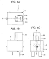
- Figs. 1A to 1C are external views of an electromagnetic relay according to a first exemplary embodiment of the invention, in which Fig. 1A is a plan view thereof, Fig. 1B is a side view thereof, and Fig. 1C is a rear view thereof;
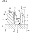
- Fig. 2 is a cross-sectional view of the electromagnetic relay taken along a line II-II shown in Fig. 1 ;
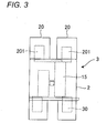
- Fig. 3 is a rear view of an electromagnetic relay according to a second exemplary embodiment of the invention.
- Fig. 4 is a rear view of an electromagnetic relay according to a third exemplary embodiment of the invention.
- Fig. 5 shows that an electromagnetic relay is connected with a connector and an electronic component via a bus bar
- Fig. 6 is external view of a connector integrated electromagnetic relay.
- Figs. 1A to 1C are external views of an electromagnetic relay according to a first exemplary embodiment of the invention.
- Fig. 1A is a view as seen from the upper side (plan view)
- Fig. 1B is a view as seen from the lateral side (side view)
- Fig. 1C is a view as seen from the rear side (rear view).
- An electromagnetic relay 1 of the exemplary embodiment includes a connector 20 and an electronic-component terminal 30.
- the connector 20 is provided on and integrated with an upper surface of a relay body 2, thereby integrated with the relay body 2.
- the electronic-component connection terminal 30 protrudes from a lower surface of the relay body 2.
- the connector 20 includes one terminal 201.
- the terminal 201 and the electronic-component connection terminal 30 are connected to a fixed terminal 15 disposed in the relay body 2.
- the electronic-component connection terminal 30 and the fixed terminal 15 may be configured by a same member or respective separated members.
- the electronic component 102 (see Fig. 5 ) is connected to the electronic-component connection terminal 30.
- Fig. 2 is a cross-sectional view of the electromagnetic relay 1 taken along line II-II shown in Fig. 1 .
- the electromagnetic relay 1 includes a base 10 formed by an insulating member such as a resin.
- the electromagnetic relay 1 further includes an electromagnet unit 11, an armature 12, a card 13, a movable terminal 14, and a fixed terminal 15, which are disposed in parallel on the base 10.
- the electromagnet unit 11 includes a yoke 111 and a coil 112 fixed to the yoke 111.
- the armature 12 is bent into a substantially dogleg shape, and swingably supported via a hinge spring (not shown) by the upper end edge of the yoke 111 of the electromagnet unit 11.
- the card 13 is supported by the base 10 so as to be swingable toward the armature 12 and the movable terminal 14.
- the card 13 has a first branch portion 131 which contacts the armature 12, and a second branch portion 132 which contacts the movable terminal 14.
- the movable terminal 14 is placed so as to oppose the card 13, and an upper end portion thereof contacts the second branch portion 132 of the card 13.
- a movable contact 141 is disposed below a position at which the movable terminal 14 contacts the second branch portion 132 of the card 13.
- the fixed terminal 15 is placed so as to oppose the movable terminal 14, and an upper end portion thereof is formed into an L-shape. A part of the L-shaped portion, which extends in a vertical direction, corresponds to the terminal 201 of the connector 20.
- the electromagnetic relay 1 when no voltage is applied to the electromagnet unit 11, a portion of the armature in the vicinity of a lower end portion 121 is urged by the spring force of the hinge spring (not shown). Therefore, an attractable surface of the upper end portion 122 of the armature 12 is separated from a magnetic pole portion 113 of the electromagnet unit 11. Since the attractable surface of the upper end portion 122 of the armature 12 is separated from the magnetic pole portion 113 of the electromagnet unit 11, the card 13 is in a resting state, and the movable contact 141 of the movable terminal 14 and a fixed contact 151 of the fixed terminal 15 are in a separated state.
- the electromagnet unit 11 When a voltage is applied to the electromagnet unit 11 in this state, the electromagnet unit 11 is in an energized state, and the attractable surface of the upper end portion 122 of the armature 12 is attracted to the electromagnet unit 11. Then, the swinging operation of the armature 12 at this time causes the card 13 to swing toward the movable terminal 14, so that the movable contact 141 of the movable terminal 14 contacts the fixed contact 151 of the fixed terminal 15, whereby the movable terminal 14 and the fixed terminal 15 are in a current conducting state.
- the electromagnet unit 11 In the state in which the voltage is applied to the electromagnet unit 11, when the voltage application is stopped, the electromagnet unit 11 is in a de-energized state, and the attracted force of the armature 12 to the electromagnet unit 11 is released.
- the attracted force of the armature 12 When the attracted force of the armature 12 is released, a part of the armature 12 in the vicinity of the lower end portion 121 is urged by the spring force of the hinge spring (not shown), and the armature 12 swings in the direction opposite to that in the case in which the voltage is applied.
- the swinging operation of the armature 12 at this time causes the card 13 to swing toward the armature 12, so that the movable contact 141 of the movable terminal 14 is separated from the fixed contact 151 of the fixed terminal 15, whereby the movable terminal 14 and the fixed terminal 15 are in a current non-conducting state.
- the connector 20 is provided so as to be integrated with the relay body 2, and the electronic-component connection terminal 30 is disposed so as to protrude from the relay body 2. Therefore, the relay body 2 and the connector 20 can be integrated with each other, and an electronic component can be connected to the electromagnetic relay 1 without using a bus bar.
- one connector 20 is disposed.
- a plurality of connectors may be provided integrally with the relay body 2.
- the electronic-component connection terminal 30 may be disposed for each of a plurality of fixed terminals 15.
- the number of the electronic-component connection terminal 30 is not limited to one, and it is a matter of course that a plurality of electronic-component connection terminals may be disposed.
- Fig. 3 is a rear view (as seen from the rear side) of an electromagnetic relay 3 of the electromagnetic relay 3 according to a second exemplary embodiment.
- two connectors 20 are integrated with the relay body 2, and the terminals 201 of the two connectors 20 are connected to the fixed terminal 15.
- FIG 4 is a rear view (as seen from the rear side) of an electromagnetic relay 4 of the electromagnetic relay 1 according to the third exemplary embodiment.
- two connectors 20 are integrated with the relay body 2, and two electronic-component connection terminals 30 are disposed.
- the terminals 201 of the connectors 20, and the electronic-component connection terminals 30 are connected to two fixed terminals 15, respectively.
- one or more connectors and one or more electronic-component connection terminals may be provided integrally with the relay body, by routing of a main terminal (i.e. fixed terminal 15).
- the connector is integrated with the relay body, and the electronic-component connection terminal protrudes from the relay body. Therefore, the relay body and the connector can be integrated with each other, and an electronic component can be connected to the relay without using a bus bar.
Landscapes
- Physics & Mathematics (AREA)
- Electromagnetism (AREA)
- Switch Cases, Indication, And Locking (AREA)
- Details Of Connecting Devices For Male And Female Coupling (AREA)
- Electromagnets (AREA)
- Coupling Device And Connection With Printed Circuit (AREA)
- Connecting Device With Holders (AREA)
Abstract
Description
- The present invention relates to an electromagnetic relay.
- An electromagnetic relay usually includes a bus bar used for a connection with a connector and an electronic component, as shown in
Fig. 5 . InFig. 5 , anelectromagnetic relay 100 is connected to aconnector 101 and anelectronic component 102 through abus bar 103. As an example of a technique which uses a bus bar for a connection with a connector or an electronic component,JP-A-8-077903 JP-A-8-077903 JP-A-9-219259 - As shown in
Fig. 6 , if arelay body 100 and aconnector 101 are integrated with each other, a bus bar is used only for a connection with an electronic component. When a bus bar is used only for the purpose, the resulting configuration is not desirable from the viewpoint of cost. However, when a bus bar is not used, it is impossible to connect an electronic component to the relay. - The present invention was made in view of the above-described circumstances, and an object thereof is to provide an electromagnetic relay in which a relay body is integrated with a connector and which can be connected to an electronic component without using a bus bar.
- According to an aspect of the invention, there is provided an electromagnetic relay comprising: a relay body; a connector which is integrated with the relay body; and an electronic-component connection terminal which protrudes from the relay body.
-
Figs. 1A to 1C are external views of an electromagnetic relay according to a first exemplary embodiment of the invention, in whichFig. 1A is a plan view thereof,Fig. 1B is a side view thereof, andFig. 1C is a rear view thereof; -
Fig. 2 is a cross-sectional view of the electromagnetic relay taken along a line II-II shown inFig. 1 ; -
Fig. 3 is a rear view of an electromagnetic relay according to a second exemplary embodiment of the invention; -
Fig. 4 is a rear view of an electromagnetic relay according to a third exemplary embodiment of the invention; -
Fig. 5 shows that an electromagnetic relay is connected with a connector and an electronic component via a bus bar; and -
Fig. 6 is external view of a connector integrated electromagnetic relay. - Hereinafter, exemplary embodiments of the invention will be described in detail with reference to the drawings.
-
Figs. 1A to 1C are external views of an electromagnetic relay according to a first exemplary embodiment of the invention.Fig. 1A is a view as seen from the upper side (plan view),Fig. 1B is a view as seen from the lateral side (side view), andFig. 1C is a view as seen from the rear side (rear view). - An
electromagnetic relay 1 of the exemplary embodiment includes aconnector 20 and an electronic-component terminal 30. Theconnector 20 is provided on and integrated with an upper surface of arelay body 2, thereby integrated with therelay body 2. The electronic-component connection terminal 30 protrudes from a lower surface of therelay body 2. Theconnector 20 includes oneterminal 201. Theterminal 201 and the electronic-component connection terminal 30 are connected to afixed terminal 15 disposed in therelay body 2. The electronic-component connection terminal 30 and thefixed terminal 15 may be configured by a same member or respective separated members. The electronic component 102 (seeFig. 5 ) is connected to the electronic-component connection terminal 30. -
Fig. 2 is a cross-sectional view of theelectromagnetic relay 1 taken along line II-II shown inFig. 1 . As shown inFig. 2 , theelectromagnetic relay 1 includes abase 10 formed by an insulating member such as a resin. Theelectromagnetic relay 1 further includes anelectromagnet unit 11, anarmature 12, acard 13, amovable terminal 14, and afixed terminal 15, which are disposed in parallel on thebase 10. - The
electromagnet unit 11 includes ayoke 111 and acoil 112 fixed to theyoke 111. Thearmature 12 is bent into a substantially dogleg shape, and swingably supported via a hinge spring (not shown) by the upper end edge of theyoke 111 of theelectromagnet unit 11. Thecard 13 is supported by thebase 10 so as to be swingable toward thearmature 12 and themovable terminal 14. Thecard 13 has afirst branch portion 131 which contacts thearmature 12, and asecond branch portion 132 which contacts themovable terminal 14. Themovable terminal 14 is placed so as to oppose thecard 13, and an upper end portion thereof contacts thesecond branch portion 132 of thecard 13. In themovable terminal 14, amovable contact 141 is disposed below a position at which themovable terminal 14 contacts thesecond branch portion 132 of thecard 13. Thefixed terminal 15 is placed so as to oppose themovable terminal 14, and an upper end portion thereof is formed into an L-shape. A part of the L-shaped portion, which extends in a vertical direction, corresponds to theterminal 201 of theconnector 20. - In the
electromagnetic relay 1, when no voltage is applied to theelectromagnet unit 11, a portion of the armature in the vicinity of alower end portion 121 is urged by the spring force of the hinge spring (not shown). Therefore, an attractable surface of theupper end portion 122 of thearmature 12 is separated from amagnetic pole portion 113 of theelectromagnet unit 11. Since the attractable surface of theupper end portion 122 of thearmature 12 is separated from themagnetic pole portion 113 of theelectromagnet unit 11, thecard 13 is in a resting state, and themovable contact 141 of themovable terminal 14 and afixed contact 151 of thefixed terminal 15 are in a separated state. When a voltage is applied to theelectromagnet unit 11 in this state, theelectromagnet unit 11 is in an energized state, and the attractable surface of theupper end portion 122 of thearmature 12 is attracted to theelectromagnet unit 11. Then, the swinging operation of thearmature 12 at this time causes thecard 13 to swing toward themovable terminal 14, so that themovable contact 141 of themovable terminal 14 contacts thefixed contact 151 of thefixed terminal 15, whereby themovable terminal 14 and thefixed terminal 15 are in a current conducting state. - In the state in which the voltage is applied to the
electromagnet unit 11, when the voltage application is stopped, theelectromagnet unit 11 is in a de-energized state, and the attracted force of thearmature 12 to theelectromagnet unit 11 is released. When the attracted force of thearmature 12 is released, a part of thearmature 12 in the vicinity of thelower end portion 121 is urged by the spring force of the hinge spring (not shown), and thearmature 12 swings in the direction opposite to that in the case in which the voltage is applied. The swinging operation of thearmature 12 at this time causes thecard 13 to swing toward thearmature 12, so that themovable contact 141 of themovable terminal 14 is separated from thefixed contact 151 of thefixed terminal 15, whereby themovable terminal 14 and thefixed terminal 15 are in a current non-conducting state. - As described above, according to the
electromagnetic relay 1 of the first exemplary embodiment, theconnector 20 is provided so as to be integrated with therelay body 2, and the electronic-component connection terminal 30 is disposed so as to protrude from therelay body 2. Therefore, therelay body 2 and theconnector 20 can be integrated with each other, and an electronic component can be connected to theelectromagnetic relay 1 without using a bus bar. - In the
electromagnetic relay 1 of the exemplary embodiment, oneconnector 20 is disposed. Alternatively, a plurality of connectors may be provided integrally with therelay body 2. Furthermore, the electronic-component connection terminal 30 may be disposed for each of a plurality of fixedterminals 15. The number of the electronic-component connection terminal 30 is not limited to one, and it is a matter of course that a plurality of electronic-component connection terminals may be disposed.Fig. 3 is a rear view (as seen from the rear side) of anelectromagnetic relay 3 of theelectromagnetic relay 3 according to a second exemplary embodiment. In the second exemplary embodiment, twoconnectors 20 are integrated with therelay body 2, and theterminals 201 of the twoconnectors 20 are connected to the fixedterminal 15.Fig. 4 is a rear view (as seen from the rear side) of anelectromagnetic relay 4 of theelectromagnetic relay 1 according to the third exemplary embodiment. In the third exemplary embodiment, twoconnectors 20 are integrated with therelay body 2, and two electronic-component connection terminals 30 are disposed. In the exemplary embodiment, theterminals 201 of theconnectors 20, and the electronic-component connection terminals 30 are connected to two fixedterminals 15, respectively. - Further, as shown in
Fig. 4 , one or more connectors and one or more electronic-component connection terminals, a total number of which is a maximum of four, may be provided integrally with the relay body, by routing of a main terminal (i.e. fixed terminal 15). - According to the exemplary embodiments of the invention, the connector is integrated with the relay body, and the electronic-component connection terminal protrudes from the relay body. Therefore, the relay body and the connector can be integrated with each other, and an electronic component can be connected to the relay without using a bus bar.
Claims (3)
- An electromagnetic relay comprising:a relay body;a connector which is integrated with the relay body; andan electronic-component connection terminal which protrudes from the relay body.
- The electromagnetic relay according to claim 1, wherein one or more connectors and one or more electronic-component connection terminals, a total number of which is a maximum of four, are provided integrally with the relay body, by routing of a main terminal.
- The electromagnetic relay according to claim 1 or 2,
wherein the connector comprises a connection terminal,
wherein the relay body comprises:a base comprising an upper surface and a lower surface opposite to the upper surface;an electromagnet unit which is provided on the upper surface of the base and which comprises a yoke and a coil fixed to the yoke;an armature swingably supported by the yoke;a card which is provided on the upper surface of the base so as to be swingable and which comprises a first branch portion contacting the armature and a second branch portion;a movable terminal provided on the upper surface of the base so as to contact the second branch portion of the card; anda fixed terminal which opposes the movable terminal and which comprises an upper end and a lower end opposite to the upper end,wherein the upper end of the fixed terminal is connected to the connection terminal of the connector, and the lower end of the fixed terminal is connected to the electronic-component connection terminal, and
wherein the electronic-component connection terminal protrudes from the lower surface of the base.
Applications Claiming Priority (1)
| Application Number | Priority Date | Filing Date | Title |
|---|---|---|---|
| JP2011063972A JP5807174B2 (en) | 2011-03-23 | 2011-03-23 | Electromagnetic relay |
Publications (2)
| Publication Number | Publication Date |
|---|---|
| EP2503582A1 true EP2503582A1 (en) | 2012-09-26 |
| EP2503582B1 EP2503582B1 (en) | 2013-12-11 |
Family
ID=45939087
Family Applications (1)
| Application Number | Title | Priority Date | Filing Date |
|---|---|---|---|
| EP12001944.3A Active EP2503582B1 (en) | 2011-03-23 | 2012-03-20 | Electromagnetic relay |
Country Status (6)
| Country | Link |
|---|---|
| US (1) | US8810342B2 (en) |
| EP (1) | EP2503582B1 (en) |
| JP (1) | JP5807174B2 (en) |
| KR (1) | KR20120109321A (en) |
| CN (1) | CN102693875B (en) |
| ES (1) | ES2440342T3 (en) |
Families Citing this family (3)
| Publication number | Priority date | Publication date | Assignee | Title |
|---|---|---|---|---|
| JP2014165152A (en) * | 2013-02-27 | 2014-09-08 | Fujitsu Component Ltd | Electromagnetic relay |
| JP6341361B2 (en) * | 2013-12-13 | 2018-06-13 | パナソニックIpマネジメント株式会社 | Electromagnetic relay |
| CN108321032B (en) * | 2018-03-13 | 2024-01-26 | 厦门宏发电声股份有限公司 | Movable contact spring for safety relay and safety relay thereof |
Citations (6)
| Publication number | Priority date | Publication date | Assignee | Title |
|---|---|---|---|---|
| EP0177349A2 (en) * | 1984-10-03 | 1986-04-09 | Honda Giken Kogyo Kabushiki Kaisha | Fuse circuit unit |
| EP0243979A2 (en) * | 1986-05-02 | 1987-11-04 | Hengstler Bauelemente GmbH | Miniature electromagnetic relay |
| JPH0877903A (en) | 1994-06-27 | 1996-03-22 | Anden Kk | Relay device and its manufacture |
| DE29612042U1 (en) * | 1996-07-10 | 1996-09-05 | Siemens AG, 80333 München | Control module for a relay and its arrangement with a relay |
| JPH09219259A (en) | 1996-02-09 | 1997-08-19 | Yazaki Corp | Relay built-in connector |
| FR2909219A1 (en) * | 2006-11-29 | 2008-05-30 | Denso Corp | ELECTROMAGNETIC SWITCH FOR USE IN A STARTER. |
Family Cites Families (11)
| Publication number | Priority date | Publication date | Assignee | Title |
|---|---|---|---|---|
| DE3209915A1 (en) * | 1982-03-18 | 1983-09-22 | SWF-Spezialfabrik für Autozubehör Gustav Rau GmbH, 7120 Bietigheim-Bissingen | Electrical relay, especially for motor vehicles |
| JP2893601B2 (en) * | 1989-11-09 | 1999-05-24 | オムロン株式会社 | Electromagnetic relay |
| DE69018720T2 (en) * | 1989-07-20 | 1995-12-21 | Omron Tateisi Electronics Co | Connection contact form for electromagnetic relay. |
| KR930000794B1 (en) | 1990-09-22 | 1993-02-04 | 신성전자 산업사 | Crimped Phone Flock |
| US6133812A (en) * | 1998-05-21 | 2000-10-17 | Relcomm Technologies, Inc. | Switching relay with magnetically resettable actuator mechanism |
| JP2002343213A (en) * | 2001-05-18 | 2002-11-29 | Daiichi Denki Kk | Small relay |
| CA2365551C (en) * | 2001-12-19 | 2005-07-26 | Electroline Equipment Inc. | Circuit board connectable rf relay |
| JP4168733B2 (en) | 2002-11-12 | 2008-10-22 | オムロン株式会社 | Electromagnetic relay |
| KR100627432B1 (en) | 2004-06-28 | 2006-09-25 | 타이코에이엠피 주식회사 | Relay connection device |
| CN100588034C (en) * | 2008-04-01 | 2010-02-03 | 何岳明 | A junction unit and a junction box using the junction unit |
| CN201527937U (en) * | 2009-11-03 | 2010-07-14 | 宁波金海电子有限公司 | Multifunctional electromagnetic relay with small volume |
-
2011
- 2011-03-23 JP JP2011063972A patent/JP5807174B2/en not_active Expired - Fee Related
-
2012
- 2012-03-16 KR KR1020120027187A patent/KR20120109321A/en not_active Ceased
- 2012-03-20 ES ES12001944.3T patent/ES2440342T3/en active Active
- 2012-03-20 EP EP12001944.3A patent/EP2503582B1/en active Active
- 2012-03-21 CN CN201210075194.2A patent/CN102693875B/en active Active
- 2012-03-22 US US13/427,300 patent/US8810342B2/en active Active
Patent Citations (6)
| Publication number | Priority date | Publication date | Assignee | Title |
|---|---|---|---|---|
| EP0177349A2 (en) * | 1984-10-03 | 1986-04-09 | Honda Giken Kogyo Kabushiki Kaisha | Fuse circuit unit |
| EP0243979A2 (en) * | 1986-05-02 | 1987-11-04 | Hengstler Bauelemente GmbH | Miniature electromagnetic relay |
| JPH0877903A (en) | 1994-06-27 | 1996-03-22 | Anden Kk | Relay device and its manufacture |
| JPH09219259A (en) | 1996-02-09 | 1997-08-19 | Yazaki Corp | Relay built-in connector |
| DE29612042U1 (en) * | 1996-07-10 | 1996-09-05 | Siemens AG, 80333 München | Control module for a relay and its arrangement with a relay |
| FR2909219A1 (en) * | 2006-11-29 | 2008-05-30 | Denso Corp | ELECTROMAGNETIC SWITCH FOR USE IN A STARTER. |
Also Published As
| Publication number | Publication date |
|---|---|
| JP2012199195A (en) | 2012-10-18 |
| KR20120109321A (en) | 2012-10-08 |
| EP2503582B1 (en) | 2013-12-11 |
| CN102693875A (en) | 2012-09-26 |
| ES2440342T3 (en) | 2014-01-28 |
| US20120242432A1 (en) | 2012-09-27 |
| CN102693875B (en) | 2016-01-20 |
| JP5807174B2 (en) | 2015-11-10 |
| US8810342B2 (en) | 2014-08-19 |
Similar Documents
| Publication | Publication Date | Title |
|---|---|---|
| US9431182B2 (en) | Double contact point switch and a magnetic connector having the double contact point switch | |
| CN109727819B (en) | Electromagnetic Relay | |
| US9305718B2 (en) | Electromagnetic relay | |
| US10163588B2 (en) | Electromagnetic relay including yoke-retaining bottom plate | |
| US8305166B2 (en) | Electromagnetic relay | |
| EP2551868B1 (en) | Contact device and electromagnetic relay including same | |
| CN102891039A (en) | Relay | |
| CN102222588A (en) | Electromagnetic relay | |
| JP4697308B2 (en) | Mounting detection structure for small electrical equipment | |
| EP2919252A1 (en) | Electromagnetic relay | |
| US8664553B2 (en) | Switch device and connector | |
| EP2503582B1 (en) | Electromagnetic relay | |
| US8050008B2 (en) | Relay device | |
| US20160086755A1 (en) | Electromagnetic relay | |
| CN109818213A (en) | Connector Assemblies and Electronics | |
| CN111527579A (en) | Electromagnetic relay | |
| CN104851750B (en) | Electromagnetic relay | |
| JP2005222946A (en) | Electromagnetic relay and receptacle | |
| CN105745795B (en) | Relay Connector Assemblies for Relay Systems | |
| CN104795281B (en) | A kind of electromagnetic relay | |
| CN112509876B (en) | Electromagnetic relay | |
| CN206541784U (en) | Breaker of plastic casing | |
| EP3047498B1 (en) | Active electrical component | |
| CN109217068B (en) | Manufacturing process of card connector switch terminal | |
| JP6830259B2 (en) | Electromagnetic relay |
Legal Events
| Date | Code | Title | Description |
|---|---|---|---|
| PUAI | Public reference made under article 153(3) epc to a published international application that has entered the european phase |
Free format text: ORIGINAL CODE: 0009012 |
|
| AK | Designated contracting states |
Kind code of ref document: A1 Designated state(s): AL AT BE BG CH CY CZ DE DK EE ES FI FR GB GR HR HU IE IS IT LI LT LU LV MC MK MT NL NO PL PT RO RS SE SI SK SM TR |
|
| AX | Request for extension of the european patent |
Extension state: BA ME |
|
| 17P | Request for examination filed |
Effective date: 20130326 |
|
| GRAP | Despatch of communication of intention to grant a patent |
Free format text: ORIGINAL CODE: EPIDOSNIGR1 |
|
| GRAJ | Information related to disapproval of communication of intention to grant by the applicant or resumption of examination proceedings by the epo deleted |
Free format text: ORIGINAL CODE: EPIDOSDIGR1 |
|
| GRAP | Despatch of communication of intention to grant a patent |
Free format text: ORIGINAL CODE: EPIDOSNIGR1 |
|
| INTG | Intention to grant announced |
Effective date: 20130621 |
|
| INTG | Intention to grant announced |
Effective date: 20130704 |
|
| GRAS | Grant fee paid |
Free format text: ORIGINAL CODE: EPIDOSNIGR3 |
|
| GRAA | (expected) grant |
Free format text: ORIGINAL CODE: 0009210 |
|
| AK | Designated contracting states |
Kind code of ref document: B1 Designated state(s): AL AT BE BG CH CY CZ DE DK EE ES FI FR GB GR HR HU IE IS IT LI LT LU LV MC MK MT NL NO PL PT RO RS SE SI SK SM TR |
|
| REG | Reference to a national code |
Ref country code: GB Ref legal event code: FG4D |
|
| REG | Reference to a national code |
Ref country code: CH Ref legal event code: EP |
|
| REG | Reference to a national code |
Ref country code: AT Ref legal event code: REF Ref document number: 644961 Country of ref document: AT Kind code of ref document: T Effective date: 20140115 |
|
| REG | Reference to a national code |
Ref country code: ES Ref legal event code: FG2A Ref document number: 2440342 Country of ref document: ES Kind code of ref document: T3 Effective date: 20140128 |
|
| REG | Reference to a national code |
Ref country code: IE Ref legal event code: FG4D |
|
| REG | Reference to a national code |
Ref country code: DE Ref legal event code: R096 Ref document number: 602012000619 Country of ref document: DE Effective date: 20140206 |
|
| REG | Reference to a national code |
Ref country code: NL Ref legal event code: T3 |
|
| REG | Reference to a national code |
Ref country code: SE Ref legal event code: TRGR |
|
| REG | Reference to a national code |
Ref country code: AT Ref legal event code: MK05 Ref document number: 644961 Country of ref document: AT Kind code of ref document: T Effective date: 20131211 |
|
| PG25 | Lapsed in a contracting state [announced via postgrant information from national office to epo] |
Ref country code: HR Free format text: LAPSE BECAUSE OF FAILURE TO SUBMIT A TRANSLATION OF THE DESCRIPTION OR TO PAY THE FEE WITHIN THE PRESCRIBED TIME-LIMIT Effective date: 20131211 Ref country code: FI Free format text: LAPSE BECAUSE OF FAILURE TO SUBMIT A TRANSLATION OF THE DESCRIPTION OR TO PAY THE FEE WITHIN THE PRESCRIBED TIME-LIMIT Effective date: 20131211 Ref country code: NO Free format text: LAPSE BECAUSE OF FAILURE TO SUBMIT A TRANSLATION OF THE DESCRIPTION OR TO PAY THE FEE WITHIN THE PRESCRIBED TIME-LIMIT Effective date: 20140311 Ref country code: LT Free format text: LAPSE BECAUSE OF FAILURE TO SUBMIT A TRANSLATION OF THE DESCRIPTION OR TO PAY THE FEE WITHIN THE PRESCRIBED TIME-LIMIT Effective date: 20131211 |
|
| REG | Reference to a national code |
Ref country code: LT Ref legal event code: MG4D |
|
| PG25 | Lapsed in a contracting state [announced via postgrant information from national office to epo] |
Ref country code: AT Free format text: LAPSE BECAUSE OF FAILURE TO SUBMIT A TRANSLATION OF THE DESCRIPTION OR TO PAY THE FEE WITHIN THE PRESCRIBED TIME-LIMIT Effective date: 20131211 Ref country code: CY Free format text: LAPSE BECAUSE OF FAILURE TO SUBMIT A TRANSLATION OF THE DESCRIPTION OR TO PAY THE FEE WITHIN THE PRESCRIBED TIME-LIMIT Effective date: 20131211 Ref country code: LV Free format text: LAPSE BECAUSE OF FAILURE TO SUBMIT A TRANSLATION OF THE DESCRIPTION OR TO PAY THE FEE WITHIN THE PRESCRIBED TIME-LIMIT Effective date: 20131211 Ref country code: RS Free format text: LAPSE BECAUSE OF FAILURE TO SUBMIT A TRANSLATION OF THE DESCRIPTION OR TO PAY THE FEE WITHIN THE PRESCRIBED TIME-LIMIT Effective date: 20131211 |
|
| PG25 | Lapsed in a contracting state [announced via postgrant information from national office to epo] |
Ref country code: EE Free format text: LAPSE BECAUSE OF FAILURE TO SUBMIT A TRANSLATION OF THE DESCRIPTION OR TO PAY THE FEE WITHIN THE PRESCRIBED TIME-LIMIT Effective date: 20131211 Ref country code: IS Free format text: LAPSE BECAUSE OF FAILURE TO SUBMIT A TRANSLATION OF THE DESCRIPTION OR TO PAY THE FEE WITHIN THE PRESCRIBED TIME-LIMIT Effective date: 20140411 Ref country code: BE Free format text: LAPSE BECAUSE OF FAILURE TO SUBMIT A TRANSLATION OF THE DESCRIPTION OR TO PAY THE FEE WITHIN THE PRESCRIBED TIME-LIMIT Effective date: 20131211 |
|
| PG25 | Lapsed in a contracting state [announced via postgrant information from national office to epo] |
Ref country code: PL Free format text: LAPSE BECAUSE OF FAILURE TO SUBMIT A TRANSLATION OF THE DESCRIPTION OR TO PAY THE FEE WITHIN THE PRESCRIBED TIME-LIMIT Effective date: 20131211 Ref country code: RO Free format text: LAPSE BECAUSE OF FAILURE TO SUBMIT A TRANSLATION OF THE DESCRIPTION OR TO PAY THE FEE WITHIN THE PRESCRIBED TIME-LIMIT Effective date: 20131211 Ref country code: CZ Free format text: LAPSE BECAUSE OF FAILURE TO SUBMIT A TRANSLATION OF THE DESCRIPTION OR TO PAY THE FEE WITHIN THE PRESCRIBED TIME-LIMIT Effective date: 20131211 Ref country code: SK Free format text: LAPSE BECAUSE OF FAILURE TO SUBMIT A TRANSLATION OF THE DESCRIPTION OR TO PAY THE FEE WITHIN THE PRESCRIBED TIME-LIMIT Effective date: 20131211 Ref country code: PT Free format text: LAPSE BECAUSE OF FAILURE TO SUBMIT A TRANSLATION OF THE DESCRIPTION OR TO PAY THE FEE WITHIN THE PRESCRIBED TIME-LIMIT Effective date: 20140411 |
|
| REG | Reference to a national code |
Ref country code: DE Ref legal event code: R097 Ref document number: 602012000619 Country of ref document: DE |
|
| PLBE | No opposition filed within time limit |
Free format text: ORIGINAL CODE: 0009261 |
|
| STAA | Information on the status of an ep patent application or granted ep patent |
Free format text: STATUS: NO OPPOSITION FILED WITHIN TIME LIMIT |
|
| PG25 | Lapsed in a contracting state [announced via postgrant information from national office to epo] |
Ref country code: DK Free format text: LAPSE BECAUSE OF FAILURE TO SUBMIT A TRANSLATION OF THE DESCRIPTION OR TO PAY THE FEE WITHIN THE PRESCRIBED TIME-LIMIT Effective date: 20131211 Ref country code: LU Free format text: LAPSE BECAUSE OF FAILURE TO SUBMIT A TRANSLATION OF THE DESCRIPTION OR TO PAY THE FEE WITHIN THE PRESCRIBED TIME-LIMIT Effective date: 20140320 |
|
| 26N | No opposition filed |
Effective date: 20140912 |
|
| REG | Reference to a national code |
Ref country code: DE Ref legal event code: R097 Ref document number: 602012000619 Country of ref document: DE Effective date: 20140912 |
|
| REG | Reference to a national code |
Ref country code: IE Ref legal event code: MM4A |
|
| PG25 | Lapsed in a contracting state [announced via postgrant information from national office to epo] |
Ref country code: IE Free format text: LAPSE BECAUSE OF NON-PAYMENT OF DUE FEES Effective date: 20140320 |
|
| PG25 | Lapsed in a contracting state [announced via postgrant information from national office to epo] |
Ref country code: SI Free format text: LAPSE BECAUSE OF FAILURE TO SUBMIT A TRANSLATION OF THE DESCRIPTION OR TO PAY THE FEE WITHIN THE PRESCRIBED TIME-LIMIT Effective date: 20131211 |
|
| REG | Reference to a national code |
Ref country code: CH Ref legal event code: PL |
|
| PG25 | Lapsed in a contracting state [announced via postgrant information from national office to epo] |
Ref country code: LI Free format text: LAPSE BECAUSE OF NON-PAYMENT OF DUE FEES Effective date: 20150331 Ref country code: CH Free format text: LAPSE BECAUSE OF NON-PAYMENT OF DUE FEES Effective date: 20150331 |
|
| REG | Reference to a national code |
Ref country code: FR Ref legal event code: PLFP Year of fee payment: 5 |
|
| PG25 | Lapsed in a contracting state [announced via postgrant information from national office to epo] |
Ref country code: MT Free format text: LAPSE BECAUSE OF FAILURE TO SUBMIT A TRANSLATION OF THE DESCRIPTION OR TO PAY THE FEE WITHIN THE PRESCRIBED TIME-LIMIT Effective date: 20131211 |
|
| PG25 | Lapsed in a contracting state [announced via postgrant information from national office to epo] |
Ref country code: SM Free format text: LAPSE BECAUSE OF FAILURE TO SUBMIT A TRANSLATION OF THE DESCRIPTION OR TO PAY THE FEE WITHIN THE PRESCRIBED TIME-LIMIT Effective date: 20131211 |
|
| PGFP | Annual fee paid to national office [announced via postgrant information from national office to epo] |
Ref country code: ES Payment date: 20160211 Year of fee payment: 5 |
|
| PG25 | Lapsed in a contracting state [announced via postgrant information from national office to epo] |
Ref country code: MC Free format text: LAPSE BECAUSE OF FAILURE TO SUBMIT A TRANSLATION OF THE DESCRIPTION OR TO PAY THE FEE WITHIN THE PRESCRIBED TIME-LIMIT Effective date: 20131211 |
|
| PGFP | Annual fee paid to national office [announced via postgrant information from national office to epo] |
Ref country code: SE Payment date: 20160311 Year of fee payment: 5 Ref country code: NL Payment date: 20160210 Year of fee payment: 5 Ref country code: FR Payment date: 20160208 Year of fee payment: 5 Ref country code: GB Payment date: 20160316 Year of fee payment: 5 |
|
| PG25 | Lapsed in a contracting state [announced via postgrant information from national office to epo] |
Ref country code: GR Free format text: LAPSE BECAUSE OF FAILURE TO SUBMIT A TRANSLATION OF THE DESCRIPTION OR TO PAY THE FEE WITHIN THE PRESCRIBED TIME-LIMIT Effective date: 20140312 Ref country code: BG Free format text: LAPSE BECAUSE OF FAILURE TO SUBMIT A TRANSLATION OF THE DESCRIPTION OR TO PAY THE FEE WITHIN THE PRESCRIBED TIME-LIMIT Effective date: 20131211 |
|
| PG25 | Lapsed in a contracting state [announced via postgrant information from national office to epo] |
Ref country code: HU Free format text: LAPSE BECAUSE OF FAILURE TO SUBMIT A TRANSLATION OF THE DESCRIPTION OR TO PAY THE FEE WITHIN THE PRESCRIBED TIME-LIMIT; INVALID AB INITIO Effective date: 20120320 Ref country code: TR Free format text: LAPSE BECAUSE OF FAILURE TO SUBMIT A TRANSLATION OF THE DESCRIPTION OR TO PAY THE FEE WITHIN THE PRESCRIBED TIME-LIMIT Effective date: 20131211 |
|
| PGFP | Annual fee paid to national office [announced via postgrant information from national office to epo] |
Ref country code: IT Payment date: 20160324 Year of fee payment: 5 |
|
| REG | Reference to a national code |
Ref country code: SE Ref legal event code: EUG |
|
| REG | Reference to a national code |
Ref country code: NL Ref legal event code: MM Effective date: 20170401 |
|
| GBPC | Gb: european patent ceased through non-payment of renewal fee |
Effective date: 20170320 |
|
| PG25 | Lapsed in a contracting state [announced via postgrant information from national office to epo] |
Ref country code: SE Free format text: LAPSE BECAUSE OF NON-PAYMENT OF DUE FEES Effective date: 20170321 |
|
| REG | Reference to a national code |
Ref country code: FR Ref legal event code: ST Effective date: 20171130 |
|
| PG25 | Lapsed in a contracting state [announced via postgrant information from national office to epo] |
Ref country code: NL Free format text: LAPSE BECAUSE OF NON-PAYMENT OF DUE FEES Effective date: 20170401 Ref country code: FR Free format text: LAPSE BECAUSE OF NON-PAYMENT OF DUE FEES Effective date: 20170331 |
|
| PG25 | Lapsed in a contracting state [announced via postgrant information from national office to epo] |
Ref country code: GB Free format text: LAPSE BECAUSE OF NON-PAYMENT OF DUE FEES Effective date: 20170320 Ref country code: IT Free format text: LAPSE BECAUSE OF NON-PAYMENT OF DUE FEES Effective date: 20170320 |
|
| REG | Reference to a national code |
Ref country code: ES Ref legal event code: FD2A Effective date: 20180622 |
|
| PG25 | Lapsed in a contracting state [announced via postgrant information from national office to epo] |
Ref country code: MK Free format text: LAPSE BECAUSE OF FAILURE TO SUBMIT A TRANSLATION OF THE DESCRIPTION OR TO PAY THE FEE WITHIN THE PRESCRIBED TIME-LIMIT Effective date: 20131211 |
|
| PG25 | Lapsed in a contracting state [announced via postgrant information from national office to epo] |
Ref country code: ES Free format text: LAPSE BECAUSE OF NON-PAYMENT OF DUE FEES Effective date: 20170321 |
|
| PG25 | Lapsed in a contracting state [announced via postgrant information from national office to epo] |
Ref country code: AL Free format text: LAPSE BECAUSE OF FAILURE TO SUBMIT A TRANSLATION OF THE DESCRIPTION OR TO PAY THE FEE WITHIN THE PRESCRIBED TIME-LIMIT Effective date: 20131211 |
|
| PGFP | Annual fee paid to national office [announced via postgrant information from national office to epo] |
Ref country code: DE Payment date: 20241231 Year of fee payment: 14 |