EP2757396B1 - Fiber stabilization of optical path differences (OPD) over a wide bandwidth frequency range for extended periods of time - Google Patents
Fiber stabilization of optical path differences (OPD) over a wide bandwidth frequency range for extended periods of time Download PDFInfo
- Publication number
- EP2757396B1 EP2757396B1 EP14150572.7A EP14150572A EP2757396B1 EP 2757396 B1 EP2757396 B1 EP 2757396B1 EP 14150572 A EP14150572 A EP 14150572A EP 2757396 B1 EP2757396 B1 EP 2757396B1
- Authority
- EP
- European Patent Office
- Prior art keywords
- optical
- signal
- telescope
- fiber
- optical beam
- Prior art date
- Legal status (The legal status is an assumption and is not a legal conclusion. Google has not performed a legal analysis and makes no representation as to the accuracy of the status listed.)
- Active
Links
- 230000003287 optical effect Effects 0.000 title claims description 254
- 239000000835 fiber Substances 0.000 title claims description 89
- 230000006641 stabilisation Effects 0.000 title claims description 18
- 238000011105 stabilization Methods 0.000 title claims description 18
- 238000000034 method Methods 0.000 claims description 47
- 238000013519 translation Methods 0.000 claims description 30
- 238000001914 filtration Methods 0.000 claims description 6
- 238000011045 prefiltration Methods 0.000 claims description 4
- 239000013307 optical fiber Substances 0.000 description 22
- 230000000694 effects Effects 0.000 description 7
- 238000010586 diagram Methods 0.000 description 6
- 238000003384 imaging method Methods 0.000 description 6
- 230000008901 benefit Effects 0.000 description 4
- 238000013461 design Methods 0.000 description 4
- 239000006185 dispersion Substances 0.000 description 4
- 230000010287 polarization Effects 0.000 description 4
- 238000012545 processing Methods 0.000 description 3
- 230000008569 process Effects 0.000 description 2
- 230000035945 sensitivity Effects 0.000 description 2
- 230000001427 coherent effect Effects 0.000 description 1
- 238000012937 correction Methods 0.000 description 1
- 238000011161 development Methods 0.000 description 1
- 230000007613 environmental effect Effects 0.000 description 1
- 238000002474 experimental method Methods 0.000 description 1
- 230000007774 longterm Effects 0.000 description 1
- 238000012986 modification Methods 0.000 description 1
- 230000004048 modification Effects 0.000 description 1
- 230000009467 reduction Effects 0.000 description 1
- 238000005070 sampling Methods 0.000 description 1
- 238000010561 standard procedure Methods 0.000 description 1
Images


Classifications
-
- G—PHYSICS
- G01—MEASURING; TESTING
- G01B—MEASURING LENGTH, THICKNESS OR SIMILAR LINEAR DIMENSIONS; MEASURING ANGLES; MEASURING AREAS; MEASURING IRREGULARITIES OF SURFACES OR CONTOURS
- G01B9/00—Measuring instruments characterised by the use of optical techniques
- G01B9/02—Interferometers
-
- G—PHYSICS
- G02—OPTICS
- G02B—OPTICAL ELEMENTS, SYSTEMS OR APPARATUS
- G02B26/00—Optical devices or arrangements for the control of light using movable or deformable optical elements
- G02B26/08—Optical devices or arrangements for the control of light using movable or deformable optical elements for controlling the direction of light
- G02B26/0816—Optical devices or arrangements for the control of light using movable or deformable optical elements for controlling the direction of light by means of one or more reflecting elements
-
- G—PHYSICS
- G01—MEASURING; TESTING
- G01B—MEASURING LENGTH, THICKNESS OR SIMILAR LINEAR DIMENSIONS; MEASURING ANGLES; MEASURING AREAS; MEASURING IRREGULARITIES OF SURFACES OR CONTOURS
- G01B9/00—Measuring instruments characterised by the use of optical techniques
- G01B9/02—Interferometers
- G01B9/02055—Reduction or prevention of errors; Testing; Calibration
- G01B9/02062—Active error reduction, i.e. varying with time
- G01B9/02067—Active error reduction, i.e. varying with time by electronic control systems, i.e. using feedback acting on optics or light
-
- G—PHYSICS
- G02—OPTICS
- G02B—OPTICAL ELEMENTS, SYSTEMS OR APPARATUS
- G02B6/00—Light guides; Structural details of arrangements comprising light guides and other optical elements, e.g. couplings
- G02B6/24—Coupling light guides
- G02B6/26—Optical coupling means
- G02B6/28—Optical coupling means having data bus means, i.e. plural waveguides interconnected and providing an inherently bidirectional system by mixing and splitting signals
- G02B6/293—Optical coupling means having data bus means, i.e. plural waveguides interconnected and providing an inherently bidirectional system by mixing and splitting signals with wavelength selective means
-
- G—PHYSICS
- G01—MEASURING; TESTING
- G01B—MEASURING LENGTH, THICKNESS OR SIMILAR LINEAR DIMENSIONS; MEASURING ANGLES; MEASURING AREAS; MEASURING IRREGULARITIES OF SURFACES OR CONTOURS
- G01B2290/00—Aspects of interferometers not specifically covered by any group under G01B9/02
- G01B2290/10—Astronomic interferometers
-
- Y—GENERAL TAGGING OF NEW TECHNOLOGICAL DEVELOPMENTS; GENERAL TAGGING OF CROSS-SECTIONAL TECHNOLOGIES SPANNING OVER SEVERAL SECTIONS OF THE IPC; TECHNICAL SUBJECTS COVERED BY FORMER USPC CROSS-REFERENCE ART COLLECTIONS [XRACs] AND DIGESTS
- Y10—TECHNICAL SUBJECTS COVERED BY FORMER USPC
- Y10S—TECHNICAL SUBJECTS COVERED BY FORMER USPC CROSS-REFERENCE ART COLLECTIONS [XRACs] AND DIGESTS
- Y10S359/00—Optical: systems and elements
- Y10S359/90—Methods
Definitions
- the present disclosure relates to fiber stabilization of optical path differences (OPD).
- OPD optical path differences
- the present disclosure relates to fiber stabilization of OPD over a wide bandwidth frequency range for extended periods of time.
- the present disclosure relates to a method, system, and apparatus for fiber stabilization of OPD over a wide bandwidth frequency range for extended periods of time.
- the present disclosure teaches a method for fiber stabilization of OPD.
- the disclosed method involves radiating, by a laser, an optical beam.
- the method further involves splitting, by a beam splitter, the optical beam into a first optical beam and a second optical beam.
- the method involves circulating, by a first circulator, the first optical beam through a fiber stretcher to a translation stage of an adjustable optical telescope.
- the method involves reflecting, by a first mirror on the translation stage, the first optical beam.
- the method involves circulating, by the first circulator, a first circulated beam, which comprises the first optical beam and an adjustable optical telescope beam, to a first dichroic beam splitter. Also, the method involves splitting, by the first dichroic beam splitter, the first circulated beam into the first optical beam and the adjustable optical telescope beam. In addition, the method involves circulating, by a second circulator, the second optical beam to a reference optical telescope. Additionally, the method involves reflecting, by a second mirror, the second optical beam. In addition, the method involves circulating, by the second circulator, a second circulated beam, which comprises the second optical beam and a reference optical telescope beam, to a second dichroic beam splitter. Also, the method involves splitting, by the second dichroic beam splitter, the second circulated beam into the second optical beam and the reference optical telescope beam.
- the method may involve inputting, into an interferometer, the first optical beam and the second optical beam.
- the method may involve outputting, from the interferometer, an in-phase signal and a quadrature signal, which together form a sinusoidal signal.
- the method may involve filtering, by at least one processor, the sinusoidal signal to form a wide bandwidth signal, which contains a high frequency signal, and a low frequency signal.
- the method may further involve controlling, with a stage controller, the translation stage by using the low frequency signal.
- the method may involve controlling, with a fiber stretcher controller, the fiber stretcher by using the high frequency signal.
- the method may further involve inputting, into a telescope light receiving interferometer, the adjustable optical telescope beam and the reference optical telescope beam, to produce a binocular image.
- the interferometer may be a Michelson interferometer.
- the method further involves amplifying with a first amplifier the in-phase signal, and amplifying with a second amplifier the quadrature signal.
- the method may further involve prefiltering, with a filter buffer card, the in-phase signal and the quadrature signal to be within at least one predetermined frequency band.
- the fiber stretcher controller may be a fiber stretcher power supply.
- the filtering of the sinusoidal signal to form a high frequency signal and a low frequency signal may be performed by integrating the sinusoidal signal.
- the stage controller may be a piezo electric controller.
- a system for fiber stabilization of OPD may involve a laser to radiate an optical beam.
- the system may further involve a beam splitter to split the optical beam into a first optical beam and a second optical beam.
- the system may involve a first circulator to circulate the first optical beam through a fiber stretcher to a translation stage of an adjustable optical telescope, and to circulate a first circulated beam, which comprises the first optical beam and an adjustable optical telescope beam, to a first dichroic beam splitter.
- the system may involve a first mirror, on the translation stage, to reflect the first optical beam.
- the system may involve the first dichroic beam splitter to split the first circulated beam into the first optical beam and the adjustable optical telescope beam.
- the system may involve a second circulator to circulate the second optical beam to a reference optical telescope, and to circulate a second circulated beam, which comprises the second optical beam and a reference optical telescope beam, to a second dichroic beam splitter.
- the system may involve a second mirror to reflect the second optical beam.
- the system may involve the second dichroic beam splitter to split the second circulated beam into the second optical beam and the reference optical telescope beam.
- the system may involve an interferometer to receive the first optical beam and the second optical beam, and to output an in-phase signal and a quadrature signal, which together form a sinusoidal signal.
- the system may involve at least one processor to filter the sinusoidal signal to form a high frequency signal and a low frequency signal.
- the system may involve a stage controller to control the translation stage by using the low frequency signal.
- the system may involve a fiber stretcher controller to control the fiber stretcher by using the high frequency signal.
- the system may further involve a telescope light receiving interferometer to receive the adjustable optical telescope beam and the reference optical telescope beam, and to produce a binocular image.
- the system may further involve a first amplifier to amplify the in-phase signal, and a second amplifier to amplify the quadrature signal.
- the system may further involve a filter buffer card to prefilter the in-phase signal and the quadrature signal to be within at least one predetermined frequency band.
- At least one processor, to filter the sinusoidal signal to form a high frequency signal and a low frequency signal, may integrate the sinusoidal signal.
- An apparatus for fiber stabilization of OPD may involve a laser to radiate an optical beam.
- the apparatus may further involve a beam splitter to split the optical beam into a first optical beam and a second optical beam.
- the apparatus may involve a first circulator to circulate the first optical beam through a fiber stretcher to a translation stage of an adjustable optical telescope, and to circulate a first circulated beam, which comprises the first optical beam and an adjustable optical telescope beam, to a first dichroic beam splitter.
- the apparatus may involve a first mirror, on the translation stage, to reflect the first optical beam.
- the apparatus may involve the first dichroic beam splitter to split the first circulated beam into the first optical beam and the adjustable optical telescope beam.
- the apparatus may involve a second circulator to circulate the second optical beam to a reference optical telescope, and to circulate a second circulated beam, which comprises the second optical beam and a reference optical telescope beam, to a second dichroic beam splitter.
- the apparatus may involve a second mirror to reflect the second optical beam.
- the apparatus may involve the second dichroic beam splitter to split the second circulated beam into the second optical beam and the reference optical telescope beam.
- the apparatus may involve an interferometer to receive the first optical beam and the second optical beam, and to output an in-phase signal and a quadrature signal, which together form a sinusoidal signal.
- the apparatus may involve at least one processor to filter the sinusoidal signal to form a high frequency signal and a low frequency signal.
- the apparatus may involve a stage controller to control the translation stage by using the low frequency signal.
- the apparatus may involve a fiber stretcher controller to control the fiber stretcher by using the high frequency signal.
- the apparatus may further involve a telescope light receiving interferometer to receive the adjustable optical telescope beam and the reference optical telescope beam, and to produce a binocular image.
- the apparatus may further involve a first amplifier to amplify the in-phase signal, and a second amplifier to amplify the quadrature signal.
- the apparatus may further involve a filter buffer card to prefilter the in-phase signal and the quadrature signal to be within at least one predetermined frequency band.
- Also disclosed is a method for fiber stabilization of optical path differences comprising: radiating, by a laser, an optical beam; splitting, by a beam splitter, the optical beam into a first optical beam and a second optical beam; circulating, by a first circulator, the first optical beam through a first bundle of fiber and a first fiber stretcher to a translation stage of an adjustable optical telescope; reflecting, by a first mirror on the translation stage of the adjustable optical telescope, the first optical beam; circulating, by a first circulator, a first circulated beam comprising the reflected first optical beam and an adjustable optical telescope beam; splitting, by a first dichroic beam splitter, a first circulated beam into the first optical beam and an adjustable optical telescope beam; circulating, by a second circulator, the second optical beam through a second bundle of fiber and a second fiber stretcher to a reference optical telescope; reflecting, by a second mirror associated with the reference optical telescope, the second optical beam; circulating, by a second circulator, a second circulated beam comprising the reflected
- the method may further comprise inputting, into a telescope light receiving interferometer, the adjustable optical telescope beam and the reference optical telescope beam, to produce a binocular image.
- the interferometer may be a Michelson interferometer.
- the method may further comprise amplifying with a first amplifier the in-phase signal, and amplifying with a second amplifier the quadrature signal.
- the method may further comprise prefiltering, with a filter buffer card, the in-phase signal and the quadrature signal to be within at least one predetermined frequency band.
- the fiber stretcher controller may be a fiber stretcher power supply.
- the filtering of the sinusoidal signal to form a high frequency signal and a low frequency signal may be performed by integrating the sinusoidal signal.
- the stage controller may be a piezo electric controller.
- a system for fiber stabilization of optical path differences comprising: a laser to radiate an optical beam; a beam splitter to split the optical beam into a first optical beam and a second optical beam; a first circulator to circulate the first optical beam through a first bundle of fiber and a first fiber stretcher to a translation stage of an adjustable optical telescope; a first mirror, on the translation stage of the adjustable optical telescope, to reflect the first optical beam; wherein the first circulator is arranged to circulate a first circulated beam comprising the reflected first optical beam and an adjustable optical telescope beam; a first dichroic beam splitter to split a first circulated beam into the first optical beam and an adjustable optical telescope beam; a second circulator to circulate the second optical beam through a second bundle of fiber and a second fiber stretcher to a reference optical telescope; a second mirror associated with the reference optical telescope to reflect the second optical beam; wherein the second circulator is arranged to circulate a second circulated beam comprising the reflected second optical beam and a reference optical
- the system may further comprise a telescope light receiving interferometer to receive the adjustable optical telescope beam and the reference optical telescope beam, and to produce a binocular image.
- the interferometer may be a Michelson interferometer.
- the system may further comprise: a first amplifier to amplify the in-phase signal; and a second amplifier to amplify the quadrature signal.
- the system may further comprise a filter buffer card to prefilter the in-phase signal and the quadrature signal to be within at least one predetermined frequency band.
- the fiber stretcher controller may be a fiber stretcher power supply.
- the at least one processor, to filter the sinusoidal signal to form a high frequency signal and a low frequency signal, may integrate the sinusoidal signal.
- the stage controller may be a piezo electric controller.
- the apparatus may comprise: a laser to radiate an optical beam; a beam splitter to split the optical beam into a first optical beam and a second optical beam; a first mirror, on a translation stage of an adjustable optical telescope, to reflect the first optical beam; the first dichroic beam splitter to split a first circulated beam into the first optical beam and an adjustable optical telescope beam; a second mirror associated with a reference optical telescope to reflect the second optical beam; the second dichroic beam splitter to split a second circulated beam into the second optical beam and a reference optical telescope beam; an interferometer to receive the first optical beam and the second optical beam, and to output an in-phase signal and a quadrature signal, which together form a sinusoidal signal; at least one processor to filter the sinusoidal signal to form a high frequency signal and a low frequency signal; a stage controller to control the translation stage by using the low frequency signal; and a fiber stretcher controller to control a fiber stretcher by using the high frequency signal.
- the apparatus may further comprise a telescope light receiving interferometer to receive the adjustable optical telescope beam and the reference optical telescope beam, and to produce a binocular image.
- the interferometer may be a Michelson interferometer.
- the apparatus may further comprise: a first amplifier to amplify the in-phase signal; and a second amplifier to amplify the quadrature signal.
- the methods and apparatus disclosed herein provide an operative system for fiber stabilization of optical path differences (OPD) over a wide bandwidth frequency range for extended periods of time.
- OPD optical path differences
- the objective of the present disclosure is to collect light from two telescopes through optical fibers, with minimal optical path differences (OPD) and optical dispersion, while using a reference laser, which is coupled to the two optical fibers.
- the reference laser beam is radiated up each optical fiber and retro-reflected, and then it is sent to a metrology interferometer.
- the interferometer output is collected and processed by a central processor, where the collected phase error signal is separated into two separate frequency bands.
- the control architecture divides the frequency bands, such that a wideband (e.g., direct current (DC) to ⁇ 5 kilohertz (kHz)) OPD control loop maintains the optical fiber path lengths to be matched to several orders of wavelengths, and locked to less than 1/25 of a wave.
- a wideband e.g., direct current (DC) to ⁇ 5 kilohertz (kHz)
- OPD control loop maintains the optical fiber path lengths to be matched to several orders of wavelengths, and locked to less than 1/25 of a wave.
- interferometric techniques have been developed in the astronomy community that utilize several telescopes spaced meters from each other.
- OPD optical path differences
- a set of moveable mirrors had to be designed in a vacuum tunnel (to reduce air turbulence) to adjust for variations of OPD between the two telescopes.
- the collected light is sent to an interferometer.
- the interferometer output is then used to adjust the OPD variations via a control process.
- This standard method can be quite expensive in placing equipment in vacuum tunnels.
- the use of vacuum tunnels results in a system that is not portable or moveable.
- the present disclosure employs this conventionally used key technology, which is needed for passive synthetic/interferometric imaging.
- two one-meter diameter telescopes are employed that are spaced 100 meters apart. These two telescopes are able to provide 100 times the spatial resolution of a single one-meter diameter telescope. It should be noted that for other implementations, the telescopes may be of a different diameter than one-meter and may be spaced apart at a different distance than 100 meters.
- the present disclosure utilizes this conventional technology, but employs optical fibers for the legs (i.e. the paths that route the light from the telescope to the detector), instead of using vacuum tunnels for the legs, which is traditionally done.
- optical fibers for the legs allows for a significant reduction in infrastructure costs, and enables the telescopes to be moved, or a portable imaging system to be constructed.
- the present disclosure when employing optical fibers for the legs, creates a compact imaging system, which can be integrated onto military platforms (e.g., aircraft, satellites, ships, and ground vehicles).
- military platforms e.g., aircraft, satellites, ships, and ground vehicles.
- a reliable, robust method for locking the OPD of the two fiber optical legs is needed.
- optical fibers present more difficulties and sensitivity to environmental conditions when it comes to OPD control than do traditional vacuum tunnels.
- the present disclosure teaches a system and method for controlling and locking the OPD of the optical fiber legs, thereby enabling the significant benefits of utilizing optical fibers.
- the present disclosure employs a reference laser, which is coupled to the two optical fibers.
- An optical beam produced by the laser is radiated up each fiber and retro-reflected, and then the beam is sent to a metrology interferometer.
- the interferometer output is collected and processed by a central processor, where the collected phase error signal is separated into two separate frequency bands.
- This control design utilizes the separate frequency bands for controlling the OPD.
- One frequency band is used to control the low frequency component (direct current (DC) to 1-5 Hertz (Hz)).
- the other frequency band is used to control the high frequency component (1-5 Hz to 10 kHz).
- the OPD of the optical fibers can be very sensitive to external disturbances.
- the specific disturbances addressed by the disclosed system design are thermal (DC to 1-5 Hz), mechanical vibrations (1-5 Hz up to 1 kHz), and acoustic vibrations (2 Hz to 20 kHz).
- thermal DC to 1-5 Hz
- mechanical vibrations (1-5 Hz up to 1 kHz
- acoustic vibrations (2 Hz to 20 kHz).
- the present disclosure teaches a scheme that is able to minimize the effects of these disturbances by providing a system that removes the effects in the listed frequency bands. This is done by carefully controlling OPD actuators, which are intended to remove the effects specific to each frequency band.
- the actuators are individually servo-controlled by using the interferometer output as a feedback signal.
- the individual control loops can then stabilize the OPD variations to fractions of a wavelength over very long periods of time with minimal dispersion effects.
- OPD stabilization in optical fibers is traditionally accomplished by injecting a metrology laser beam into the fiber, and reflecting the beam from a vibrating retro-reflector, thereby producing a control signal that is temporally modulated.
- the modulation can put additional noise on the fiber, but it can be frequency-control limited by the modulation process.
- fiber stretchers from DC-5kHz
- a fiber stretcher controller is used to compensate for the effects of the fiber stretching.
- the present disclosure eliminates the need to modulate and demodulate the light source or the retro-reflector, thereby adding no noise to the existing signal.
- This scheme also minimizes the dispersion effects by limiting the stretching of a fiber to less than one wave of the reference laser.
- the long term drift is controlled by the low frequency stage.
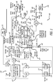
- FIG. 1 is a schematic diagram illustrating the disclosed system 100 for fiber stabilization of optical path differences (OPD) over a wide bandwidth frequency range for extended periods of time, in accordance with at least one embodiment of the present disclosure.
- a laser 105 radiates an optical beam in a first optical fiber 110.
- the first optical fiber 110 along with a second optical fiber 115 are connected to a three decibel (3 dB) beam splitter 120.
- the 3 dB beam splitter 120 splits the radiated optical beam in half, and outputs half of the optical beam (referred to as the first optical beam) on the first optical fiber 110 and the other half of the optical beam (referred to as the second optical beam) on the second optical fiber 115.
- a first circulator 125 circulates the first optical beam optionally through a bundle of fiber 130 (e.g., xxx meters of fiber) and through a fiber stretcher 135 to a translation stage 140 of an adjustable optical telescope 145.
- the first optical beam is reflected back from a first mirror 150 on the translation stage 140.
- the first circulator 125 circulates a first circulated beam, which comprises the reflected first optical beam and the adjustable optical telescope beam, to a first dichroic beam splitter 155.
- the first dichroic beam splitter 155 spits the first circulated beam into the first optical beam and the adjustable telescope beam.
- a second circulator 160 circulates the second optical beam optionally through a bundle of fiber 165 (e.g., xxx meters of fiber) and optionally through a fiber stretcher 170 to a reference optical telescope 175.
- the second optical beam is reflected back from a second mirror 180 of the reference optical telescope 175.
- the second circulator 160 circulates a second circulated beam, which comprises the reflected second optical beam and the reference optical telescope beam, to a second dichroic beam splitter 185.
- the second dichroic beam splitter 185 spits the second circulated beam into the second optical beam and the reference telescope beam.
- the adjustable telescope beam and the reference telescope beam are input into a telescope light receiving interferometer 190, which is used to produce a binocular image.
- the first optical beam is reflected off a mirror 190 and input into an OPD interferometer optical bench (e.g., a Michelson interferometer) 195.
- OPD interferometer optical bench e.g., a Michelson interferometer
- the first optical beam passes through a half wavelength ( ⁇ /2) plate with 22.5 degrees of polarization, which causes the first optical beam to have its circular polarization components (S1 and P1) in phase with each other.
- the second optical beam is input into the interferometer optical bench 195.
- the second optical beam passes through a quarter wavelength ( ⁇ /4) plate, which causes the second optical beam to have its circular polarization components (S2 and P2) 90 degrees out of phase with each other.
- the first optical beam and second optical beam then pass through a polarization beam splitter 107.
- a beam with the S1 and S2 components, where the components are in-phase (i.e. S1 + S1 I (in-phase)), are output from the interferometer optical bench 195.
- a high bandwidth (DC to 1.5 megahertz (MHz) detector 117 detects the in-phase beam (i.e. the beam with the S1 and S2 components), and produces an amplified in-phase signal.
- Another high bandwidth (DC to 1.5 MHz) detector 122 detects the quadrature beam (i.e. the beam with the P1 and P2 components), and produces an amplified quadrature signal. It should be noted that the in-phase signal and the quadrature signal together form a sinusoidal signal.
- the filtered in-phase signal and the filtered quadrature signal are input into a field programmable gate array (FPGA) digital signal processor (DSP) chassis 142 for processing.
- FPGA field programmable gate array
- DSP digital signal processor
- the analog filtered in-phase signal is input into an analog-to-digital converter (ADC) 152 to produce a digital in-phase signal.
- ADC analog-to-digital converter
- the analog filtered quadrature signal is input into an ADC 147 to produce a digital quadrature signal.
- the digital in-phase signal and the digital quadrature signal are input into a DSP 157 (or alternatively into an analog control loop of greater than 1.0 kHz with a sampling rate of greater than 20 kHz) for processing.
- the DSP 157 outputs a digital woofer command signal and a digital tweeter command signal.
- the digital woofer command signal is input into a digital-to-analog converter (DAC) 162 to produce an analog woofer command signal (DC to 5 Hz).
- the tweeter command signal is input into a DAC 167 to produce an analog tweeter command signal (5Hz to 10 kHz).
- the analog woofer command signal is input into a stage controller 172.
- the stage controller 172 sends a signal (e.g., a voltage) to control (i.e. to slide back and/or forth) the translation stage 140 according to the analog woofer signal in order to correct for OPD.
- the filtered analog tweeter signal is input into a fiber stretcher power supply 197.
- the fiber stretcher power supply 197 sends a signal (e.g., a voltage) to control the fiber stretcher 135 in order to correct for OPD.
- FIG. 2 is a schematic diagram 200 depicting further details of the disclosed system 100 of FIG. 1 , in accordance with at least one embodiment of the present disclosure.
- this figure only shows one of the beams/signals (i.e. the in-phase beam/signal or the quadrature beam/signal) being passed through the detector 117, 122 and the filter 137, 132.
- a beam i.e. either the in-phase beam or the quadrature beam
- the detector 117, 122 detects the beam, and produces an amplified signal.
- the amplified signal is input into a filter buffer card 127.
- the filter buffer card 127 filters the amplified signal to produce a filtered amplified signal.
- the analog filtered amplified signal is then input into an ADC 147, 152 to produce a digital signal.
- a digital sinusoidal signal is scaled by a scaler 205, shifted by half a wave 210, and sent through a notch filter 215.
- the resultant signal depending upon the position of a number of switches 220, is either sent through a woofer path or a tweeter path.
- a woofer/tweeter controller 225 controls the position of the switches 220. It should be noted that in FIG. 2 , the switches 220 are depicted in positions that would cause the signal to proceed to the woofer path. For the signal to proceed to both the tweeter path and the woofer path, the switches 220 will be positioned in the opposite positions than is shown in FIG. 2 .
- a wideband error signal that is sent to both the woofer and tweeter controllers.
- the woofer controller is closed first and allowed to settle down, as currently depicted by the switches 220.
- the design of the woofer loop will respond from DC to 5 Hz. Once the woofer error is approximately zero, the switches are reversed so that both the woofer and tweeter are now engaged.
- the integrated signal is then fed through a control loop 230.
- the control loop 230 produces a digital tweeter command signal.
- the digital tweeter command signal is input into a DAC 167 to produce an analog tweeter command signal.
- the analog tweeter command signal is input into a piezo amplifier, where it is amplified and filtered.
- the amplified analog tweeter command signal is then input into a fiber stretcher power supply 197, which includes a control feedback loop.
- the fiber stretcher power supply 197 sends a signal (e.g., a voltage) to control the fiber stretcher 135 in order to correct for OPD.
- the digital signal is input into a DAC 162 to produce an analog signal.
- the analog signal is then input into a stage controller 172. Inside the stage controller 172, the analog signal is input into an ADC 240 to produce a digital signal.
- the resultant signal is sent through a control feedback loop 250 to produce a control signal.
- the stage controller 172 sends the control signal (e.g., a voltage) to control (i.e. to slide back and/or forth) the translation stage 140 according to the analog woofer signal in order to correct for OPD.
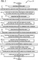
- FIG. 3 is a flow chart showing the disclosed method 300 for fiber stabilization of OPD over a wide bandwidth frequency range for extended periods of time, in accordance with at least one embodiment of the present disclosure.
- a laser radiates an optical beam 310.
- a beam splitter splits the optical beam into a first optical beam and a second optical beam 315.
- a first circulator circulates the first optical beam through a fiber stretcher to a translation stage of an adjustable optical telescope 320. Then, a first mirror on the translation stage reflects the first optical beam 325. The first circulator then circulates a first circulated beam, which comprises the first optical beam and an adjustable optical telescope beam, to a first dichroic beam splitter 330. The first dichroic beam splitter splits the first circulated beam into the first optical beam and the adjustable optical telescope beam 335.
- a second circulator circulates the second optical beam to a reference optical telescope 340. Then, a second mirror reflects the second optical beam 345. The second circulator then circulates a second circulated beam, which comprises the second optical beam and a reference optical telescope beam, to a second dichroic beam splitter 350. The second dichroic beam splitter splits the second circulated beam into the second optical beam and the reference optical telescope beam 355.
- the first optical beam and the second optical beam are input into an interferometer 360.
- the interferometer outputs an in-phase signal and a quadrature signal, which together form a sinusoidal signal 365.
- at least one processor filters the sinusoidal signal to form a high frequency signal and a low frequency signal 370.
- a stage controller controls the translation stage by using the low frequency signal 375.
- a fiber stretcher controller controls the fiber stretcher by using the high frequency signal 380. Then, the method 300 ends 385.
- FIG. 4 is a schematic diagram illustrating the telescope configuration 400 for the disclosed system 100 of FIG. 1 , in accordance with at least one embodiment of the present disclosure. Specifically, this figure shows the basic telescope geometry, where the OPD between the separated telescopes 410, 420 are controlled to maintain optical phase coherence between the two telescopes 410, 420.
- Telescope 410 is a reference optical telescope and telescope 420 is an adjustable optical telescope.
- the OPD are detected with an interferometer on the OPD bench 430, and a controller determines that needed corrections.
- the lower frequency OPD are corrected with a moveable optical bench 440.
- the higher frequency OPD are corrected by using a fiber stretcher 450 that stretches the optical fiber cable 460.
Landscapes
- Physics & Mathematics (AREA)
- General Physics & Mathematics (AREA)
- Optics & Photonics (AREA)
- Engineering & Computer Science (AREA)
- Automation & Control Theory (AREA)
- Instruments For Measurement Of Length By Optical Means (AREA)
- Telescopes (AREA)
- Mechanical Light Control Or Optical Switches (AREA)
- Microscoopes, Condenser (AREA)
- Investigating Or Analysing Materials By Optical Means (AREA)
- Optical Modulation, Optical Deflection, Nonlinear Optics, Optical Demodulation, Optical Logic Elements (AREA)
Applications Claiming Priority (1)
| Application Number | Priority Date | Filing Date | Title |
|---|---|---|---|
| US13/745,608 US9041992B2 (en) | 2013-01-18 | 2013-01-18 | Fiber stabilization of optical path differences (OPD) over a wide bandwidth frequency range for extended periods of time |
Publications (2)
| Publication Number | Publication Date |
|---|---|
| EP2757396A1 EP2757396A1 (en) | 2014-07-23 |
| EP2757396B1 true EP2757396B1 (en) | 2017-03-22 |
Family
ID=49955194
Family Applications (1)
| Application Number | Title | Priority Date | Filing Date |
|---|---|---|---|
| EP14150572.7A Active EP2757396B1 (en) | 2013-01-18 | 2014-01-09 | Fiber stabilization of optical path differences (OPD) over a wide bandwidth frequency range for extended periods of time |
Country Status (5)
| Country | Link |
|---|---|
| US (1) | US9041992B2 (enExample) |
| EP (1) | EP2757396B1 (enExample) |
| JP (1) | JP6272042B2 (enExample) |
| CN (1) | CN103944055B (enExample) |
| RU (1) | RU2642124C2 (enExample) |
Families Citing this family (3)
| Publication number | Priority date | Publication date | Assignee | Title |
|---|---|---|---|---|
| CN105446120A (zh) * | 2015-11-25 | 2016-03-30 | 天津大学 | 基于飞秒激光的光纤链路时频分布装置及其稳定方法 |
| CN107947859A (zh) * | 2017-12-12 | 2018-04-20 | 北京无线电计量测试研究所 | 一种光纤传输时延补偿装置和系统 |
| CN108828764A (zh) * | 2018-03-30 | 2018-11-16 | 深圳市华讯方舟太赫兹科技有限公司 | 一种光纤拉伸装置及光纤延迟扫描系统 |
Family Cites Families (13)
| Publication number | Priority date | Publication date | Assignee | Title |
|---|---|---|---|---|
| US4505588A (en) * | 1983-02-09 | 1985-03-19 | Ludman Jacques E | Fiber stellar interferometer |
| FR2671868B1 (fr) * | 1991-01-22 | 1993-04-30 | Aerospatiale | Dispositif interferometrique notamment stellaire, comportant une ligne a retard. |
| JPH0560781A (ja) * | 1991-09-05 | 1993-03-12 | Matsushita Electric Ind Co Ltd | 加速度測定装置 |
| JP2657018B2 (ja) * | 1991-12-24 | 1997-09-24 | 日本電信電話株式会社 | 光コネクタ反射減衰量測定装置 |
| FR2696545B1 (fr) * | 1992-10-06 | 1994-12-30 | Suisse Electronique Microtech | Interféromètre comprenant un ensemble intégré et une unité réfléchissante séparés l'un de l'autre par une région de mesure. |
| US5515199A (en) * | 1995-01-31 | 1996-05-07 | Photonic Applications, Inc. | Optical system employing near-incoherent processing for distortion correction |
| US6141099A (en) * | 1998-11-17 | 2000-10-31 | Trw Inc. | Compact, variable length interferometer delay stage |
| US6823110B2 (en) * | 2000-06-14 | 2004-11-23 | 3M Innovative Properties Company | Method to stabilize and adjust the optical path length of waveguide devices |
| JP3629515B2 (ja) * | 2000-09-11 | 2005-03-16 | 独立行政法人情報通信研究機構 | モード同期レーザ装置 |
| US7154608B1 (en) * | 2003-10-29 | 2006-12-26 | The Board Of Trustees Of Southern Illnois University | Phase-preserving amplifier for a stellar interferometer |
| GB2411066B (en) * | 2004-02-14 | 2009-04-29 | Oti Ophthalmic Technologies | Compact high resolution imaging apparatus |
| US7576868B2 (en) * | 2007-06-08 | 2009-08-18 | Zygo Corporation | Cyclic error compensation in interferometry systems |
| JP5509001B2 (ja) * | 2010-09-08 | 2014-06-04 | 日本電信電話株式会社 | 二重化光線路の光路長差検出調整装置 |
-
2013
- 2013-01-18 US US13/745,608 patent/US9041992B2/en active Active
-
2014
- 2014-01-09 EP EP14150572.7A patent/EP2757396B1/en active Active
- 2014-01-13 RU RU2014100684A patent/RU2642124C2/ru active
- 2014-01-15 JP JP2014005234A patent/JP6272042B2/ja active Active
- 2014-01-20 CN CN201410024202.XA patent/CN103944055B/zh active Active
Non-Patent Citations (1)
| Title |
|---|
| None * |
Also Published As
| Publication number | Publication date |
|---|---|
| CN103944055B (zh) | 2018-11-13 |
| US20140204439A1 (en) | 2014-07-24 |
| JP6272042B2 (ja) | 2018-01-31 |
| CN103944055A (zh) | 2014-07-23 |
| US9041992B2 (en) | 2015-05-26 |
| RU2642124C2 (ru) | 2018-01-24 |
| EP2757396A1 (en) | 2014-07-23 |
| JP2014194526A (ja) | 2014-10-09 |
| RU2014100684A (ru) | 2015-07-20 |
Similar Documents
| Publication | Publication Date | Title |
|---|---|---|
| Morzinski et al. | MagAO: Status and on-sky performance of the Magellan adaptive optics system | |
| CN111697422B (zh) | 一种相位调制型拉曼光功率控制方法及其系统 | |
| US9735537B1 (en) | Hybrid spectral and coherent beam combiner utilizing 1D fiber arrays | |
| EP2923420B1 (en) | Nested feedback loop coherent beam combining laser system | |
| EP2757396B1 (en) | Fiber stabilization of optical path differences (OPD) over a wide bandwidth frequency range for extended periods of time | |
| US11880068B2 (en) | Space optical coupling apparatus | |
| WO2013176927A2 (en) | Coherent laser array control system and method | |
| US20210341878A1 (en) | Optical scanning holography system | |
| Colavita et al. | Keck Interferometer status and plans | |
| US12000698B2 (en) | Polarization-separated, phase-shifted interferometer | |
| US6317257B1 (en) | Technique for polarization locking optical outputs | |
| KR102185432B1 (ko) | 기하 위상 인라인 스캐닝 홀로그래피 시스템 | |
| Gatto et al. | Fabry-Pérot-Michelson interferometer using higher-order Laguerre-Gauss modes | |
| CN116387954B (zh) | 一种基于光学反馈和pdh结合的频率锁定方法 | |
| JPH01276786A (ja) | 半導体レーザの自動周波数制御方法及び装置 | |
| CN107771270B (zh) | 用于使激光经由大气进行指向的光学系统与方法 | |
| KR102423055B1 (ko) | 투과체에 대한 기하 위상 인라인 스캐닝 홀로그래피 시스템 | |
| JP2014194526A5 (enExample) | ||
| Colavita et al. | Keck Interferometer nuller update | |
| WO2015046070A1 (ja) | 光学測定装置および光学測定方法 | |
| JPS59163525A (ja) | 連続駆動型マイケルソン干渉計の可動鏡駆動装置 | |
| Liu et al. | Coherent combining of multiple beams with multi-dithering technique: 100 kHz closed-loop compensation demonstration | |
| Underwood et al. | Adaptation of Dunn Solar Telescope for Jovian Doppler spectro imaging | |
| Goullioud et al. | Dim star fringe stabilization demonstration using pathlength feed-forward on the SIM Testbed 3 (STB3) | |
| Neubert et al. | Experimental implementation of an optical multiple-aperture antenna for space communications |
Legal Events
| Date | Code | Title | Description |
|---|---|---|---|
| PUAI | Public reference made under article 153(3) epc to a published international application that has entered the european phase |
Free format text: ORIGINAL CODE: 0009012 |
|
| 17P | Request for examination filed |
Effective date: 20140109 |
|
| AK | Designated contracting states |
Kind code of ref document: A1 Designated state(s): AL AT BE BG CH CY CZ DE DK EE ES FI FR GB GR HR HU IE IS IT LI LT LU LV MC MK MT NL NO PL PT RO RS SE SI SK SM TR |
|
| AX | Request for extension of the european patent |
Extension state: BA ME |
|
| GRAP | Despatch of communication of intention to grant a patent |
Free format text: ORIGINAL CODE: EPIDOSNIGR1 |
|
| INTG | Intention to grant announced |
Effective date: 20160408 |
|
| GRAJ | Information related to disapproval of communication of intention to grant by the applicant or resumption of examination proceedings by the epo deleted |
Free format text: ORIGINAL CODE: EPIDOSDIGR1 |
|
| INTC | Intention to grant announced (deleted) | ||
| GRAP | Despatch of communication of intention to grant a patent |
Free format text: ORIGINAL CODE: EPIDOSNIGR1 |
|
| INTG | Intention to grant announced |
Effective date: 20161006 |
|
| GRAJ | Information related to disapproval of communication of intention to grant by the applicant or resumption of examination proceedings by the epo deleted |
Free format text: ORIGINAL CODE: EPIDOSDIGR1 |
|
| GRAR | Information related to intention to grant a patent recorded |
Free format text: ORIGINAL CODE: EPIDOSNIGR71 |
|
| GRAS | Grant fee paid |
Free format text: ORIGINAL CODE: EPIDOSNIGR3 |
|
| GRAA | (expected) grant |
Free format text: ORIGINAL CODE: 0009210 |
|
| INTC | Intention to grant announced (deleted) | ||
| AK | Designated contracting states |
Kind code of ref document: B1 Designated state(s): AL AT BE BG CH CY CZ DE DK EE ES FI FR GB GR HR HU IE IS IT LI LT LU LV MC MK MT NL NO PL PT RO RS SE SI SK SM TR |
|
| INTG | Intention to grant announced |
Effective date: 20170214 |
|
| REG | Reference to a national code |
Ref country code: GB Ref legal event code: FG4D |
|
| REG | Reference to a national code |
Ref country code: CH Ref legal event code: EP |
|
| REG | Reference to a national code |
Ref country code: AT Ref legal event code: REF Ref document number: 878346 Country of ref document: AT Kind code of ref document: T Effective date: 20170415 |
|
| REG | Reference to a national code |
Ref country code: IE Ref legal event code: FG4D |
|
| REG | Reference to a national code |
Ref country code: DE Ref legal event code: R096 Ref document number: 602014007714 Country of ref document: DE |
|
| REG | Reference to a national code |
Ref country code: NL Ref legal event code: MP Effective date: 20170322 |
|
| PG25 | Lapsed in a contracting state [announced via postgrant information from national office to epo] |
Ref country code: LT Free format text: LAPSE BECAUSE OF FAILURE TO SUBMIT A TRANSLATION OF THE DESCRIPTION OR TO PAY THE FEE WITHIN THE PRESCRIBED TIME-LIMIT Effective date: 20170322 Ref country code: NO Free format text: LAPSE BECAUSE OF FAILURE TO SUBMIT A TRANSLATION OF THE DESCRIPTION OR TO PAY THE FEE WITHIN THE PRESCRIBED TIME-LIMIT Effective date: 20170622 Ref country code: FI Free format text: LAPSE BECAUSE OF FAILURE TO SUBMIT A TRANSLATION OF THE DESCRIPTION OR TO PAY THE FEE WITHIN THE PRESCRIBED TIME-LIMIT Effective date: 20170322 Ref country code: GR Free format text: LAPSE BECAUSE OF FAILURE TO SUBMIT A TRANSLATION OF THE DESCRIPTION OR TO PAY THE FEE WITHIN THE PRESCRIBED TIME-LIMIT Effective date: 20170623 Ref country code: HR Free format text: LAPSE BECAUSE OF FAILURE TO SUBMIT A TRANSLATION OF THE DESCRIPTION OR TO PAY THE FEE WITHIN THE PRESCRIBED TIME-LIMIT Effective date: 20170322 |
|
| REG | Reference to a national code |
Ref country code: LT Ref legal event code: MG4D |
|
| REG | Reference to a national code |
Ref country code: AT Ref legal event code: MK05 Ref document number: 878346 Country of ref document: AT Kind code of ref document: T Effective date: 20170322 |
|
| PG25 | Lapsed in a contracting state [announced via postgrant information from national office to epo] |
Ref country code: LV Free format text: LAPSE BECAUSE OF FAILURE TO SUBMIT A TRANSLATION OF THE DESCRIPTION OR TO PAY THE FEE WITHIN THE PRESCRIBED TIME-LIMIT Effective date: 20170322 Ref country code: RS Free format text: LAPSE BECAUSE OF FAILURE TO SUBMIT A TRANSLATION OF THE DESCRIPTION OR TO PAY THE FEE WITHIN THE PRESCRIBED TIME-LIMIT Effective date: 20170322 Ref country code: BG Free format text: LAPSE BECAUSE OF FAILURE TO SUBMIT A TRANSLATION OF THE DESCRIPTION OR TO PAY THE FEE WITHIN THE PRESCRIBED TIME-LIMIT Effective date: 20170622 Ref country code: SE Free format text: LAPSE BECAUSE OF FAILURE TO SUBMIT A TRANSLATION OF THE DESCRIPTION OR TO PAY THE FEE WITHIN THE PRESCRIBED TIME-LIMIT Effective date: 20170322 |
|
| PG25 | Lapsed in a contracting state [announced via postgrant information from national office to epo] |
Ref country code: NL Free format text: LAPSE BECAUSE OF FAILURE TO SUBMIT A TRANSLATION OF THE DESCRIPTION OR TO PAY THE FEE WITHIN THE PRESCRIBED TIME-LIMIT Effective date: 20170322 |
|
| PG25 | Lapsed in a contracting state [announced via postgrant information from national office to epo] |
Ref country code: EE Free format text: LAPSE BECAUSE OF FAILURE TO SUBMIT A TRANSLATION OF THE DESCRIPTION OR TO PAY THE FEE WITHIN THE PRESCRIBED TIME-LIMIT Effective date: 20170322 Ref country code: AT Free format text: LAPSE BECAUSE OF FAILURE TO SUBMIT A TRANSLATION OF THE DESCRIPTION OR TO PAY THE FEE WITHIN THE PRESCRIBED TIME-LIMIT Effective date: 20170322 Ref country code: CZ Free format text: LAPSE BECAUSE OF FAILURE TO SUBMIT A TRANSLATION OF THE DESCRIPTION OR TO PAY THE FEE WITHIN THE PRESCRIBED TIME-LIMIT Effective date: 20170322 Ref country code: ES Free format text: LAPSE BECAUSE OF FAILURE TO SUBMIT A TRANSLATION OF THE DESCRIPTION OR TO PAY THE FEE WITHIN THE PRESCRIBED TIME-LIMIT Effective date: 20170322 Ref country code: SK Free format text: LAPSE BECAUSE OF FAILURE TO SUBMIT A TRANSLATION OF THE DESCRIPTION OR TO PAY THE FEE WITHIN THE PRESCRIBED TIME-LIMIT Effective date: 20170322 Ref country code: RO Free format text: LAPSE BECAUSE OF FAILURE TO SUBMIT A TRANSLATION OF THE DESCRIPTION OR TO PAY THE FEE WITHIN THE PRESCRIBED TIME-LIMIT Effective date: 20170322 |
|
| PG25 | Lapsed in a contracting state [announced via postgrant information from national office to epo] |
Ref country code: IS Free format text: LAPSE BECAUSE OF FAILURE TO SUBMIT A TRANSLATION OF THE DESCRIPTION OR TO PAY THE FEE WITHIN THE PRESCRIBED TIME-LIMIT Effective date: 20170722 Ref country code: PL Free format text: LAPSE BECAUSE OF FAILURE TO SUBMIT A TRANSLATION OF THE DESCRIPTION OR TO PAY THE FEE WITHIN THE PRESCRIBED TIME-LIMIT Effective date: 20170322 Ref country code: SM Free format text: LAPSE BECAUSE OF FAILURE TO SUBMIT A TRANSLATION OF THE DESCRIPTION OR TO PAY THE FEE WITHIN THE PRESCRIBED TIME-LIMIT Effective date: 20170322 Ref country code: PT Free format text: LAPSE BECAUSE OF FAILURE TO SUBMIT A TRANSLATION OF THE DESCRIPTION OR TO PAY THE FEE WITHIN THE PRESCRIBED TIME-LIMIT Effective date: 20170724 |
|
| REG | Reference to a national code |
Ref country code: DE Ref legal event code: R097 Ref document number: 602014007714 Country of ref document: DE |
|
| REG | Reference to a national code |
Ref country code: FR Ref legal event code: PLFP Year of fee payment: 5 |
|
| PLBE | No opposition filed within time limit |
Free format text: ORIGINAL CODE: 0009261 |
|
| STAA | Information on the status of an ep patent application or granted ep patent |
Free format text: STATUS: NO OPPOSITION FILED WITHIN TIME LIMIT |
|
| PG25 | Lapsed in a contracting state [announced via postgrant information from national office to epo] |
Ref country code: DK Free format text: LAPSE BECAUSE OF FAILURE TO SUBMIT A TRANSLATION OF THE DESCRIPTION OR TO PAY THE FEE WITHIN THE PRESCRIBED TIME-LIMIT Effective date: 20170322 |
|
| 26N | No opposition filed |
Effective date: 20180102 |
|
| PG25 | Lapsed in a contracting state [announced via postgrant information from national office to epo] |
Ref country code: IT Free format text: LAPSE BECAUSE OF FAILURE TO SUBMIT A TRANSLATION OF THE DESCRIPTION OR TO PAY THE FEE WITHIN THE PRESCRIBED TIME-LIMIT Effective date: 20170322 Ref country code: SI Free format text: LAPSE BECAUSE OF FAILURE TO SUBMIT A TRANSLATION OF THE DESCRIPTION OR TO PAY THE FEE WITHIN THE PRESCRIBED TIME-LIMIT Effective date: 20170322 |
|
| REG | Reference to a national code |
Ref country code: CH Ref legal event code: PL |
|
| PG25 | Lapsed in a contracting state [announced via postgrant information from national office to epo] |
Ref country code: LU Free format text: LAPSE BECAUSE OF NON-PAYMENT OF DUE FEES Effective date: 20180109 |
|
| REG | Reference to a national code |
Ref country code: IE Ref legal event code: MM4A |
|
| REG | Reference to a national code |
Ref country code: BE Ref legal event code: MM Effective date: 20180131 |
|
| PG25 | Lapsed in a contracting state [announced via postgrant information from national office to epo] |
Ref country code: CH Free format text: LAPSE BECAUSE OF NON-PAYMENT OF DUE FEES Effective date: 20180131 Ref country code: LI Free format text: LAPSE BECAUSE OF NON-PAYMENT OF DUE FEES Effective date: 20180131 Ref country code: BE Free format text: LAPSE BECAUSE OF NON-PAYMENT OF DUE FEES Effective date: 20180131 |
|
| PG25 | Lapsed in a contracting state [announced via postgrant information from national office to epo] |
Ref country code: IE Free format text: LAPSE BECAUSE OF NON-PAYMENT OF DUE FEES Effective date: 20180109 |
|
| PG25 | Lapsed in a contracting state [announced via postgrant information from national office to epo] |
Ref country code: MC Free format text: LAPSE BECAUSE OF FAILURE TO SUBMIT A TRANSLATION OF THE DESCRIPTION OR TO PAY THE FEE WITHIN THE PRESCRIBED TIME-LIMIT Effective date: 20170322 |
|
| PG25 | Lapsed in a contracting state [announced via postgrant information from national office to epo] |
Ref country code: MT Free format text: LAPSE BECAUSE OF NON-PAYMENT OF DUE FEES Effective date: 20180109 |
|
| PG25 | Lapsed in a contracting state [announced via postgrant information from national office to epo] |
Ref country code: TR Free format text: LAPSE BECAUSE OF FAILURE TO SUBMIT A TRANSLATION OF THE DESCRIPTION OR TO PAY THE FEE WITHIN THE PRESCRIBED TIME-LIMIT Effective date: 20170322 |
|
| PG25 | Lapsed in a contracting state [announced via postgrant information from national office to epo] |
Ref country code: HU Free format text: LAPSE BECAUSE OF FAILURE TO SUBMIT A TRANSLATION OF THE DESCRIPTION OR TO PAY THE FEE WITHIN THE PRESCRIBED TIME-LIMIT; INVALID AB INITIO Effective date: 20140109 |
|
| PG25 | Lapsed in a contracting state [announced via postgrant information from national office to epo] |
Ref country code: MK Free format text: LAPSE BECAUSE OF NON-PAYMENT OF DUE FEES Effective date: 20170322 Ref country code: CY Free format text: LAPSE BECAUSE OF FAILURE TO SUBMIT A TRANSLATION OF THE DESCRIPTION OR TO PAY THE FEE WITHIN THE PRESCRIBED TIME-LIMIT Effective date: 20170322 |
|
| PG25 | Lapsed in a contracting state [announced via postgrant information from national office to epo] |
Ref country code: AL Free format text: LAPSE BECAUSE OF FAILURE TO SUBMIT A TRANSLATION OF THE DESCRIPTION OR TO PAY THE FEE WITHIN THE PRESCRIBED TIME-LIMIT Effective date: 20170322 |
|
| REG | Reference to a national code |
Ref country code: DE Ref legal event code: R082 Ref document number: 602014007714 Country of ref document: DE Representative=s name: KILBURN & STRODE LLP, NL |
|
| P01 | Opt-out of the competence of the unified patent court (upc) registered |
Effective date: 20230516 |
|
| PGFP | Annual fee paid to national office [announced via postgrant information from national office to epo] |
Ref country code: DE Payment date: 20250129 Year of fee payment: 12 |
|
| PGFP | Annual fee paid to national office [announced via postgrant information from national office to epo] |
Ref country code: FR Payment date: 20250127 Year of fee payment: 12 |
|
| PGFP | Annual fee paid to national office [announced via postgrant information from national office to epo] |
Ref country code: GB Payment date: 20250127 Year of fee payment: 12 |