EP2757366A1 - Biological information detection sensor supply device - Google Patents
Biological information detection sensor supply device Download PDFInfo
- Publication number
- EP2757366A1 EP2757366A1 EP20120831599 EP12831599A EP2757366A1 EP 2757366 A1 EP2757366 A1 EP 2757366A1 EP 20120831599 EP20120831599 EP 20120831599 EP 12831599 A EP12831599 A EP 12831599A EP 2757366 A1 EP2757366 A1 EP 2757366A1
- Authority
- EP
- European Patent Office
- Prior art keywords
- feeding
- biological information
- sensor
- information detection
- detection sensor
- Prior art date
- Legal status (The legal status is an assumption and is not a legal conclusion. Google has not performed a legal analysis and makes no representation as to the accuracy of the status listed.)
- Granted
Links
Images










Classifications
-
- A—HUMAN NECESSITIES
- A61—MEDICAL OR VETERINARY SCIENCE; HYGIENE
- A61B—DIAGNOSIS; SURGERY; IDENTIFICATION
- A61B5/00—Measuring for diagnostic purposes; Identification of persons
- A61B5/145—Measuring characteristics of blood in vivo, e.g. gas concentration or pH-value ; Measuring characteristics of body fluids or tissues, e.g. interstitial fluid or cerebral tissue
- A61B5/14532—Measuring characteristics of blood in vivo, e.g. gas concentration or pH-value ; Measuring characteristics of body fluids or tissues, e.g. interstitial fluid or cerebral tissue for measuring glucose, e.g. by tissue impedance measurement
-
- G—PHYSICS
- G01—MEASURING; TESTING
- G01N—INVESTIGATING OR ANALYSING MATERIALS BY DETERMINING THEIR CHEMICAL OR PHYSICAL PROPERTIES
- G01N33/00—Investigating or analysing materials by specific methods not covered by groups G01N1/00 - G01N31/00
- G01N33/48—Biological material, e.g. blood, urine; Haemocytometers
- G01N33/483—Physical analysis of biological material
- G01N33/487—Physical analysis of biological material of liquid biological material
- G01N33/4875—Details of handling test elements, e.g. dispensing or storage, not specific to a particular test method
- G01N33/48764—Test tape taken off a spool
-
- G—PHYSICS
- G01—MEASURING; TESTING
- G01N—INVESTIGATING OR ANALYSING MATERIALS BY DETERMINING THEIR CHEMICAL OR PHYSICAL PROPERTIES
- G01N35/00—Automatic analysis not limited to methods or materials provided for in any single one of groups G01N1/00 - G01N33/00; Handling materials therefor
- G01N35/00009—Automatic analysis not limited to methods or materials provided for in any single one of groups G01N1/00 - G01N33/00; Handling materials therefor provided with a sample supporting tape, e.g. with absorbent zones
-
- G—PHYSICS
- G01—MEASURING; TESTING
- G01N—INVESTIGATING OR ANALYSING MATERIALS BY DETERMINING THEIR CHEMICAL OR PHYSICAL PROPERTIES
- G01N35/00—Automatic analysis not limited to methods or materials provided for in any single one of groups G01N1/00 - G01N33/00; Handling materials therefor
- G01N35/00009—Automatic analysis not limited to methods or materials provided for in any single one of groups G01N1/00 - G01N33/00; Handling materials therefor provided with a sample supporting tape, e.g. with absorbent zones
- G01N2035/00019—Automatic analysis not limited to methods or materials provided for in any single one of groups G01N1/00 - G01N33/00; Handling materials therefor provided with a sample supporting tape, e.g. with absorbent zones cassette structures
Definitions
- the present invention relates to a biological information detection sensor feeding apparatus. More specifically, the present invention relates to a biological information detection sensor feeding apparatus that feeds a biological information detection sensor such as a blood glucose sensor, for example.
- a conventional biological information detection sensor feeding apparatus includes, for example, a body case having a feeding opening for a test element (an example of a biological information detection sensor); a storage section that stores a strip-shaped sensor feeding film in the body case; and a feeding section that feeds a predetermined length of the sensor feeding film from the storage section to the feeding opening.
- the feeding section is configured to feed a predetermined length of the sensor feeding film to the feeding opening, and immediately before the feeding opening, peel a covering film from a surface of a holding film constituting the sensor feeding film (see PTL 1).
- one biological information detection sensor (an example of a test element) is fed to the feeding opening.
- the user may unwittingly contaminate the biological information detection sensor by dropping.
- an object of the present invention is to provide a biological information detection sensor feeding apparatus that is easy to use.
- a biological information detection sensor feeding apparatus includes: a body case having a feeding stage; a storage section that stores a strip-shaped sensor feeding film in the body case, the sensor feeding film including a biological information detection sensor, and a holding film and a covering film that sandwich the biological information detection sensor; and a feeding section that feeds the biological information detection sensor from the storage section to the feeding stage.
- the feeding section is configured to feed the holding film of the sensor feeding film and the biological information detection sensor to the feeding stage, and peel the covering film from the sensor feeding film before feeding the biological information detection sensor to the feeding stage, and is configured to wind the holding film fed to the feeding stage.
- the feeding stage inclines downward along a feeding direction of the sensor feeding film.
- a biological information detection sensor feeding apparatus includes: a body case having a feeding opening configured such that a biological information measurer can be attached thereto; a storage section that stores a strip-shaped sensor feeding film in the body case, the sensor feeding film including a biological information detection sensor, and a holding film and a covering film that sandwich the biological information detection sensor; and a feeding section that feeds the biological information detection sensor from the storage section to the feeding opening.
- the feeding section is configured to feed the biological information detection sensor to the feeding opening, and separate the holding film and the covering film from the sensor feeding film before feeding the biological information detection sensor to the feeding opening.
- the feeding section is configured to load the biological information detection sensor fed to the feeding opening, into the biological information measurer attached to the feeding opening.
- a biological information detection sensor feeding apparatus includes: a measuring section that measures biological information; a body case having a loading opening; a storage section that stores a strip-shaped sensor feeding film in the body case, the sensor feeding film including a biological information detection sensor, and a holding film and a covering film that sandwich the biological information detection sensor; and a feeding section that feeds the biological information detection sensor from the storage section to the loading opening.
- the feeding section is configured to feed the biological information detection sensor to the loading opening, and separate the holding film and the covering film from the sensor feeding film before feeding the biological information detection sensor to the loading opening.
- the loading opening includes a connector connected with the measuring section and the biological information detection sensor includes a connecting electrode, and the feeding section is configured to feed the biological information detection sensor to the loading opening such that the connecting electrode of the biological information detection sensor is electrically connected with the connecter of the loading opening.
- a biological information detection sensor feeding apparatus it is possible to easily load a biological information detection sensor into a biological information measurer and to simplify the measurement of biological information.
- FIG. 1 shows biological information detection sensor feeding apparatus 1.
- a user of biological information detection sensor feeding apparatus 1 is a nurse in a hospital, for example.
- Biological information detection sensor feeding apparatus 1 has body case 2 molded in an approximately cuboidal shape, and feeding stage 4 provided on the upper surface of the front-end side of body case 2.
- a biological information detection sensor (for example, blood glucose sensor 3) is fed to feeding stage 4.
- Operating lever 5 is provided at the rear side of body case 2. By an operation of operating lever 5, blood glucose sensors 3 can be fed to feeding stage 4 one by one.
- blood glucose sensor 3 is stored in strip-shaped sensor feeding film 6.
- Sensor feeding film 6 includes strip-shaped holding film 7 and strip-shaped covering film 8 that covers a surface of holding film 7.
- Blood glucose sensor 3 is stored between strip-shaped holding film 7 and strip-shaped covering film 8. That is, on the surface of holding film 7, multiple (in the embodiment, 200) blood glucose sensors 3 are arranged at a predetermined interval along the longitudinal direction of holding film 7.
- the longitudinal direction of stored blood glucose sensors 3 is orthogonal to the longitudinal direction of holding film 7, but is not particularly limited.
- discrimination information is indicated in the vicinity of each blood glucose sensor 3.
- the discrimination information is, for example, the holding number of each blood glucose sensor 3.
- the holding numbers, which are given in the arrangement order of blood glucose sensors 3, may be in the descending order (for example, from 200 to 1), or may be in the ascending order (for example, from 1 to 200).
- feed guide holes 9 for feeding a predetermined length of sensor feeding film 6 to feeding stage 4 in FIG. 1 .
- FIG. 3A is a cross-sectional diagram of biological information detection sensor feeding apparatus 1 when body case 2 is viewed in the lateral direction
- FIG. 3B is an enlarged cross-sectional diagram of biological information detection sensor feeding apparatus 1 when the principal part around feeding stage 4 of body case 2 is viewed in the lateral direction
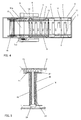
- FIG. 4 is a perspective diagram of biological information detection sensor feeding apparatus 1 when body case 2 is viewed from the upper surface side.
- a roll of sensor feeding film 6 is stored in storage section 10 provided in the interior of body case 2.
- Storage section 10 only has to be positioned near the center of the interior of body case 2.
- sensor feeding film 6 is loosely wound in a roll so that blood glucose sensor 3 held in sensor feeding film 6 is not damaged.
- the roll of sensor feeding film 6 is disposed such that the unwinding direction of the roll is oriented to feeding stage 4 in the vicinity of the front-end of body case 2. As shown in FIG. 3A , sensor feeding film 6 is fed to feeding stage 4. In sensor feeding film 6 to be fed, holding film 7, blood glucose sensor 3 and covering film 8, from the bottom in the drawing, are sequentially laminated.
- Feeding stage 4 is connected with guiding section 4a.
- Guiding section 4a is a board within body case 2, and is positioned between storage section 10 and feeding stage 4.
- Guiding section 4a is a board for guiding sensor feeding film 6 to feeding stage 4.
- Cylindrical pressing pulley 11 is disposed above guiding section 4a in the vicinity of storage section 10.
- the axial length of pressing pulley 11 is greater than the short-directional width of sensor feeding film 6.
- pressing pulley 11. can press the whole of the short-directional width of sensor feeding film 6 onto guiding section 4a.
- cylindrical separating pulley 12 In the interior of body case 2, cylindrical separating pulley 12 is provided above guiding section 4a in the vicinity of feeding stage 4. Separating pulley 12 separates covering film 8 from sensor feeding film 6. The separated covering film is returned upward and subsequently rearward, and through cylindrical guiding pulleys 13, 14 and cylindrical driving reel 15, is wound by winding reel 16. As understood from FIG. 4 , the axis-directional lengths of separating pulley 12, guiding pulleys 13, 14 and driving reel 15 are longer than the short-directional width of sensor feeding film 6.
- blood glucose sensor 3 uncovered on the surface of holding film 7 is fed to feeding stage 4.
- the board area of feeding stage 4 is greater than the area of blood glucose sensor 3.
- Blood glucose sensor 3 held on feeding stage 4 is obtained by a user.
- cylindrical returning pulley 17 is provided downstream of feeding stage 4 (downstream side in the feeding direction of sensor feeding film 6). Holding film 7 of sensor feeding film 6 is returned downward and subsequently rearward by returning pulley 17, and through cylindrical guiding pulleys 18, 19 and cylindrical driving reel 20, is wound by winding reel 21.
- the axial lengths of returning pulley 17, guiding pulleys 18, 19 and driving reel 20 are longer than the short-directional width of sensor feeding film 6.
- Driving projections 15a, 20a are provided at both ends respectively of driving reels 15, 20. Driving projections 15a, 20a engage with feed guide holes 9 provided at both ends of sensor feeding film 6. Driving reels 15, 20 are coupled with operating lever 5.
- a winding mechanism for covering film 8 of sensor feeding film 6 is constituted by operating lever 5, winding reel 16, driving reel 15, guiding pulleys 14, 13 and separating pulley 12.
- a winding mechanism for holding film 7 of sensor feeding film 6 is constituted by operating lever 5, winding reel 21, driving reel 20, guiding pulleys 19, 18 and returning pulley 17.
- the winding mechanism for covering film 8 and the winding mechanism for holding film 7 are constituent members of the feeding section that feeds a biological information detection sensor.
- Winding reel 16 that constitutes the winding mechanism for covering film 8 is provided so as to be connected with driving reel 15, and has a slipping clutch mechanism.
- Winding reel 21 that constitutes the winding mechanism for holding film 7 is provided so as to be connected with driving reel 20, and has a slipping clutch mechanism.
- Winding reel 16 shown in FIG. 5 has reel spindle 22, Gear 23 is provided at one end of reel spindle 22, and spring retainer 24 is provided at the other end. Around reel spindle 22, coil spring 25 is attached in a compression state.
- reeling part 26 is attached through coil spring 25.
- coil spring 25 the gear 23 side end of reeling part 26 is pressed onto gear 23 through slipping member 27 composed of felt.
- Winding reel 16 is connected with driving reel 15 by gear 23 (see FIG. 3A ), and winding reel 16 is configured to rotate 1.2 cycles when driving reel 15 rotates 1 cycle. Thereby, the rotation amount of winding reel 16 is more than the rotation amount of driving reel 15. However, since the slipping clutch mechanism of winding reel 16 allows winding reel 16 to appropriately run idle, winding reel 16 can appropriately wind covering film 8 to which an appropriate tension is given.
- Winding reel 21 to wind holding film 7 can be configured in the same manner as winding reel 16. Accordingly, winding reel 21 can appropriately wind holding film 7 to which an appropriate tension is given.
- Operating lever 5 is connected with driving reel 20 and driving reel 15 through a ratchet mechanism.
- driving reel 20 and driving reel 15 rotate in predetermined directions.
- the rotation amounts of driving reel 20 and driving reel 15 are set so as to correspond to the operation amount of operating lever 5.
- FIG. 1 a user (for example, a nurse) holds the upper surface of the front-end side of body case 2 with the right hand, for example, and pulls up operating lever 5 rearward by a predetermined amount with the left hand. Then, corresponding to the operation of operating lever 5, driving reel 20 rotates in a predetermined direction (see FIG. 3A ). Similarly, driving reel 15 connected with driving reel 20 also rotates in a predetermined direction.
- Driving projections 15a of driving reel 15 transmit driving force to covering film 8, through feed guide holes 9 of covering film 8 that engage with driving projections 15a. Thereby, covering film 8 is unwound from storage section 10 by a predetermined amount corresponding to the operation of operating lever 5, by the winding mechanism for covering film 8 (operating lever 5, winding reel 16, driving reel 15, guiding pulleys 14, 13, and separating pulley 12).
- Driving projections 20a of driving reel 20 transmit driving force to holding film 7, through feed guide holes 9 of holding film 7 that engage with driving projections 20a. Thereby, holding film 7 is unwound from storage section 10 by a predetermined amount corresponding to the operation of operating lever 5, by the feeding section for holding film 7 (operating lever 5, winding reel 21, driving reel 20, guiding pulleys 19, 18, and returning pulley 17).
- covering film 8 and holding film 7, which constitute sensor feeding film 6, are unwound by the same predetermined amount, in other words, sensor feeding film 6 is fed to feeding stage 4.
- covering film 8 is peeled from holding film 7 by separating pulley 12 provided above guiding section 4a, and then is rolled upward, Cover film 8 is subsequently returned rearward, and through guiding pulleys 13, 14 and driving reel 15, is wound by winding reel 16.
- covering film 8 is peeled from holding film 7 by separating pulley 12, blood glucose sensor 3, which has been sandwiched by holding film 7 and covering film 8, is uncovered. Then, blood glucose sensor 3 uncovered on the surface of holding film 7 is fed to feeding stage 4.
- feeding stage 4 is configured such that the size thereof is greater than the size of blood glucose sensor 3. Thereby, blood glucose sensor 3 is stably held on feeding stage 4, and does not drop out of feeding stage 4.
- a user In order to pick up blood glucose sensor 3 fed to feeding stage 4, for example, a user (a nurse) holds blood glucose sensor 3 with the pulp of forefinger F of the right hand, slides and moves blood glucose sensor 3 along feeding stage 4 (rightward in FIG. 4 ), and then pulls it out to the exterior of feeding stage 4 (for example, the upper side or the lower side in FIG. 4 ). The user pinches with the forefinger and the thumb the upper and lower sides of blood glucose sensor 3 pulled out of feeding stage 4 in this way. Thus, blood glucose sensor 3 can be stably picked up from feeding stage 4.
- feeding stage 4 has inclining portion 4b that inclines downward along the feeding direction of sensor feeding film 6.
- the returning pulley 17 side end of feeding stage 4 is disposed below the upper end of returning pulley 17. That is, the upper end of returning pulley 17 protrudes above the returning pulley 17 side end of feeding stage 4.
- inclining portion 4b gradually inclines downward along the feeding direction of sensor feeding film 6 (as going to returning pulley 17); the inclination angle of inclining portion 4b is not particularly limited. It is desirable that the inclination angle of inclining portion 4b be determined such that blood glucose sensor 3 can be easily taken out, in consideration of the largeness of feeding stage 4, the length of inclining portion 4b, the size of the finger, the diameter length of returning pulley 17 and the like.
- the user can more stably pick up blood glucose sensor 3 fed to feeding stage 4, compared to the case where feeding stage 4 does not have inclining portion 4b. That is, in order to pick up blood glucose sensor 3 from feeding stage 4 having inclining portion 4b, for example, the user holds the upper surface of blood glucose sensor 3 with the pulp of forefinger F of the right hand (see FIG. 3B ), and then, slides and moves it downward (rightward in FIG. 4 ) along inclining portion 4b of feeding stage 4. Since feeding stage 4 has inclining portion 4b, blood glucose sensor 3 on the upper surface of feeding stage 4 is easily slid. In addition, it is possible to allow the longitudinal side end of blood glucose sensor 3 to abut against returning pulley 17 protruding above feeding stage 4. Since the whole of the longitudinal side end of blood glucose sensor 3 is allowed to abut against returning pulley 17, blood glucose sensor 3 can stably abut against returning pulley 17.
- the user can pull out blood glucose sensor 3 to the exterior of feeding stage 4 (for example, the upper side or the lower side in FIG. 4 ) along returning pulley 17.
- feeding stage 4 for example, the upper side or the lower side in FIG. 4
- returning pulley 17 By pinching the upper and lower sides of this pulled-out blood glucose sensor 3 with the forefinger and the thumb, it is possible to pick up blood glucose sensor 3 more steadily from the feeding stage.
- feeding stage 4 has inclining portion 4b, it is possible to utilize returning pulley 17 constituting the feeding stage for drop prevention of blood glucose sensor 3, and to achieve a simplification of a configuration for drop prevention. As a result, blood glucose sensor 3 is not dropped, and it is possible to increase ease of use.
- blood glucose sensor 3 can be fed to feeding stage 4 one by one.
- the discrimination information of blood glucose sensor 3 is printed in the vicinity of blood glucose sensor 3 allowing the user to confirm (e.g., by visually) the identity of blood glucose sensor 3.
- the discrimination information is, for example, the holding number (the number information of blood glucose sensor 3) that shows the holding order of blood glucose sensor 3.
- the holding number is printed for each blood glucose sensor 3, in the descending order (for example, from 200 to 1) or in the ascending order (for example, from 1 to 200).
- the nurse thus checks the holding number by visual observation when picking up blood glucose sensor 3 from feeding stage 4, and thereby confirms the number of blood glucose sensors 3 remaining in the apparatus, thus facilitating the use of apparatus.
- the discrimination information printed in the vicinity of blood glucose sensor 3 is not limited to the above holding number; the discrimination information may be a code that shows the model, production lot number, usable period, destination and other information of blood glucose sensor 3. Thereby, it is possible to increase safety in work for the blood test.
- a rotary lever is exemplified as operating lever 5, but operating lever 5 is not limited to a rotary lever, and may be a rotating operating lever with a handle, a sliding operating lever, or an operating button for electric operation.
- FIG. 6 shows biological information detection sensor feeding apparatus 28 according to Embodiment 2.
- Biological information detection sensor feeding apparatus 28 feeds blood glucose sensor 30 (an example of a biological information detection sensor) shown in FIG. 7 , to measurer 29 that measures biological information (for example, blood glucose level).
- blood glucose sensor 30 an example of a biological information detection sensor
- measurer 29 measures biological information (for example, blood glucose level).
- cubic sensor loading section 32 provided at the end of measurer 29 is attached (inserted) to sensor feeding opening 31 ( FIG. 8 ) provided at the front-end of biological information detection sensor feeding apparatus 28
- the "loaded” means that blood glucose sensor 30 is electrically connected to an electric circuit of measurer 29.
- Biological information detection sensor feeding apparatus 28 has approximately cuboidal body case 33. As shown in FIG. 8 and FIG. 9 , at the front-end side of body case 33, there is provided feeding opening 31 to which blood glucose sensor 30 (an example of a biological information detection sensor) is fed.
- blood glucose sensor 30 an example of a biological information detection sensor
- operating lever 34 for feeding blood glucose sensor 30 to feeding opening 31 one by one.
- blood glucose sensor 30 is stored in strip-shaped sensor feeding film 35.
- Sensor feeding film 35 is constituted by strip-shaped holding film 36 and strip-shaped covering film 37 that covers a surface of holding film 36.
- Blood glucose sensor 30 is stored between strip-shaped holding film 36 and strip-shaped covering fihn 37. That is, on the surface of holding film 36, multiple (in the embodiment, 200 blood glucose sensors 30 are arranged at a predetermined interval along the longitudinal direction of holding film 36. Thus, blood glucose sensor 30 is held while being sandwiched between holding film 36 and covering film 37.
- Blood glucose sensor 30 has a thin-plate shape. Spot-application portion 38 on which blood is to be spot-applied is provided on a protruding portion provided at one end, and connecting electrodes 39 are provided from the center portion to the other side end.
- Feed guide holes 40 are provided at both ends in the direction orthogonal to the longitudinal direction of sensor feeding film 35. Through feed guide holes 40, driving force is transmitted to sensor feeding film 35, and a predetermined length of sensor feeding film 35 is fed toward feeding opening 31 of body case 33.
- FIG. 9 is a cross-sectional diagram of biological information detection sensor feeding apparatus 28 when body case 33 is viewed in the lateral direction.
- FIG. 10 is a perspective diagram of biological information detection sensor feeding apparatus 28 when body case 33 is viewed in the overhead direction. For description of the interval mechanism, FIG. 10 shows a state in which the upper surface of body case 33 is removed.
- a roll of sensor feeding film 35 is stored in storage section 41 of body case 33.
- Storage section 41 only has to be provided near the center of the interior of body case 33.
- Sensor feeding film 35 is loosely wound so that blood glucose sensor 30 stored therein is not damaged.
- the roll of sensor feeding film 35 is disposed such that the unwinding direction of sensor feeding film 35 is oriented to feeding opening 31 provided at the front-end side of body case 33.
- sensor feeding film 35 in which from the bottom in the drawing, holding film 36, blood glucose sensor 30 and covering film 37 are sequentially laminated, is fed toward feeding opening 31.
- Blood glucose sensor 30 is held on holding film 36 such that connecting electrodes 39 of blood glucose sensor 30 fed to sensor feeding opening 31 opposes sensor loading section 32.
- body case 33 of biological information detection sensor feeding apparatus 28 has cuboidal sensor feeding space 42 that allows feeding opening 31 and the interior of body case 33 to communicate with each other.
- Sensor holding section 43 is provided at the inward side (the leftward side in FIG. 9 , the side opposite to feeding opening 31) of sensor feeding space 42. Through sensor holding section 43, blood glucose sensor 30 is fed to sensor feeding space 42.
- the length from sensor holding section 43 to feeding opening 31 of sensor feeding space 42 is greater than the length of blood glucose sensor 30 (the length from the end of the spot-application portion 38 side to the end of the connecting electrode 39 side).
- the vicinity of feeding opening 31 in sensor feeding space 42 has a taper shape, and the opening area of sensor feeding space 42 becomes larger outward. Thereby, the sensor loading section 32 (see FIG. 6 ) of measurer 29 is easily inserted to sensor feeding space 42.
- cylindrical separating pulleys 44, 45 are provided at a region opposite to sensor holding section 43. Furthermore, a pair of cylindrical pressing pulleys 46, 47 is disposed at the inward side (storage section 41 side) of separating pulleys 44, 45. Pressing pulleys 46, 47 have a length that is greater than the short-directional width of sensor feeding film 35, and press the whole of the short-directional width of sensor feeding film 35. Pressing pulleys 46, 47 correct peculiar windings remaining in unwound sensor feeding film 35, and send it to the gap between separating pulleys 44, 45.
- Separating pulleys 44, 45 separate sensor feeding film 35 into covering film 37 and holding film 36.
- Separating pulley 44 returns covering film 37 of sensor feeding film 35 upward and subsequently rearward.
- Covering film 37 is wound by cylindrical winding reel 51, through cylindrical guiding pulleys 48, 49 and cylindrical driving reel 50.
- the axial lengths of separating pulley 44, guiding pulleys 48, 49 and driving reel 50 are greater than the short-directional width of sensor feeding film 35.
- separating pulley 45 returns holding film 36 of sensor feeding film 35 downward and subsequently rearward.
- Holding film 36 is wound by cylindrical winding reel 55, through cylindrical guiding pulleys 52, 53 and cylindrical driving reel 54.
- the axial lengths of separating pulley 45, guiding pulleys 52, 53 and driving reel 54 are greater than the short-directional width of sensor feeding film 35.
- Driving projections 50a, 54a are provided at both end sides of driving reels 50, 54. Driving projections 50a, 54a engage with feed guide holes 40 provided at both ends of sensor feeding film 35. Driving reels 50, 54 are coupled with operating lever 34.
- a winding mechanism for covering film 37 of sensor feeding film 35 is constituted by operating lever 34, winding reel 51, driving reel 50, guiding pulleys 49, 48 and separating pulley 44.
- a winding mechanism for holding film 36 of sensor feeding film 35 is constituted by operating lever 34, winding reel 55, driving reel 54, guiding pulleys 53, 52 and separating pulley 45.
- Winding reel 51 has the same slipping clutch mechanism as Embodiment 1, and is connected with driving reel 50.
- Winding reel 55 has the same slipping clutch mechanism as Embodiment 1, and is connected with driving reel 54.
- Operating lever 34 is connected with driving reel 50 and driving reel 54 through a ratchet mechanism.
- Driving reel 50 and driving reel 54 rotate in predetermined directions, only when operating lever 34 is pulled up rearward (see FIG. 6 ).
- the rotation amounts of driving reel 50 and driving reel 54 correspond to the operation of operating lever 34.
- biological information detection sensor feeding apparatus 28 having the above configuration in use will be described hereinafter.
- a user for example, holds the upper surface of the front-end side of body case 33 with the right hand, and pulls up operating lever 34 rearward by a predetermined amount with the left hand (see FIG. 6 ).
- driving reel 50 and driving reel 54 rotate in predetermined directions by the amounts corresponding to the operation of operating lever 34 (see FIG. 9 ).
- Driving projections 50a of driving reel 50 transmit driving force to covering film 37 through feed guide holes 40 of covering film 37.
- covering film 37 is pulled out from storage section 41 to feeding opening 31 side by a predetermined amount corresponding to the operation of operating lever 34, by the winding mechanism for covering film 37 (operating lever 34, winding reel 51, driving reel 50, guiding pulleys 49, 48, and separating pulley 44).
- Driving projections 54a of driving reel 54 transmit driving force to holding film 36 through feed guide holes 40 of holding film 36.
- holding film 36 is pulled out from storage section 41 to feeding opening 31 side by a predetermined amount corresponding to the operation of operating lever 34, by the winding mechanism for holding film 36 (operating lever 34, driving reel 54, guiding pulleys 53, 52, separating pulley 45, and winding reel 55).
- covering film 37 and holding film 36 are pulled out to feeding opening 31 side by the same predetermined amount.
- sensor feeding film 35 is pulled out.
- Covering film 37 and holding film 36 are separated from pulled-out sensor feeding film 35 by separating pulleys 44, 45. Then, one blood glucose sensor 30 stored in sensor feeding film 35 is fed to sensor feeding space 42.
- FIG. 11 shows a state in which one blood glucose sensor 30 has been fed to sensor feeding space 42.
- FIG 11 is an enlarged cross-sectional diagram of the vicinity of feeding opening 31.
- blood glucose sensor 30 fed to sensor feeding space 42 can be stably held by sensor holding section 43.
- sensor holding section 43 has guiding opening 56 that is opened in an oblong shape. Guiding opening 56 is formed in a taper shape, in order to easily guide blood glucose sensor 30 to feeding opening 31 side.
- the gap of the opening portion is nearly equal to, or slightly greater than the thickness of blood glucose sensor 30.
- sandwiching section 57 which sandwiches blood glucose sensor 30 that has been guided to guiding opening 56 and moved to feeding opening 31 side. That is, sensor holding section 43 is constituted by guiding opening 56 and sandwiching section 57.
- the opening area of the inward side (the leftward side in FIG. 11 , the side from guiding opening 56 to separating pulleys 44, 45) of body case 33 is greater than the opening area of the outward side (the rightward side in FIG. 11 , the side from guiding opening 56 to feeding opening 31) of body case 33.
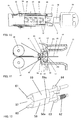
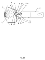
- FIG. 12 and FIG. 13 are enlarged perspective diagrams of sandwiching section 57, viewed from feeding opening 31 side.
- sandwiching section 57 has oblong sandwiching claws 58, 59 opposite to each other, which are disposed such that the opposing portion between sandwiching claws 58, 59 is parallel to the long axis of guiding opening 56 (see FIG. 11 ).
- the opposing portion between sandwiching claws 58, 59 corresponds to abutting portions 58a, 59a that abut against blood glucose sensor 30.
- abutting portions 58a, 59a are configured to sandwich the top and bottom surfaces of blood glucose sensor 30.
- Sandwiching section 57 has rotating shafts 60, 61 that rotate sandwiching claws 58, 59. As shown in FIG. 11 , abutting portions 58a, 59a are disposed closer to feeding opening 31 than rotating shafts 60, 61. Thereby, sandwiching section 57 sandwiches blood glucose sensor 30 at a position closer to feeding opening 31 than rotating shafts 60, 61.
- rotating shafts 60, 61 are equipped with rotating cams 63, 64, and rotate synchronously therewith. Thereby, abutting portions 58a, 59a of sandwiching section 57 can always sandwich blood glucose sensor 30 at the same position.
- rotating shaft 60 includes spring 62.
- spring 62, rotating cam 63 and rotating cam 64 always bias sandwiching claws 58, 59, and act to abut against abutting portions 58a, 59a.
- abutting portions 58a, 59a are disposed closer to feeding opening 31 than rotating shafts 60, 61.
- blood glucose sensor 30 which advances from rotating shafts 60, 61 side to feeding opening 31 side (from the left side to the right side in FIG. 11 ), can open sandwiching claws 58, 59. That is, sandwiching claws 58, 59 do not obstruct the advance of blood glucose sensor 30.
- sandwiching section 57 sandwiches the center portion of blood glucose sensor 30, as shown in FIG. 15 .
- blood glucose sensor 30 can be held by sandwiching.
- blood glucose sensor 30 can be held by the opening portion on feeding opening 31 side in guiding opening 56 while being sandwiched by sandwiching section 57. Thereby, it is possible to stably keep the position of blood glucose sensor 30 fed to sensor feeding space 42.
- a user attaches (inserts) sensor loading section 32 (see FIG. 10 ) of measurer 29 from feeding opening 31 to sensor feeding space 42.
- connecting electrodes 39 of blood glucose sensor 30 held in sensor feeding space 42 are mechanically and electrically connected to connector 65 in sensor loading section 32.
- sensor loading section 32 would push back blood glucose sensor 30.
- sandwiching claws 58, 59 strongly sandwiches the upper and lower surfaces of blood glucose sensor 30, and therefore blood glucose sensor 30 is not pushed back. Thereby, blood glucose sensor 30 can be appropriately connected to connector 65.
- blood glucose sensor 30 has guiding cutouts 66 provided by cutting out the end of the connecting electrode 39 side. By guiding cutouts 66, blood glucose sensor 30 is guided to connector 65 so that connecting electrodes 39 can be appropriately connected to connector 65.
- sandwiching claws 58, 59 When inserting sensor loading section 32 of measurer 29 to sensor feeding space 42, sandwiching claws 58, 59 strongly sandwiches the upper and lower surfaces of blood glucose sensor 30. Thereafter, by pulling out sensor loading section 32 of measurer 29 from sensor feeding space 42, the sandwiching between sandwiching claws 58, 59 becomes loose and blood glucose sensor 30 is released. As a result, as shown in FIG. 17 , blood glucose sensor 30 is securely transferred to measurer 29.
- connector 65 of sensor loading section 32 is configured to connect with connecting electrodes 39 of blood glucose sensor 30 while being pressed thereon, when blood glucose sensor 30 is inserted to sensor loading section 32. This stabilizes the electric connecting condition between connector 65 and connecting electrodes 39, and results in a more secure loading of blood glucose sensor 30 into blood glucose sensor 30.
- biological information detection sensor feeding apparatus 28 has the following features.
- a user himself does not need to peel sensor feeding film 35 in order to take out blood glucose sensors 30 from sensor feeding film 35 one by one.
- the embodiment makes it possible to easily load blood glucose sensor 30 into measurer 29, and therefore is easy to use.
- Embodiment 2 differs from the above-described Embodiment 1 in the orientation of blood glucose sensor 30 that is being stored in sensor feeding film 35. This is because a main object of Embodiment 1 is to securely and easily take out blood glucose sensor 3 with fingers or the like, whereas a main object of Embodiment 2 is to directly load blood glucose sensor 30 into loading section 32 of measurer 29.
- measurer 29' has displaying section 29a that displays measured values and the like, operating section 29b that is constituted by various buttons, and sensor loading section 32' into which biological information detection sensor 30 is to be loaded.
- Biological information detection sensor feeding apparatus 28' has the same configuration as the above-described biological information detection sensor feeding apparatus 28, and further has attachment 28a and end surface portion 28c having an end surface.
- measurer 29' has operating section 29b.
- Operating section 29b which is provided on the upper surface of measurer 29', includes a setting button by which setting data are set or selection menus are determined, a selection button by which a menu to be selected or a content to be displayed is switched, and a power button disposed on a side surface of measures 29'.
- Sensor loading section 32' of measurer 29' is provided at an end of the housing of measurer 29' and that abuts against biological information detection sensor feeding apparatus 28'. Once sensor loading section 32' of measurer 29' is attached to sensor feeding space 42' that is a space for feeding blood glucose sensor 30 and is provided in biological information detection sensor feeding apparatus 28', one blood glucose sensor 30 is loaded into sensor loading section 32'.
- the attaching position of measurer 29' in sensor feeding space 42' is regulated by attachment 28a of biological information detection sensor feeding apparatus 28', and the like. As shown in FIG. 18 , attachment 28a defines sensor feeding space 42' of biological information detection sensor feeding apparatus 28'. Attachment 28a regulates the attaching position of measurer 29' to be attached to sensor feeding space 42', in the width direction of measurer 29', which is the direction (the Y-axis direction in FIG. 18 ) orthogonal to the loading direction of blood glucose sensor 30.
- Attachment 28a has angle (receiving portion) 28b.
- Angle (receiving portion) 28b supports the lower surface and upper surface of measurer 29' to be attached to sensor feeding space 42', and thereby regulates the attaching position of measurer 29' in the direction vertical to the upper and lower surfaces of measurer 29' (the Z-axis direction in FIG. 18 ).
- End surface portion 28c having the end surface is disposed in sensor feeding space 42' of biological information detection sensor feeding apparatus 28', close to fed blood glucose sensor 30.
- the end surface of end surface portion 28c has such a shape as to be abutted against case member 29c of sensor loading section 32' side of measurer 29'.
- measurer 29' is regulated in the loading direction to biological information .
- detection sensor feeding apparatus 28' (the X-axis direction in FIG. 18 ).
- biological information detection sensor feeding apparatus 28' may be the same as biological information detection sensor feeding apparatus 28 according to Embodiment 2, and therefore, descriptions thereof are omitted.
- biological information detection sensor feeding apparatus 28' and measurer 29' that have the above configuration in use will be described hereinafter.
- the operation in the feeding of blood glucose sensor 30 to sensor feeding space 42' is the same as biological information detection sensor feeding apparatus 28, and therefore, descriptions thereof are omitted (see FIG. 14, 15 ).
- a user attaches sensor loading section 32' (see FIG. 19 ) of measurer 29' to sensor feeding space 42'.
- the attaching position of measurer 29' is appropriately regulated by attachment 28a, angle (receiving portion) 28b, end surface portion 28c and the like that define sensor feeding space 42' of biological information detection sensor feeding apparatus 28'.
- blood glucose sensor 30 is appropriately loaded into sensor loading section 32' of measurer 29'.
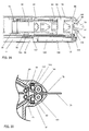
- FIG. 20 is an overhead diagram showing a state in which case member 29c of measurer 29' abuts against biological information detection sensor feeding apparatus 28 (attached state).
- FIG. 20 contains a cross-sectional diagram of biological information detection sensor feeding apparatus 28' and a top diagram of measurer 29', In FIG. 20 , some reference signs are the same as in FIG. 19 , and therefore are omitted.
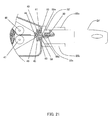
- FIG. 21 is an enlarged lateral cross-sectional diagram of sensor loading section 32' and the surroundings in a state in which case member 29c of measurer 29' abuts against biological information detection sensor feeding apparatus 28' (attached state).
- member 29c of measurer 29' abuts against biological information detection sensor feeding apparatus 28' (attached state).
- FIG. 21 as for measurer 29', only a region of sensor loading section 32' thereof is shown as a cross-sectional diagram.
- Sensor loading section 32' has contact 32a that is a contacting terminal to blood glucose sensor 30.
- Blood glucose sensor 30 is loaded into sensor loading section 32' of measurer 29', and thereby, contacts with contact 32a. Thereby, blood glucose sensor 30 is electrically connected with a measuring circuit in measurer 29' through contact 32a.
- the attaching position of measurer 29' is appropriately regulated by attachment 28a, angle (receiving portion) 28b, end surface portion 28c and the like that define sensor feeding space 42' of biological information detection sensor feeding apparatus 28'.
- blood glucose sensor 30 is properly loaded into sensor loading section 32 of measurer 29'. That is, blood glucose sensor 30 can appropriately contact with contact 32a in sensor loading section 32'.
- Blood glucose sensor 30 is set apart from biological information detection sensor feeding apparatus 28', while contacting with contact 32a of sensor loading section 32'.
- attachment 28a and the like that regulate measurer 29' are provided in biological information detection sensor feeding apparatus 28', and thereby, it is possible to provide biological information detection sensor feeding apparatus 28 that securely loads blood glucose sensor 30 into measurer 29' having sensor loading section 32' that is provided in the interior of the housing of measurer 29'.
- the attaching position of measurer 29' is regulated by attachment 28a, angle (receiving portion) 28b and end surface portion 28c.
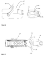
- the attaching position of measurer 29' is regulated by end surface portion 28c and lower-surface receiving portion 28d (see FIG. 23 and FIG. 24 ).
- biological information detection sensor feeding apparatus 28" according to Modification 2 of Embodiment 2 which has end surface portion 28c having an end surface similarly to the above-described biological information detection sensor feeding apparatus 28' according to Modification 1 of Embodiment 2, but does not have attachment 28a in the above-described Modification 1 and has lower-surface receiving portion 28d instead.
- Other configurations of biological information detection sensor feeding apparatus 28" are the same as the above-described biological information detection sensor feeding apparatus 28', and therefore, descriptions thereof are omitted.
- measurer 29' according to Modification 2 of Embodiment 2 has the same configuration as measurer 29' according to Modification 1 of Embodiment 2.
- end surface portion 28c having an end surface, lower-surface receiving portion 28d and the like.
- end surface portion 28c has an end surface that abuts against case member 29c of measurer 29', and is disposed close to fed blood glucose sensor 30. Since the end surface of end surface portion 28c abuts against case member 29c of measurer 29', it is possible to regulate measurer 29' in the loading direction of measurer 29'.
- end surface portion 28c has a curved concave end surface
- case member 29c has a convex end surface.
- Lower-surface receiving portion 28d supports the lower surface of measurer 29' to be attached.
- Lower-surface receiving portion 28d is provided at a lower portion of end surface portion 28c. Thereby, lower-surface receiving portion 28d can regulate the attaching position of measurer 29' in the vertical direction of measurer 29'.
- FIG. 24 is an enlarged lateral cross-sectional diagram of sensor loading section 32' and the surroundings in a state in which the end surface of case member 29c of measurer 29' abuts against the end surface of end surface portion 28c of biological information detection sensor feeding apparatus 28" according to Modification 2 of Embodiment 2 (attached state).
- FIG. 24 as for measurer 29', only a region of sensor loading section 32' is shown as a cross-sectional diagram.
- Sensor loading section 32 has contact 32a that is a contacting terminal to blood glucose sensor 30.
- Blood glucose sensor 30 is loaded into sensor loading section 32' of measurer 29', and thereby, contacts with contact 32a. Thereby, blood glucose sensor 30 is electrically connected with a measuring circuit in measurer 29' through contact 32a.
- the attaching position of measurer 29' is appropriately regulated by end surface portion 28c and lower-surface receiving portion 28d.
- blood glucose sensor 30 is appropriately loaded into sensor loading section 32' of measurer 29', That is, blood glucose sensor 30 can securely contact with contact 32a in sensor loading section 32'.
- Blood glucose sensor 30 is set apart from biological information detection sensor feeding apparatus 28", while contacting with contact 32a of sensor loading section 32'.
- Biological information detection sensor feeding apparatus 28" according to Modification 2 of Embodiment 2 does not have attachment 28a. Thereby, biological information detection sensor feeding apparatus 28" has a simple configuration and can be downsized. Therefore, biological information detection sensor feeding apparatus 28" according to Modification 2 of Embodiment 2 makes it possible to improve the portability, while maintaining the convenience in biological information detection sensor feeding apparatuses 28, 28'.
- FIG. 25 shows biological information detection sensor feeding apparatus 67 according to Embodiment 3.
- Biological information detection sensor feeding apparatus 67 which is used while being constantly placed on a planar surface such as for example, a desk, has a function to measure a blood glucose level (an example of biological information).
- Bio information detection sensor feeding apparatus 67 has body case 68 molded in an approximately cuboidal shape. As shown in FIG. 26 , biological information detection sensor feeding apparatus 67 is configured such that lid 69 at the rear end of body case 68 is opened and sensor cartridge 70 is stored in the interior thereof.
- Power button 71 is provided at the rear end side of the upper surface of body case 68, and, displaying section 72, set button 73 for blood glucose sensor 75 (see FIG. 27 ) and disposition button 74 for blood glucose sensor 75 are provided at the center portion.
- blood glucose sensor 75 of sensor cartridge 70 is fed to loading opening 76 provided at the front-end surface of body case 68, as shown in FIG. 25 (the details will be described later).
- blood glucose sensor 75 is stored in strip-shaped sensor feeding film 77.
- Sensor feeding film 77 includes strip-shaped holding film 78 and strip-shaped covering film 79 that covers a surface of this holding film 78.
- Blood glucose sensor 75 is disposed between strip-shaped holding film 78 and strip-shaped covering film 79. That is, on the surface of holding film 78, multiple (in the embodiment, 200) blood glucose sensors 75 are arranged at a predetermined interval along the longitudinal direction. Thus, blood glucose sensor 75 is held while being sandwiched between holding film 78 and covering film 79. As shown in FIG. 27 and FIG. 29 , Embodiment 3 differs from the above-described Embodiment 1 in the orientation of blood glucose sensor 75 that is being stored in sensor feeding fihn 77, but has the same orientation as Embodiment 2.
- Blood glucose sensor 75 has an approximately triangular and thin-plate shape. Spot-application portion 80 on which blood is to be spot-applied is provided near one apex of the triangle, and connecting electrodes 81 are provided from the end opposite to spot-application portion 80 to the center portion.
- Feed guide holes 82 are provided at both ends in the direction orthogonal to the longitudinal direction of sensor feeding film 77. Feed guide holes 82 are holes for feeding sensor feeding film 77 to loading opening 76.
- Sensor feeding film 77 is stored in sensor cartridge 70 ( FIG. 26 ). Furthermore, Sensor cartridge 70 is stored in body case 68.
- FIG. 28 is lateral a cross-sectional diagram of biological information detection sensor feeding apparatus 67 when sensor cartridge 70 is stored in body case 68
- FIG. 29 is an overhead cross-sectional diagram thereof.
- sensor cartridge 70 The internal configuration of sensor cartridge 70 will be described. As shown in FIG. 28 , a roll of sensor feeding film 77 is stored in storage section 83 provided at the center portion in the interior of sensor cartridge 70. Sensor feeding film 77 is loosely wound so that blood glucose sensor 75 held in sensor feeding film 77 is not damaged.
- the roll of sensor feeding film 77 is disposed such that the longitudinal direction of sensor feeding film 77 is oriented to the front-end of sensor cartridge 70.
- Sensor cartridge 70 is disposed such that feeding opening 84 thereof opposes loading opening 76.
- sensor feeding film 77 in which from the bottom in the drawing, holding film 78, blood glucose sensor 75 and covering film 79 are sequentially laminated, is fed toward feeding opening 84.
- Blood glucose sensor 75 is held in holding film 78, with spot-application portion 80 side being oriented to feeding opening 84.
- Sensor loading section 85 for loading blood glucose sensor 75 is provided between feeding opening 84 of sensor cartridge 70 and loading opening 76.
- cylindrical separating pulleys 86, 87 are provided at portions opposite to feeding opening 84. Furthermore, a pair of cylindrical pressing pulleys 88, 89 is provided at the inward side of separating pulleys 86, 87 (at the upstream side in the feeding direction of sensor feeding film 77).
- the axial length of pressing pulleys 88, 89 is greater than the short-directional width of sensor feeding film 77. Therefore, pressing pulleys 88, 89 can press the whole of the short-directional width of sensor feeding film 77. Thereby, pressing pulleys 88, 89 correct peculiar windings of sensor feeding film 77 wound in a roll form, and then send it to separating pulleys 86, 87 at the downstream side.
- Separating pulleys 86, 87 separate covering film 79 and holding film 78 from sensor feeding film 77.
- Covering film 79 is returned upward and subsequently rearward by separating pulley 86, and through cylindrical guiding pulleys 90, 91 and cylindrical driving reel 92, is wound by cylindrical winding reel 93 (winding mechanism).
- the axial lengths of separating pulley 86, guiding pulleys 90, 91 and driving reel 92 are greater than the short-directional width of sensor feeding film 77.
- holding film 78 is returned downward and subsequently rearward by separating pulley 87, and through cylindrical guiding pulleys 94, 95 and cylindrical driving reel 96, is wound by cylindrical winding reel 97.
- the axial lengths of separating pulley 87, guiding pulleys 94, 95 and driving reel 96 are greater than the short-directional width of sensor feeding film 77.
- Driving projections 92a, 96a are provided at both end sides of driving reels 92, 96. Driving projections 92a, 96a engage with feed guide holes 82 provided at both ends of sensor feeding film 77. Furthermore, driving reels 92, 96 are coupled with driving motor 98 (see FIG. 29 ) in body case 68 through connecting gear 70A (see FIG. 26 ).
- a winding mechanism for covering film 79 of sensor feeding film 77 is constituted by driving motor 98, connecting gear 70A, winding reel 93, driving reel 92, guiding pulleys 91, 90 and separating pulley 86.
- a winding mechanism for holding film 78 of sensor feeding film 77 is constituted by driving motor 98, connecting gear 70A, winding reel 97, driving reel 96, guiding pulleys 95, 94 and separating pulley 87.
- Winding reel 93 has the same slipping clutch mechanism as Embodiment 1, and is connected with driving reel 92.
- Winding reel 97 has the same slipping clutch mechanism as Embodiment 1, and is connected with driving reel 96.
- FIG. 30 is an enlarged lateral cross-sectional diagram of sensor loading section 85
- FIG. 31 is an enlarged overhead cross-sectional diagram of sensor loading section 85.
- sensor loading section 85 has electrode roller 100 to be disposed on one surface side (the upper side in FIG. 30 ) of blood glucose sensor 75.
- Electrode roller 100 has roller electrodes 99 to be connected with connecting electrodes 81 of blood glucose sensor 75 (see FIG. 31 ).
- roller electrodes 99 are provided on both end portions of the outer periphery of electrode roller 100.
- sensor loading section 85 has pressing roller 101 disposed on the other surface side (the lower side in FIG 30 ) of blood glucose sensor 75. Pressing roller 101 presses blood glucose sensor 75 to electrode roller 100 side. For example, the rotating shaft portion of pressing roller 101 is pressed to electrode roller 100 side by a flat spring (an example of biasing member, not shown in the figure).
- a flat spring an example of biasing member, not shown in the figure.
- Optical sensor (an example of sensor detecting section) 102 is provided between feeding opening 84 and electrode roller 100. Optical sensor 102 detects blood glucose sensor 75 entered into sensor loading section 85.
- roller electrodes 99 contact with metallic connecting terminals 103. Roller electrodes 99 are connected with measuring section 104 (see FIG. 32 ) through metallic connecting terminals 103.
- FIG 32 is a control block diagram of biological information detection sensor feeding apparatus 67.
- Measuring section 104 is connected with control section 105.
- Control section 105 is connected with motor controller 106.
- Optical sensor 102 (see FIG 30 ) is connected with motor controller 106.
- Optical sensor 102 and connecting terminals 103 are disposed on a printed board.
- Driving motor 98 that drives connecting gear 70A of sensor cartridge 70 is connected with motor controller 106.
- the driving force of driving motor 98 is transmitted to sensor sending gear 107 (see FIG. 29 ) through connecting gear 70A of sensor cartridge 70, and further is transmitted to driving reel 92.
- driving motor 108 that drives electrode roller 100 is connected with motor controller 106.
- the driving force of driving motor 108 is transmitted to electrode roller 100 through connecting gear 109, and electrode roller 100 transports blood glucose sensor 75.
- cartridge detecting switch 69A that detects that sensor cartridge 70 has been stored in body case 68, ROM 110 in which programs in the control section are stored, battery 111, displaying section 72, power button 71, set button 73 for the sensor, and disposition button 74 for the sensor are connected with control section 105.
- a user opens lid 69 at the rear end of body case 68, and loads sensor cartridge 70 to the interior of body case 68.
- control section 105 detects that sensor cartridge 70 is being loaded to body case 68, using cartridge detecting switch 69A. Thereafter, once the user (nurse) depresses set button 73 for the sensor, blood glucose sensor 75 of sensor cartridge 70 appears while being loaded into loading opening 76.
- control section 105 that has detected the depression of set button 73, rotates driving motor 98 (see FIG. 29 ) by a predetermined amount, using motor controller 106. Then, the driving force of driving motor 98 is transmitted to driving reel 92 (see FIG. 28 ), through sensor sending gear 107 and connecting gear 70A.
- Driving projections 92a of driving reel 92 transmit driving force to covering film 79 through feed guide holes 82 of covering film 79.
- covering film 79 is pulled out from storage section 83 to feeding opening 84 side by a predetermined amount corresponding to the rotation amount of driving motor 98, by the winding mechanism for covering film 79 (driving motor 98, connecting gear 70A, winding reel 93, driving reel 92, guiding pulleys 91, 90, and separating pulley 86).
- Driving projections 96a of driving reel 96 transmit driving force to holding film 78 through feed guide holes 82 of holding film 78.
- holding film 78 is pulled out from storage section 83 to feeding opening 84 side by a predetermined amount corresponding to the rotation amount of driving motor 98, by the winding mechanism for holding film 78 (driving motor 98, connecting gear 70A, winding reel 97, driving reel 96, guiding pulleys 95, 94, and separating pulley 87).
- covering film 79 and holding film 78 are pulled out to feeding opening 84 side by the same predetermined amount.
- sensor feeding film 77 is pulled out by the predetermined amount.
- covering film 79 and holding film 78 are separated from sensor feeding film 77 by separating pulleys 86, 87. Then, one blood glucose sensor 75 is uncovered from holding film 78.
- the biological information detection sensor feeding apparatus is configured to automatically load blood glucose sensor 75 to loading opening 76. Specifically, first, by the driving force of separating pulleys 86, 87, uncovered blood glucose sensor 75 is entered into sensor loading section 85 through feeding opening 84 of sensor cartridge 70 (see FIG. 30 ).
- optical sensor 102 of sensor loading section 85 detects entered blood glucose sensor 75.
- motor controller 106 drives driving motor 108.
- the driving force of driving motor 108 is transmitted to electrode roller 100 through connecting gear 109.
- blood glucose sensor 75 reaches between electrode roller 100 and pressing roller 101.
- blood glucose sensor 75 is led to loading opening 76 by the driving force of electrode roller 100.
- optical sensor 102 becomes unable to detect blood glucose sensor 75.
- motor controller 106 stops the driving of driving motor 108.
- roller electrodes 99 at both end portions of electrode roller 100 are abutted against and electrically connected to the connecting electrodes of blood glucose sensor 75 entered to the predetermined position.
- the loading of blood glucose sensor 75 into sensor loading section 85 is completed.
- Spot-application portion 80 of loading-completed blood glucose sensor 75 is in a state of being uncovered to the exterior of body case 68 through loading opening 76 (see FIG. 25 ).
- a finger of a patient is punctured with a separately-prepared puncture instrument. Once the blood flowed out by pucturing is spot-applied on spot-application portion 80 of blood glucose sensor 75, the blood glucose level is measured by measuring section 104 and the result is displayed on displaying section 72.
- Control section 105 that has detected the depression of disposition button 74, rotates driving motor 98 using motor controller 106. Then, electrode roller 100 rotates and disposes blood glucose sensor 75 out of body case 68.
- driving motor 108 is coupled with electrode roller 100, but driving motor 108 only has to be coupled with at least one of electrode roller 100 and pressing roller 101.
- biological information detection sensor feeding apparatus 67 has the following features.
- measuring section 104 measures the blood glucose level.
- the present invention is expected to be widely applied as a biological information detection sensor feeding apparatus that feeds a biological information detection sensor such as a blood glucose sensor, for example.
Landscapes
- Health & Medical Sciences (AREA)
- Life Sciences & Earth Sciences (AREA)
- Physics & Mathematics (AREA)
- Engineering & Computer Science (AREA)
- Biomedical Technology (AREA)
- General Health & Medical Sciences (AREA)
- Pathology (AREA)
- Chemical & Material Sciences (AREA)
- Molecular Biology (AREA)
- Biophysics (AREA)
- Optics & Photonics (AREA)
- Immunology (AREA)
- Analytical Chemistry (AREA)
- General Physics & Mathematics (AREA)
- Biochemistry (AREA)
- Veterinary Medicine (AREA)
- Surgery (AREA)
- Medical Informatics (AREA)
- Public Health (AREA)
- Emergency Medicine (AREA)
- Animal Behavior & Ethology (AREA)
- Heart & Thoracic Surgery (AREA)
- Hematology (AREA)
- Urology & Nephrology (AREA)
- Food Science & Technology (AREA)
- Medicinal Chemistry (AREA)
- Measurement Of The Respiration, Hearing Ability, Form, And Blood Characteristics Of Living Organisms (AREA)
- Automatic Analysis And Handling Materials Therefor (AREA)
- Investigating Or Analysing Biological Materials (AREA)
Abstract
Description
- The present invention relates to a biological information detection sensor feeding apparatus. More specifically, the present invention relates to a biological information detection sensor feeding apparatus that feeds a biological information detection sensor such as a blood glucose sensor, for example.
- A conventional biological information detection sensor feeding apparatus includes, for example, a body case having a feeding opening for a test element (an example of a biological information detection sensor); a storage section that stores a strip-shaped sensor feeding film in the body case; and a feeding section that feeds a predetermined length of the sensor feeding film from the storage section to the feeding opening. The feeding section is configured to feed a predetermined length of the sensor feeding film to the feeding opening, and immediately before the feeding opening, peel a covering film from a surface of a holding film constituting the sensor feeding film (see PTL 1).
- Japanese Unexamined Patent Application Publication (Translation of PCT Application) No.
2007-535351 - In the conventional configuration, one biological information detection sensor (an example of a test element) is fed to the feeding opening. However, when taking the biological information detection sensor fed to the feeding opening, the user may unwittingly contaminate the biological information detection sensor by dropping.
- Since biological information detection sensors are used for measuring biological samples, it is undesirable to a contaminated biological information detection sensor. Consequently, it is necessary to take out a new sensor from the biological information detection sensor feeding apparatus, again. Thus, the conventional biological information detection sensor feeding apparatus suffers from poor usability. Hence, an object of the present invention is to provide a biological information detection sensor feeding apparatus that is easy to use.
- To achieve the above-described object, a biological information detection sensor feeding apparatus according to
Embodiment 1 of the present invention includes: a body case having a feeding stage; a storage section that stores a strip-shaped sensor feeding film in the body case, the sensor feeding film including a biological information detection sensor, and a holding film and a covering film that sandwich the biological information detection sensor; and a feeding section that feeds the biological information detection sensor from the storage section to the feeding stage. The feeding section is configured to feed the holding film of the sensor feeding film and the biological information detection sensor to the feeding stage, and peel the covering film from the sensor feeding film before feeding the biological information detection sensor to the feeding stage, and is configured to wind the holding film fed to the feeding stage. The feeding stage inclines downward along a feeding direction of the sensor feeding film. - To achieve the object, a biological information detection sensor feeding apparatus according to
Embodiment 2 of the present invention includes: a body case having a feeding opening configured such that a biological information measurer can be attached thereto; a storage section that stores a strip-shaped sensor feeding film in the body case, the sensor feeding film including a biological information detection sensor, and a holding film and a covering film that sandwich the biological information detection sensor; and a feeding section that feeds the biological information detection sensor from the storage section to the feeding opening. The feeding section is configured to feed the biological information detection sensor to the feeding opening, and separate the holding film and the covering film from the sensor feeding film before feeding the biological information detection sensor to the feeding opening. The feeding section is configured to load the biological information detection sensor fed to the feeding opening, into the biological information measurer attached to the feeding opening. - To achieve the above-described object, a biological information detection sensor feeding apparatus according to
Embodiment 3 of the present invention includes: a measuring section that measures biological information; a body case having a loading opening; a storage section that stores a strip-shaped sensor feeding film in the body case, the sensor feeding film including a biological information detection sensor, and a holding film and a covering film that sandwich the biological information detection sensor; and a feeding section that feeds the biological information detection sensor from the storage section to the loading opening. The feeding section is configured to feed the biological information detection sensor to the loading opening, and separate the holding film and the covering film from the sensor feeding film before feeding the biological information detection sensor to the loading opening. The loading opening includes a connector connected with the measuring section and the biological information detection sensor includes a connecting electrode, and the feeding section is configured to feed the biological information detection sensor to the loading opening such that the connecting electrode of the biological information detection sensor is electrically connected with the connecter of the loading opening. - In accordance with a biological information detection sensor feeding apparatus according to the present invention, it is possible to easily load a biological information detection sensor into a biological information measurer and to simplify the measurement of biological information.
-
-
FIG. 1 is a perspective diagram of a biological information detection sensor feeding apparatus according toEmbodiment 1; -
FIG 2 is a perspective diagram of a roll of a sensor feeding film of the biological information detection sensor feeding apparatus according toEmbodiment 1; -
FIG. 3A is a lateral cross-sectional diagram of the biological information detection sensor feeding apparatus according toEmbodiment 1; -
FIG. 3B is an enlarged lateral cross-sectional diagram of the principal part around a feeding stage of the biological information detection sensor feeding apparatus according toEmbodiment 1; -
FIG. 4 is a perspective top diagram of the biological information detection sensor feeding apparatus according toEmbodiment 1; -
FIG. 5 is a cross-sectional diagram of the principal part of a winding reel constituting a winding mechanism of the biological information detection sensor feeding apparatus according toEmbodiment 1; -
FIG. 6 is a perspective diagram of a biological information detection sensor feeding apparatus according toEmbodiment 2; -
FIG. 7 is a perspective diagram of a sensor feeding film of the biological information detection sensor feeding apparatus according toEmbodiment 2; -
FIG. 8 is an enlarged diagram of the principal part of a feeding opening of the biological information detection sensor feeding apparatus according toEmbodiment 2; -
FIG. 9 is a lateral cross-sectional diagram of the biological information detection sensor feeding apparatus according toEmbodiment 2; -
FIG. 10 is a perspective top diagram of the biological information detection sensor feeding apparatus according toEmbodiment 2; -
FIG. 11 is a lateral cross-sectional diagram of the principal part in the vicinity of the feeding opening of the biological information detection sensor feeding apparatus according toEmbodiment 2; -
FIG. 12 is a perspective diagram of the principal part of the feeding opening of the biological information detection sensor feeding apparatus according toEmbodiment 2; -
FIG. 13 is a perspective diagram of the principal part of the feeding opening of the biological information detection sensor feeding apparatus according toEmbodiment 2; -
FIG. 14 is a lateral cross-sectional diagram of the principal part of the feeding opening of the biological information detection sensor feeding apparatus according toEmbodiment 2; -
FIG. 15 is a lateral cross-sectional diagram of the principal part of the feeding opening of the biological information detection sensor feeding apparatus according toEmbodiment 2; -
FIG. 16 is a lateral cross-sectional diagram of the principal part of the feeding opening of the biological information detection sensor feeding apparatus according toEmbodiment 2; -
FIG. 17 is a lateral cross-sectional diagram of the principal part of the feeding opening of the biological information detection sensor feeding apparatus according toEmbodiment 2; -
FIG. 18 is a perspective diagram of a biological information detection sensor feeding apparatus according toModification 1 ofEmbodiment 2; -
FIG. 19 is a perspective top diagram of the biological information detection sensor feeding apparatus according toModification 1 ofEmbodiment 2; -
FIG. 20 is a perspective top diagram of the biological information detection sensor feeding apparatus (in a docked state) according toModification 1 ofEmbodiment 2; -
FIG. 21 is an enlarged lateral cross-sectional diagram of the principal part of the biological information detection sensor feeding apparatus (in the docked state) according toModification 1 ofEmbodiment 2; -
FIG. 22 is a perspective diagram of a biological information detection sensor feeding apparatus according toModification 2 ofEmbodiment 2; -
FIG 23 is a perspective top diagram of the biological information detection sensor feeding apparatus according toModification 2 ofEmbodiment 2; -
FIG. 24 is an enlarged lateral cross-sectional diagram of the principal part of the biological information detection sensor feeding apparatus (in the docked state) according toModification 2 ofEmbodiment 2; -
FIG. 25 is a perspective diagram of a biological information detection sensor feeding apparatus according toEmbodiment 3; -
FIG. 26 is an exploded perspective diagram of the biological information detection sensor feeding apparatus according toEmbodiment 3; -
FIG. 27 is a perspective diagram of a sensor feeding film of the biological information detection sensor feeding apparatus according toEmbodiment 3; -
FIG. 28 is a lateral cross-sectional diagram of the biological information detection sensor feeding apparatus according toEmbodiment 3; -
FIG. 29 is a perspective top diagram of the biological information detection sensor feeding apparatus according toEmbodiment 3; -
FIG. 30 is an enlarged lateral cross-sectional diagram of the principal part of a loading opening of the biological information detection sensor feeding apparatus according toEmbodiment 3; -
FIG. 31 is an enlarged perspective diagram of the principal part of the loading opening of the biological information detection sensor feeding apparatus according toEmbodiment 3, viewed in the overhead direction; and -
FIG. 32 is a control block diagram of the biological information detection sensor feeding apparatus according toEmbodiment 3. - Hereinafter, an embodiment of the present invention will be described with reference to the accompanying drawings.
-
FIG. 1 shows biological information detectionsensor feeding apparatus 1. A user of biological information detectionsensor feeding apparatus 1 is a nurse in a hospital, for example. Biological information detectionsensor feeding apparatus 1 hasbody case 2 molded in an approximately cuboidal shape, and feedingstage 4 provided on the upper surface of the front-end side ofbody case 2. A biological information detection sensor (for example, blood glucose sensor 3) is fed to feedingstage 4. - Operating
lever 5 is provided at the rear side ofbody case 2. By an operation of operatinglever 5,blood glucose sensors 3 can be fed to feedingstage 4 one by one. - As shown in
FIG. 2 ,blood glucose sensor 3 is stored in strip-shapedsensor feeding film 6.Sensor feeding film 6 includes strip-shapedholding film 7 and strip-shapedcovering film 8 that covers a surface of holdingfilm 7. -
Blood glucose sensor 3 is stored between strip-shapedholding film 7 and strip-shapedcovering film 8. That is, on the surface of holdingfilm 7, multiple (in the embodiment, 200)blood glucose sensors 3 are arranged at a predetermined interval along the longitudinal direction of holdingfilm 7. The longitudinal direction of storedblood glucose sensors 3 is orthogonal to the longitudinal direction of holdingfilm 7, but is not particularly limited. - On the surface of holding
film 7, discrimination information is indicated in the vicinity of eachblood glucose sensor 3. The discrimination information is, for example, the holding number of eachblood glucose sensor 3. The holding numbers, which are given in the arrangement order ofblood glucose sensors 3, may be in the descending order (for example, from 200 to 1), or may be in the ascending order (for example, from 1 to 200). - At both ends in the direction orthogonal to the longitudinal direction of
sensor feeding film 6, there are provided feed guide holes 9 for feeding a predetermined length ofsensor feeding film 6 to feedingstage 4 inFIG. 1 . -
FIG. 3A is a cross-sectional diagram of biological information detectionsensor feeding apparatus 1 whenbody case 2 is viewed in the lateral direction;FIG. 3B is an enlarged cross-sectional diagram of biological information detectionsensor feeding apparatus 1 when the principal part around feedingstage 4 ofbody case 2 is viewed in the lateral direction; andFIG. 4 is a perspective diagram of biological information detectionsensor feeding apparatus 1 whenbody case 2 is viewed from the upper surface side. - As shown in
FIG. 3A , a roll ofsensor feeding film 6 is stored instorage section 10 provided in the interior ofbody case 2.Storage section 10 only has to be positioned near the center of the interior ofbody case 2. Preferably,sensor feeding film 6 is loosely wound in a roll so thatblood glucose sensor 3 held insensor feeding film 6 is not damaged. - As shown in
FIG. 3A andFIG. 4 , the roll ofsensor feeding film 6 is disposed such that the unwinding direction of the roll is oriented to feedingstage 4 in the vicinity of the front-end ofbody case 2. As shown inFIG. 3A ,sensor feeding film 6 is fed to feedingstage 4. Insensor feeding film 6 to be fed, holdingfilm 7,blood glucose sensor 3 and coveringfilm 8, from the bottom in the drawing, are sequentially laminated. - Feeding
stage 4 is connected with guidingsection 4a. Guidingsection 4a is a board withinbody case 2, and is positioned betweenstorage section 10 and feedingstage 4. Guidingsection 4a is a board for guidingsensor feeding film 6 to feedingstage 4. - Cylindrical pressing
pulley 11 is disposed above guidingsection 4a in the vicinity ofstorage section 10. The axial length of pressingpulley 11 is greater than the short-directional width ofsensor feeding film 6. Thereby, pressingpulley 11. can press the whole of the short-directional width ofsensor feeding film 6 onto guidingsection 4a. - In the interior of
body case 2, cylindrical separatingpulley 12 is provided above guidingsection 4a in the vicinity of feedingstage 4. Separatingpulley 12separates covering film 8 fromsensor feeding film 6. The separated covering film is returned upward and subsequently rearward, and through cylindrical guiding pulleys 13, 14 andcylindrical driving reel 15, is wound by windingreel 16. As understood fromFIG. 4 , the axis-directional lengths of separatingpulley 12, guidingpulleys reel 15 are longer than the short-directional width ofsensor feeding film 6. - Thus,
blood glucose sensor 3 uncovered on the surface of holdingfilm 7 is fed to feedingstage 4. The board area of feedingstage 4 is greater than the area ofblood glucose sensor 3. Thereby,blood glucose sensor 3 can be stably held on feedingstage 4.Blood glucose sensor 3 held on feedingstage 4 is obtained by a user. - As shown in
FIG. 3A , in the interior ofbody case 2, cylindrical returningpulley 17 is provided downstream of feeding stage 4 (downstream side in the feeding direction of sensor feeding film 6).Holding film 7 ofsensor feeding film 6 is returned downward and subsequently rearward by returningpulley 17, and through cylindrical guiding pulleys 18, 19 andcylindrical driving reel 20, is wound by windingreel 21. The axial lengths of returningpulley 17, guidingpulleys reel 20 are longer than the short-directional width ofsensor feeding film 6. - Driving
projections reels projections sensor feeding film 6. Drivingreels operating lever 5. - Thus, a winding mechanism for covering
film 8 ofsensor feeding film 6 is constituted by operatinglever 5, windingreel 16, drivingreel 15, guidingpulleys pulley 12. A winding mechanism for holdingfilm 7 ofsensor feeding film 6 is constituted by operatinglever 5, windingreel 21, drivingreel 20, guidingpulleys pulley 17. The winding mechanism for coveringfilm 8 and the winding mechanism for holdingfilm 7 are constituent members of the feeding section that feeds a biological information detection sensor. - Winding
reel 16 that constitutes the winding mechanism for coveringfilm 8 is provided so as to be connected with drivingreel 15, and has a slipping clutch mechanism. Windingreel 21 that constitutes the winding mechanism for holdingfilm 7 is provided so as to be connected with drivingreel 20, and has a slipping clutch mechanism. - The clutch mechanism of winding
reels FIG. 5 . Windingreel 16 shown inFIG. 5 hasreel spindle 22,Gear 23 is provided at one end ofreel spindle 22, andspring retainer 24 is provided at the other end. Aroundreel spindle 22,coil spring 25 is attached in a compression state. - Furthermore, around
reel spindle 22, reelingpart 26 is attached throughcoil spring 25. Bycoil spring 25, thegear 23 side end of reelingpart 26 is pressed ontogear 23 through slippingmember 27 composed of felt. When winding load with a predetermined value or more is applied to reelingpart 26, reelingpart 26 slips on slippingmember 27 and windingreel 16 runs idle. - Winding
reel 16 is connected with drivingreel 15 by gear 23 (seeFIG. 3A ), and windingreel 16 is configured to rotate 1.2 cycles when drivingreel 15rotates 1 cycle. Thereby, the rotation amount of windingreel 16 is more than the rotation amount of drivingreel 15. However, since the slipping clutch mechanism of windingreel 16 allows windingreel 16 to appropriately run idle, windingreel 16 can appropriately wind coveringfilm 8 to which an appropriate tension is given. - Winding
reel 21 to wind holdingfilm 7 can be configured in the same manner as windingreel 16. Accordingly, windingreel 21 can appropriately wind holdingfilm 7 to which an appropriate tension is given. - Operating
lever 5 is connected with drivingreel 20 and drivingreel 15 through a ratchet mechanism. InFIG. 1 , only when operatinglever 5 is pulled up rearward, drivingreel 20 and drivingreel 15 rotate in predetermined directions. The rotation amounts of drivingreel 20 and drivingreel 15 are set so as to correspond to the operation amount of operatinglever 5. - The operation of biological information detection
sensor feeding apparatus 1 having the above configuration in use will be described hereinafter. First, inFIG. 1 , a user (for example, a nurse) holds the upper surface of the front-end side ofbody case 2 with the right hand, for example, and pulls up operatinglever 5 rearward by a predetermined amount with the left hand. Then, corresponding to the operation of operatinglever 5, drivingreel 20 rotates in a predetermined direction (seeFIG. 3A ). Similarly, drivingreel 15 connected with drivingreel 20 also rotates in a predetermined direction. - Driving
projections 15a of drivingreel 15 transmit driving force to coveringfilm 8, through feed guide holes 9 of coveringfilm 8 that engage with drivingprojections 15a. Thereby, coveringfilm 8 is unwound fromstorage section 10 by a predetermined amount corresponding to the operation of operatinglever 5, by the winding mechanism for covering film 8 (operatinglever 5, windingreel 16, drivingreel 15, guidingpulleys - Driving
projections 20a of drivingreel 20 transmit driving force to holdingfilm 7, through feed guide holes 9 of holdingfilm 7 that engage with drivingprojections 20a. Thereby, holdingfilm 7 is unwound fromstorage section 10 by a predetermined amount corresponding to the operation of operatinglever 5, by the feeding section for holding film 7 (operatinglever 5, windingreel 21, drivingreel 20, guidingpulleys - That is, covering
film 8 and holdingfilm 7, which constitutesensor feeding film 6, are unwound by the same predetermined amount, in other words,sensor feeding film 6 is fed to feedingstage 4. - When
sensor feeding film 6 is fed to feedingstage 4, coveringfilm 8 is peeled from holdingfilm 7 by separatingpulley 12 provided above guidingsection 4a, and then is rolled upward,Cover film 8 is subsequently returned rearward, and through guidingpulleys reel 15, is wound by windingreel 16. - Once covering
film 8 is peeled from holdingfilm 7 by separatingpulley 12,blood glucose sensor 3, which has been sandwiched by holdingfilm 7 and coveringfilm 8, is uncovered. Then,blood glucose sensor 3 uncovered on the surface of holdingfilm 7 is fed to feedingstage 4. - As described above, feeding
stage 4 is configured such that the size thereof is greater than the size ofblood glucose sensor 3. Thereby,blood glucose sensor 3 is stably held on feedingstage 4, and does not drop out of feedingstage 4. - In order to pick up
blood glucose sensor 3 fed to feedingstage 4, for example, a user (a nurse) holdsblood glucose sensor 3 with the pulp of forefinger F of the right hand, slides and movesblood glucose sensor 3 along feeding stage 4 (rightward inFIG. 4 ), and then pulls it out to the exterior of feeding stage 4 (for example, the upper side or the lower side inFIG. 4 ). The user pinches with the forefinger and the thumb the upper and lower sides ofblood glucose sensor 3 pulled out of feedingstage 4 in this way. Thus,blood glucose sensor 3 can be stably picked up from feedingstage 4. - Particularly in the embodiment, as shown in
FIG 3B , preferably feedingstage 4 has incliningportion 4b that inclines downward along the feeding direction ofsensor feeding film 6. With incliningportion 4b, the returningpulley 17 side end of feedingstage 4 is disposed below the upper end of returningpulley 17. That is, the upper end of returningpulley 17 protrudes above the returningpulley 17 side end of feedingstage 4. - As shown in
FIG. 3B , incliningportion 4b gradually inclines downward along the feeding direction of sensor feeding film 6 (as going to returning pulley 17); the inclination angle of incliningportion 4b is not particularly limited. It is desirable that the inclination angle of incliningportion 4b be determined such thatblood glucose sensor 3 can be easily taken out, in consideration of the largeness of feedingstage 4, the length of incliningportion 4b, the size of the finger, the diameter length of returningpulley 17 and the like. - Thereby, the user can more stably pick up
blood glucose sensor 3 fed to feedingstage 4, compared to the case where feedingstage 4 does not have incliningportion 4b. That is, in order to pick upblood glucose sensor 3 from feedingstage 4 havinginclining portion 4b, for example, the user holds the upper surface ofblood glucose sensor 3 with the pulp of forefinger F of the right hand (seeFIG. 3B ), and then, slides and moves it downward (rightward inFIG. 4 ) along incliningportion 4b of feedingstage 4. Since feedingstage 4 has incliningportion 4b,blood glucose sensor 3 on the upper surface of feedingstage 4 is easily slid. In addition, it is possible to allow the longitudinal side end ofblood glucose sensor 3 to abut against returningpulley 17 protruding above feedingstage 4. Since the whole of the longitudinal side end ofblood glucose sensor 3 is allowed to abut against returningpulley 17,blood glucose sensor 3 can stably abut against returningpulley 17. - Thereafter, the user can pull out
blood glucose sensor 3 to the exterior of feeding stage 4 (for example, the upper side or the lower side inFIG. 4 ) along returningpulley 17. By pinching the upper and lower sides of this pulled-outblood glucose sensor 3 with the forefinger and the thumb, it is possible to pick upblood glucose sensor 3 more steadily from the feeding stage. - Furthermore, since feeding
stage 4 has incliningportion 4b, it is possible to utilize returningpulley 17 constituting the feeding stage for drop prevention ofblood glucose sensor 3, and to achieve a simplification of a configuration for drop prevention. As a result,blood glucose sensor 3 is not dropped, and it is possible to increase ease of use. - Furthermore, as described above, in the embodiment, simply by pulling up operating
lever 5,blood glucose sensor 3 can be fed to feedingstage 4 one by one. As shown inFIG. 4 , on the surface of holdingfilm 7 fed to feedingstage 4, the discrimination information ofblood glucose sensor 3 is printed in the vicinity ofblood glucose sensor 3 allowing the user to confirm (e.g., by visually) the identity ofblood glucose sensor 3. The discrimination information is, for example, the holding number (the number information of blood glucose sensor 3) that shows the holding order ofblood glucose sensor 3. The holding number is printed for eachblood glucose sensor 3, in the descending order (for example, from 200 to 1) or in the ascending order (for example, from 1 to 200). - The nurse thus checks the holding number by visual observation when picking up
blood glucose sensor 3 from feedingstage 4, and thereby confirms the number ofblood glucose sensors 3 remaining in the apparatus, thus facilitating the use of apparatus. - The discrimination information printed in the vicinity of
blood glucose sensor 3 is not limited to the above holding number; the discrimination information may be a code that shows the model, production lot number, usable period, destination and other information ofblood glucose sensor 3. Thereby, it is possible to increase safety in work for the blood test. - In
FIG. 4 and other drawings, a rotary lever is exemplified as operatinglever 5, but operatinglever 5 is not limited to a rotary lever, and may be a rotating operating lever with a handle, a sliding operating lever, or an operating button for electric operation. -
FIG. 6 shows biological information detectionsensor feeding apparatus 28 according toEmbodiment 2. Biological information detectionsensor feeding apparatus 28 feeds blood glucose sensor 30 (an example of a biological information detection sensor) shown inFIG. 7 , to measurer 29 that measures biological information (for example, blood glucose level). Specifically, once cubicsensor loading section 32 provided at the end ofmeasurer 29 is attached (inserted) to sensor feeding opening 31 (FIG. 8 ) provided at the front-end of biological information detectionsensor feeding apparatus 28, oneblood glucose sensor 30 is loaded intosensor loading section 32. The "loaded" means thatblood glucose sensor 30 is electrically connected to an electric circuit ofmeasurer 29. - Biological information detection
sensor feeding apparatus 28 has approximatelycuboidal body case 33. As shown inFIG. 8 and FIG. 9 , at the front-end side ofbody case 33, there is provided feedingopening 31 to which blood glucose sensor 30 (an example of a biological information detection sensor) is fed. - As shown in
FIG. 6 , at the rear side ofbody case 33, there is provided operatinglever 34 for feedingblood glucose sensor 30 to feedingopening 31 one by one. - As shown in
FIG. 7 ,blood glucose sensor 30 is stored in strip-shapedsensor feeding film 35.Sensor feeding film 35 is constituted by strip-shapedholding film 36 and strip-shapedcovering film 37 that covers a surface of holdingfilm 36. -
Blood glucose sensor 30 is stored between strip-shapedholding film 36 and strip-shapedcovering fihn 37. That is, on the surface of holdingfilm 36, multiple (in the embodiment, 200blood glucose sensors 30 are arranged at a predetermined interval along the longitudinal direction of holdingfilm 36. Thus,blood glucose sensor 30 is held while being sandwiched between holdingfilm 36 and coveringfilm 37. -
Blood glucose sensor 30 has a thin-plate shape. Spot-application portion 38 on which blood is to be spot-applied is provided on a protruding portion provided at one end, and connectingelectrodes 39 are provided from the center portion to the other side end. - Feed guide holes 40 are provided at both ends in the direction orthogonal to the longitudinal direction of
sensor feeding film 35. Through feed guide holes 40, driving force is transmitted tosensor feeding film 35, and a predetermined length ofsensor feeding film 35 is fed toward feedingopening 31 ofbody case 33. -
FIG. 9 is a cross-sectional diagram of biological information detectionsensor feeding apparatus 28 whenbody case 33 is viewed in the lateral direction.FIG. 10 is a perspective diagram of biological information detectionsensor feeding apparatus 28 whenbody case 33 is viewed in the overhead direction. For description of the interval mechanism,FIG. 10 shows a state in which the upper surface ofbody case 33 is removed. - As shown in
FIG. 9 , a roll ofsensor feeding film 35 is stored instorage section 41 ofbody case 33.Storage section 41 only has to be provided near the center of the interior ofbody case 33.Sensor feeding film 35 is loosely wound so thatblood glucose sensor 30 stored therein is not damaged. - As shown in
FIG. 9 andFIG. 10 , the roll ofsensor feeding film 35 is disposed such that the unwinding direction ofsensor feeding film 35 is oriented to feedingopening 31 provided at the front-end side ofbody case 33. As shown inFIG. 9 ,sensor feeding film 35, in which from the bottom in the drawing, holdingfilm 36,blood glucose sensor 30 and coveringfilm 37 are sequentially laminated, is fed toward feedingopening 31.Blood glucose sensor 30 is held on holdingfilm 36 such that connectingelectrodes 39 ofblood glucose sensor 30 fed tosensor feeding opening 31 opposessensor loading section 32. - As shown in
FIG. 9 ,body case 33 of biological information detectionsensor feeding apparatus 28 according to the embodiment has cuboidalsensor feeding space 42 that allows feedingopening 31 and the interior ofbody case 33 to communicate with each other. -
Sensor holding section 43 is provided at the inward side (the leftward side inFIG. 9 , the side opposite to feeding opening 31) ofsensor feeding space 42. Throughsensor holding section 43,blood glucose sensor 30 is fed tosensor feeding space 42. - The length from
sensor holding section 43 to feedingopening 31 ofsensor feeding space 42 is greater than the length of blood glucose sensor 30 (the length from the end of the spot-application portion 38 side to the end of the connectingelectrode 39 side). Thereby, the whole ofblood glucose sensor 30 held bysensor holding section 43 fits withinsensor feeding space 42, and it does not protrude from feedingopening 31 ofbody case 33. Therefore,blood glucose sensor 30 is not subject to a touch by a user (a nurse). - As shown in
FIG. 9 to FIG 11 , the vicinity of feedingopening 31 insensor feeding space 42 has a taper shape, and the opening area ofsensor feeding space 42 becomes larger outward. Thereby, the sensor loading section 32 (seeFIG. 6 ) ofmeasurer 29 is easily inserted tosensor feeding space 42. - In the inside of
body case 33, cylindrical separating pulleys 44, 45 are provided at a region opposite tosensor holding section 43. Furthermore, a pair of cylindricalpressing pulleys storage section 41 side) of separatingpulleys pulleys sensor feeding film 35, and press the whole of the short-directional width ofsensor feeding film 35. Pressingpulleys sensor feeding film 35, and send it to the gap between separatingpulleys - Separating pulleys 44, 45 separate
sensor feeding film 35 into coveringfilm 37 and holdingfilm 36. - Separating
pulley 44returns covering film 37 ofsensor feeding film 35 upward and subsequently rearward. Coveringfilm 37 is wound by cylindrical windingreel 51, through cylindrical guiding pulleys 48, 49 andcylindrical driving reel 50. As understood fromFIG. 10 , the axial lengths of separatingpulley 44, guidingpulleys reel 50 are greater than the short-directional width ofsensor feeding film 35. - On the other hand, separating
pulley 45returns holding film 36 ofsensor feeding film 35 downward and subsequently rearward. Holdingfilm 36 is wound by cylindrical windingreel 55, through cylindrical guiding pulleys 52, 53 andcylindrical driving reel 54. The axial lengths of separatingpulley 45, guidingpulleys reel 54 are greater than the short-directional width ofsensor feeding film 35. - Driving
projections reels projections sensor feeding film 35. Drivingreels lever 34. - That is, a winding mechanism for covering
film 37 ofsensor feeding film 35 is constituted by operatinglever 34, windingreel 51, drivingreel 50, guidingpulleys pulley 44. - A winding mechanism for holding
film 36 ofsensor feeding film 35 is constituted by operatinglever 34, windingreel 55, drivingreel 54, guidingpulleys pulley 45. - Winding
reel 51 has the same slipping clutch mechanism asEmbodiment 1, and is connected with drivingreel 50. Windingreel 55 has the same slipping clutch mechanism asEmbodiment 1, and is connected with drivingreel 54. - Operating
lever 34 is connected with drivingreel 50 and drivingreel 54 through a ratchet mechanism. Drivingreel 50 and drivingreel 54 rotate in predetermined directions, only when operatinglever 34 is pulled up rearward (seeFIG. 6 ). The rotation amounts of drivingreel 50 and drivingreel 54 correspond to the operation of operatinglever 34. - The operation of biological information detection
sensor feeding apparatus 28 having the above configuration in use will be described hereinafter. First, a user (a nurse), for example, holds the upper surface of the front-end side ofbody case 33 with the right hand, and pulls up operatinglever 34 rearward by a predetermined amount with the left hand (seeFIG. 6 ). Then, drivingreel 50 and drivingreel 54 rotate in predetermined directions by the amounts corresponding to the operation of operating lever 34 (seeFIG. 9 ). - Driving
projections 50a of drivingreel 50 transmit driving force to coveringfilm 37 through feed guide holes 40 of coveringfilm 37. As a result, coveringfilm 37 is pulled out fromstorage section 41 to feedingopening 31 side by a predetermined amount corresponding to the operation of operatinglever 34, by the winding mechanism for covering film 37 (operatinglever 34, windingreel 51, drivingreel 50, guidingpulleys - Driving
projections 54a of drivingreel 54 transmit driving force to holdingfilm 36 through feed guide holes 40 of holdingfilm 36. As a result, holdingfilm 36 is pulled out fromstorage section 41 to feedingopening 31 side by a predetermined amount corresponding to the operation of operatinglever 34, by the winding mechanism for holding film 36 (operatinglever 34, drivingreel 54, guidingpulleys pulley 45, and winding reel 55). - That is, covering
film 37 and holdingfilm 36 are pulled out to feedingopening 31 side by the same predetermined amount. In other words,sensor feeding film 35 is pulled out. Coveringfilm 37 and holdingfilm 36 are separated from pulled-outsensor feeding film 35 by separatingpulleys blood glucose sensor 30 stored insensor feeding film 35 is fed tosensor feeding space 42. -
FIG. 11 shows a state in which oneblood glucose sensor 30 has been fed tosensor feeding space 42.FIG 11 is an enlarged cross-sectional diagram of the vicinity of feedingopening 31. In the embodiment,blood glucose sensor 30 fed tosensor feeding space 42 can be stably held bysensor holding section 43. To describe more specifically,sensor holding section 43 has guidingopening 56 that is opened in an oblong shape. Guidingopening 56 is formed in a taper shape, in order to easily guideblood glucose sensor 30 to feedingopening 31 side. In order thatblood glucose sensor 30 can be sandwiched and held at the opening portion on feedingopening 31 side in guidingopening 56, the gap of the opening portion is nearly equal to, or slightly greater than the thickness ofblood glucose sensor 30. At feedingopening 31 side of guidingopening 56, there is provided sandwichingsection 57, which sandwichesblood glucose sensor 30 that has been guided to guidingopening 56 and moved to feedingopening 31 side. That is,sensor holding section 43 is constituted by guidingopening 56 andsandwiching section 57. - In guiding
opening 56, the opening area of the inward side (the leftward side inFIG. 11 , the side from guidingopening 56 to separatingpulleys 44, 45) ofbody case 33 is greater than the opening area of the outward side (the rightward side inFIG. 11 , the side from guidingopening 56 to feeding opening 31) ofbody case 33. Thereby,blood glucose sensor 30 to be fed can be securely led to the interior of guidingopening 56, and furthermore, can be appropriately guided to sandwichingsection 57. -
FIG. 12 andFIG. 13 are enlarged perspective diagrams of sandwichingsection 57, viewed from feedingopening 31 side. As shown inFIG. 12 andFIG. 13 , sandwichingsection 57 hasoblong sandwiching claws claws FIG. 11 ). The opposing portion between sandwichingclaws portions blood glucose sensor 30. As shown inFIG. 13 , abuttingportions blood glucose sensor 30. - Sandwiching
section 57 has rotatingshafts claws FIG. 11 , abuttingportions opening 31 than rotatingshafts section 57 sandwichesblood glucose sensor 30 at a position closer to feedingopening 31 than rotatingshafts - As shown in
FIG. 12 andFIG. 13 , rotatingshafts rotating cams portions section 57 can always sandwichblood glucose sensor 30 at the same position. - Furthermore, rotating
shaft 60 includesspring 62. Thereby,spring 62, rotatingcam 63 and rotatingcam 64 always bias sandwichingclaws portions - As shown in
FIG. 11 , abuttingportions opening 31 than rotatingshafts blood glucose sensor 30, which advances from rotatingshafts opening 31 side (from the left side to the right side inFIG. 11 ), can open sandwichingclaws claws blood glucose sensor 30. - On the other hand, if
blood glucose sensor 30 tries to retract from feedingopening 31 side to rotatingshafts FIG. 11 ), sandwichingclaws blood glucose sensor 30 and try to close, so that sandwichingclaws blood glucose sensor 30. Thereby,blood glucose sensor 30 does not retract from feedingopening 31 side to rotatingshafts FIG. 11 ). - When
blood glucose sensor 30, from a state shown inFIG 14 , is guided to guidingopening 56 and is fed tosensor feeding space 42, sandwichingsection 57 sandwiches the center portion ofblood glucose sensor 30, as shown inFIG. 15 . In addition, by the opening portion on feedingopening 31 side in guidingopening 56,blood glucose sensor 30 can be held by sandwiching. Thus,blood glucose sensor 30 can be held by the opening portion on feedingopening 31 side in guidingopening 56 while being sandwiched by sandwichingsection 57. Thereby, it is possible to stably keep the position ofblood glucose sensor 30 fed tosensor feeding space 42. - That is, although
blood glucose sensor 30 fed tosensor feeding space 42 is not held by separatingpulleys section 57 sandwiches the center portion ofblood glucose sensor 30, and guidingopening 56 holds one side ofblood glucose sensor 30. Therefore,blood glucose sensor 30 can be stably held insensor feeding space 42. - Thereafter, as shown in
FIG. 16 , a user (a nurse) attaches (inserts) sensor loading section 32 (seeFIG. 10 ) ofmeasurer 29 from feedingopening 31 tosensor feeding space 42. Then, connectingelectrodes 39 ofblood glucose sensor 30 held insensor feeding space 42 are mechanically and electrically connected toconnector 65 insensor loading section 32. When insertingsensor loading section 32 tosensor feeding space 42,sensor loading section 32 would push backblood glucose sensor 30. However, as described above, sandwichingclaws blood glucose sensor 30, and thereforeblood glucose sensor 30 is not pushed back. Thereby,blood glucose sensor 30 can be appropriately connected toconnector 65. - As shown in
FIG. 7 ,blood glucose sensor 30 has guidingcutouts 66 provided by cutting out the end of the connectingelectrode 39 side. By guidingcutouts 66,blood glucose sensor 30 is guided toconnector 65 so that connectingelectrodes 39 can be appropriately connected toconnector 65. - Finally, as shown in
FIG. 17 , the user (nurse) pulls outsensor loading section 32 from feedingopening 31. Insensor loading section 32 of pulled-outmeasurer 29,blood glucose sensor 30 has been loaded. - When inserting
sensor loading section 32 ofmeasurer 29 tosensor feeding space 42, sandwichingclaws blood glucose sensor 30. Thereafter, by pulling outsensor loading section 32 ofmeasurer 29 fromsensor feeding space 42, the sandwiching between sandwichingclaws blood glucose sensor 30 is released. As a result, as shown inFIG. 17 ,blood glucose sensor 30 is securely transferred tomeasurer 29. - Naturally,
connector 65 ofsensor loading section 32 is configured to connect with connectingelectrodes 39 ofblood glucose sensor 30 while being pressed thereon, whenblood glucose sensor 30 is inserted tosensor loading section 32. This stabilizes the electric connecting condition betweenconnector 65 and connectingelectrodes 39, and results in a more secure loading ofblood glucose sensor 30 intoblood glucose sensor 30. - As described above, biological information detection
sensor feeding apparatus 28 according to the embodiment has the following features. - (1) The apparatus includes
body case 33 having feeding opening 31 for blood glucose sensor 30 (biological information detection sensor),storage section 41 that stores strip-shapedsensor feeding film 35 inbody case 33, and the feeding section that feeds a predetermined length ofsensor feeding film 35 fromstorage section 41 to feedingopening 31.
Sensor feeding film 35 has strip-shapedholding film 36, strip-shapedcovering film 37 covering the surface of holdingfilm 36, and multipleblood glucose sensors 30 that are sandwiched and held by holdingfilm 36 and coveringfilm 37.
The feeding section is configured to feed a predetermined length ofsensor feeding film 35 to feedingopening 31, to separate holdingfilm 36 and coveringfilm 37 immediately before feedingopening 31, and to feedblood glucose sensor 30 to feedingopening 31 side.
Furthermore, in feedingopening 31,sensor holding section 43 that holdsblood glucose sensor 30 is provided at the inward side ofbody case 33.Sensor holding section 43 includes guidingopening 56 that guidesblood glucose sensor 30 to feedingopening 31 side, and sandwichingsection 57 that sandwichesblood glucose sensor 30 guided by guidingopening 56 and moved to feedingopening 31 side. - (2)
Sandwiching section 57 includes sandwichingclaw 58 and sandwichingclaw 59 that sandwich the top and bottom surfaces ofblood glucose sensor 30. Sandwichingclaw 58 and sandwichingclaw 59 have abuttingportion 58a and abutting portion 58b that abut againstblood glucose sensor 30, androtating shaft 60 androtating shaft 61 that rotate sandwichingclaw 58 and sandwichingclaw 59. Abuttingportion 58a and abutting portion 58b are disposed closer to feedingopening 31 than rotatingshafts - (3) The rotating shafts of sandwiching
claw 58 and sandwichingclaw 59 are configured to abut againstrotating cam 63 and rotatingcam 64, respectively. - Thereby, in the embodiment, when taking out
blood glucose sensor 30, holdingfilm 36 and coveringfilm 37 are separated fromsensor feeding film 35, and, one newblood glucose sensor 30 is uncovered and then fed to feedingopening 31 through guidingopening 56 so as to fit withinsensor feeding space 42. Then,blood glucose sensor 30 fed to feedingopening 31 is sandwiched and held by sandwichingsection 57 ofsensor holding section 43. - When
blood glucose sensor 30 is being held by sandwichingsection 57 ofsensor holding section 43, oncemeasurer 29 is attached (inserted) from feedingopening 31 tosensor feeding space 42,blood glucose sensor 30 is loaded intomeasurer 29. - That is, according to the embodiment, a user himself does not need to peel
sensor feeding film 35 in order to take outblood glucose sensors 30 fromsensor feeding film 35 one by one. In addition, according to the embodiment, it is also possible to loadblood glucose sensor 30 intomeasurer 29 without touchingblood glucose sensor 30 by hand. Thus, the embodiment makes it possible to easily loadblood glucose sensor 30 intomeasurer 29, and therefore is easy to use. - As shown in
FIG. 7 andFIG. 10 ,Embodiment 2 differs from the above-describedEmbodiment 1 in the orientation ofblood glucose sensor 30 that is being stored insensor feeding film 35. This is because a main object ofEmbodiment 1 is to securely and easily take outblood glucose sensor 3 with fingers or the like, whereas a main object ofEmbodiment 2 is to directly loadblood glucose sensor 30 intoloading section 32 ofmeasurer 29. - In
Embodiment 2, sincemeasurer 29 hassensor loading section 32 protruding from the housing ofmeasurer 29, it is possible to regulate the attaching position ofmeasurer 29 by conforming the shape ofsensor loading section 32 tosensor feeding space 42. In contrast, biological information detection sensor feeding apparatus 28' according toModification 1 ofEmbodiment 2 supplies biologicalinformation detection sensor 30 to measurer 29' that has sensor loading section 32' provided in the interior of the housing of the measurer, unlikesensor loading section 32 of the above-describedmeasurer 29. - As shown in
FIGS 18 to 21 , measurer 29' has displayingsection 29a that displays measured values and the like, operatingsection 29b that is constituted by various buttons, and sensor loading section 32' into which biologicalinformation detection sensor 30 is to be loaded. Biological information detection sensor feeding apparatus 28' has the same configuration as the above-described biological information detectionsensor feeding apparatus 28, and further hasattachment 28a and endsurface portion 28c having an end surface. - As shown in
FIG. 18 , measurer 29' hasoperating section 29b.Operating section 29b, which is provided on the upper surface of measurer 29', includes a setting button by which setting data are set or selection menus are determined, a selection button by which a menu to be selected or a content to be displayed is switched, and a power button disposed on a side surface of measures 29'. - Sensor loading section 32' of measurer 29' is provided at an end of the housing of measurer 29' and that abuts against biological information detection sensor feeding apparatus 28'. Once sensor loading section 32' of measurer 29' is attached to sensor feeding space 42' that is a space for feeding
blood glucose sensor 30 and is provided in biological information detection sensor feeding apparatus 28', oneblood glucose sensor 30 is loaded into sensor loading section 32'. - The attaching position of measurer 29' in sensor feeding space 42' is regulated by
attachment 28a of biological information detection sensor feeding apparatus 28', and the like. As shown inFIG. 18 ,attachment 28a defines sensor feeding space 42' of biological information detection sensor feeding apparatus 28'.Attachment 28a regulates the attaching position of measurer 29' to be attached to sensor feeding space 42', in the width direction of measurer 29', which is the direction (the Y-axis direction inFIG. 18 ) orthogonal to the loading direction ofblood glucose sensor 30. -
Attachment 28a has angle (receiving portion) 28b. Angle (receiving portion) 28b supports the lower surface and upper surface of measurer 29' to be attached to sensor feeding space 42', and thereby regulates the attaching position of measurer 29' in the direction vertical to the upper and lower surfaces of measurer 29' (the Z-axis direction inFIG. 18 ). -
End surface portion 28c having the end surface is disposed in sensor feeding space 42' of biological information detection sensor feeding apparatus 28', close to fedblood glucose sensor 30. The end surface ofend surface portion 28c has such a shape as to be abutted againstcase member 29c of sensor loading section 32' side of measurer 29'. By allowing the end surface ofend surface portion 28c to abut againstcase member 29c of measurer 29', measurer 29' is regulated in the loading direction to biological information . detection sensor feeding apparatus 28' (the X-axis direction inFIG. 18 ). - Other configurations of biological information detection sensor feeding apparatus 28' may be the same as biological information detection
sensor feeding apparatus 28 according toEmbodiment 2, and therefore, descriptions thereof are omitted. - The operation of biological information detection sensor feeding apparatus 28' and measurer 29' that have the above configuration in use will be described hereinafter. The operation in the feeding of
blood glucose sensor 30 to sensor feeding space 42' is the same as biological information detectionsensor feeding apparatus 28, and therefore, descriptions thereof are omitted (seeFIG. 14, 15 ). - A user (a nurse) attaches sensor loading section 32' (see
FIG. 19 ) of measurer 29' to sensor feeding space 42'. As described above, the attaching position of measurer 29' is appropriately regulated byattachment 28a, angle (receiving portion) 28b,end surface portion 28c and the like that define sensor feeding space 42' of biological information detection sensor feeding apparatus 28'. As a result,blood glucose sensor 30 is appropriately loaded into sensor loading section 32' of measurer 29'. -
FIG. 20 is an overhead diagram showing a state in whichcase member 29c of measurer 29' abuts against biological information detection sensor feeding apparatus 28 (attached state).FIG. 20 contains a cross-sectional diagram of biological information detection sensor feeding apparatus 28' and a top diagram of measurer 29', InFIG. 20 , some reference signs are the same as inFIG. 19 , and therefore are omitted. -
FIG. 21 is an enlarged lateral cross-sectional diagram of sensor loading section 32' and the surroundings in a state in whichcase member 29c of measurer 29' abuts against biological information detection sensor feeding apparatus 28' (attached state). InFIG. 21 , as for measurer 29', only a region of sensor loading section 32' thereof is shown as a cross-sectional diagram. - Sensor loading section 32' has
contact 32a that is a contacting terminal toblood glucose sensor 30.Blood glucose sensor 30 is loaded into sensor loading section 32' of measurer 29', and thereby, contacts withcontact 32a. Thereby,blood glucose sensor 30 is electrically connected with a measuring circuit in measurer 29' throughcontact 32a. - As described above, the attaching position of measurer 29' is appropriately regulated by
attachment 28a, angle (receiving portion) 28b,end surface portion 28c and the like that define sensor feeding space 42' of biological information detection sensor feeding apparatus 28'. Thereby,blood glucose sensor 30 is properly loaded intosensor loading section 32 of measurer 29'. That is,blood glucose sensor 30 can appropriately contact withcontact 32a in sensor loading section 32'. - Thereafter, the user (nurse) pulls out measurer 29' from biological information detection sensor feeding apparatus 28'.
Blood glucose sensor 30 is set apart from biological information detection sensor feeding apparatus 28', while contacting withcontact 32a of sensor loading section 32'. - From the above, in
Modification 1 ofEmbodiment 2,attachment 28a and the like that regulate measurer 29' are provided in biological information detection sensor feeding apparatus 28', and thereby, it is possible to provide biological information detectionsensor feeding apparatus 28 that securely loadsblood glucose sensor 30 into measurer 29' having sensor loading section 32' that is provided in the interior of the housing of measurer 29'. - In biological information detection sensor feeding apparatus 28' according to
Modification 1 ofEmbodiment 2, the attaching position of measurer 29' is regulated byattachment 28a, angle (receiving portion) 28b and endsurface portion 28c. On the other hand, in biological information detectionsensor feeding apparatus 28" according toModification 2 ofEmbodiment 2, the attaching position of measurer 29' is regulated byend surface portion 28c and lower-surface receiving portion 28d (seeFIG. 23 andFIG. 24 ). - As shown in
FIGS. 22 to 24 , biological information detectionsensor feeding apparatus 28" according toModification 2 ofEmbodiment 2, which hasend surface portion 28c having an end surface similarly to the above-described biological information detection sensor feeding apparatus 28' according toModification 1 ofEmbodiment 2, but does not haveattachment 28a in the above-describedModification 1 and has lower-surface receiving portion 28d instead. Other configurations of biological information detectionsensor feeding apparatus 28" are the same as the above-described biological information detection sensor feeding apparatus 28', and therefore, descriptions thereof are omitted. On the other hand, measurer 29' according toModification 2 ofEmbodiment 2 has the same configuration as measurer 29' according toModification 1 ofEmbodiment 2. - In biological information detection
sensor feeding apparatus 28", the attaching position of measurer 29' is regulated byend surface portion 28c having an end surface, lower-surface receiving portion 28d and the like. To takeFIG. 22 as an example,end surface portion 28c has an end surface that abuts againstcase member 29c of measurer 29', and is disposed close to fedblood glucose sensor 30. Since the end surface ofend surface portion 28c abuts againstcase member 29c of measurer 29', it is possible to regulate measurer 29' in the loading direction of measurer 29'. Here,end surface portion 28c has a curved concave end surface, andcase member 29c has a convex end surface. In order that the concave end surface ofend surface portion 28c and the convex end surface ofcase member 29c appropriately abut against each other, their shape is curved in a similar manner. The abutment between the concave end surface ofend surface portion 28c and the convex end surface ofcase member 29c allows for the regulation also in the width direction of measurer 29', which is the direction orthogonal to the loading direction ofblood glucose sensor 30. However, the regulation performance is less powerful than that ofattachment 28a of biological information detection sensor feeding apparatus 28' according toModification 1 ofEmbodiment 2. - Lower-
surface receiving portion 28d supports the lower surface of measurer 29' to be attached. Lower-surface receiving portion 28d is provided at a lower portion ofend surface portion 28c. Thereby, lower-surface receiving portion 28d can regulate the attaching position of measurer 29' in the vertical direction of measurer 29'. -
FIG. 24 is an enlarged lateral cross-sectional diagram of sensor loading section 32' and the surroundings in a state in which the end surface ofcase member 29c of measurer 29' abuts against the end surface ofend surface portion 28c of biological information detectionsensor feeding apparatus 28" according toModification 2 of Embodiment 2 (attached state). InFIG. 24 , as for measurer 29', only a region of sensor loading section 32' is shown as a cross-sectional diagram. -
Sensor loading section 32 hascontact 32a that is a contacting terminal toblood glucose sensor 30.Blood glucose sensor 30 is loaded into sensor loading section 32' of measurer 29', and thereby, contacts withcontact 32a. Thereby,blood glucose sensor 30 is electrically connected with a measuring circuit in measurer 29' throughcontact 32a. - As described above, the attaching position of measurer 29' is appropriately regulated by
end surface portion 28c and lower-surface receiving portion 28d. Thereby,blood glucose sensor 30 is appropriately loaded into sensor loading section 32' of measurer 29', That is,blood glucose sensor 30 can securely contact withcontact 32a in sensor loading section 32'. - Thereafter, a user (a nurse) pulls out measurer 29' from biological information detection
sensor feeding apparatus 28".Blood glucose sensor 30 is set apart from biological information detectionsensor feeding apparatus 28", while contacting withcontact 32a of sensor loading section 32'. - Biological information detection
sensor feeding apparatus 28" according toModification 2 ofEmbodiment 2 does not haveattachment 28a. Thereby, biological information detectionsensor feeding apparatus 28" has a simple configuration and can be downsized. Therefore, biological information detectionsensor feeding apparatus 28" according toModification 2 ofEmbodiment 2 makes it possible to improve the portability, while maintaining the convenience in biological information detectionsensor feeding apparatuses 28, 28'. -
FIG. 25 shows biological information detectionsensor feeding apparatus 67 according toEmbodiment 3. Biological information detectionsensor feeding apparatus 67, which is used while being constantly placed on a planar surface such as for example, a desk, has a function to measure a blood glucose level (an example of biological information). - Biological information detection
sensor feeding apparatus 67 hasbody case 68 molded in an approximately cuboidal shape. As shown inFIG. 26 , biological information detectionsensor feeding apparatus 67 is configured such thatlid 69 at the rear end ofbody case 68 is opened andsensor cartridge 70 is stored in the interior thereof. -
Power button 71 is provided at the rear end side of the upper surface ofbody case 68, and, displayingsection 72, setbutton 73 for blood glucose sensor 75 (seeFIG. 27 ) anddisposition button 74 forblood glucose sensor 75 are provided at the center portion. - Once a user depresses
power button 71 to turn the power on and thereafter depresses setbutton 73,blood glucose sensor 75 ofsensor cartridge 70 is fed to loadingopening 76 provided at the front-end surface ofbody case 68, as shown inFIG. 25 (the details will be described later). - As shown in
FIG. 27 ,blood glucose sensor 75 is stored in strip-shapedsensor feeding film 77.Sensor feeding film 77 includes strip-shapedholding film 78 and strip-shapedcovering film 79 that covers a surface of this holdingfilm 78. -
Blood glucose sensor 75 is disposed between strip-shapedholding film 78 and strip-shapedcovering film 79. That is, on the surface of holdingfilm 78, multiple (in the embodiment, 200)blood glucose sensors 75 are arranged at a predetermined interval along the longitudinal direction. Thus,blood glucose sensor 75 is held while being sandwiched between holdingfilm 78 and coveringfilm 79. As shown inFIG. 27 andFIG. 29 ,Embodiment 3 differs from the above-describedEmbodiment 1 in the orientation ofblood glucose sensor 75 that is being stored insensor feeding fihn 77, but has the same orientation asEmbodiment 2. -
Blood glucose sensor 75 has an approximately triangular and thin-plate shape. Spot-application portion 80 on which blood is to be spot-applied is provided near one apex of the triangle, and connectingelectrodes 81 are provided from the end opposite to spot-application portion 80 to the center portion. - Feed guide holes 82 are provided at both ends in the direction orthogonal to the longitudinal direction of
sensor feeding film 77. Feed guide holes 82 are holes for feedingsensor feeding film 77 to loadingopening 76. -
Sensor feeding film 77 is stored in sensor cartridge 70 (FIG. 26 ). Furthermore,Sensor cartridge 70 is stored inbody case 68.FIG. 28 is lateral a cross-sectional diagram of biological information detectionsensor feeding apparatus 67 whensensor cartridge 70 is stored inbody case 68, andFIG. 29 is an overhead cross-sectional diagram thereof. - The internal configuration of
sensor cartridge 70 will be described. As shown inFIG. 28 , a roll ofsensor feeding film 77 is stored instorage section 83 provided at the center portion in the interior ofsensor cartridge 70.Sensor feeding film 77 is loosely wound so thatblood glucose sensor 75 held insensor feeding film 77 is not damaged. - As shown in
FIG. 28 andFIG. 29 , the roll ofsensor feeding film 77 is disposed such that the longitudinal direction ofsensor feeding film 77 is oriented to the front-end ofsensor cartridge 70.Sensor cartridge 70 is disposed such that feedingopening 84 thereof opposes loadingopening 76. - As shown in
FIG. 28 ,sensor feeding film 77, in which from the bottom in the drawing, holdingfilm 78,blood glucose sensor 75 and coveringfilm 79 are sequentially laminated, is fed toward feedingopening 84.Blood glucose sensor 75 is held in holdingfilm 78, with spot-application portion 80 side being oriented to feedingopening 84. -
Sensor loading section 85 for loadingblood glucose sensor 75 is provided between feeding opening 84 ofsensor cartridge 70 andloading opening 76. - In the interior of
sensor cartridge 70, cylindrical separating pulleys 86, 87 are provided at portions opposite to feedingopening 84. Furthermore, a pair of cylindricalpressing pulleys pulleys 86, 87 (at the upstream side in the feeding direction of sensor feeding film 77). The axial length of pressingpulleys sensor feeding film 77. Therefore, pressingpulleys sensor feeding film 77. Thereby, pressingpulleys sensor feeding film 77 wound in a roll form, and then send it to separatingpulleys - Separating pulleys 86, 87
separate covering film 79 and holdingfilm 78 fromsensor feeding film 77. - Covering
film 79 is returned upward and subsequently rearward by separatingpulley 86, and through cylindrical guiding pulleys 90, 91 andcylindrical driving reel 92, is wound by cylindrical winding reel 93 (winding mechanism). As understood fromFIG. 29 , the axial lengths of separatingpulley 86, guidingpulleys reel 92 are greater than the short-directional width ofsensor feeding film 77. - On the other hand, holding
film 78 is returned downward and subsequently rearward by separatingpulley 87, and through cylindrical guiding pulleys 94, 95 andcylindrical driving reel 96, is wound by cylindrical windingreel 97. The axial lengths of separatingpulley 87, guidingpulleys reel 96 are greater than the short-directional width ofsensor feeding film 77. - Driving
projections reels projections sensor feeding film 77. Furthermore, drivingreels FIG. 29 ) inbody case 68 through connectinggear 70A (seeFIG. 26 ). - That is, a winding mechanism for covering
film 79 ofsensor feeding film 77 is constituted by drivingmotor 98, connectinggear 70A, windingreel 93, drivingreel 92, guidingpulleys pulley 86. - A winding mechanism for holding
film 78 ofsensor feeding film 77 is constituted by drivingmotor 98, connectinggear 70A, windingreel 97, drivingreel 96, guidingpulleys pulley 87. - Winding
reel 93 has the same slipping clutch mechanism asEmbodiment 1, and is connected with drivingreel 92. Windingreel 97 has the same slipping clutch mechanism asEmbodiment 1, and is connected with drivingreel 96. - The internal configuration of
body case 68 will be described.FIG. 30 is an enlarged lateral cross-sectional diagram ofsensor loading section 85, andFIG. 31 is an enlarged overhead cross-sectional diagram ofsensor loading section 85. - As shown in
FIG. 30 andFIG. 31 ,sensor loading section 85 haselectrode roller 100 to be disposed on one surface side (the upper side inFIG. 30 ) ofblood glucose sensor 75.Electrode roller 100 hasroller electrodes 99 to be connected with connectingelectrodes 81 of blood glucose sensor 75 (seeFIG. 31 ). As shown inFIG. 31 ,roller electrodes 99 are provided on both end portions of the outer periphery ofelectrode roller 100. - Furthermore, as shown in
FIG. 30 ,sensor loading section 85 has pressingroller 101 disposed on the other surface side (the lower side inFIG 30 ) ofblood glucose sensor 75. Pressingroller 101 pressesblood glucose sensor 75 toelectrode roller 100 side. For example, the rotating shaft portion ofpressing roller 101 is pressed toelectrode roller 100 side by a flat spring (an example of biasing member, not shown in the figure). Whenblood glucose sensor 75 is pressed ontoelectrode roller 100 by pressingroller 101, connectingelectrodes 81 ofblood glucose sensor 75 abut against and electrically connected toroller electrodes 99. - Optical sensor (an example of sensor detecting section) 102 is provided between feeding
opening 84 andelectrode roller 100.Optical sensor 102 detectsblood glucose sensor 75 entered intosensor loading section 85. - As shown in
FIG. 31 ,roller electrodes 99 contact with metallic connectingterminals 103.Roller electrodes 99 are connected with measuring section 104 (seeFIG. 32 ) through metallic connectingterminals 103. -
FIG 32 is a control block diagram of biological information detectionsensor feeding apparatus 67. Measuringsection 104 is connected withcontrol section 105.Control section 105 is connected withmotor controller 106. Optical sensor 102 (seeFIG 30 ) is connected withmotor controller 106.Optical sensor 102 and connecting terminals 103 (FIG. 29 ) are disposed on a printed board. - Driving
motor 98 that drives connectinggear 70A ofsensor cartridge 70 is connected withmotor controller 106. The driving force of drivingmotor 98 is transmitted to sensor sending gear 107 (seeFIG. 29 ) through connectinggear 70A ofsensor cartridge 70, and further is transmitted to drivingreel 92. - Furthermore, driving
motor 108 that driveselectrode roller 100 is connected withmotor controller 106. The driving force of drivingmotor 108 is transmitted toelectrode roller 100 through connectinggear 109, andelectrode roller 100 transportsblood glucose sensor 75. - In addition,
cartridge detecting switch 69A that detects thatsensor cartridge 70 has been stored inbody case 68,ROM 110 in which programs in the control section are stored,battery 111, displayingsection 72,power button 71, setbutton 73 for the sensor, anddisposition button 74 for the sensor are connected withcontrol section 105. - The operation of biological information detection
sensor feeding apparatus 67 having the above configuration in use will be described hereinafter. First, as shown inFIG. 26 , a user (a nurse) openslid 69 at the rear end ofbody case 68, and loadssensor cartridge 70 to the interior ofbody case 68. - Next, once the user (nurse) depresses power button 71 (see
FIG. 25 ) to turn the power on,control section 105 detects thatsensor cartridge 70 is being loaded tobody case 68, usingcartridge detecting switch 69A. Thereafter, once the user (nurse) depresses setbutton 73 for the sensor,blood glucose sensor 75 ofsensor cartridge 70 appears while being loaded intoloading opening 76. - Specifically, control section 105 (see
FIG. 30 ) that has detected the depression ofset button 73, rotates driving motor 98 (seeFIG. 29 ) by a predetermined amount, usingmotor controller 106. Then, the driving force of drivingmotor 98 is transmitted to driving reel 92 (seeFIG. 28 ), throughsensor sending gear 107 and connectinggear 70A. - Driving
projections 92a of drivingreel 92 transmit driving force to coveringfilm 79 through feed guide holes 82 of coveringfilm 79. As a result, coveringfilm 79 is pulled out fromstorage section 83 to feedingopening 84 side by a predetermined amount corresponding to the rotation amount of drivingmotor 98, by the winding mechanism for covering film 79 (drivingmotor 98, connectinggear 70A, windingreel 93, drivingreel 92, guidingpulleys - Driving
projections 96a of drivingreel 96 transmit driving force to holdingfilm 78 through feed guide holes 82 of holdingfilm 78. As a result, holdingfilm 78 is pulled out fromstorage section 83 to feedingopening 84 side by a predetermined amount corresponding to the rotation amount of drivingmotor 98, by the winding mechanism for holding film 78 (drivingmotor 98, connectinggear 70A, windingreel 97, drivingreel 96, guidingpulleys - That is, covering
film 79 and holdingfilm 78 are pulled out to feedingopening 84 side by the same predetermined amount. In other words,sensor feeding film 77 is pulled out by the predetermined amount. As described above, in this pulling-out, coveringfilm 79 and holdingfilm 78 are separated fromsensor feeding film 77 by separatingpulleys blood glucose sensor 75 is uncovered from holdingfilm 78. - The biological information detection sensor feeding apparatus according to the embodiment is configured to automatically load
blood glucose sensor 75 to loadingopening 76. Specifically, first, by the driving force of separatingpulleys blood glucose sensor 75 is entered intosensor loading section 85 through feedingopening 84 of sensor cartridge 70 (seeFIG. 30 ). - Then,
optical sensor 102 ofsensor loading section 85 detects enteredblood glucose sensor 75. Onceoptical sensor 102 detectsblood glucose sensor 75,motor controller 106drives driving motor 108. The driving force of drivingmotor 108 is transmitted toelectrode roller 100 through connectinggear 109. Then,blood glucose sensor 75 reaches betweenelectrode roller 100 andpressing roller 101. Thereafter,blood glucose sensor 75 is led to loadingopening 76 by the driving force ofelectrode roller 100. Onceblood glucose sensor 75 has been entered to a predetermined position,optical sensor 102 becomes unable to detectblood glucose sensor 75. At that time,motor controller 106 stops the driving of drivingmotor 108. - As shown in
FIG. 31 ,roller electrodes 99 at both end portions ofelectrode roller 100 are abutted against and electrically connected to the connecting electrodes ofblood glucose sensor 75 entered to the predetermined position. Thus, the loading ofblood glucose sensor 75 intosensor loading section 85 is completed. Spot-application portion 80 of loading-completedblood glucose sensor 75 is in a state of being uncovered to the exterior ofbody case 68 through loading opening 76 (seeFIG. 25 ). - A finger of a patient is punctured with a separately-prepared puncture instrument. Once the blood flowed out by pucturing is spot-applied on spot-
application portion 80 ofblood glucose sensor 75, the blood glucose level is measured by measuringsection 104 and the result is displayed on displayingsection 72. - Finally, the user (nurse) depresses
disposition button 74.Control section 105 that has detected the depression ofdisposition button 74, rotates drivingmotor 98 usingmotor controller 106. Then,electrode roller 100 rotates and disposesblood glucose sensor 75 out ofbody case 68. - In the embodiment, driving
motor 108 is coupled withelectrode roller 100, but drivingmotor 108 only has to be coupled with at least one ofelectrode roller 100 andpressing roller 101. - As described above, biological information detection
sensor feeding apparatus 67 according to the embodiment has the following features. - (1) Biological information detection
sensor feeding apparatus 67 includesbody case 68 having loading opening 76 for blood glucose sensor (biological information detection sensor) 75,storage section 83 that stores strip-shapedsensor feeding film 77 inbody case 68, and the feeding section that feeds a predetermined length ofsensor feeding film 77 fromstorage section 83 to loadingopening 76.
Sensor feeding film 77 has strip-shapedholding film 78, strip-shapedcovering film 79 covering the surface of holdingfilm 78, and multipleblood glucose sensors 75 that are held by being sandwiched by holdingfilm 78 and coveringfilm 79.
The feeding section feeds a predetermined length ofsensor feeding film 77 to feedingopening 84, and separates holdingfilm 78 and the covering film fromsensor feeding film 77 to uncoverblood glucose sensor 75. The apparatus has a configuration in which uncoveredblood glucose sensor 75 is fed to loadingopening 76 through feedingopening 84.
Sensor loading section 85 into whichblood glucose sensor 75 is to be loaded is provided between feedingopening 84 andloading opening 76.Sensor loading section 85 haselectrode roller 100 andpressing roller 101.Electrode roller 100 is disposed on one surface side ofblood glucose sensor 75, and has roller electrodes (connecting electrodes) 81 to be connected with connectingelectrodes 81 ofblood glucose sensor 75. Pressingroller 101 is disposed on the other surface side ofblood glucose sensor 75, and is configured to pressblood glucose sensor 75 toelectrode roller 100 side. - (2) The apparatus has a configuration in which driving
motor 108 is coupled with at least one ofelectrode roller 100 andpressing roller 101. - (3) The apparatus has a configuration in which optical sensor (sensor detecting section) 102 is provided between feeding
opening 84 andelectrode roller 100. - Thereby, once a user (nurse) depresses set
button 73 forblood glucose sensor 75, holdingfilm 78 and coveringfilm 79 are separated fromsensor feeding film 77, and one newblood glucose sensor 75 is uncovered. Furthermore, uncoveredblood glucose sensor 75 can be loaded intosensor loading section 85. Spot-application portion 80 ofblood glucose sensor 75 loaded intosensor loading section 85 protrudes frombody case 68, and connectingelectrodes 81 are connected with measuringsection 104 through roller electrodes (connecting electrodes) 99. Thus, simply by depressing setbutton 73 forblood glucose sensor 75, the user (nurse) can load one newblood glucose sensor 75 intosensor loading section 85. - By spot-applying patient's blood on spot-
application portion 80 ofblood glucose sensor 75 loaded intosensor loading section 85, measuringsection 104 measures the blood glucose level. As a result, the ease of use of biological information detectionsensor feeding apparatus 67 increases. - The present invention is expected to be widely applied as a biological information detection sensor feeding apparatus that feeds a biological information detection sensor such as a blood glucose sensor, for example.
-
- 1
- Biological information detection sensor feeding apparatus
- 2
- Body case
- 3
- Blood glucose sensor
- 4
- Feeding stage
- 4a
- Guiding section
- 4b
- Inclining portion
- F
- Forefinger
- 5
- Operating lever
- 6
- Sensor feeding film
- 7
- Holding film
- 8
- Covering film
- 9
- Feed guide hole
- 10
- Storage section
- 11
- Pressing pulley
- 12
- Separating pulley
- 13, 14
- Guiding pulley
- 15
- Driving reel
- 15a
- Driving projection
- 16
- Winding reel
- 17
- Returning pulley
- 18, 19
- Guiding pulley
- 20
- Driving reel
- 20a
- Driving projection
- 21
- Winding reel
- 22
- Reel spindle
- 23
- Gear
- 24
- Spring retainer
- 25
- Coil spring
- 26
- Reeling part
- 27
- Slipping member
- 28
- Biological information detection sensor feeding apparatus
- 28a
- Attachment
- 28b
- Angle
- 28c
- End surface portion having an end surface
- 28d
- Lower-surface receiving portion of measurer
- 29
- Measurer
- 29a
- Displaying section
- 29b
- Operating section
- 29c
- Case member
- 30
- Blood glucose sensor
- 31
- Feeding opening
- 32
- Sensor loading section
- 32a
- Contact
- 33
- Body case
- 34
- Operating lever
- 35
- Sensor feeding film
- 36
- Holding film
- 37
- Covering film
- 38
- Spot-application portion
- 39
- Connecting electrode
- 40
- Feed guide hole
- 41
- Storage section
- 42
- Sensor feeding space
- 43
- Sensor holding section
- 44, 45
- Separating pulley
- 46, 47
- Pressing pulley
- 48, 49
- Guiding pulley
- 50
- Driving reel
- 50a
- Driving projection
- 51
- Winding reel
- 52, 53
- Guiding pulley
- 54
- Driving reel
- 54a
- Driving projection
- 55
- Winding reel
- 56
- Guiding opening
- 57
- Sandwiching section
- 58, 59
- Sandwiching claw
- 58a, 59a
- Abutting portion
- 60, 61
- Rotating shaft
- 62
- Spring
- 63, 64
- Rotating cam
- 65
- Connector
- 66
- Guiding cutout
- 67
- Biological information detection sensor feeding apparatus
- 68
- Body case
- 69
- Lid
- 69A
- Cartridge detecting switch
- 70
- Sensor cartridge
- 70A
- Connecting gear
- 71
- Power button
- 72
- Displaying section
- 73
- Set button
- 74
- Disposition button
- 75
- Blood glucose sensor
- 76
- Loading opening
- 77
- Sensor feeding film
- 78
- Holding film
- 79
- Covering film
- 80
- Spot-application portion
- 81
- Connecting electrode
- 82
- Feed guide hole
- 83
- Storage section
- 84
- Feeding opening
- 85
- Sensor loading section
- 86, 87
- Separating pulley
- 88, 89
- Pressing pulley
- 90, 91
- Guiding pulley
- 92
- Driving reel
- 92a
- Driving projection
- 93
- Winding reel
- 94, 95
- Guiding pulley
- 96
- Driving reel
- 96a
- Driving projection
- 97
- Winding reel
- 98
- Driving motor
- 99
- Roller electrode
- 100
- Electrode roller
- 101
- Pressing roller
- 102
- Optical sensor
- 103
- Connecting terminal
- 104
- Measuring section
- 105
- Control section
- 106
- Motor controller
- 107
- Sensor sending gear
- 108
- Driving motor
- 109
- Connecting gear
- 110
- ROM
- 111
- Battery
Claims (13)
- A biological information detection sensor feeding apparatus comprising:a body case having a feeding opening configured such that a biological information measurer can be attached thereto;a storage section that stores a strip-shaped sensor feeding film in the body case, the sensor feeding film including a biological information detection sensor, and a holding film and a covering film that sandwich the biological information detection sensor; anda feeding section that feeds the biological information detection sensor from the storage section to the feeding opening, wherein:the feeding section is configured to feed the biological information detection sensor to the feeding opening, and separate the holding film and the covering film from the sensor feeding film before feeding the biological information detection sensor to the feeding opening; andthe feeding section is configured to load the biological information detection sensor fed to the feeding opening, into the biological information measurer attached to the feeding opening.
- The biological information detection sensor feeding apparatus according to claim 1, wherein:the feeding section has a first winding mechanism that winds the covering film separated from the sensor feeding film, and a first winding mechanism that winds the holding film separated from the sensor feeding film; andeach of the first winding mechanism and the second winding mechanism includes a clutch mechanism.
- The biological information detection sensor feeding apparatus according to claim 1, wherein:the biological information measurer includes a connector and the biological information detection sensor includes a connecting electrode; andthe feeding section is configured to feed the biological information detection sensor to the sensor feeding opening such that the connecting electrode of the biological information detection sensor fed to the feeding opening is electrically connected with the connector of the biological information measurer attached to the feeding opening.
- The biological information detection sensor feeding apparatus according to claim 1, wherein:the feeding opening includes a pair of rotatable sandwiching claws; andthe feeding section is configured to feed the biological information detection sensor to the feeding opening such that the biological information detection sensor is sandwiched by the pair of the sandwiching claws.
- A biological information detection sensor feeding apparatus comprising:a measuring section that measures biological information; a body case having a loading opening;a storage section that stores a strip-shaped sensor feeding film in the body case, the sensor feeding film including a biological information detection sensor, and a holding film and a covering film that sandwich the biological information detection sensor; anda feeding section that feeds the biological information detection sensor from the storage section to the loading opening, wherein:the feeding section is configured to feed the biological information detection sensor on the sensor feeding film to the loading opening, and separate the holding film and the covering film from the sensor feeding film before feeding the biological information detection sensor to the loading opening;the loading opening includes a connector connected with the measuring section and the biological information detection sensor includes a connecting electrode; andthe feeding section is configured to feed the biological information detection sensor to the loading opening such that the connecting electrode of the biological information detection sensor is electrically connected with the connecter of the loading opening.
- The biological information detection sensor feeding apparatus according to claim 5, wherein:the feeding section has a first winding mechanism that winds the covering film separated from the sensor feeding film, and a first winding mechanism that winds the holding film separated from the sensor feeding film; andeach of the first winding mechanism and the second winding mechanism includes a clutch mechanism.
- The biological information detection sensor feeding apparatus according to claim 5, wherein:the biological information detection sensor has a spot-application portion on which a biological sample is to be spot-applied; andthe feeding section feeds the biological information detection sensor to the loading opening such that the spot-application portion is exposed.
- The biological information detection sensor feeding apparatus according to claim 5, wherein the storage section is configured to store a cartridge that contains the sensor feeding film, such that the cartridge is replaceable.
- The biological information detection sensor feeding apparatus according to claim 5, wherein:the loading section includes an electrode roller and a pressing roller, the electrode roller including a roller electrode connected with the measuring section; andthe feeding section is configured to feed the biological information detection sensor between the electrode roller and the pressing roller, and electrically connect the connecting electrode of the biological information detection sensor with the roller electrode of the electrode roller.
- A biological information detection sensor feeding apparatus comprising:a body case having a feeding stage; a storage section that stores a strip-shaped sensor feeding film in the body case, the sensor feeding film including a biological information detection sensor, and a holding film and a covering film that sandwich the biological information detection sensor; anda feeding section that feeds the biological information detection sensor from the storage section to the feeding stage, wherein:the feeding section is configured to feed the holding film of the sensor feeding film and the biological information detection sensor to the feeding stage, and peel the covering film from the sensor feeding film before feeding the biological information detection sensor to the feeding stage, and is configured to wind the holding film fed to the feeding stage; andthe feeding stage inclines downward along a feeding direction of the sensor feeding film.
- The biological information detection sensor feeding apparatus according to claim 10, wherein:the feeding section has a first winding mechanism that winds the covering film peeled from the sensor feeding film, and a second winding mechanism that winds the holding film fed to the feeding stage; andeach of the first winding mechanism and the second winding mechanism includes a clutch mechanism.
- The biological information detection sensor feeding apparatus according to claim 10, wherein:the feeding section has a returning pulley that is provided downstream of the feeding stage and winds the holding film fed to the feeding stage; andin a vicinity of the returning pulley, a surface of the feeding stage is disposed below an upper end of the returning pulley.
- The biological information detection sensor feeding apparatus according to claim 10, wherein:discrimination information of the biological information detection sensor is indicated on the holding film; andthe apparatus has a configuration in which the discrimination information is indicated such that the biological information detection sensor fed to the feeding stage can be discriminated by the discrimination information shown on the holding film.
Applications Claiming Priority (2)
| Application Number | Priority Date | Filing Date | Title |
|---|---|---|---|
| JP2011200485 | 2011-09-14 | ||
| PCT/JP2012/005863 WO2013038691A1 (en) | 2011-09-14 | 2012-09-14 | Biological information detection sensor supply device |
Publications (3)
| Publication Number | Publication Date |
|---|---|
| EP2757366A1 true EP2757366A1 (en) | 2014-07-23 |
| EP2757366A4 EP2757366A4 (en) | 2015-06-03 |
| EP2757366B1 EP2757366B1 (en) | 2024-11-13 |
Family
ID=47882940
Family Applications (1)
| Application Number | Title | Priority Date | Filing Date |
|---|---|---|---|
| EP12831599.1A Active EP2757366B1 (en) | 2011-09-14 | 2012-09-14 | System with biological information detection sensor supply device |
Country Status (5)
| Country | Link |
|---|---|
| US (4) | US20140135606A1 (en) |
| EP (1) | EP2757366B1 (en) |
| JP (1) | JP6019030B2 (en) |
| CN (1) | CN103688162B (en) |
| WO (1) | WO2013038691A1 (en) |
Families Citing this family (13)
| Publication number | Priority date | Publication date | Assignee | Title |
|---|---|---|---|---|
| JP6019030B2 (en) * | 2011-09-14 | 2016-11-02 | パナソニックヘルスケアホールディングス株式会社 | Biological information detection sensor supply device |
| JP2015232550A (en) * | 2014-05-13 | 2015-12-24 | アークレイ株式会社 | Sensor body, manufacturing method of sensor body, and sensor cartridge |
| CN104569458B (en) * | 2015-01-23 | 2017-01-25 | 中国计量学院 | Automatic paper output device based on test strip |
| US10684209B1 (en) * | 2015-03-06 | 2020-06-16 | Scanit Technologies, Inc. | Particle collection media cartridge with tensioning mechanism |
| US10473557B2 (en) * | 2015-06-30 | 2019-11-12 | Clarapath, Inc. | Method, system, and device for automating transfer of tape to microtome sections |
| WO2017062753A1 (en) | 2015-10-07 | 2017-04-13 | Mayo Foundation For Medical Education And Research | Electroporation for obesity or diabetes treatment |
| WO2018139099A1 (en) * | 2017-01-25 | 2018-08-02 | 株式会社ダナフォーム | Analysis-cell disposal container, disposable analysis cell, and analysis-cell disposable kit |
| SE541514C2 (en) | 2017-12-28 | 2019-10-22 | Delaval Holding Ab | A cassette |
| PT3732482T (en) | 2017-12-28 | 2022-04-07 | Delaval Holding Ab | TAPE FOR ANALYSIS OF BIOMARKERS FROM A SAMPLE OF MILK |
| TWI735138B (en) * | 2019-08-02 | 2021-08-01 | 華廣生技股份有限公司 | Physiological signal sensing device |
| IL292334A (en) * | 2019-10-21 | 2022-06-01 | Endogenex Inc | Devices, systems, and methods for pulsed electric field treatment of the duodenum |
| US12247941B2 (en) * | 2019-11-21 | 2025-03-11 | Medtronic Minimed, Inc. | Glucose biosensor encasement, glucose biosensor package, and method |
| CN112213383A (en) * | 2020-10-10 | 2021-01-12 | 江西洪都航空工业集团有限责任公司 | Crack detection equipment for end cover of automobile clutch |
Family Cites Families (16)
| Publication number | Priority date | Publication date | Assignee | Title |
|---|---|---|---|---|
| US3260413A (en) * | 1964-08-31 | 1966-07-12 | Scientific Industries | Automatic chemical analyzer |
| JP3656658B2 (en) * | 1995-01-31 | 2005-06-08 | 富士写真フイルム株式会社 | Package of dry analytical element |
| JP4471425B2 (en) * | 1999-11-18 | 2010-06-02 | パナソニック株式会社 | Sensor supply device |
| JP4430195B2 (en) * | 2000-03-30 | 2010-03-10 | パナソニック株式会社 | Measuring system |
| JP4522014B2 (en) * | 2001-04-18 | 2010-08-11 | パナソニック株式会社 | Biosensor sheet, biosensor cartridge, and biosensor dispensing device |
| ES2269717T3 (en) * | 2001-06-08 | 2007-04-01 | Roche Diagnostics Gmbh | DEVICE OF EXTRACTION OF SAMPLES OF BODY FLUID AND CARTRIDGE WITH THE MEANS OF ANALYSIS TO BE USED WITH SUCH DEVICE. |
| JP4570290B2 (en) * | 2001-08-01 | 2010-10-27 | パナソニック株式会社 | Biosensor cartridge and biosensor dispensing device |
| JP2003215085A (en) * | 2002-01-18 | 2003-07-30 | Matsushita Electric Ind Co Ltd | Biosensor-imparting apparatus |
| JP4439198B2 (en) * | 2002-04-19 | 2010-03-24 | パナソニック株式会社 | Biosensor cartridge and biosensor dispensing device |
| US20030211619A1 (en) * | 2002-05-09 | 2003-11-13 | Lorin Olson | Continuous strip of fluid sampling and testing devices and methods of making, packaging and using the same |
| US8591436B2 (en) | 2004-04-30 | 2013-11-26 | Roche Diagnostics Operations, Inc. | Lancets for bodily fluid sampling supplied on a tape |
| CN101002091B (en) * | 2004-06-18 | 2011-12-21 | 霍夫曼-拉罗奇有限公司 | Dispensers for flat items such as diagnostic test strips |
| DE102004050062A1 (en) * | 2004-10-13 | 2006-04-27 | Boehringer Ingelheim Microparts Gmbh | Apparatus, meter and method for receiving and assaying or manipulating sample fluids in a microfluidic platform |
| DE102004057503B4 (en) * | 2004-11-29 | 2013-11-21 | Roche Diagnostics Gmbh | Diagnostic system for determining substance concentrations in liquid samples |
| CN101432623A (en) | 2006-05-01 | 2009-05-13 | 霍夫曼-拉罗奇有限公司 | Fluid sample testing device and method for analyzing a fluid sample |
| JP6019030B2 (en) * | 2011-09-14 | 2016-11-02 | パナソニックヘルスケアホールディングス株式会社 | Biological information detection sensor supply device |
-
2012
- 2012-09-14 JP JP2013533519A patent/JP6019030B2/en active Active
- 2012-09-14 EP EP12831599.1A patent/EP2757366B1/en active Active
- 2012-09-14 CN CN201280035914.0A patent/CN103688162B/en active Active
- 2012-09-14 WO PCT/JP2012/005863 patent/WO2013038691A1/en not_active Ceased
- 2012-09-14 US US14/236,247 patent/US20140135606A1/en not_active Abandoned
-
2017
- 2017-07-13 US US15/649,083 patent/US10016150B2/en not_active Expired - Fee Related
-
2018
- 2018-06-12 US US16/006,313 patent/US10866231B2/en active Active
-
2020
- 2020-11-06 US US17/091,729 patent/US20210055281A1/en not_active Abandoned
Also Published As
| Publication number | Publication date |
|---|---|
| WO2013038691A1 (en) | 2013-03-21 |
| US10866231B2 (en) | 2020-12-15 |
| US10016150B2 (en) | 2018-07-10 |
| JPWO2013038691A1 (en) | 2015-03-23 |
| US20210055281A1 (en) | 2021-02-25 |
| EP2757366A4 (en) | 2015-06-03 |
| CN103688162B (en) | 2015-07-15 |
| CN103688162A (en) | 2014-03-26 |
| US20170303832A1 (en) | 2017-10-26 |
| JP6019030B2 (en) | 2016-11-02 |
| US20140135606A1 (en) | 2014-05-15 |
| US20180289300A1 (en) | 2018-10-11 |
| EP2757366B1 (en) | 2024-11-13 |
Similar Documents
| Publication | Publication Date | Title |
|---|---|---|
| US10866231B2 (en) | Biological information detection sensor feeding apparatus | |
| JP3980444B2 (en) | Blood glucose sensor dispensing device with pull / push activation mechanism | |
| US8352007B2 (en) | Oximeter device | |
| JP4052898B2 (en) | Sensor release for blood glucose sensor dispensing device | |
| JP4048088B2 (en) | Mechanism for blood glucose sensor dispensing device | |
| AU2006271633B2 (en) | Health monitoring device, device modules and method | |
| CA2606715C (en) | Test device for determining an analyte concentration | |
| US8828037B2 (en) | Electromechanical pricking aid for taking liquid samples | |
| JP4049634B2 (en) | Blood glucose sensor dispensing device with modular electronics assembly | |
| JP4522014B2 (en) | Biosensor sheet, biosensor cartridge, and biosensor dispensing device | |
| JPWO2019054113A1 (en) | Insertion device and detection device | |
| JP4095105B2 (en) | Biosensor cartridge and biosensor dispensing apparatus with the same attached | |
| CN102165316B (en) | Hand-held analysis appliance for analysing a body fluid, and method for controlling said appliance | |
| KR20160101099A (en) | Test strip connector contact protection | |
| US20070183925A1 (en) | Handheld apparatus for analysis with a conveyance path for test elements | |
| JP2008111850A (en) | Biosensor dispensing device | |
| US20090041631A1 (en) | Ejection device for biosensor detector | |
| WO2012060400A1 (en) | Body fluid component measurement device | |
| JP2023141746A (en) | Printing system and printing device control method | |
| HK1164092A (en) | Oximeter device |
Legal Events
| Date | Code | Title | Description |
|---|---|---|---|
| PUAI | Public reference made under article 153(3) epc to a published international application that has entered the european phase |
Free format text: ORIGINAL CODE: 0009012 |
|
| 17P | Request for examination filed |
Effective date: 20140122 |
|
| AK | Designated contracting states |
Kind code of ref document: A1 Designated state(s): AL AT BE BG CH CY CZ DE DK EE ES FI FR GB GR HR HU IE IS IT LI LT LU LV MC MK MT NL NO PL PT RO RS SE SI SK SM TR |
|
| DAX | Request for extension of the european patent (deleted) | ||
| RIC1 | Information provided on ipc code assigned before grant |
Ipc: G01N 33/487 20060101ALI20141218BHEP Ipc: G01N 35/00 20060101ALI20141218BHEP Ipc: G01N 35/02 20060101ALI20141218BHEP Ipc: G01N 27/28 20060101AFI20141218BHEP Ipc: G01N 33/66 20060101ALI20141218BHEP Ipc: G01N 27/416 20060101ALI20141218BHEP Ipc: G01N 35/04 20060101ALI20141218BHEP Ipc: A61B 5/145 20060101ALI20141218BHEP |
|
| RAP1 | Party data changed (applicant data changed or rights of an application transferred) |
Owner name: PANASONIC HEALTHCARE HOLDINGS CO., LTD. |
|
| RA4 | Supplementary search report drawn up and despatched (corrected) |
Effective date: 20150506 |
|
| RIC1 | Information provided on ipc code assigned before grant |
Ipc: G01N 33/487 20060101ALI20150428BHEP Ipc: G01N 35/04 20060101ALI20150428BHEP Ipc: G01N 35/00 20060101ALI20150428BHEP Ipc: G01N 35/02 20060101ALI20150428BHEP Ipc: G01N 27/416 20060101ALI20150428BHEP Ipc: A61B 5/145 20060101ALI20150428BHEP Ipc: G01N 33/66 20060101ALI20150428BHEP Ipc: G01N 27/28 20060101AFI20150428BHEP |
|
| RAP1 | Party data changed (applicant data changed or rights of an application transferred) |
Owner name: PHC HOLDINGS CORPORATION |
|
| STAA | Information on the status of an ep patent application or granted ep patent |
Free format text: STATUS: EXAMINATION IS IN PROGRESS |
|
| 17Q | First examination report despatched |
Effective date: 20200615 |
|
| GRAP | Despatch of communication of intention to grant a patent |
Free format text: ORIGINAL CODE: EPIDOSNIGR1 |
|
| STAA | Information on the status of an ep patent application or granted ep patent |
Free format text: STATUS: GRANT OF PATENT IS INTENDED |
|
| INTG | Intention to grant announced |
Effective date: 20240617 |
|
| GRAS | Grant fee paid |
Free format text: ORIGINAL CODE: EPIDOSNIGR3 |
|
| GRAA | (expected) grant |
Free format text: ORIGINAL CODE: 0009210 |
|
| STAA | Information on the status of an ep patent application or granted ep patent |
Free format text: STATUS: THE PATENT HAS BEEN GRANTED |
|
| AK | Designated contracting states |
Kind code of ref document: B1 Designated state(s): AL AT BE BG CH CY CZ DE DK EE ES FI FR GB GR HR HU IE IS IT LI LT LU LV MC MK MT NL NO PL PT RO RS SE SI SK SM TR |
|
| REG | Reference to a national code |
Ref country code: GB Ref legal event code: FG4D |
|
| REG | Reference to a national code |
Ref country code: CH Ref legal event code: EP |
|
| REG | Reference to a national code |
Ref country code: DE Ref legal event code: R096 Ref document number: 602012081206 Country of ref document: DE |
|
| REG | Reference to a national code |
Ref country code: IE Ref legal event code: FG4D |
|
| RAP4 | Party data changed (patent owner data changed or rights of a patent transferred) |
Owner name: PHC HOLDINGS CORPORATION |
|
| REG | Reference to a national code |
Ref country code: LT Ref legal event code: MG9D |
|
| REG | Reference to a national code |
Ref country code: NL Ref legal event code: MP Effective date: 20241113 |
|
| PG25 | Lapsed in a contracting state [announced via postgrant information from national office to epo] |
Ref country code: HR Free format text: LAPSE BECAUSE OF FAILURE TO SUBMIT A TRANSLATION OF THE DESCRIPTION OR TO PAY THE FEE WITHIN THE PRESCRIBED TIME-LIMIT Effective date: 20241113 Ref country code: IS Free format text: LAPSE BECAUSE OF FAILURE TO SUBMIT A TRANSLATION OF THE DESCRIPTION OR TO PAY THE FEE WITHIN THE PRESCRIBED TIME-LIMIT Effective date: 20250313 Ref country code: PT Free format text: LAPSE BECAUSE OF FAILURE TO SUBMIT A TRANSLATION OF THE DESCRIPTION OR TO PAY THE FEE WITHIN THE PRESCRIBED TIME-LIMIT Effective date: 20250313 |
|
| PG25 | Lapsed in a contracting state [announced via postgrant information from national office to epo] |
Ref country code: NL Free format text: LAPSE BECAUSE OF FAILURE TO SUBMIT A TRANSLATION OF THE DESCRIPTION OR TO PAY THE FEE WITHIN THE PRESCRIBED TIME-LIMIT Effective date: 20241113 Ref country code: FI Free format text: LAPSE BECAUSE OF FAILURE TO SUBMIT A TRANSLATION OF THE DESCRIPTION OR TO PAY THE FEE WITHIN THE PRESCRIBED TIME-LIMIT Effective date: 20241113 |
|
| REG | Reference to a national code |
Ref country code: AT Ref legal event code: MK05 Ref document number: 1742031 Country of ref document: AT Kind code of ref document: T Effective date: 20241113 |
|
| PG25 | Lapsed in a contracting state [announced via postgrant information from national office to epo] |
Ref country code: BG Free format text: LAPSE BECAUSE OF FAILURE TO SUBMIT A TRANSLATION OF THE DESCRIPTION OR TO PAY THE FEE WITHIN THE PRESCRIBED TIME-LIMIT Effective date: 20241113 |
|
| PG25 | Lapsed in a contracting state [announced via postgrant information from national office to epo] |
Ref country code: ES Free format text: LAPSE BECAUSE OF FAILURE TO SUBMIT A TRANSLATION OF THE DESCRIPTION OR TO PAY THE FEE WITHIN THE PRESCRIBED TIME-LIMIT Effective date: 20241113 |
|
| PG25 | Lapsed in a contracting state [announced via postgrant information from national office to epo] |
Ref country code: NO Free format text: LAPSE BECAUSE OF FAILURE TO SUBMIT A TRANSLATION OF THE DESCRIPTION OR TO PAY THE FEE WITHIN THE PRESCRIBED TIME-LIMIT Effective date: 20250213 |
|
| PG25 | Lapsed in a contracting state [announced via postgrant information from national office to epo] |
Ref country code: LV Free format text: LAPSE BECAUSE OF FAILURE TO SUBMIT A TRANSLATION OF THE DESCRIPTION OR TO PAY THE FEE WITHIN THE PRESCRIBED TIME-LIMIT Effective date: 20241113 Ref country code: AT Free format text: LAPSE BECAUSE OF FAILURE TO SUBMIT A TRANSLATION OF THE DESCRIPTION OR TO PAY THE FEE WITHIN THE PRESCRIBED TIME-LIMIT Effective date: 20241113 Ref country code: GR Free format text: LAPSE BECAUSE OF FAILURE TO SUBMIT A TRANSLATION OF THE DESCRIPTION OR TO PAY THE FEE WITHIN THE PRESCRIBED TIME-LIMIT Effective date: 20250214 |
|
| PG25 | Lapsed in a contracting state [announced via postgrant information from national office to epo] |
Ref country code: PL Free format text: LAPSE BECAUSE OF FAILURE TO SUBMIT A TRANSLATION OF THE DESCRIPTION OR TO PAY THE FEE WITHIN THE PRESCRIBED TIME-LIMIT Effective date: 20241113 |
|
| PG25 | Lapsed in a contracting state [announced via postgrant information from national office to epo] |
Ref country code: RS Free format text: LAPSE BECAUSE OF FAILURE TO SUBMIT A TRANSLATION OF THE DESCRIPTION OR TO PAY THE FEE WITHIN THE PRESCRIBED TIME-LIMIT Effective date: 20250213 |
|
| PG25 | Lapsed in a contracting state [announced via postgrant information from national office to epo] |
Ref country code: SM Free format text: LAPSE BECAUSE OF FAILURE TO SUBMIT A TRANSLATION OF THE DESCRIPTION OR TO PAY THE FEE WITHIN THE PRESCRIBED TIME-LIMIT Effective date: 20241113 |
|
| PG25 | Lapsed in a contracting state [announced via postgrant information from national office to epo] |
Ref country code: DK Free format text: LAPSE BECAUSE OF FAILURE TO SUBMIT A TRANSLATION OF THE DESCRIPTION OR TO PAY THE FEE WITHIN THE PRESCRIBED TIME-LIMIT Effective date: 20241113 |
|
| PG25 | Lapsed in a contracting state [announced via postgrant information from national office to epo] |
Ref country code: EE Free format text: LAPSE BECAUSE OF FAILURE TO SUBMIT A TRANSLATION OF THE DESCRIPTION OR TO PAY THE FEE WITHIN THE PRESCRIBED TIME-LIMIT Effective date: 20241113 |
|
| PG25 | Lapsed in a contracting state [announced via postgrant information from national office to epo] |
Ref country code: RO Free format text: LAPSE BECAUSE OF FAILURE TO SUBMIT A TRANSLATION OF THE DESCRIPTION OR TO PAY THE FEE WITHIN THE PRESCRIBED TIME-LIMIT Effective date: 20241113 |
|
| PG25 | Lapsed in a contracting state [announced via postgrant information from national office to epo] |
Ref country code: SK Free format text: LAPSE BECAUSE OF FAILURE TO SUBMIT A TRANSLATION OF THE DESCRIPTION OR TO PAY THE FEE WITHIN THE PRESCRIBED TIME-LIMIT Effective date: 20241113 |
|
| PG25 | Lapsed in a contracting state [announced via postgrant information from national office to epo] |
Ref country code: CZ Free format text: LAPSE BECAUSE OF FAILURE TO SUBMIT A TRANSLATION OF THE DESCRIPTION OR TO PAY THE FEE WITHIN THE PRESCRIBED TIME-LIMIT Effective date: 20241113 |
|
| PG25 | Lapsed in a contracting state [announced via postgrant information from national office to epo] |
Ref country code: IT Free format text: LAPSE BECAUSE OF FAILURE TO SUBMIT A TRANSLATION OF THE DESCRIPTION OR TO PAY THE FEE WITHIN THE PRESCRIBED TIME-LIMIT Effective date: 20241113 |
|
| REG | Reference to a national code |
Ref country code: DE Ref legal event code: R097 Ref document number: 602012081206 Country of ref document: DE |
|
| PG25 | Lapsed in a contracting state [announced via postgrant information from national office to epo] |
Ref country code: SE Free format text: LAPSE BECAUSE OF FAILURE TO SUBMIT A TRANSLATION OF THE DESCRIPTION OR TO PAY THE FEE WITHIN THE PRESCRIBED TIME-LIMIT Effective date: 20241113 |
|
| PLBE | No opposition filed within time limit |
Free format text: ORIGINAL CODE: 0009261 |
|
| STAA | Information on the status of an ep patent application or granted ep patent |
Free format text: STATUS: NO OPPOSITION FILED WITHIN TIME LIMIT |
|
| PGFP | Annual fee paid to national office [announced via postgrant information from national office to epo] |
Ref country code: DE Payment date: 20250929 Year of fee payment: 14 |
|
| 26N | No opposition filed |
Effective date: 20250814 |
|
| REG | Reference to a national code |
Ref country code: CH Ref legal event code: H13 Free format text: ST27 STATUS EVENT CODE: U-0-0-H10-H13 (AS PROVIDED BY THE NATIONAL OFFICE) Effective date: 20260504 |