EP2757018A2 - Überwachung einer elektrischen Komponente - Google Patents
Überwachung einer elektrischen Komponente Download PDFInfo
- Publication number
- EP2757018A2 EP2757018A2 EP14151453.9A EP14151453A EP2757018A2 EP 2757018 A2 EP2757018 A2 EP 2757018A2 EP 14151453 A EP14151453 A EP 14151453A EP 2757018 A2 EP2757018 A2 EP 2757018A2
- Authority
- EP
- European Patent Office
- Prior art keywords
- electrical component
- power supply
- switching power
- circuit arrangement
- detection device
- Prior art date
- Legal status (The legal status is an assumption and is not a legal conclusion. Google has not performed a legal analysis and makes no representation as to the accuracy of the status listed.)
- Granted
Links
Images

Classifications
-
- H—ELECTRICITY
- H02—GENERATION; CONVERSION OR DISTRIBUTION OF ELECTRIC POWER
- H02J—ELECTRIC POWER NETWORKS; CIRCUIT ARRANGEMENTS OR SYSTEMS FOR SUPPLYING OR DISTRIBUTING ELECTRIC POWER; SYSTEMS FOR STORING ELECTRIC ENERGY
- H02J13/00—Circuit arrangements for providing remote monitoring or remote control of equipment in a power distribution network
- H02J13/13—Circuit arrangements for providing remote monitoring or remote control of equipment in a power distribution network characterised by the transmission of data to equipment in the power network
- H02J13/1311—Circuit arrangements for providing remote monitoring or remote control of equipment in a power distribution network characterised by the transmission of data to equipment in the power network using the power network as support for the transmission
-
- B—PERFORMING OPERATIONS; TRANSPORTING
- B61—RAILWAYS
- B61L—GUIDING RAILWAY TRAFFIC; ENSURING THE SAFETY OF RAILWAY TRAFFIC
- B61L1/00—Devices along the route controlled by interaction with the vehicle or train
- B61L1/20—Safety arrangements for preventing or indicating malfunction of the device, e.g. by leakage current, by lightning
-
- B—PERFORMING OPERATIONS; TRANSPORTING
- B61—RAILWAYS
- B61L—GUIDING RAILWAY TRAFFIC; ENSURING THE SAFETY OF RAILWAY TRAFFIC
- B61L23/00—Control, warning or like safety means along the route or between vehicles or trains
- B61L23/08—Control, warning or like safety means along the route or between vehicles or trains for controlling traffic in one direction only
- B61L23/14—Control, warning or like safety means along the route or between vehicles or trains for controlling traffic in one direction only automatically operated
-
- B—PERFORMING OPERATIONS; TRANSPORTING
- B61—RAILWAYS
- B61L—GUIDING RAILWAY TRAFFIC; ENSURING THE SAFETY OF RAILWAY TRAFFIC
- B61L5/00—Local operating mechanisms for points or track-mounted scotch-blocks; Visible or audible signals; Local operating mechanisms for visible or audible signals
- B61L5/12—Visible signals
- B61L5/18—Light signals; Mechanisms associated therewith, e.g. blinders
- B61L5/1809—Daylight signals
- B61L5/1881—Wiring diagrams for power supply, control or testing
-
- H—ELECTRICITY
- H02—GENERATION; CONVERSION OR DISTRIBUTION OF ELECTRIC POWER
- H02H—EMERGENCY PROTECTIVE CIRCUIT ARRANGEMENTS
- H02H7/00—Emergency protective circuit arrangements specially adapted for specific types of electric machines or apparatus or for sectionalised protection of cable or line systems, and effecting automatic switching in the event of an undesired change from normal working conditions
- H02H7/005—Emergency protective circuit arrangements specially adapted for specific types of electric machines or apparatus or for sectionalised protection of cable or line systems, and effecting automatic switching in the event of an undesired change from normal working conditions for remote controlled apparatus; for lines connecting such apparatus
-
- Y—GENERAL TAGGING OF NEW TECHNOLOGICAL DEVELOPMENTS; GENERAL TAGGING OF CROSS-SECTIONAL TECHNOLOGIES SPANNING OVER SEVERAL SECTIONS OF THE IPC; TECHNICAL SUBJECTS COVERED BY FORMER USPC CROSS-REFERENCE ART COLLECTIONS [XRACs] AND DIGESTS
- Y02—TECHNOLOGIES OR APPLICATIONS FOR MITIGATION OR ADAPTATION AGAINST CLIMATE CHANGE
- Y02E—REDUCTION OF GREENHOUSE GAS [GHG] EMISSIONS, RELATED TO ENERGY GENERATION, TRANSMISSION OR DISTRIBUTION
- Y02E60/00—Enabling technologies; Technologies with a potential or indirect contribution to GHG emissions mitigation
-
- Y—GENERAL TAGGING OF NEW TECHNOLOGICAL DEVELOPMENTS; GENERAL TAGGING OF CROSS-SECTIONAL TECHNOLOGIES SPANNING OVER SEVERAL SECTIONS OF THE IPC; TECHNICAL SUBJECTS COVERED BY FORMER USPC CROSS-REFERENCE ART COLLECTIONS [XRACs] AND DIGESTS
- Y04—INFORMATION OR COMMUNICATION TECHNOLOGIES HAVING AN IMPACT ON OTHER TECHNOLOGY AREAS
- Y04S—SYSTEMS INTEGRATING TECHNOLOGIES RELATED TO POWER NETWORK OPERATION, COMMUNICATION OR INFORMATION TECHNOLOGIES FOR IMPROVING THE ELECTRICAL POWER GENERATION, TRANSMISSION, DISTRIBUTION, MANAGEMENT OR USAGE, i.e. SMART GRIDS
- Y04S40/00—Systems for electrical power generation, transmission, distribution or end-user application management characterised by the use of communication or information technologies, or communication or information technology specific aspects supporting them
- Y04S40/12—Systems for electrical power generation, transmission, distribution or end-user application management characterised by the use of communication or information technologies, or communication or information technology specific aspects supporting them characterised by data transport means between the monitoring, controlling or managing units and monitored, controlled or operated electrical equipment
- Y04S40/121—Systems for electrical power generation, transmission, distribution or end-user application management characterised by the use of communication or information technologies, or communication or information technology specific aspects supporting them characterised by data transport means between the monitoring, controlling or managing units and monitored, controlled or operated electrical equipment using the power network as support for the transmission
Definitions
- the invention relates to a method for monitoring an electrical component, wherein the electrical component comprises an error reporting device, and is operated by means of a power supply via switched power supply.
- the invention comprises a circuit arrangement for carrying out the method according to the invention.
- Electrical components in particular when it comes to safety-related electrical components such as optical signal systems in rail or road traffic, must be constantly or at least cyclically checked for proper operation.
- Such electrical components are often arranged decentralized within a widely branched network and are operated by means of a transformer-rectifier combination with DC voltage. Between the electrical components are often large spatial distances. It is possible to manually check such components on site for their correct operation, and to replace them in the event of a fault or preventively. This is complicated, expensive and inefficient due to the necessary operating staff.
- a known from the prior art solution to this problem is to check the electrical components at a central location for their proper operation or constantly monitor.
- the invention has for its object to provide a method and a circuit arrangement for monitoring an electrical component, in which in case of failure or malfunction of the electrical component, an error signal is transmitted by means of the supply lines of the electrical component in a central location.
- the object is achieved by a method for monitoring an electrical component, wherein the electrical component comprises an error reporting device and is operated by means of a switched power supply switching power supply, and wherein according to the invention arranged in one of the supply lines rectifier element during proper operation of the electrical component by means of one of the fault reporting device operated switch is bridged and wherein in case of failure or malfunction, the function of the rectifying element is detected by a arranged in the supply line detection device.
- the rectifier element With proper operation of the electrical component, the rectifier element is electrically bridged by the switch.
- the rectifier element in this case has no effect and therefore has no influence on the current shape of the electric current flowing in the supply lines.
- the switch In case of failure or malfunction of the electrical component, the switch is opened by the fault reporting device whereby the function of the rectifier element is activated.
- the rectifier element depending on the polarity, the suppression of positive or negative current half-waves, with an associated change in the current shape in the supply lines.
- the change in the current form is detected by the detection device arranged in the supply line.
- the method according to the invention has the advantage that in the event of a fault or malfunction of the electrical component, an error signal is transmitted exclusively by means of the supply lines. There is no additional special wiring necessary. Another advantage results from the simple retrofitting of existing systems with electrical components. For this purpose, only one existing transformer-rectifier combination is replaced by a switching power supply and a rectifier element and a detection device installed in one of the supply lines.
- the electrical component is a signaling device within a railway network which is monitored.
- a signal device is, for example, a double-thread monitoring device, an insulation tester for light signal circuits, an electronic switch end test system, a decentralized auxiliary power supply or even a battery monitor for such signal devices.
- such signaling devices are monitored for their normal operation. Since the signal devices are mostly devices for reducing the risk potential for persons and objects, the permanent monitoring according to the invention is particularly important.
- a diode is provided as a rectifier element.
- the detection device is preferably arranged in a central interlocking system. There, an evaluation of the current half-waves in the supply line.
- decentralized electrical component can be checked at a central location, without additional special cabling or rewiring.
- the output voltage generated by the switching power supply, by means of which the electrical component is operated, is regulated.
- the switching power supply is supplied with an AC voltage between 100 volts and 265 volts.
- the electrical component is a signaling device within a railway network.
- a diode is preferably provided.
- the detection device is arranged in a further preferred embodiment in a central interlocking system of a railway network.
- decentralized electrical component can be checked at a central location, without additional special cabling or rewiring.
- the switching power supply has a controllable output voltage, so that different electrical components with different power or current consumption can be operated with the switching power supply.
- the switching power supply is designed for operation with an AC voltage between 100 volts and 265 volts.
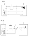
- FIG. 1 shows a method and a circuit arrangement for monitoring an electrical component 1 according to the prior art.
- the electrical component 1 is operated by means of a transformer-rectifier combination 3 with a DC voltage of 12 volts.
- the transformer-rectifier combination 3 is fed by means of the supply lines 4 with an AC voltage of 230 volts.
- the electrical component 1 comprises an error reporting device 2, which switches the switch S, depending on the operation of the electrical component 1 (proper operation 10 or fault 11 or malfunction), from the fault signaling device 2 into a closed or open position.
- the position of the switch S, which at the location of the electrical component 1 or at a central interlocking system 9 means is therefore an indicator for evaluating the operation of the electrical component 1.
- a special cabling 5 is required to check the operation of the electrical component 1 to the central signal box 9, a special cabling 5 is required. If the special cabling 5 is undesirable, the operation of the electrical component 1 can only be checked at the location of the electrical component 1.
- FIG. 2 shows a method according to the invention and a circuit arrangement according to the invention for monitoring an electrical component 1.
- the electrical component 1 is operated by means of a switching power supply 6 with a DC voltage of 12 volts.
- the switching power supply 6 is fed by means of the supply lines 4 with an AC voltage of 230 volts.
- the electrical component 1 comprises an error reporting device 2, which switches the switch S, depending on the operation of the electrical component 1 (proper operation 10 or fault 11 or malfunction), from the fault signaling device 2 into a closed or open position. The position of the switch S is therefore an indicator for evaluating the operation of the electrical component. 1
- the rectifier element 7 is in this case ineffective and therefore has no influence on the current shape of the current flowing in the supply lines 4 electrical current I (t) .
- the function of the rectifier element 7 is detected by a arranged in the supply line 4 detection device 8. This is done by the function of the rectifier element 7 is activated in case of error 11 by opening the switch S.
- the rectifier element 7 causes, depending on the polarity, the suppression of positive or negative current half-waves, with an associated change of the current shape in the supply lines 4.
- the change of the current shape is detected by the arranged in the supply line detection device 8.
- the detection device 8 is arranged in a central signal conditioning system 9.
- FIG. 3 shows the time course of the current I (t) during proper operation 10 of an electrical component 1 and 11 in case of failure or failure of an electrical component.
- the current I (t) has positive and negative half waves.
- the current I (t) only negative half-waves.
- the method according to the invention has the advantage that in the case of an error 11 or a malfunction of the electrical component, an error signal is transmitted exclusively by means of the supply lines 4. There is no additional special cabling 5 necessary. Another advantage results from the simple retrofitting of existing systems with electrical components 1. For this purpose, only one existing transformer-rectifier combination 3 is exchanged for a switching power supply 6 and a rectifier element 7 and a detection device 8 installed in one of the supply lines 4.
Landscapes
- Engineering & Computer Science (AREA)
- Mechanical Engineering (AREA)
- Automation & Control Theory (AREA)
- Power Engineering (AREA)
- Rectifiers (AREA)
- Testing Electric Properties And Detecting Electric Faults (AREA)
- Remote Monitoring And Control Of Power-Distribution Networks (AREA)
Abstract
Description
- Die Erfindung betrifft ein Verfahren zur Überwachung einer elektrischen Komponente, wobei die elektrische Komponente eine Fehlermeldeeinrichtung umfasst, und mittels eines über Speiseleitungen gespeisten Schaltnetzteils betrieben wird.
- Weiter umfasst die Erfindung eine Schaltungsanordnung zur Durchführung des erfindungsgemäßen Verfahrens.
- Elektrische Komponenten, insbesondere wenn es sich dabei um sicherheitsrelevante elektrische Komponenten wie beispielsweise optische Signalanlagen im Schienen- oder Straßenverkehr handelt, müssen ständig oder zumindest zyklisch auf ihren ordnungsgemäßen Betrieb geprüft werden. Solche elektrische Komponenten sind oftmals dezentral innerhalb eines weit verzweigten Netzwerkes angeordnet und werden mittels einer Transformator-Gleichrichter-Kombination mit Gleichspannung betrieben. Zwischen den elektrischen Komponenten befinden sich oftmals große räumliche Abstände. Es besteht die Möglichkeit, solche Komponenten vor Ort manuell auf ihren ordnungsgemäßen Betrieb zu prüfen, und im Fehlerfall oder auch präventiv auszutauschen. Dies ist auf Grund des dazu notwendigen Betriebspersonals aufwändig, teuer und ineffizient. Eine aus dem Stand der Technik bekannte Lösung dieses Problems besteht darin, die elektrischen Komponenten an einer zentralen Stelle auf ihren ordnungsgemäßen Betrieb zu prüfen beziehungsweise ständig zu überwachen. Dazu ist jedoch für jede elektrische Komponente zusätzlich zu den Versorgungsleitungen für die elektrische Komponente eine Sonderverkabelung zur Übertragung eines Fehlersignals oder Störsignals in die zentrale Stelle notwendig. Dazu ist bei bereits bestehenden Anlagen mit elektrischen Komponenten eine Nachverkabelung, bei Neuanlagen eine Sonderverkabelung erforderlich. Beides ist aufwändig und teuer.
- Der Erfindung liegt die Aufgabe zugrunde, ein Verfahren und eine Schaltungsanordnung zur Überwachung einer elektrischen Komponente anzugeben, bei der im Fehlerfall oder Störfall der elektrischen Komponente ein Fehlersignal mittels der Versorgungsleitungen der elektrischen Komponente in eine zentrale Stelle übertragen wird.
- Die Aufgabe wird durch ein Verfahren zur Überwachung einer elektrischen Komponente gelöst, wobei die elektrische Komponente eine Fehlermeldeeinrichtung umfasst und mittels eines über Versorgungsleitungen gespeisten Schaltnetzteils betrieben wird, und wobei erfindungsgemäß ein in einer der Versorgungsleitungen angeordnetes Gleichrichterelement während des ordnungsgemäßen Betriebes der elektrischen Komponente mittels eines von der Fehlermeldeeinrichtung betätigten Schalters überbrückt wird und wobei im Fehlerfall oder Störfall die Funktion des Gleichrichtelementes durch eine in der Versorgungsleitung angeordnete Detektionseinrichtung erkannt wird.
- Bei ordnungsgemäßem Betrieb der elektrischen Komponente wird das Gleichrichterelement vom Schalter elektrisch überbrückt. Das Gleichrichterelement in diesem Fall wirkungslos und hat daher auch keinen Einfluss auf die Stromform des in den Versorgungsleitungen fließenden elektrischen Stroms.
- Im Fehlerfall oder Störfall der elektrischen Komponente wird der Schalter von der Fehlermeldeeinrichtung geöffnet wodurch die Funktion des Gleichrichterelements aktiviert wird. In diesem Fall bewirkt das Gleichrichterelement, abhängig von der Polung, die Unterdrückung von positiven beziehungsweise negativen Stromhalbwellen, mit einer damit verbundenen Änderung der Stromform in den Versorgungsleitungen. Die Änderung der Stromform wird von der in der Versorgungsleitung angeordneten Detektionseinrichtung erkannt.
- Im Fehlerfall oder Störfall stehen nur mehr positive oder nur mehr negative Stromhalbwellen zur Speisung des Schaltnetzteils zur Verfügung. Ist das Schaltnetzteil entsprechend überdimensioniert, so führt dies zu keiner Beeinträchtigung des Betriebs der elektrischen Komponente.
- Das erfindungsgemäße Verfahren hat den Vorteil, dass im Fehlerfall oder Störfall der elektrischen Komponente ein Fehlersignal ausschließlich mittels der Versorgungsleitungen übertragen wird. Es ist dazu keine zusätzliche Sonderverkabelung notwendig. Ein weiterer Vorteil ergibt sich durch die einfache Nachrüstbarkeit bereits bestehender Anlagen mit elektrischen Komponenten. Dazu wird lediglich eine vorhanden Transformator-Gleichrichter-Kombination gegen ein Schaltnetzteil ausgetauscht und ein Gleichrichterelement sowie eine Detektionseinrichtung in eine der Versorgungsleitungen eingebaut.
- Damit können elektrische Komponenten, auch wenn diese dezentral in großen räumlichen Abständen zueinander angeordnet sind, an einer zentralen Stelle auf ihren ordnungsgemäßen Betrieb geprüft beziehungsweise überwacht werden.
- Vorzugsweise ist die elektrische Komponente eine Signaleinrichtung innerhalb eines Eisenbahnnetzes, welche überwacht wird. Eine Signaleinrichtung ist beispielsweise eine Doppelfadenüberwachungseinrichtung, ein Isolationsprüfgerät für Lichtsignalstromkreise, ein elektronisches Weichenendlagenprüfsystem, eine dezentralisierte Hilfsstromversorgung oder auch eine Batterieüberwachung für solche Signaleinrichtungen.
- Erfindungsgemäß werden solche Signaleinrichtungen auf ihren odnungsgemäßen Betrieb überwacht. Da es sich bei den Signaleinrichtungen meistens um Einrichtungen zur Reduzierung des Gefahrenpotentials für Personen und Sachen handelt, ist die erfindungsgemäße permanente Überwachung besonders wichtig.
- Vorzugsweise ist als Gleichrichterelement eine Diode vorgesehen.
- Die Detektionseinrichtung ist bevorzugt in einer zentralen Stellwerkanlage angeordnet. Dort erfolgt eine Auswertung der Stromhalbwellen in der Versorgungsleitung.
- Der ordnungsgemäße Betrieb einer dezentral angeordneten elektrischen Komponente kann dadurch an einer zentralen Stelle überprüft werden, ohne zusätzliche Sonderverkabelung oder Nachverkabelung.
- Die vom Schaltnetzteil erzeugte Ausgangsspannung, mittels der die elektrische Komponente betrieben wird, wird geregelt.
- Damit können unterschiedliche elektrische Komponenten mit unterschiedlicher Leistungs- beziehungsweise Stromaufnahme mit dem Schaltnetzteil betrieben werden.
- Das Schaltnetzteil wird mit einer Wechselspannung zwischen 100 Volt und 265 Volt gespeist.
- Ein weiterer Gegenstand der Erfindung ist eine Schaltungsanordnung zur Durchführung des erfindungsgemäßen Verfahrens, wobei die Schaltungsanordnung umfasst:
- eine zu überwachende elektrische Komponente mit einer Fehlermeldeeinrichtung,
- ein Schaltnetzteil zum Betreiben der elektrischen Komponente mit in das Schaltnetzteil mündenden Versorgungsleitungen zum Einbringen von elektrischer Energie in das Schaltnetzteil,
- ein in einer der Versorgungsleitungen angeordnetes Gleichrichterelement, welches während des ordnungsgemäßen Betriebes der elektrischen Komponente mittels eines von der Fehlermeldeeinrichtung betätigten Schalters überbrückt wird,
- eine in der Versorgungsleitung angeordnete Detektionseinrichtung, zur Erkennung der Funktion des Gleichrichtelementes im Fehlerfall der elektrischen Komponente.
- Damit können elektrische Komponenten, auch wenn diese dezentral in großen räumlichen Abständen zueinander angeordnet sind, an einer zentralen Stelle auf ihren ordnungsgemäßen Betrieb geprüft beziehungsweise überwacht werden.
- In einer bevorzugten Ausführungsform der ist die elektrische Komponente eine Signaleinrichtung innerhalb eines Eisenbahnnetzes.
- Als Gleichrichterelement ist vorzugsweise eine Diode vorgesehen.
- Die Detektionseinrichtung ist in einer weiteren bevorzugten Ausführungsform in einer zentralen Stellwerkanlage eines Eisenbahnnetzes angeordnet.
- Der ordnungsgemäße Betrieb einer dezentral angeordneten elektrischen Komponente kann dadurch an einer zentralen Stelle überprüft werden, ohne zusätzliche Sonderverkabelung oder Nachverkabelung.
- Wenn das Schaltnetzteil über eine regelbare Ausgangsspannung verfügt, können damit unterschiedliche elektrische Komponenten mit unterschiedlicher Leistungs- beziehungsweise Stromaufnahme mit dem Schaltnetzteil betrieben werden.
- Das Schaltnetzteil ist für den Betrieb mit einer Wechselspannung zwischen 100 Volt und 265 Volt ausgelegt.
- Es zeigen beispielhaft und schematisch
-
FIG 1 ein Verfahren und eine Schaltungsanordnung zur Überwachung einer elektrischen Komponente 1 nach dem Stand der Technik. -
FIG 2 ein erfindungsgemäßes Verfahren und eine erfindungsgemäße Schaltungsanordnung zur Überwachung einer elektrischen Komponente 1. -
FIG 3 die Stromform bei ordnungsgemäßen Betrieb 10 einer elektrischen Komponente 1 und im Fehlerfall 11 oder Störfall einer elektrischen Komponente 1. -
FIG 1 zeigt ein Verfahren und eine Schaltungsanordnung zur Überwachung einer elektrischen Komponente 1 nach dem Stand der Technik. Die elektrische Komponente 1 wird mittels einer Transformator-Gleichrichterkombination 3 mit einer Gleichspannung von 12 Volt betrieben. Die Transformator-Gleichrichterkombination 3 wird mittels der Versorgungsleitungen 4 mit einer Wechselspannung von 230 Volt gespeist. Die elektrische Komponente 1 umfasst eine Fehlermeldeeinrichtung 2, welche den Schalter S, je nach Betrieb der elektrischen Komponente 1 (ordnungsgemäßer Betrieb 10 oder Fehlerfall 11 beziehungsweise Störfall) von der Fehlermeldeeinrichtung 2 in eine Geschlossen oder Offen - Stellung gebracht wird. Die Stellung des Schalters S, welche am Ort der elektrischen Komponente 1 oder an einer zentralen Stellwerkanlage 9 mittels geeigneter Einrichtungen überprüft beziehungsweise überwacht wird, ist daher ein Indikator zur Bewertung des Betriebs der elektrischen Komponente 1. Zur Überprüfung des Betriebs der elektrischen Komponente 1 an der zentralen Stellwerkanlage 9 ist jedoch eine Sonderverkabelung 5 erforderlich. Ist die Sonderverkabelung 5 unerwünscht, kann der Betrieb der elektrischen Komponente 1 nur am Ort der elektrischen Komponente 1 überprüft werden. -
FIG 2 zeigt ein erfindungsgemäßes Verfahren und eine erfindungsgemäße Schaltungsanordnung zur Überwachung einer elektrischen Komponente 1. - Die elektrische Komponente 1 wird mittels eines Schaltnetzteils 6 mit einer Gleichspannung von 12 Volt betrieben. Das Schaltnetzteil 6 wird mittels der Versorgungsleitungen 4 mit einer Wechselspannung von 230 Volt gespeist. Die elektrische Komponente 1 umfasst eine Fehlermeldeeinrichtung 2, welche den Schalter S, je nach Betrieb der elektrischen Komponente 1 (ordnungsgemäßer Betrieb 10 oder Fehlerfall 11 beziehungsweise Störfall) von der Fehlermeldeeinrichtung 2 in eine Geschlossen oder Offen - Stellung gebracht wird. Die Stellung des Schalters S ist daher ein Indikator zur Bewertung des Betriebs der elektrischen Komponente 1.
- Während des ordnungsgemäßen Betriebs 10 der elektrischen Komponente 1, wird, wie in
FIG 2 dargestellt, ein in einer Versorgungsleitung 4 angeordnetes Gleichrichterelement 7 mittels des von der Fehlermeldeeinrichtung 2 betätigten Schalters S überbrückt. Das Gleichrichterelement 7 ist in diesem Fall wirkungslos und hat daher auch keinen Einfluss auf die Stromform des in den Versorgungsleitungen 4 fließenden elektrischen Stroms I(t). - Im Fehlerfall 11 oder Störfall der elektrischen Komponente 1 wird die Funktion des Gleichrichterelements 7 durch eine in der Versorgungsleitung 4 angeordnete Detektionseinrichtung 8 erkannt. Dies erfolgt dadurch, dass die Funktion des Gleichrichterelements 7 im Fehlerfall 11 durch Öffnen des Schalters S aktiviert wird. In diesem Fall bewirkt das Gleichrichterelement 7, abhängig von der Polung, die Unterdrückung von positiven beziehungsweise negativen Stromhalbwellen, mit einer damit verbundenen Änderung der Stromform in den Versorgungsleitungen 4. Die Änderung der Stromform wird von der in der Versorgungsleitung angeordneten Detektionseinrichtung 8 erkannt. Die Detektionseinrichtung 8 ist in einer zentralen Stellwerkanlage 9 angeordnet.
-
FIG 3 zeigt den zeitlichen Verlauf des Stroms I(t) bei ordnungsgemäßen Betrieb 10 einer elektrischen Komponente 1 und im Fehlerfall 11 oder Störfall einer elektrischen Komponente 1. - Während des ordnungsgemäßen Betriebs 10 der elektrischen Komponente 1 weist der Strom I(t) positive und negative Halbwellen auf. Im Fehlerfall 11 oder Störfall der elektrischen Komponente 1 weist der Strom I(t) nur negative Halbwellen auf.
- Das erfindungsgemäße Verfahren hat den Vorteil, dass im Fehlerfall 11 oder Störfall der elektrischen Komponente ein Fehlersignal ausschließlich mittels der Versorgungsleitungen 4 übertragen wird. Es ist dazu keine zusätzliche Sonderverkabelung 5 notwendig. Ein weiterer Vorteil ergibt sich durch die einfache Nachrüstbarkeit bereits bestehender Anlagen mit elektrischen Komponenten 1. Dazu wird lediglich eine vorhanden Transformator-Gleichrichter-Kombination 3 gegen ein Schaltnetzteil 6 ausgetauscht und ein Gleichrichterelement 7 sowie eine Detektionseinrichtung 8 in eine der Versorgungsleitungen 4 eingebaut.
- Damit können elektrische Komponenten 1, auch wenn diese dezentral in großen räumlichen Abständen zueinander angeordnet sind, an einer zentralen Stelle auf ihren ordnungsgemäßen Betrieb geprüft beziehungsweise überwacht werden.
- Die erfindungsgemäße Lösung ist nicht auf die dargestellten Beispiele beschränkt, es sind auch andere Ausführungen denkbar.
-
- 1
- elektrische Komponente
- 2
- Fehlermeldeeinrichtung
- 3
- Transformator-Gleichrichter-Kombination
- 4
- Versorgungsleitung
- 5
- Sonderverkabelung
- 6
- Schaltnetzteil
- 7
- Gleichrichterelement
- 8
- Detektionseinrichtung
- 9
- zentrale Stellwerkanlage
- 10
- ordnungsgemäßer Betrieb
- 11
- Fehlerfall
- S
- Schalter
- t
- Zeit
- I(t)
- Strom
Claims (12)
- Verfahren zur Überwachung einer elektrischen Komponente (1), wobei die elektrische Komponente (1) eine Fehlermeldeeinrichtung (2) umfasst und mittels eines über Versorgungsleitungen (4) gespeisten Schaltnetzteils (6) betrieben wird, dadurch gekennzeichnet, dass ein in einer der Versorgungsleitungen (4) angeordnetes Gleichrichterelement (7) während des ordnungsgemäßen Betriebes der elektrischen Komponente (1) mittels eines von der Fehlermeldeeinrichtung (2) betätigten Schalters S überbrückt wird, und dass im Fehlerfall oder Störfall die Funktion des Gleichrichtelementes (7) durch eine in der Versorgungsleitung (4) angeordnete Detektionseinrichtung (8) erkannt wird.
- Verfahren nach Anspruch 1, dadurch gekennzeichnet, dass die elektrische Komponente (1) eine Signaleinrichtung innerhalb eines Eisenbahnnetzes ist und überwacht wird.
- Verfahren nach einem der Ansprüche 1 oder 2, dadurch gekennzeichnet, dass als Gleichrichterelement (7) eine Diode vorgesehen ist.
- Verfahren nach einem der Ansprüche 1 bis 3, dadurch gekennzeichnet, dass mittels der Detektionseinrichtung (8), welche in einer zentralen Stellwerkanlage (9) angeordnet ist, eine Auswertung von Stromhalbwellen in der Versorgungsleitung erfolgt.
- Verfahren nach einem der Ansprüche 1 bis 4, dadurch gekennzeichnet, dass eine vom Schaltnetzteil (6) erzeugte Ausgangsspannung, mittels der die elektrische Komponente (1) betrieben wird, geregelt wird.
- Verfahren nach einem der Ansprüche 1 bis 5, dadurch gekennzeichnet, dass das Schaltnetzteil (6) mit einer Wechselspannung zwischen 100 Volt und 265 Volt gespeist wird.
- Schaltungsanordnung zur Durchführung des Verfahrens nach einem der Ansprüche 1 bis 6, umfassend:- eine zu überwachende elektrische Komponente (1) mit einer Fehlermeldeeinrichtung (2),- ein Schaltnetzteil (6) zum Betreiben der elektrischen Komponente (1) mit in das Schaltnetzteil (6) mündenden Versorgungsleitungen (4) zum Einbringen von elektrischer Energie in das Schaltnetzteil (6),dadurch gekennzeichnet, dass die Schaltungsanordnung weiter umfasst:- ein in einer der Versorgungsleitungen (4) angeordnetes Gleichrichterelement (7), welches während des ordnungsgemäßen Betriebes der elektrischen Komponente (1) mittels eines von der Fehlermeldeeinrichtung (2) betätigten Schalters überbrückt wird,- eine in der Versorgungsleitung (4) angeordnete Detektionseinrichtung (8), zur Erkennung der Funktion des Gleichrichtelementes (7) im Fehlerfall der elektrischen Komponente (1).
- Schaltungsanordnung nach Anspruch 7, dadurch gekennzeichnet, dass die elektrische Komponente (1) eine Signaleinrichtung innerhalb eines Eisenbahnnetzes ist.
- Schaltungsanordnung nach einem der Ansprüche 7 oder 8, dadurch gekennzeichnet, dass als Gleichrichterelement (7) eine Diode vorgesehen ist.
- Schaltungsanordnung nach einem der Ansprüche 7 bis 9, dadurch gekennzeichnet, dass die Detektionseinrichtung (8) in einer zentralen Stellwerkanlage (9) eines Eisenbahnnetzes angeordnet ist.
- Schaltungsanordnung nach einem der Ansprüche 7 bis 10, dadurch gekennzeichnet, dass das Schaltnetzteil (6) über eine regelbare Ausgangsspannung verfügt.
- Schaltungsanordnung nach einem der Ansprüche 7 bis 11, dadurch gekennzeichnet, dass das Schaltnetzteil (6) für den Betrieb mit einer Wechselspannung zwischen 100 Volt und 265 Volt ausgelegt ist.
Applications Claiming Priority (1)
| Application Number | Priority Date | Filing Date | Title |
|---|---|---|---|
| ATA50039/2013A AT513940B1 (de) | 2013-01-22 | 2013-01-22 | Überwachung einer elektrischen Komponente |
Publications (3)
| Publication Number | Publication Date |
|---|---|
| EP2757018A2 true EP2757018A2 (de) | 2014-07-23 |
| EP2757018A3 EP2757018A3 (de) | 2017-12-27 |
| EP2757018B1 EP2757018B1 (de) | 2019-04-24 |
Family
ID=49999743
Family Applications (1)
| Application Number | Title | Priority Date | Filing Date |
|---|---|---|---|
| EP14151453.9A Active EP2757018B1 (de) | 2013-01-22 | 2014-01-16 | Überwachung einer elektrischen Komponente |
Country Status (2)
| Country | Link |
|---|---|
| EP (1) | EP2757018B1 (de) |
| AT (1) | AT513940B1 (de) |
Family Cites Families (9)
| Publication number | Priority date | Publication date | Assignee | Title |
|---|---|---|---|---|
| GB8328926D0 (en) * | 1983-10-29 | 1983-11-30 | Ml Eng Plymouth | Electrical power supply unit |
| JPH01212933A (ja) * | 1988-02-19 | 1989-08-25 | Fujitsu Ltd | 障害検出方法 |
| EP0678078B1 (de) * | 1993-11-05 | 1998-09-02 | Siemens Schweiz AG | Schaltungsanordnung für eisenbahn-lichtsignalanlagen |
| DE59601254D1 (de) * | 1995-09-18 | 1999-03-18 | Siemens Ag | Kommunikationssystem |
| GB2408834B (en) * | 2001-12-11 | 2005-07-20 | Westinghouse Brake & Signal | Signal lamps and apparatus |
| US20060259202A1 (en) * | 2005-01-24 | 2006-11-16 | Vaish Himangshu R | Signaling system |
| JP4046744B2 (ja) * | 2005-09-22 | 2008-02-13 | 大同信号株式会社 | 切替素子故障検出回路 |
| JP5017179B2 (ja) * | 2008-05-28 | 2012-09-05 | 株式会社日立製作所 | 故障検知機能付デジタル出力回路 |
| CN201626433U (zh) * | 2009-11-20 | 2010-11-10 | 北京国铁路阳技术有限公司 | 铁路系统用的带有一套备用电路的高可靠供电系统 |
-
2013
- 2013-01-22 AT ATA50039/2013A patent/AT513940B1/de not_active IP Right Cessation
-
2014
- 2014-01-16 EP EP14151453.9A patent/EP2757018B1/de active Active
Non-Patent Citations (1)
| Title |
|---|
| None |
Also Published As
| Publication number | Publication date |
|---|---|
| AT513940A1 (de) | 2014-08-15 |
| AT513940B1 (de) | 2015-01-15 |
| EP2757018B1 (de) | 2019-04-24 |
| EP2757018A3 (de) | 2017-12-27 |
Similar Documents
| Publication | Publication Date | Title |
|---|---|---|
| EP3699015B1 (de) | Elektrische schaltungsvorrichtung zur erkennung eines nichtgeöffneten schaltkontaktes sowie einer schutzleiterunterbrechung in einer ein- oder mehrphasigen elektrischen zuleitung | |
| DE102009040692B4 (de) | Leistungsschalter | |
| EP1665483B1 (de) | Einrichtung zur überwachung des leckstroms eines überspannungsableiters | |
| EP2907208A2 (de) | Differenzstrom-überwachungseinrichtung mit lichtbogenerkennung | |
| EP3273459A1 (de) | Einrichtung und verfahren zur überwachung einer unterbrechungseinheit in einem elektrischen energieversorgungsnetz sowie verteilerstation mit einer überwachten unterbrechungseinheit | |
| DE102010056006B4 (de) | Verfahren zur Überwachung eines Leitungsnetzes für ein Fahrzeug sowie entsprechende Überwachungsvorrichtung und Fahrzeug | |
| DE102017007252B3 (de) | Überwachungsvorrichtung und Verfahren zur kontinuierlichen und vom Bahnrückstromfluss unabhängigen Überwachung der Integrität der Rückleitungsanschlussleiter einer Rückleitung für den Bahnstrom einer Bahnenergieversorungsanlage und Rückleitungs-System mit einer Rückleitung und einer Überwachungsvorrichtung zur Überwachung der Integrität der Rückleitungsanschlussleiter der Rückleitung | |
| EP2672622A1 (de) | Frequenzumrichter mit Bremswiderstand und Verfahren zur Funktionsüberwachung eines Bremswiderstandes in einem Frequenzumrichterbetrieb | |
| EP2757018B1 (de) | Überwachung einer elektrischen Komponente | |
| DE102016216321A1 (de) | Schaltvorrichtung und Verfahren zum Schalten eines Stromes | |
| EP1340988A2 (de) | Verfahren und Vorrichtung zur Messung der Impedanz eines elektrischen Energieversorgungsnetzes | |
| DE3048683C2 (de) | ||
| DE1605427A1 (de) | Schaltungsanordnung zum Erzeugen und UEbertragen von Achszaehlimpulsen in Achszaehlanlagen | |
| EP2907149B1 (de) | System zur funktionsüberwachung einer stromschleife | |
| DE19606894C2 (de) | Einrichtung zur signaltechnisch sicheren Steuerung und Überwachung elektrischer Verbraucher im Eisenbahnwesen | |
| DE102012111615A1 (de) | Fehlerstromschutzschalter | |
| DE4203299A1 (de) | Schaltungsanordnung zur isolationsueberwachung von spannungszwischenkreisen | |
| EP4184180B1 (de) | Vorrichtung und verfahren zum schutz einer person vor einem elektrischen signal | |
| EP2055982B1 (de) | Einrichtung zur Detektion eines maximal zulässigen Verschleißzustands von Bremsbelägen in Reibungsbremsen eines Schienenfahrzeugs | |
| DE19823441C1 (de) | Digitaleingabebaugruppe | |
| EP3131192B1 (de) | Steuervorrichtung und verfahren zur steuerung einer sicherheitsrelevanten komponente | |
| DE102012220692A1 (de) | Verfahren und Vorrichtung zur Überwachung eines Prüfintervalls für eine Fehlerstrom-Schutzeinrichtung | |
| DE102005030085B4 (de) | Vorrichtung und Verfahren zur Prüfung und/oder Überwachung einer elektromagnetisch betätigbaren Bremse sowie Elektromotor mit Vorrichtung | |
| EP2773001A1 (de) | Einrichtung für elektrische Sicherheit und Verfahren für ein fahrerloses Schienentransportmittel | |
| DE4325732C2 (de) | Verfahren zur potentialfreien Überwachung von Ringleitungen |
Legal Events
| Date | Code | Title | Description |
|---|---|---|---|
| PUAI | Public reference made under article 153(3) epc to a published international application that has entered the european phase |
Free format text: ORIGINAL CODE: 0009012 |
|
| 17P | Request for examination filed |
Effective date: 20140116 |
|
| AK | Designated contracting states |
Kind code of ref document: A2 Designated state(s): AL AT BE BG CH CY CZ DE DK EE ES FI FR GB GR HR HU IE IS IT LI LT LU LV MC MK MT NL NO PL PT RO RS SE SI SK SM TR |
|
| AX | Request for extension of the european patent |
Extension state: BA ME |
|
| PUAL | Search report despatched |
Free format text: ORIGINAL CODE: 0009013 |
|
| AK | Designated contracting states |
Kind code of ref document: A3 Designated state(s): AL AT BE BG CH CY CZ DE DK EE ES FI FR GB GR HR HU IE IS IT LI LT LU LV MC MK MT NL NO PL PT RO RS SE SI SK SM TR |
|
| AX | Request for extension of the european patent |
Extension state: BA ME |
|
| RIC1 | Information provided on ipc code assigned before grant |
Ipc: B61L 1/20 20060101ALI20171120BHEP Ipc: B61L 5/18 20060101AFI20171120BHEP |
|
| STAA | Information on the status of an ep patent application or granted ep patent |
Free format text: STATUS: REQUEST FOR EXAMINATION WAS MADE |
|
| R17P | Request for examination filed (corrected) |
Effective date: 20180625 |
|
| RBV | Designated contracting states (corrected) |
Designated state(s): AL AT BE BG CH CY CZ DE DK EE ES FI FR GB GR HR HU IE IS IT LI LT LU LV MC MK MT NL NO PL PT RO RS SE SI SK SM TR |
|
| GRAP | Despatch of communication of intention to grant a patent |
Free format text: ORIGINAL CODE: EPIDOSNIGR1 |
|
| STAA | Information on the status of an ep patent application or granted ep patent |
Free format text: STATUS: GRANT OF PATENT IS INTENDED |
|
| INTG | Intention to grant announced |
Effective date: 20181122 |
|
| GRAS | Grant fee paid |
Free format text: ORIGINAL CODE: EPIDOSNIGR3 |
|
| GRAA | (expected) grant |
Free format text: ORIGINAL CODE: 0009210 |
|
| STAA | Information on the status of an ep patent application or granted ep patent |
Free format text: STATUS: THE PATENT HAS BEEN GRANTED |
|
| AK | Designated contracting states |
Kind code of ref document: B1 Designated state(s): AL AT BE BG CH CY CZ DE DK EE ES FI FR GB GR HR HU IE IS IT LI LT LU LV MC MK MT NL NO PL PT RO RS SE SI SK SM TR |
|
| REG | Reference to a national code |
Ref country code: GB Ref legal event code: FG4D Free format text: NOT ENGLISH |
|
| REG | Reference to a national code |
Ref country code: CH Ref legal event code: EP |
|
| REG | Reference to a national code |
Ref country code: AT Ref legal event code: REF Ref document number: 1123790 Country of ref document: AT Kind code of ref document: T Effective date: 20190515 Ref country code: IE Ref legal event code: FG4D Free format text: LANGUAGE OF EP DOCUMENT: GERMAN |
|
| REG | Reference to a national code |
Ref country code: DE Ref legal event code: R096 Ref document number: 502014011490 Country of ref document: DE |
|
| RAP2 | Party data changed (patent owner data changed or rights of a patent transferred) |
Owner name: SIEMENS MOBILITY GMBH |
|
| REG | Reference to a national code |
Ref country code: NL Ref legal event code: MP Effective date: 20190424 |
|
| REG | Reference to a national code |
Ref country code: LT Ref legal event code: MG4D |
|
| PG25 | Lapsed in a contracting state [announced via postgrant information from national office to epo] |
Ref country code: NL Free format text: LAPSE BECAUSE OF FAILURE TO SUBMIT A TRANSLATION OF THE DESCRIPTION OR TO PAY THE FEE WITHIN THE PRESCRIBED TIME-LIMIT Effective date: 20190424 |
|
| PG25 | Lapsed in a contracting state [announced via postgrant information from national office to epo] |
Ref country code: LT Free format text: LAPSE BECAUSE OF FAILURE TO SUBMIT A TRANSLATION OF THE DESCRIPTION OR TO PAY THE FEE WITHIN THE PRESCRIBED TIME-LIMIT Effective date: 20190424 Ref country code: ES Free format text: LAPSE BECAUSE OF FAILURE TO SUBMIT A TRANSLATION OF THE DESCRIPTION OR TO PAY THE FEE WITHIN THE PRESCRIBED TIME-LIMIT Effective date: 20190424 Ref country code: HR Free format text: LAPSE BECAUSE OF FAILURE TO SUBMIT A TRANSLATION OF THE DESCRIPTION OR TO PAY THE FEE WITHIN THE PRESCRIBED TIME-LIMIT Effective date: 20190424 Ref country code: SE Free format text: LAPSE BECAUSE OF FAILURE TO SUBMIT A TRANSLATION OF THE DESCRIPTION OR TO PAY THE FEE WITHIN THE PRESCRIBED TIME-LIMIT Effective date: 20190424 Ref country code: PT Free format text: LAPSE BECAUSE OF FAILURE TO SUBMIT A TRANSLATION OF THE DESCRIPTION OR TO PAY THE FEE WITHIN THE PRESCRIBED TIME-LIMIT Effective date: 20190824 Ref country code: NO Free format text: LAPSE BECAUSE OF FAILURE TO SUBMIT A TRANSLATION OF THE DESCRIPTION OR TO PAY THE FEE WITHIN THE PRESCRIBED TIME-LIMIT Effective date: 20190724 Ref country code: AL Free format text: LAPSE BECAUSE OF FAILURE TO SUBMIT A TRANSLATION OF THE DESCRIPTION OR TO PAY THE FEE WITHIN THE PRESCRIBED TIME-LIMIT Effective date: 20190424 Ref country code: FI Free format text: LAPSE BECAUSE OF FAILURE TO SUBMIT A TRANSLATION OF THE DESCRIPTION OR TO PAY THE FEE WITHIN THE PRESCRIBED TIME-LIMIT Effective date: 20190424 |
|
| PG25 | Lapsed in a contracting state [announced via postgrant information from national office to epo] |
Ref country code: RS Free format text: LAPSE BECAUSE OF FAILURE TO SUBMIT A TRANSLATION OF THE DESCRIPTION OR TO PAY THE FEE WITHIN THE PRESCRIBED TIME-LIMIT Effective date: 20190424 Ref country code: PL Free format text: LAPSE BECAUSE OF FAILURE TO SUBMIT A TRANSLATION OF THE DESCRIPTION OR TO PAY THE FEE WITHIN THE PRESCRIBED TIME-LIMIT Effective date: 20190424 Ref country code: LV Free format text: LAPSE BECAUSE OF FAILURE TO SUBMIT A TRANSLATION OF THE DESCRIPTION OR TO PAY THE FEE WITHIN THE PRESCRIBED TIME-LIMIT Effective date: 20190424 Ref country code: GR Free format text: LAPSE BECAUSE OF FAILURE TO SUBMIT A TRANSLATION OF THE DESCRIPTION OR TO PAY THE FEE WITHIN THE PRESCRIBED TIME-LIMIT Effective date: 20190725 Ref country code: BG Free format text: LAPSE BECAUSE OF FAILURE TO SUBMIT A TRANSLATION OF THE DESCRIPTION OR TO PAY THE FEE WITHIN THE PRESCRIBED TIME-LIMIT Effective date: 20190724 |
|
| PG25 | Lapsed in a contracting state [announced via postgrant information from national office to epo] |
Ref country code: IS Free format text: LAPSE BECAUSE OF FAILURE TO SUBMIT A TRANSLATION OF THE DESCRIPTION OR TO PAY THE FEE WITHIN THE PRESCRIBED TIME-LIMIT Effective date: 20190824 |
|
| REG | Reference to a national code |
Ref country code: DE Ref legal event code: R097 Ref document number: 502014011490 Country of ref document: DE |
|
| PG25 | Lapsed in a contracting state [announced via postgrant information from national office to epo] |
Ref country code: RO Free format text: LAPSE BECAUSE OF FAILURE TO SUBMIT A TRANSLATION OF THE DESCRIPTION OR TO PAY THE FEE WITHIN THE PRESCRIBED TIME-LIMIT Effective date: 20190424 Ref country code: CZ Free format text: LAPSE BECAUSE OF FAILURE TO SUBMIT A TRANSLATION OF THE DESCRIPTION OR TO PAY THE FEE WITHIN THE PRESCRIBED TIME-LIMIT Effective date: 20190424 Ref country code: SK Free format text: LAPSE BECAUSE OF FAILURE TO SUBMIT A TRANSLATION OF THE DESCRIPTION OR TO PAY THE FEE WITHIN THE PRESCRIBED TIME-LIMIT Effective date: 20190424 Ref country code: DK Free format text: LAPSE BECAUSE OF FAILURE TO SUBMIT A TRANSLATION OF THE DESCRIPTION OR TO PAY THE FEE WITHIN THE PRESCRIBED TIME-LIMIT Effective date: 20190424 Ref country code: EE Free format text: LAPSE BECAUSE OF FAILURE TO SUBMIT A TRANSLATION OF THE DESCRIPTION OR TO PAY THE FEE WITHIN THE PRESCRIBED TIME-LIMIT Effective date: 20190424 |
|
| PG25 | Lapsed in a contracting state [announced via postgrant information from national office to epo] |
Ref country code: IT Free format text: LAPSE BECAUSE OF FAILURE TO SUBMIT A TRANSLATION OF THE DESCRIPTION OR TO PAY THE FEE WITHIN THE PRESCRIBED TIME-LIMIT Effective date: 20190424 Ref country code: SM Free format text: LAPSE BECAUSE OF FAILURE TO SUBMIT A TRANSLATION OF THE DESCRIPTION OR TO PAY THE FEE WITHIN THE PRESCRIBED TIME-LIMIT Effective date: 20190424 |
|
| PLBE | No opposition filed within time limit |
Free format text: ORIGINAL CODE: 0009261 |
|
| STAA | Information on the status of an ep patent application or granted ep patent |
Free format text: STATUS: NO OPPOSITION FILED WITHIN TIME LIMIT |
|
| PG25 | Lapsed in a contracting state [announced via postgrant information from national office to epo] |
Ref country code: TR Free format text: LAPSE BECAUSE OF FAILURE TO SUBMIT A TRANSLATION OF THE DESCRIPTION OR TO PAY THE FEE WITHIN THE PRESCRIBED TIME-LIMIT Effective date: 20190424 |
|
| 26N | No opposition filed |
Effective date: 20200127 |
|
| PG25 | Lapsed in a contracting state [announced via postgrant information from national office to epo] |
Ref country code: SI Free format text: LAPSE BECAUSE OF FAILURE TO SUBMIT A TRANSLATION OF THE DESCRIPTION OR TO PAY THE FEE WITHIN THE PRESCRIBED TIME-LIMIT Effective date: 20190424 |
|
| REG | Reference to a national code |
Ref country code: DE Ref legal event code: R119 Ref document number: 502014011490 Country of ref document: DE |
|
| PG25 | Lapsed in a contracting state [announced via postgrant information from national office to epo] |
Ref country code: MC Free format text: LAPSE BECAUSE OF FAILURE TO SUBMIT A TRANSLATION OF THE DESCRIPTION OR TO PAY THE FEE WITHIN THE PRESCRIBED TIME-LIMIT Effective date: 20190424 |
|
| REG | Reference to a national code |
Ref country code: CH Ref legal event code: PL |
|
| GBPC | Gb: european patent ceased through non-payment of renewal fee |
Effective date: 20200116 |
|
| REG | Reference to a national code |
Ref country code: BE Ref legal event code: MM Effective date: 20200131 |
|
| PG25 | Lapsed in a contracting state [announced via postgrant information from national office to epo] |
Ref country code: GB Free format text: LAPSE BECAUSE OF NON-PAYMENT OF DUE FEES Effective date: 20200116 Ref country code: LU Free format text: LAPSE BECAUSE OF NON-PAYMENT OF DUE FEES Effective date: 20200116 Ref country code: DE Free format text: LAPSE BECAUSE OF NON-PAYMENT OF DUE FEES Effective date: 20200801 Ref country code: FR Free format text: LAPSE BECAUSE OF NON-PAYMENT OF DUE FEES Effective date: 20200131 |
|
| PG25 | Lapsed in a contracting state [announced via postgrant information from national office to epo] |
Ref country code: CH Free format text: LAPSE BECAUSE OF NON-PAYMENT OF DUE FEES Effective date: 20200131 Ref country code: LI Free format text: LAPSE BECAUSE OF NON-PAYMENT OF DUE FEES Effective date: 20200131 Ref country code: BE Free format text: LAPSE BECAUSE OF NON-PAYMENT OF DUE FEES Effective date: 20200131 |
|
| PG25 | Lapsed in a contracting state [announced via postgrant information from national office to epo] |
Ref country code: IE Free format text: LAPSE BECAUSE OF NON-PAYMENT OF DUE FEES Effective date: 20200116 |
|
| REG | Reference to a national code |
Ref country code: AT Ref legal event code: MM01 Ref document number: 1123790 Country of ref document: AT Kind code of ref document: T Effective date: 20200116 |
|
| PG25 | Lapsed in a contracting state [announced via postgrant information from national office to epo] |
Ref country code: AT Free format text: LAPSE BECAUSE OF NON-PAYMENT OF DUE FEES Effective date: 20200116 |
|
| PG25 | Lapsed in a contracting state [announced via postgrant information from national office to epo] |
Ref country code: MT Free format text: LAPSE BECAUSE OF FAILURE TO SUBMIT A TRANSLATION OF THE DESCRIPTION OR TO PAY THE FEE WITHIN THE PRESCRIBED TIME-LIMIT Effective date: 20190424 Ref country code: CY Free format text: LAPSE BECAUSE OF FAILURE TO SUBMIT A TRANSLATION OF THE DESCRIPTION OR TO PAY THE FEE WITHIN THE PRESCRIBED TIME-LIMIT Effective date: 20190424 |
|
| PG25 | Lapsed in a contracting state [announced via postgrant information from national office to epo] |
Ref country code: MK Free format text: LAPSE BECAUSE OF FAILURE TO SUBMIT A TRANSLATION OF THE DESCRIPTION OR TO PAY THE FEE WITHIN THE PRESCRIBED TIME-LIMIT Effective date: 20190424 |