EP2755734B1 - Dispositif de désaération et classificateur - Google Patents
Dispositif de désaération et classificateur Download PDFInfo
- Publication number
- EP2755734B1 EP2755734B1 EP12828591.3A EP12828591A EP2755734B1 EP 2755734 B1 EP2755734 B1 EP 2755734B1 EP 12828591 A EP12828591 A EP 12828591A EP 2755734 B1 EP2755734 B1 EP 2755734B1
- Authority
- EP
- European Patent Office
- Prior art keywords
- slurry
- aeration
- classifier
- outlet
- particles
- Prior art date
- Legal status (The legal status is an assumption and is not a legal conclusion. Google has not performed a legal analysis and makes no representation as to the accuracy of the status listed.)
- Active
Links
- 239000002002 slurry Substances 0.000 claims description 55
- 238000005273 aeration Methods 0.000 claims description 53
- 239000002245 particle Substances 0.000 claims description 29
- 238000003491 array Methods 0.000 claims description 17
- 239000003250 coal slurry Substances 0.000 description 17
- 238000004140 cleaning Methods 0.000 description 3
- 229910052500 inorganic mineral Inorganic materials 0.000 description 2
- 239000011707 mineral Substances 0.000 description 2
- 230000002028 premature Effects 0.000 description 2
- 239000003245 coal Substances 0.000 description 1
- 230000000694 effects Effects 0.000 description 1
- 238000012423 maintenance Methods 0.000 description 1
- 239000000463 material Substances 0.000 description 1
- 238000000034 method Methods 0.000 description 1
- 238000005086 pumping Methods 0.000 description 1
- 238000000926 separation method Methods 0.000 description 1
Images


Classifications
-
- B—PERFORMING OPERATIONS; TRANSPORTING
- B03—SEPARATION OF SOLID MATERIALS USING LIQUIDS OR USING PNEUMATIC TABLES OR JIGS; MAGNETIC OR ELECTROSTATIC SEPARATION OF SOLID MATERIALS FROM SOLID MATERIALS OR FLUIDS; SEPARATION BY HIGH-VOLTAGE ELECTRIC FIELDS
- B03B—SEPARATING SOLID MATERIALS USING LIQUIDS OR USING PNEUMATIC TABLES OR JIGS
- B03B1/00—Conditioning for facilitating separation by altering physical properties of the matter to be treated
-
- B—PERFORMING OPERATIONS; TRANSPORTING
- B01—PHYSICAL OR CHEMICAL PROCESSES OR APPARATUS IN GENERAL
- B01D—SEPARATION
- B01D19/00—Degasification of liquids
- B01D19/0042—Degasification of liquids modifying the liquid flow
-
- B—PERFORMING OPERATIONS; TRANSPORTING
- B03—SEPARATION OF SOLID MATERIALS USING LIQUIDS OR USING PNEUMATIC TABLES OR JIGS; MAGNETIC OR ELECTROSTATIC SEPARATION OF SOLID MATERIALS FROM SOLID MATERIALS OR FLUIDS; SEPARATION BY HIGH-VOLTAGE ELECTRIC FIELDS
- B03B—SEPARATING SOLID MATERIALS USING LIQUIDS OR USING PNEUMATIC TABLES OR JIGS
- B03B5/00—Washing granular, powdered or lumpy materials; Wet separating
- B03B5/62—Washing granular, powdered or lumpy materials; Wet separating by hydraulic classifiers, e.g. of launder, tank, spiral or helical chute concentrator type
- B03B5/623—Upward current classifiers
Definitions
- This invention relates to a de-aeration device.
- the invention relates to a de-aeration device for de-aerating slurries particularly used in mineral processing.
- the classification of particles according to their size and/or weight is often used in mineral processing. In order to classify these particles it is common to locate the particles in a solution to form a slurry. This slurry is then passed through various types of equipment in order to separate the particles into different sizes and/or densities.
- a problem using a slurry to classify particles is that air is often formed or entrained within the slurry as the slurry moves through various types of processing equipment in a processing plant. Air bubbles formed within the slurry can cause problems with the movement of the slurry through a processing plant. For example, aeration of the slurry can reduce the efficiency of a pump used for pumping of the slurry through the processing plant. Further, aeration of the slurry can cause cavitation and premature wear of the impellor of a pump. This can lead to higher maintenance costs and premature failure of the pump.
- Air bubbles formed within the slurry can also cause complications when trying to classify the particles using classifying equipment.
- Classifying equipment typically relies on movement of the particles within the slurry based on the size and/or weight of the particles. Air bubbles located within the slurry can effect the desired movement of the particles within the slurry. This is particularly evident in floatation processes as heavy particles can often become attached to air bubbles allowing them to pass upwardly through the classifying equipment when it is desirable for the heavy particles to remain at a bottom of the classifying equipment.
- US2003/0098277 and GB1589600 disclose de-aeration devices and classification devices.
- the invention resides in a classifier for classifying particles, the classifier including:
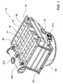
- FIGS. 1 to 7 show a classifier 10 used to separate coal particles, which are located in a coal slurry, on the basis of both size and weight.
- the classifier 10 includes a housing 20, a series of plate arrays 30, a series of launders 40, a series of de-aeration devices 50 and a reservoir 60.
- the housing 20 is used to house the plate arrays 30, launders 40, de-aeration devices 50 and reservoir 60. It should be appreciated that the housing 20 may be shaped and sized differently according to design requirements. It should also be appreciated that a top of the housing 20 is not shown in the FIGS in order to more clearly shown the plate arrays 30 and launders 40.
- Each plate array 30 is made up of a set of spaced apart, parallel inclined plates 31. For clarity, only a minimal number of plates 31 have been illustrated within each plate array 30. It should be appreciated that the number of plates 31, the size of the plates 31, the angle of inclination of the plates 31 and the spacing of the plates 31 can again be varied according to design criteria. Longitudinal members 32 are located on sides of respective sets of plates 30.
- Each launder 40 is formed from a two side walls 41, an inclined base 42 and a series of cross-members 43.
- a collector 70 is formed at the end of the launders 40.
- the collector 70 is located within the housing 20 to collect the coal slurry once it has passed through the launders 40.
- the collector 70 is formed by a pair inclined members 71 that are angled toward each other to form a V-shaped valley.
- a top outlet pipe 72 is connected to the collector 70 at the bottom of the V-shaped valley to transport the slurry for further processing.
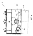
- Each de-aeration device 50 is located below a respective launder 40 and between respective plate arrays 30. It would be appreciated by a person skilled in the art that the number of de-aeration devices is typically the same as the number of launders 40. However, it would also be appreciated that this need not be the case.
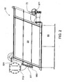
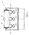
- Each de-aeration device 50 is formed from a slurry inlet 510, a slurry outlet 520, an air outlet 530 and a de-aeration chamber 540.
- the slurry inlet 510 is connected to the de-aeration chamber 540 via an inlet pipe 511 to allow the coal slurry to enter into the de-aeration chamber 540.
- the slurry outlet 520 is located adjacent a bottom of the de-aeration chamber 540 to allow the coal slurry to pass into the reservoir 60.
- a screen 550 is located adjacent the slurry outlet 520 and covers the slurry outlet 520.
- the screen 550 is used to assist in preventing oversize particles from being passed into the reservoir 60.
- the screen 550 is made of wedge wire which extends longitudinally. However, it should be appreciated that the screen 550 may be made from a variety of other materials that a person skilled in the art would appreciate.
- Cleaning hatches 560 are located adjacent an end of the screens to allow access to the screens.
- the screens 550 are removable through respective cleaning hatches in order to clean the screens 550.
- Oversize particle outlets 570 are located at the opposite end of the screens to the cleaning hatches.
- the oversize particle outlets 570 are used to remove oversized particles from a bottom of the de-aeration chamber.
- An over size particle valve 571 may be opened to remove the over size particles through the oversize particle outlet 570.
- a top of each of the de-aeration chambers 50 are inclined and are formed by the inclined bases 42 of the respective launders 40.
- the bottom of the inclined bases form a inclined de-aeration face 580.
- An air outlet 530 is located adjacent an end of the inclined base 42 (and accordingly the de-aeration faces 580) at the top of the de-aeration chamber 50.
- An air pipe 531 is connected to the air outlet 530. It should be appreciated that the tops of the de-aeration chambers 50 need not be formed from the inclined bases of the respective launders 40 and may be formed irrespective of the launders 40. That is, the de-aeration faces 580 may be formed by other means.
- the reservoir 60 is formed in the bottom of the housing 20 and is used to receive the coal slurry after it passes through the de-aeration devices 50. Accordingly, the reservoir 60 is located below the de-aeration chambers 510. The reservoir 60 is also located below the plate arrays 30 and is used to deliver the coal slurry to the plate arrays 30. The longitudinal members 32 of which abut the plates 31 extend into the reservoir 60.
- the coal slurry is passed through a central pipe 512 which divides into the three inlet pipes 511.
- the coal slurry is passed through the slurry inlets 510 into respective de-aeration chambers 540.
- the coal slurry then passes through respective screens 550 which remove oversize particles from the slurry.
- the slurry then passes out of the slurry outlet 520 and into the reservoir 60 located at the bottom of the housing 20.
- the slurry then passes upwardly through the plate arrays 30 where particles located within the coal slurry are sorted according to size and weight.
- the heavy and large particles pass into the bottom of the reservoir 60 where they are removed using a reservoir 60 outlet (not shown).
- the lighter and smaller particles are able to pass through the plates 31 of the plate arrays 30 where they pass into launders 40, into the collector 70 and out of the top outlet pipe 72.
- the removal of air from the slurry provides a number of benefits including a better separation of the particles when the slurry moves through the plate arrays 30 and a likely increased throughput.
Claims (6)
- Classificateur (10) pour classer des particules, le classificateur (10) comprenant :un dispositif de désaération (50) pour désaérer de la pâte comprenant :au moins une chambre de désaération (540) pour positionner une pâte ;au moins une entrée de pâte (510) raccordée à la chambre de désaération (540) pour permettre à la pâte de passer dans la chambre de désaération (540) ;au moins une sortie (520) pour permettre à la pâte de sortir de la chambre de désaération (540) ; etau moins une face de désaération inclinée (580) pour collecter et transporter l'air de la pâte ; etun tamis (550) positionné de manière adjacente à la sortie (520) pour filtrer les grosses particules de la pâte avant que la pâte ne passe par la sortie (520) ; etun dispositif de classification utilisé pour classer la pâte après qu'elle est sortie du dispositif de désaération (50), dans lequel le dispositif de classification comprend une série de groupes de plaques (30) pour recevoir la pâte une fois que la pâte est passée par le dispositif de désaération (50) et dans lequel le dispositif de désaération comprend au moins une rigole (40) pour recevoir la pâte une fois qu'elle est sortie des groupes de plaques (30).
- Classificateur (10) selon la revendication 1, dans lequel le dispositif de classification comprend un réservoir (60) pour recevoir la pâte une fois que la pâte est passée par le dispositif de désaération (50).
- Classificateur (10) selon la revendication 1, dans lequel une base inclinée (42) de la rigole (40) forme la face de désaération inclinée du dispositif de désaération (50).
- Classificateur (10) selon l'une quelconque des revendications 1 à 3, dans lequel le dispositif de désaération (50) comprend en outre une sortie d'air (530) pour permettre à l'air de sortir de la chambre de désaération (540).
- Classificateur (10) selon l'une quelconque des revendications 1 à 4, dans lequel le dispositif de désaération (50) comprend en outre une trappe (560) pour avoir accès au tamis (550).
- Classificateur (10) selon l'une quelconque des revendications 1 à 5, dans lequel le dispositif de désaération (50) comprend en outre une trappe (560) pour retirer le tamis (550).
Applications Claiming Priority (2)
| Application Number | Priority Date | Filing Date | Title |
|---|---|---|---|
| AU2011903462A AU2011903462A0 (en) | 2011-08-29 | A deaerator | |
| PCT/AU2012/001011 WO2013029098A2 (fr) | 2011-08-29 | 2012-08-29 | Dispositif de désaération |
Publications (3)
| Publication Number | Publication Date |
|---|---|
| EP2755734A2 EP2755734A2 (fr) | 2014-07-23 |
| EP2755734A4 EP2755734A4 (fr) | 2015-12-16 |
| EP2755734B1 true EP2755734B1 (fr) | 2017-11-15 |
Family
ID=47756971
Family Applications (1)
| Application Number | Title | Priority Date | Filing Date |
|---|---|---|---|
| EP12828591.3A Active EP2755734B1 (fr) | 2011-08-29 | 2012-08-29 | Dispositif de désaération et classificateur |
Country Status (14)
| Country | Link |
|---|---|
| US (1) | US9283569B2 (fr) |
| EP (1) | EP2755734B1 (fr) |
| CN (1) | CN104254377B (fr) |
| AU (1) | AU2012304261B2 (fr) |
| BR (1) | BR112014004897B1 (fr) |
| CA (1) | CA2864593C (fr) |
| CL (1) | CL2014000488A1 (fr) |
| EA (1) | EA027262B1 (fr) |
| MX (1) | MX350292B (fr) |
| NO (1) | NO2755734T3 (fr) |
| PE (1) | PE20141926A1 (fr) |
| TR (1) | TR201802098T4 (fr) |
| WO (1) | WO2013029098A2 (fr) |
| ZA (1) | ZA201401221B (fr) |
Families Citing this family (5)
| Publication number | Priority date | Publication date | Assignee | Title |
|---|---|---|---|---|
| BR112015027642A2 (pt) * | 2013-05-01 | 2017-08-29 | Smidth As F L | Classificador |
| AU2013388349A1 (en) * | 2013-05-01 | 2015-11-12 | Flsmidth A/S | Classifier |
| CN105813724B (zh) * | 2013-11-14 | 2017-12-05 | Fl史密斯公司 | 分选机 |
| CN113634363A (zh) | 2016-04-26 | 2021-11-12 | 纽卡斯尔创新有限公司 | 用于颗粒分离器的进料装置、颗粒分离器和颗粒分离方法 |
| AU2020308091B2 (en) * | 2019-06-28 | 2023-02-23 | Flsmidth A/S | Separator apparatus and feed arrangement for increased capacity |
Citations (3)
| Publication number | Priority date | Publication date | Assignee | Title |
|---|---|---|---|---|
| GB1589600A (en) * | 1976-09-09 | 1981-05-13 | Sigma Z Na Vyrobu Cerpacich Za | Separating solid particles from a liquid suspension |
| US4834783A (en) * | 1988-05-09 | 1989-05-30 | Consolidation Coal Company | Rotary separator |
| US20030098277A1 (en) * | 2001-11-24 | 2003-05-29 | Khudenko Boris M. | Sweetening of mixed liquor during solid-liquid separation |
Family Cites Families (14)
| Publication number | Priority date | Publication date | Assignee | Title |
|---|---|---|---|---|
| US3006561A (en) * | 1960-04-11 | 1961-10-31 | Scott Paper Co | Disintegration of resin foams |
| US3771290A (en) * | 1971-12-06 | 1973-11-13 | Armstrong Ltd S A | Vortex de-aerator |
| US4214879A (en) * | 1978-12-26 | 1980-07-29 | George W. Tillett | Degassing apparatus |
| CA1111784A (fr) | 1979-05-23 | 1981-11-03 | Elast-O-Cor Products & Engineering Limited | Degazeur de pate a papier |
| HU195258B (en) | 1985-04-01 | 1988-04-28 | Fki Aluminiumipari Tervezoe Es | Process and hydroseparator for the separation of mixed hydrate pulp of alumina factories |
| FI872967A (fi) * | 1987-07-06 | 1989-01-07 | Ahlstroem Oy | Pump och foerfarande foer separering av gas med pumpen ur mediet som skall pumpas. |
| US4871449A (en) * | 1988-06-27 | 1989-10-03 | Lott W Gerald | Clarifier and screw compactor liquid-solid separator |
| CN2407814Y (zh) * | 2000-01-28 | 2000-11-29 | 张朝明 | 气水分离集气装置 |
| EP1208897A1 (fr) * | 2000-11-21 | 2002-05-29 | Epcon Norge AS | Réservoir pour flottation et dégazage combiné |
| CA2387257C (fr) * | 2002-05-23 | 2009-07-28 | Suncor Energy Inc. | Conditionneur fixe de desaeration pour le traitement de la mousse de bitume |
| US7361282B2 (en) * | 2003-07-21 | 2008-04-22 | Smullin Corporation | Separator of floating components |
| JP2007275866A (ja) | 2006-03-16 | 2007-10-25 | Ngk Insulators Ltd | スラリーの脱泡方法及び装置 |
| US8128786B2 (en) * | 2009-03-02 | 2012-03-06 | Harris Corporation | RF heating to reduce the use of supplemental water added in the recovery of unconventional oil |
| SE534401C2 (sv) | 2009-12-28 | 2011-08-09 | Metso Paper Karlstad Ab | Enhet och förfarande för avluftning av dränagevatten |
-
2012
- 2012-08-29 TR TR2018/02098T patent/TR201802098T4/tr unknown
- 2012-08-29 WO PCT/AU2012/001011 patent/WO2013029098A2/fr active Application Filing
- 2012-08-29 CN CN201280041635.5A patent/CN104254377B/zh active Active
- 2012-08-29 NO NO12828591A patent/NO2755734T3/no unknown
- 2012-08-29 MX MX2014002201A patent/MX350292B/es active IP Right Grant
- 2012-08-29 EP EP12828591.3A patent/EP2755734B1/fr active Active
- 2012-08-29 BR BR112014004897-5A patent/BR112014004897B1/pt active IP Right Grant
- 2012-08-29 AU AU2012304261A patent/AU2012304261B2/en active Active
- 2012-08-29 CA CA2864593A patent/CA2864593C/fr active Active
- 2012-08-29 PE PE2014000278A patent/PE20141926A1/es active IP Right Grant
- 2012-08-29 US US14/241,603 patent/US9283569B2/en active Active
- 2012-08-29 EA EA201400261A patent/EA027262B1/ru not_active IP Right Cessation
-
2014
- 2014-02-18 ZA ZA2014/01221A patent/ZA201401221B/en unknown
- 2014-02-27 CL CL2014000488A patent/CL2014000488A1/es unknown
Patent Citations (3)
| Publication number | Priority date | Publication date | Assignee | Title |
|---|---|---|---|---|
| GB1589600A (en) * | 1976-09-09 | 1981-05-13 | Sigma Z Na Vyrobu Cerpacich Za | Separating solid particles from a liquid suspension |
| US4834783A (en) * | 1988-05-09 | 1989-05-30 | Consolidation Coal Company | Rotary separator |
| US20030098277A1 (en) * | 2001-11-24 | 2003-05-29 | Khudenko Boris M. | Sweetening of mixed liquor during solid-liquid separation |
Also Published As
| Publication number | Publication date |
|---|---|
| CA2864593C (fr) | 2016-01-12 |
| CN104254377A (zh) | 2014-12-31 |
| CA2864593A1 (fr) | 2013-03-07 |
| ZA201401221B (en) | 2015-05-27 |
| CL2014000488A1 (es) | 2014-08-22 |
| EA027262B1 (ru) | 2017-07-31 |
| WO2013029098A2 (fr) | 2013-03-07 |
| EA201400261A1 (ru) | 2014-09-30 |
| US20140216986A1 (en) | 2014-08-07 |
| NZ621104A (en) | 2016-09-30 |
| BR112014004897A2 (pt) | 2017-03-21 |
| WO2013029098A3 (fr) | 2014-09-25 |
| CN104254377B (zh) | 2016-08-31 |
| BR112014004897B1 (pt) | 2021-02-23 |
| EP2755734A2 (fr) | 2014-07-23 |
| EP2755734A4 (fr) | 2015-12-16 |
| AU2012304261B2 (en) | 2014-04-24 |
| NO2755734T3 (fr) | 2018-04-14 |
| PE20141926A1 (es) | 2014-12-17 |
| MX350292B (es) | 2017-09-04 |
| MX2014002201A (es) | 2015-02-09 |
| TR201802098T4 (tr) | 2018-03-21 |
| US9283569B2 (en) | 2016-03-15 |
| AU2012304261A1 (en) | 2014-03-06 |
Similar Documents
| Publication | Publication Date | Title |
|---|---|---|
| EP2755734B1 (fr) | Dispositif de désaération et classificateur | |
| AU2013388348B2 (en) | Classifier | |
| RU2639005C1 (ru) | Классификатор | |
| US10081019B1 (en) | Modular portable sluice box | |
| CA2910608C (fr) | Classificateur | |
| US20190047022A1 (en) | Gyratory Sifter Side Fines Chutes | |
| WO2018202711A1 (fr) | Plaque déflectrice pour classificateur | |
| NZ621104B2 (en) | A de-aeration device | |
| RU2365431C1 (ru) | Пневмосепаратор зернового материала | |
| CN204544403U (zh) | 综合力场多流态重选机 | |
| EP3031506A1 (fr) | Cyclofiltre avec une batterie de cyclones dotée d'une distribution de poussière latérale | |
| CN202516678U (zh) | 一种新型高效斜板沉降分级浓密机 | |
| JP5964707B2 (ja) | 沈砂分離装置 | |
| CN110022994A (zh) | 分离矿物原料的气动方法 |
Legal Events
| Date | Code | Title | Description |
|---|---|---|---|
| PUAI | Public reference made under article 153(3) epc to a published international application that has entered the european phase |
Free format text: ORIGINAL CODE: 0009012 |
|
| 17P | Request for examination filed |
Effective date: 20140328 |
|
| AK | Designated contracting states |
Kind code of ref document: A2 Designated state(s): AL AT BE BG CH CY CZ DE DK EE ES FI FR GB GR HR HU IE IS IT LI LT LU LV MC MK MT NL NO PL PT RO RS SE SI SK SM TR |
|
| RAP1 | Party data changed (applicant data changed or rights of an application transferred) |
Owner name: FLSMIDTH A/S |
|
| R17D | Deferred search report published (corrected) |
Effective date: 20140925 |
|
| DAX | Request for extension of the european patent (deleted) | ||
| A4 | Supplementary search report drawn up and despatched |
Effective date: 20151113 |
|
| RIC1 | Information provided on ipc code assigned before grant |
Ipc: B01D 21/00 20060101ALI20151109BHEP Ipc: B01D 19/00 20060101AFI20151109BHEP Ipc: B03B 5/62 20060101ALI20151109BHEP Ipc: B01D 21/24 20060101ALI20151109BHEP Ipc: B03D 1/02 20060101ALI20151109BHEP |
|
| 17Q | First examination report despatched |
Effective date: 20160623 |
|
| GRAP | Despatch of communication of intention to grant a patent |
Free format text: ORIGINAL CODE: EPIDOSNIGR1 |
|
| INTG | Intention to grant announced |
Effective date: 20170612 |
|
| GRAS | Grant fee paid |
Free format text: ORIGINAL CODE: EPIDOSNIGR3 |
|
| GRAA | (expected) grant |
Free format text: ORIGINAL CODE: 0009210 |
|
| AK | Designated contracting states |
Kind code of ref document: B1 Designated state(s): AL AT BE BG CH CY CZ DE DK EE ES FI FR GB GR HR HU IE IS IT LI LT LU LV MC MK MT NL NO PL PT RO RS SE SI SK SM TR |
|
| REG | Reference to a national code |
Ref country code: CH Ref legal event code: EP Ref country code: GB Ref legal event code: FG4D Ref country code: AT Ref legal event code: REF Ref document number: 945702 Country of ref document: AT Kind code of ref document: T Effective date: 20171115 |
|
| REG | Reference to a national code |
Ref country code: IE Ref legal event code: FG4D |
|
| REG | Reference to a national code |
Ref country code: DE Ref legal event code: R096 Ref document number: 602012039919 Country of ref document: DE |
|
| REG | Reference to a national code |
Ref country code: SE Ref legal event code: TRGR |
|
| REG | Reference to a national code |
Ref country code: NL Ref legal event code: MP Effective date: 20171115 |
|
| REG | Reference to a national code |
Ref country code: LT Ref legal event code: MG4D Ref country code: NO Ref legal event code: T2 Effective date: 20171115 |
|
| REG | Reference to a national code |
Ref country code: AT Ref legal event code: MK05 Ref document number: 945702 Country of ref document: AT Kind code of ref document: T Effective date: 20171115 |
|
| PG25 | Lapsed in a contracting state [announced via postgrant information from national office to epo] |
Ref country code: LT Free format text: LAPSE BECAUSE OF FAILURE TO SUBMIT A TRANSLATION OF THE DESCRIPTION OR TO PAY THE FEE WITHIN THE PRESCRIBED TIME-LIMIT Effective date: 20171115 Ref country code: ES Free format text: LAPSE BECAUSE OF FAILURE TO SUBMIT A TRANSLATION OF THE DESCRIPTION OR TO PAY THE FEE WITHIN THE PRESCRIBED TIME-LIMIT Effective date: 20171115 Ref country code: NL Free format text: LAPSE BECAUSE OF FAILURE TO SUBMIT A TRANSLATION OF THE DESCRIPTION OR TO PAY THE FEE WITHIN THE PRESCRIBED TIME-LIMIT Effective date: 20171115 |
|
| PG25 | Lapsed in a contracting state [announced via postgrant information from national office to epo] |
Ref country code: LV Free format text: LAPSE BECAUSE OF FAILURE TO SUBMIT A TRANSLATION OF THE DESCRIPTION OR TO PAY THE FEE WITHIN THE PRESCRIBED TIME-LIMIT Effective date: 20171115 Ref country code: AT Free format text: LAPSE BECAUSE OF FAILURE TO SUBMIT A TRANSLATION OF THE DESCRIPTION OR TO PAY THE FEE WITHIN THE PRESCRIBED TIME-LIMIT Effective date: 20171115 Ref country code: GR Free format text: LAPSE BECAUSE OF FAILURE TO SUBMIT A TRANSLATION OF THE DESCRIPTION OR TO PAY THE FEE WITHIN THE PRESCRIBED TIME-LIMIT Effective date: 20180216 Ref country code: BG Free format text: LAPSE BECAUSE OF FAILURE TO SUBMIT A TRANSLATION OF THE DESCRIPTION OR TO PAY THE FEE WITHIN THE PRESCRIBED TIME-LIMIT Effective date: 20180215 Ref country code: RS Free format text: LAPSE BECAUSE OF FAILURE TO SUBMIT A TRANSLATION OF THE DESCRIPTION OR TO PAY THE FEE WITHIN THE PRESCRIBED TIME-LIMIT Effective date: 20171115 Ref country code: HR Free format text: LAPSE BECAUSE OF FAILURE TO SUBMIT A TRANSLATION OF THE DESCRIPTION OR TO PAY THE FEE WITHIN THE PRESCRIBED TIME-LIMIT Effective date: 20171115 |
|
| PG25 | Lapsed in a contracting state [announced via postgrant information from national office to epo] |
Ref country code: DK Free format text: LAPSE BECAUSE OF FAILURE TO SUBMIT A TRANSLATION OF THE DESCRIPTION OR TO PAY THE FEE WITHIN THE PRESCRIBED TIME-LIMIT Effective date: 20171115 Ref country code: EE Free format text: LAPSE BECAUSE OF FAILURE TO SUBMIT A TRANSLATION OF THE DESCRIPTION OR TO PAY THE FEE WITHIN THE PRESCRIBED TIME-LIMIT Effective date: 20171115 Ref country code: CY Free format text: LAPSE BECAUSE OF FAILURE TO SUBMIT A TRANSLATION OF THE DESCRIPTION OR TO PAY THE FEE WITHIN THE PRESCRIBED TIME-LIMIT Effective date: 20171115 Ref country code: CZ Free format text: LAPSE BECAUSE OF FAILURE TO SUBMIT A TRANSLATION OF THE DESCRIPTION OR TO PAY THE FEE WITHIN THE PRESCRIBED TIME-LIMIT Effective date: 20171115 Ref country code: SK Free format text: LAPSE BECAUSE OF FAILURE TO SUBMIT A TRANSLATION OF THE DESCRIPTION OR TO PAY THE FEE WITHIN THE PRESCRIBED TIME-LIMIT Effective date: 20171115 |
|
| REG | Reference to a national code |
Ref country code: DE Ref legal event code: R097 Ref document number: 602012039919 Country of ref document: DE |
|
| PG25 | Lapsed in a contracting state [announced via postgrant information from national office to epo] |
Ref country code: SM Free format text: LAPSE BECAUSE OF FAILURE TO SUBMIT A TRANSLATION OF THE DESCRIPTION OR TO PAY THE FEE WITHIN THE PRESCRIBED TIME-LIMIT Effective date: 20171115 Ref country code: IT Free format text: LAPSE BECAUSE OF FAILURE TO SUBMIT A TRANSLATION OF THE DESCRIPTION OR TO PAY THE FEE WITHIN THE PRESCRIBED TIME-LIMIT Effective date: 20171115 Ref country code: RO Free format text: LAPSE BECAUSE OF FAILURE TO SUBMIT A TRANSLATION OF THE DESCRIPTION OR TO PAY THE FEE WITHIN THE PRESCRIBED TIME-LIMIT Effective date: 20171115 Ref country code: PL Free format text: LAPSE BECAUSE OF FAILURE TO SUBMIT A TRANSLATION OF THE DESCRIPTION OR TO PAY THE FEE WITHIN THE PRESCRIBED TIME-LIMIT Effective date: 20171115 |
|
| PLBE | No opposition filed within time limit |
Free format text: ORIGINAL CODE: 0009261 |
|
| STAA | Information on the status of an ep patent application or granted ep patent |
Free format text: STATUS: NO OPPOSITION FILED WITHIN TIME LIMIT |
|
| 26N | No opposition filed |
Effective date: 20180817 |
|
| PG25 | Lapsed in a contracting state [announced via postgrant information from national office to epo] |
Ref country code: SI Free format text: LAPSE BECAUSE OF FAILURE TO SUBMIT A TRANSLATION OF THE DESCRIPTION OR TO PAY THE FEE WITHIN THE PRESCRIBED TIME-LIMIT Effective date: 20171115 |
|
| REG | Reference to a national code |
Ref country code: DE Ref legal event code: R119 Ref document number: 602012039919 Country of ref document: DE |
|
| PG25 | Lapsed in a contracting state [announced via postgrant information from national office to epo] |
Ref country code: MC Free format text: LAPSE BECAUSE OF FAILURE TO SUBMIT A TRANSLATION OF THE DESCRIPTION OR TO PAY THE FEE WITHIN THE PRESCRIBED TIME-LIMIT Effective date: 20171115 |
|
| REG | Reference to a national code |
Ref country code: CH Ref legal event code: PL |
|
| GBPC | Gb: european patent ceased through non-payment of renewal fee |
Effective date: 20180829 |
|
| PG25 | Lapsed in a contracting state [announced via postgrant information from national office to epo] |
Ref country code: CH Free format text: LAPSE BECAUSE OF NON-PAYMENT OF DUE FEES Effective date: 20180831 Ref country code: LI Free format text: LAPSE BECAUSE OF NON-PAYMENT OF DUE FEES Effective date: 20180831 Ref country code: LU Free format text: LAPSE BECAUSE OF NON-PAYMENT OF DUE FEES Effective date: 20180829 |
|
| REG | Reference to a national code |
Ref country code: BE Ref legal event code: MM Effective date: 20180831 |
|
| PG25 | Lapsed in a contracting state [announced via postgrant information from national office to epo] |
Ref country code: DE Free format text: LAPSE BECAUSE OF NON-PAYMENT OF DUE FEES Effective date: 20190301 |
|
| PG25 | Lapsed in a contracting state [announced via postgrant information from national office to epo] |
Ref country code: BE Free format text: LAPSE BECAUSE OF NON-PAYMENT OF DUE FEES Effective date: 20180831 Ref country code: FR Free format text: LAPSE BECAUSE OF NON-PAYMENT OF DUE FEES Effective date: 20180831 |
|
| PG25 | Lapsed in a contracting state [announced via postgrant information from national office to epo] |
Ref country code: GB Free format text: LAPSE BECAUSE OF NON-PAYMENT OF DUE FEES Effective date: 20180829 |
|
| PG25 | Lapsed in a contracting state [announced via postgrant information from national office to epo] |
Ref country code: MT Free format text: LAPSE BECAUSE OF NON-PAYMENT OF DUE FEES Effective date: 20180829 |
|
| PG25 | Lapsed in a contracting state [announced via postgrant information from national office to epo] |
Ref country code: PT Free format text: LAPSE BECAUSE OF FAILURE TO SUBMIT A TRANSLATION OF THE DESCRIPTION OR TO PAY THE FEE WITHIN THE PRESCRIBED TIME-LIMIT Effective date: 20171115 Ref country code: HU Free format text: LAPSE BECAUSE OF FAILURE TO SUBMIT A TRANSLATION OF THE DESCRIPTION OR TO PAY THE FEE WITHIN THE PRESCRIBED TIME-LIMIT; INVALID AB INITIO Effective date: 20120829 |
|
| PG25 | Lapsed in a contracting state [announced via postgrant information from national office to epo] |
Ref country code: MK Free format text: LAPSE BECAUSE OF NON-PAYMENT OF DUE FEES Effective date: 20171115 Ref country code: IE Free format text: LAPSE BECAUSE OF NON-PAYMENT OF DUE FEES Effective date: 20180829 |
|
| PG25 | Lapsed in a contracting state [announced via postgrant information from national office to epo] |
Ref country code: AL Free format text: LAPSE BECAUSE OF FAILURE TO SUBMIT A TRANSLATION OF THE DESCRIPTION OR TO PAY THE FEE WITHIN THE PRESCRIBED TIME-LIMIT Effective date: 20171115 Ref country code: IS Free format text: LAPSE BECAUSE OF FAILURE TO SUBMIT A TRANSLATION OF THE DESCRIPTION OR TO PAY THE FEE WITHIN THE PRESCRIBED TIME-LIMIT Effective date: 20180315 |
|
| P01 | Opt-out of the competence of the unified patent court (upc) registered |
Effective date: 20230507 |
|
| PGFP | Annual fee paid to national office [announced via postgrant information from national office to epo] |
Ref country code: TR Payment date: 20230828 Year of fee payment: 12 Ref country code: NO Payment date: 20230809 Year of fee payment: 12 Ref country code: FI Payment date: 20230816 Year of fee payment: 12 |
|
| PGFP | Annual fee paid to national office [announced via postgrant information from national office to epo] |
Ref country code: SE Payment date: 20230710 Year of fee payment: 12 |