EP2755462A2 - Electronic component mounting apparatus - Google Patents
Electronic component mounting apparatus Download PDFInfo
- Publication number
- EP2755462A2 EP2755462A2 EP13005994.2A EP13005994A EP2755462A2 EP 2755462 A2 EP2755462 A2 EP 2755462A2 EP 13005994 A EP13005994 A EP 13005994A EP 2755462 A2 EP2755462 A2 EP 2755462A2
- Authority
- EP
- European Patent Office
- Prior art keywords
- unit
- printed circuit
- circuit board
- substrate
- electronic component
- Prior art date
- Legal status (The legal status is an assumption and is not a legal conclusion. Google has not performed a legal analysis and makes no representation as to the accuracy of the status listed.)
- Granted
Links
Images








Classifications
-
- H—ELECTRICITY
- H05—ELECTRIC TECHNIQUES NOT OTHERWISE PROVIDED FOR
- H05K—PRINTED CIRCUITS; CASINGS OR CONSTRUCTIONAL DETAILS OF ELECTRIC APPARATUS; MANUFACTURE OF ASSEMBLAGES OF ELECTRICAL COMPONENTS
- H05K13/00—Apparatus or processes specially adapted for manufacturing or adjusting assemblages of electric components
- H05K13/04—Mounting of components, e.g. of leadless components
-
- H—ELECTRICITY
- H05—ELECTRIC TECHNIQUES NOT OTHERWISE PROVIDED FOR
- H05K—PRINTED CIRCUITS; CASINGS OR CONSTRUCTIONAL DETAILS OF ELECTRIC APPARATUS; MANUFACTURE OF ASSEMBLAGES OF ELECTRICAL COMPONENTS
- H05K13/00—Apparatus or processes specially adapted for manufacturing or adjusting assemblages of electric components
- H05K13/0061—Tools for holding the circuit boards during processing; handling transport of printed circuit boards
-
- Y—GENERAL TAGGING OF NEW TECHNOLOGICAL DEVELOPMENTS; GENERAL TAGGING OF CROSS-SECTIONAL TECHNOLOGIES SPANNING OVER SEVERAL SECTIONS OF THE IPC; TECHNICAL SUBJECTS COVERED BY FORMER USPC CROSS-REFERENCE ART COLLECTIONS [XRACs] AND DIGESTS
- Y10—TECHNICAL SUBJECTS COVERED BY FORMER USPC
- Y10T—TECHNICAL SUBJECTS COVERED BY FORMER US CLASSIFICATION
- Y10T29/00—Metal working
- Y10T29/53—Means to assemble or disassemble
- Y10T29/5313—Means to assemble electrical device
- Y10T29/53174—Means to fasten electrical component to wiring board, base, or substrate
- Y10T29/53178—Chip component
Definitions
- the present invention relates to an electronic component mounting apparatus which mounts an electronic component on a printed circuit board.
- a conventional general electronic component mounting apparatus (to be simply referred to as a mounting apparatus hereinafter) includes a conveyance device which horizontally feeds a printed circuit board. Also, in the conventional electronic component mounting apparatus, a printed circuit board loading unit, a substrate holding unit on which a printed circuit board is held at the time of mounting, and a printed circuit board unloading unit are aligned in a line in the conveyance direction of the conveyance device.
- An electronic component mounting apparatus of this type adopts a form shown in, for example, Japanese Patent No. 4278903 (to be simply referred to as literature 1 hereinafter) or Japanese Patent Laid-Open No. 2003-163498 (to be simply referred to as literature 2 hereinafter) to obtain a high productivity.
- Literature 1 discloses a mounting system formed by aligning a plurality of mounting apparatuses in a line in the conveyance direction.
- the mounting apparatus disclosed in literature 1 includes two conveyance devices. These conveyance devices serve to divert a mounting apparatus, that has generated a delay in mounting, of a plurality of mounting apparatuses to feed a printed circuit board to the downstream mounting apparatus. These conveyance devices are aligned in one horizontal direction perpendicular to the conveyance direction. Also, distribution conveyors are connected to the upstream and downstream ends of these conveyance devices to allow selection of a conveyance device to which a printed circuit board is conveyed.
- Literature 2 discloses a mounting system formed by aligning a plurality of mounting apparatuses in a line in a horizontal direction perpendicular to the conveyance direction.
- the conveyance devices for each mounting apparatus disclosed in literature 2 are connected to each other by a loading conveyor and an unloading conveyor.
- the unloading conveyor can feed printed circuit boards to the upstream ends of all conveyance devices.
- the unloading conveyor can receive printed circuit boards from the downstream ends of all conveyance devices.
- the present invention has been made to solve such problems, and has as its object to provide an electronic component mounting apparatus that is compact in the conveyance direction of a conveyance device for conveying a printed circuit board.
- an electronic component mounting apparatus comprising a loading unit which moves a printed circuit board in a first horizontal direction to load the printed circuit board, a first substrate moving unit which moves the printed circuit board, loaded by the loading unit, in a second horizontal direction perpendicular to the first horizontal direction, a substrate holding unit which temporarily holds the printed circuit board moved by the first substrate moving unit, a component mounting unit which mounts an electronic component on the printed circuit board held by the substrate holding unit, a second substrate moving unit which moves the printed circuit board with the electronic component mounted thereon in the second horizontal direction, and an unloading unit which moves the printed circuit board, moved by the second substrate moving unit, in the first horizontal direction to unload the printed circuit board.
- An electronic component mounting apparatus 1 shown in Fig. 1 is built by placing various devices (to be described later) on one base 2. Although details will be described later, the various devices include devices that constitute a substrate conveyance unit 4 which conveys a printed circuit board 3, and devices that constitute a component mounting unit 5 which mounts an electronic component (not shown).
- the substrate conveyance unit 4 has a function of conveying the printed circuit board 3 on the base 2 in first and second horizontal directions that are orthogonal to each other, as shown in Figs. 1 and 2 .
- the first horizontal direction is the direction from the left to the right in Figs. 1 and 2
- the second horizontal direction is the direction from the bottom to the top in Figs. 1 and 2 .
- the first horizontal direction will be simply referred to as the X-direction
- the second horizontal direction will be simply referred to as the Y-direction.
- the left side will be referred to as the upstream side in the X-direction in Figs.
- the right side will be referred to as the downstream side in the X-direction in Figs. 1 and 2 .
- the lower side will be referred to as the upstream side in the Y-direction in Figs. 1 and 2
- the upper side will be referred to as the downstream side in the Y-direction in Figs. 1 and 2 .
- the substrate conveyance unit 4 includes a loading unit 11, substrate holding unit 12, and unloading unit 13 which are aligned in the Y-direction on the base 2, and a first substrate moving unit 14 and second substrate moving unit 15 which move the printed circuit board 3 in the Y-direction between the units 11, 12, and 13.
- the loading unit 11 includes a conveyor 16 for loading the printed circuit board 3.
- the conveyor 16 is disposed at the upstream end in the Y-direction (the lower end in Figs. 1 and 2 ) on the base 2, and traverses the base 2 in the X-direction.
- the printed circuit board 3 is fed from a device in the previous step to the upstream end in the X-direction on the conveyor 16, and fed onto the base 2 by the conveyor 16.
- the conveyor 16 feeds the printed circuit board 3 in the X-direction on a predetermined substrate movement surface.
- the substrate holding unit 12 includes a conveyor 17 capable of feeding the printed circuit board 3 in the X-direction, and a mounting stage 18 positioned inside the conveyor 17.
- the mounting stage 18 has a structure which can temporarily hold the printed circuit board 3 on a predetermined substrate support surface.
- the printed circuit board 3 loaded by the loading unit 11 moves onto the substrate holding unit 12 by a device that constitutes the first substrate moving unit 14 (to be described later).
- the first substrate moving unit 14 includes a moving member (not shown) which moves in the Y-direction as the printed circuit board 3 is placed on it.
- the printed circuit board 3 placed on the moving member moves from the loading unit 11 to the substrate holding unit 12.
- belts for example, can be used.
- the first substrate moving unit 14 has not only a function of moving the moving member in the Y-direction, but also a function of lifting or lowering it.
- the moving member ascends or descends between a substrate transfer position higher than the substrate movement surface of the loading unit 11 and the substrate support surface of the substrate holding unit 12, and a standby position lower than this substrate movement surface and substrate support surface.
- the substrate transfer position corresponds to a "first position" according to the invention defined in claim 5
- the standby position corresponds to a "second position" according to the invention defined in claim 5.
- the unloading unit 13 includes a conveyor 19 which unloads the printed circuit board 3 in the X-direction from the downstream end in the Y-direction (the upper end in Figs. 1 and 2 ) on the base 2.
- the conveyor 19 traverses the base 2 in the X-direction.
- the printed circuit board 3 has an electronic component mounted thereon is released by the substrate holding unit 12, and moves to the unloading unit 13 from the substrate holding unit 12 by the second substrate moving unit 15 (to be described later).
- the second substrate moving unit 15 includes a guide member (not shown) extending in the Y-direction, and a moving mechanism (not shown).
- the moving mechanism translates the member (conveyor 17) and mounting stage 18, on which the printed circuit board 3 is placed by the substrate holding unit 12, in the Y-direction together with the printed circuit board 3.
- the conveyor 17 and mounting stage 18 are movably supported by the guide member extending in the Y-direction, and reciprocally move between a mounting position shown in Figs. 1 and 2 , and an unloading position (not shown) in the unloading unit 13 upon being driven by the moving mechanism.
- the conveyor 17 of the substrate holding unit 12 moves into the unloading unit 13 to be connected to the conveyor 19 of the unloading unit 13 so that the printed circuit board 3 can be fed to the conveyor 19 of the unloading unit 13.
- the component mounting unit 5 mounts an electronic component on the printed circuit board 3 held to the mounting stage 18 mentioned above.
- the component mounting unit 5 includes component supply devices 21 placed at the upstream and downstream ends of the base 2 in the Y-direction, and a component moving device 22 which moves an electronic component from the component supply device 21 to the printed circuit board 3, as shown in Fig. 1 .
- the component supply device 21 is built by a large number of tape feeders 21a in this embodiment.
- a camera 23 for capturing an image of an electronic component from below is provided between the component supply device 21 and the substrate conveyance unit 4.
- the component moving device 22 includes a pair of Y beams 24 extending in the Y-direction on the base 2, and an X beam 25 bridging the Y beams 24.
- the X beam 25 moves in a direction parallel to the Y-direction upon being driven by a Y driving device 26.
- the X beam 25 is provided with a head unit 27 movable in a direction parallel to the X-direction.
- the head unit 27 has a plurality of suction heads 27a, and moves in a direction parallel to the X-direction upon being driven by an X driving device 28.
- the suction head 27a has a suction nozzle (not shown) at its lower end, and is supported on the head unit 27 to be liftable and rotatable about a vertical axis.
- the suction heads 27a move between the two component supply devices 21 and the printed circuit board 3 held on the substrate holding unit 12 as the head unit 27 moves in the X- and Y-directions. Therefore, the second substrate moving unit 15 is positioned to fall within the range in which an electronic component can be mounted by the component mounting unit 5.
- the printed circuit board 3 loaded by the loading unit 11 is moved in the Y-direction by the first substrate moving unit 14, fed to the substrate holding unit 12, and held by the substrate holding unit 12.
- an electronic component is removed from the component supply devices 21 and mounted on the printed circuit board 3 by the component mounting unit 5.
- the printed circuit board 3 is fed to the unloading unit 13 by the second substrate moving unit 15 and unloaded in the X-direction by the unloading unit 13.
- the loading unit 11, first substrate moving unit 14, substrate holding unit 12, second substrate moving unit 15, and unloading unit 13 are aligned in a line in the Y-direction.
- an electronic component mounting apparatus more compact in the X-direction can be provided by adopting this embodiment.
- the second substrate moving unit 15 includes a moving mechanism which translates the member (conveyor 17), on which the printed circuit board 3 is placed, together with the printed circuit board 3 along a guide member extending in the Y-direction.
- a printed circuit board 3 on which a component has been mounted can be moved in the Y-direction and fed to the unloading unit 13 without being affected by large vibration.
- the electronic component does not shift from the position at which it was mounted due to vibration or impact, so an electronic component mounting apparatus capable of high-quality component mounting can be provided.
- the first substrate moving unit 14 uses a moving member which moves in the Y-direction to feed the printed circuit board 3 from the loading unit 11 to the substrate holding unit 12.
- the moving member ascends or descends between a substrate transfer position higher than the substrate movement surface of the loading unit 11 and the substrate support surface of the substrate holding unit 12, and a standby position lower than this substrate movement surface and substrate support surface.
- the moving member ascends from the standby position to the substrate transfer position and moves in the Y-direction to feed the printed circuit board 3 to the substrate holding unit 12 at once while avoiding interference between the loading unit 11 and the substrate holding unit 12.
- the printed circuit board 3 can be quickly fed from the loading unit 11 to the substrate holding unit 12, an electronic component mounting apparatus with a higher productivity can be provided.
- the second substrate moving unit 15 is positioned to fall within the range in which an electronic component can be mounted by the component mounting unit 5.
- an electronic component can be mounted on the printed circuit board 3 by the component mounting unit 5 between the substrate holding unit 12 and the unloading unit 13 as well.
- An electronic component mounting apparatus can be used to build a mounting system, as shown in Fig. 3 .
- a mounting system 29 shown in Fig. 3 is formed by aligning a plurality of (three) electronic component mounting apparatuses 1 in the X-direction. Note that Fig. 3 does not illustrate a component mounting unit 5 of each electronic component mounting apparatus 1. Loading units 11 of the electronic component mounting apparatuses 1 are connected to each other so as to feed a printed circuit board 3 in the X-direction. Also, unloading units 13 of the electronic component mounting apparatuses 1 are connected to each other so as to feed a printed circuit board 3 in the X-direction.
- the printed circuit board 3 can be fed to all electronic component mounting apparatuses 1 using the loading unit 11 of each electronic component mounting apparatus 1. Again, with the mounting system 29, the printed circuit board 3 can be unloaded from all electronic component mounting apparatuses 1 using the unloading unit 13 of each electronic component mounting apparatus 1. The printed circuit board 3 moves in the Y-direction from the loading unit 11 in each electronic component mounting apparatus 1 and is fed to the substrate holding unit 12.
- loading of a printed circuit board 3, mounting of an electronic component, and unloading of the printed circuit board 3 can be independently done in each electronic component mounting apparatus 1 without influencing the mounting states of other electronic component mounting apparatuses 1.
- a mounting system which not only is compact in the X-direction but also has a high mounting efficiency can be provided.
- a substrate conveyance unit 4 of an electronic component mounting apparatus 31 shown in Fig. 4 can feed a printed circuit board 3 to the downstream and upstream sides in the X-direction in a substrate holding unit 12. That is, the substrate conveyance unit 4 includes a first conveyance lane (conveyance path) L1 formed by a loading unit 11, a second conveyance lane L2 formed by the substrate holding unit 12, and a third conveyance lane L3 formed by an unloading unit 13 so as to be aligned in the Y-direction in this order.
- a first conveyance lane (conveyance path) L1 formed by a loading unit 11, a second conveyance lane L2 formed by the substrate holding unit 12, and a third conveyance lane L3 formed by an unloading unit 13 so as to be aligned in the Y-direction in this order.
- the second conveyance lane L2 (substrate holding unit 12) is built by a moving direction change conveyor 32 positioned at the center of a base 2 in the X-direction, and a conveyor 17 and mounting stage 18 provided on each side of the moving direction change conveyor 32.
- a "first conveyor” according to the invention defined in claim 2 is implemented by the moving direction change conveyor 32.
- the moving direction change conveyor 32 rotates a pair of belts extending parallel to the X-direction to feed the printed circuit board 3 in a direction parallel to the X-direction.
- the printed circuit board 3 is fed from the first conveyance lane (conveyance path) L1 to the second conveyance lane L2 by a first substrate moving unit 14, and then fed to the downstream side in the X-direction (the right side in Figs. 4 and 5 ) or the upstream side in the X-direction (the left side in Figs. 4 and 5 ) by the moving direction change conveyor 32. That is, the moving direction change conveyor 32 changes the conveyance direction of the printed circuit board 3 fed by the first substrate moving unit 14 to the X-direction or a direction opposite to the X-direction.
- the mounting stage 18 according to this embodiment is equivalent to that shown in the first embodiment, and the printed circuit board 3 fed by the moving direction change conveyor 32 and conveyor 17 on the second conveyance lane L2 are temporarily held.
- a second substrate moving unit 15 according to this embodiment is provided on each side of the moving direction change conveyor 32, and feeds the mounting stage 18 in the Y-direction.
- the mounting stage 18 is reciprocally moved between the second conveyance lane L2 and the third conveyance lane L3 by the second substrate moving unit 15.
- the unloading unit 13 adopts an arrangement which feeds, in the X-direction, the printed circuit board 3 fed to the third conveyance lane L3 by one second substrate moving unit 15, and the printed circuit board 3 fed to the third conveyance lane L3 by the other second substrate moving unit 15.
- a component mounting unit 5 includes two head units 27, as shown in Fig. 4 .
- the head units 27 are supported by X beams 25 to be movable in the X-direction.
- the X beam 25 for each head unit is supported by a Y beam 24 to be movable in a direction parallel to the Y-direction.
- Fig. 4 does not illustrate Y beams which support the adjacent ends of the two X beams 25.
- the range in which each head unit 27 can mount a component includes the second substrate moving unit 15, as indicated by an alternate long and two short dashed line A in Fig. 4 .
- the printed circuit board 3 is fed from the first conveyance lane (conveyance path) L1 (loading unit 11) to the second conveyance lane L2 by the first substrate moving unit 14.
- the printed circuit board 3 is fed to one mounting stage 18 or the other mounting stage 18 by the moving direction change conveyor 32 on the second conveyance lane L2.
- the electronic component mounting apparatus 31 distributes printed circuit boards 3 to two mounting stages 18 using the moving direction change conveyor 32, only one first substrate moving unit 14 needs to be used despite the provision of a plurality of mounting stages 18. This makes it possible to keep the manufacturing cost relatively low, compared to a case wherein the first substrate moving unit 14 is provided for each mounting stage 18.
- An electronic component mounting apparatus 31 according to this embodiment can be used to build a mounting system, as shown in Fig. 6 .
- a mounting system 33 shown in Fig. 6 is built by aligning a plurality of (three) electronic component mounting apparatuses 31 according to the second embodiment in the X-direction. Note that Fig. 6 does not illustrate a component mounting unit 5 of each electronic component mounting apparatus 31. Loading units 11 of the electronic component mounting apparatuses 31 are connected to each other so as to feed a printed circuit board 3 in the X-direction. Also, unloading units 13 of the electronic component mounting apparatuses 31 are connected to each other so as to feed a printed circuit board 3 in the X-direction.
- Two second substrate moving units when two mounting stages are provided can be configured as shown in Figs. 7 and 8 .
- the same reference numerals as described with reference to Figs. 1 to 6 denote the same or similar members in Figs. 7 and 8 , and a detailed description thereof will be omitted as needed.
- Two second substrate moving units 15 of an electronic component mounting apparatus 41 shown in Figs. 7 and 8 are provided on the outer side of a base 2 with respect to two mounting stages 18 and at the two ends of a second conveyance lane L2.
- the mounting stages 18 according to this embodiment are held to the base 2 so as not to move in either the X- or Y-direction.
- the mounting stage 18 includes conveyors 42 to which a printed circuit board 3 is fed from conveyors 17 positioned inside.
- the printed circuit board 3 with an electronic component mounted thereon by the mounting stage 18 is moved into the second substrate moving unit 15 by the conveyors 17 and the conveyors 42 of the second substrate moving unit 15.
- the conveyors 42 of the second substrate moving unit 15 are translated by the above-mentioned moving mechanism to reciprocally move between the second conveyance lane L2 and a third conveyance lane L3.
- the second substrate moving unit 15 according to this embodiment is different from those shown in the above-mentioned first and second embodiments, and translates the conveyors 42 instead of translating the mounting stage 18. Hence, according to this embodiment, since the load of the moving mechanism is reduced, the cost can be reduced using a low-output motor for driving the moving mechanism.
- the electronic component mounting apparatus 41 can be used to build a mounting system (not shown). This mounting system is built by aligning a plurality of electronic component mounting apparatuses 41 in the X-direction, and connecting them to each other so as to transfer the printed circuit board 3.
- the substrate conveyance unit 4 of the electronic component mounting apparatus 41 according to this embodiment can convey a flexible film-like printed circuit board 3 (see Fig. 9 ).
- the printed circuit board 3 is formed in a rectangular shape as viewed in a plan view.
- a loading unit 11 and unloading unit 13 of a substrate conveyance unit 4 are implemented by conveyors 16 and 19.
- the conveyors 16 and 19 of the loading unit 11 and unloading unit 13 are formed to support two side portions, as the long sides, of the printed circuit board 3 formed in a rectangular shape, and extend from the upstream to downstream ends of the base 2 in the X-direction.
- a pair of belts 51 of the conveyors 16 and 19 are supported by belt frames 52 extending in the X-direction, as shown in Fig. 10 .
- the belt frames 52 are supported by the base 2 while being spaced apart from the base 2 by a predetermined distance upwards.
- a first substrate moving unit 14 is provided at a position corresponding to the center of the loading unit 11 in the longitudinal direction on the base 2. Also, a moving direction change conveyor 32 and the mounting stage 18 of a substrate holding unit 12, and the conveyors 42 of the second substrate moving unit 15 are provided between the loading unit 11 and the unloading unit 13 to build the second conveyance lane L2.
- the first substrate moving unit 14 includes a pair of pressure receiving members 53 extending in the Y-direction, as shown in Figs. 9 and 10 .
- the pressure receiving members 53 serve to regulate an upward displacement of the printed circuit board 3 when the printed circuit board 3 is fed in the Y-direction by the first substrate moving unit 14.
- the pressure receiving members 53 are spaced apart from each other by a distance corresponding to the length of each long side of the printed circuit board 3.
- the pressure receiving members 53 are positioned above the belts 51 of the loading unit 11, and held to belt frames 52 of the loading unit 11, and a belt frame 54 (see Figs. 11 and 12 ) of the moving direction change conveyor 32 (to be described later).
- the pressure receiving members 53 are provided with a large number of rollers 55, as shown in Figs. 11 and 12 .
- a conveyor 56 is provided below the pair of pressure receiving members 53, as shown in Figs. 12 , 14 , and 15 .
- the conveyor 56 serves to move the printed circuit board 3 in the Y-direction to feed it from the loading unit 11 to the moving direction change conveyor 32 of a substrate holding unit 12 (to be described later).
- the conveyor 56 serves to rotate a pair of belts 57 so that their upper portions move in the Y-direction.
- the belts 57 correspond to a "moving member" according to the invention defined in claim 5.
- the belts 57 of the conveyor 56 are driven by one driving motor 58 (see Figs. 11 and 12 ).
- the upper portions of the belts 57 divert the belts 51 of the loading unit 11 downwards to extend in the Y-direction, and are guided downwards on the upstream side, in the Y-direction, of a first belt 59 of the moving direction change conveyor 32, as shown in Fig. 14 .
- the moving direction change conveyor 32 includes the first belt 59, and a second belt 60 positioned upstream of the first belt 59 in the Y-direction.
- the second belt 60 is positioned between the two belts 57 of the first substrate moving unit 14 to extend in the X-direction.
- a plurality of pulleys 61 which support at least the upper portions of the belts 57 in the conveyor 56 of the first substrate moving unit 14 are connected to a lift mechanism denoted by reference numeral 62 in Figs. 13 to 15 .
- the lift mechanism 62 is implemented by a parallel linkage mechanism 63, and an air cylinder 64 connected to the parallel linkage mechanism 63.
- An upper link 63a of the parallel linkage mechanism 63 is connected to a support plate 65 (see Figs. 11 to 13 ) which supports the pulleys 61.
- the support plate 65 is movably supported by a frame member 14a of the first substrate moving unit 14.
- the direction in which the support plate 65 moves is regulated only vertically by a guide member 66 (see Figs. 11 and 12 ).
- the frame member 14a is held to the base 2 by a plurality of attachment brackets 14b (see Figs. 11 and 12 ).
- the air cylinder 64 has its one end supported to be vertically swingable, and its other end supported by a support bracket 64a through a support shaft 64b.
- the support bracket 64a is held to the base 2.
- the support shaft 64b extends in a direction parallel to the X-direction, and passes through the trailing end of the air cylinder 64, that is, its end opposite to a piston rod 64c.
- the support plate 65 which supports the pulleys 61 ascends together with the upper link 63a as the piston rod 64c of the air cylinder 64 extends, as shown in Fig. 14 .
- the air cylinder 64 swings about the support shaft 64b so as to set the piston rod 64c at a relatively high position.
- the two belts 57 of the first substrate moving unit 14 ascend to a substrate transfer position higher than the substrate movement surface (the upper surface of the belts 51) of the loading unit 11, and the substrate support surface (the upper surfaces of the first and second belts 59 and 60) of the moving direction change conveyor 32.
- the support plate 65 which supports the pulleys 61 descends together with the upper link 63a as the piston rod 64c retracts, as shown in Fig. 15 .
- the air cylinder 64 swings about the support shaft 64b so as to set the piston rod 64c at a relatively low position.
- the belts 57 ascend to a substrate transfer position lower than the substrate movement surface of the loading unit 11, and the substrate support surface of the moving direction change conveyor 32.
- the belts 57 of the first substrate moving unit 14 descend to a standby position when the printed circuit board 3 is fed in the X-direction by the belts 51 of the loading unit 11.
- the belts 57 of the first substrate moving unit 14 ascend to a substrate transfer position while the printed circuit board 3 is fed to a position corresponding to the first substrate moving unit 14 by the belts 51 of the loading unit 11.
- the upper surface of the printed circuit board 3 is pressed from below by the rollers 55 of the pressure receiving members 53 to regulate a further upward displacement of the printed circuit board 3.
- the printed circuit board 3 is fed in the Y-direction to a position above the moving direction change conveyor 32, while being clamped by the belts 57 and the rollers 55, as the belts 57 of the first substrate moving unit 14 rotate.
- the belts 57 of the first substrate moving unit 14 descend to a standby position after the printed circuit board 3 moves to a position above the moving direction change conveyor 32.
- the printed circuit board 3 is placed on the first and second belts 59 and 60 of the moving direction change conveyor 32 as the belts 57 descend.
- the first and second belts 59 and 60 of the moving direction change conveyor 32 are arranged so as to support the side portions, as the long sides, of the printed circuit board 3. Also, the first and second belts 59 and 60 are rotated in the forward or reverse direction by one driving motor 67 (see Figs. 11 and 12 ). That is, the printed circuit board 3 placed on the first and second belts 59 and 60 is fed to the downstream or upstream side in the X-direction.
- the conveyor 17 and mounting stage 18 are disposed on each side of the moving direction change conveyor 32.
- the mounting stage 18 includes a mounting plate 71 inserted in the conveyor 17, as shown in Figs. 16 and 17 .
- the conveyor 17 serves to feed the printed circuit board 3 along the second conveyance lane L2, and includes a pair of belts 72 extending in a direction parallel to the X-direction.
- the belts 72 are arranged so as to support the side portions, as the long sides, of the printed circuit board 3, and rotate upon being driven by one driving motor 73.
- the conveyor 17 is supported by a bottom plate 74 (see Fig. 17 ) of the mounting stage 18 to be vertically movable.
- the bottom plate 74 is held to the base 2, although not shown.
- the bottom plate 74 is provided with a lift mechanism 75 for vertically moving the conveyor 17, as shown in Figs. 18 and 19 .
- the lift mechanism 75 vertically moves a roller 76 (see Figs. 17 and 19 ), disposed on the conveyor 17, using cams 77.
- the cam 77 has an inclined surface 77a on which the roller 76 rolls, and is disposed on the two side portions of the conveyor 17.
- the cams 77 are supported by the two end portions of a support plate 78 (see Fig. 18 ) extending in the Y-direction.
- the support plate 78 is translatably supported by the bottom plate 74 through a guide rail 79 and a slider 80 (see Fig. 19 ).
- the direction in which the support plate 78 moves is parallel to the X-direction.
- the support plate 78 is connected to an air cylinder 81, and moves to the downstream or upstream side in the X-direction upon being driven by the air cylinder 81.
- the roller 76 of the conveyor 17 rolls on the inclined surface 77a, and the conveyor 17 vertically moves.
- the upper surfaces of the belts 72 are positioned at the same level as that of the upper surfaces of the first and second belts 59 and 60 of the moving direction change conveyor 32.
- the upper surfaces of the belts 72 of the conveyor 17 are positioned at a level lower than that of the upper surface of the mounting plate 71.
- the mounting plate 71 serves to place the printed circuit board 3 in mounting an electronic component on the printed circuit board 3, has an upper surface formed flatly, and is held on the bottom plate 74 through a leg member 82 (see Fig. 16 ).
- the lift mechanism 75 is disposed between the mounting plate 71 and the bottom plate 74.
- a large number of small holes 83 for air suction are formed in the mounting plate 71.
- the small holes 83 are connected to a suction air passage (not shown) in the plate 71.
- the suction air passage is connected to an air suction device (not shown). That is, the printed circuit board 3 is placed on the plate 71 while air is drawn into the plate 71 by suction from the small holes 83 to chuck and hold the printed circuit board 3 on the plate 71.
- An electronic component is mounted on the printed circuit board 3 while the printed circuit board 3 is held on the plate 71 in this way.
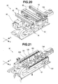
- the second substrate moving unit 15 which feeds the printed circuit board 3 with the electronic component mounted thereon to the unloading unit 13 includes conveyors 42 for transferring the printed circuit board 3, and a moving mechanism 91 which translates the conveyors 42, as shown in Figs. 20 to 25 .
- a conveyor 92 (see Fig. 20 ) which constitutes the downstream or upstream end portion of the unloading unit 13 is attached to the moving mechanism 91 according to this embodiment so as to translate together with the conveyors 42 of the second substrate moving unit 15.
- the conveyors 42 of the second substrate moving unit 15, and the conveyors 92 of the unloading unit 13 are supported by one support plate 93 and connected to the moving mechanism 91 (to be described later) via the support plate 93, as shown in Fig. 20 .
- the conveyors 42 and 92 include belts 94 and 95 extending in a direction parallel to the X-direction.
- the belts 94 and 95 are arranged so as to support the side portions, as the long sides, of the printed circuit board 3, and rotate upon being driven by one driving motor 96.
- the belts 94 of the second substrate moving unit 15 are configured so that the printed circuit board 3 can transfer from the conveyor 17 on the mounting stage side. That is, in the state where the conveyor 17 on the mounting stage side is set at an upper position, the upper surfaces of the belts 72 are almost flush with those of the belts 94 of the second substrate moving unit 15.
- the conveyors 42 of the second substrate moving unit 15 correspond to a "second conveyor" according to the invention defined in claim 4.
- the conveyor 17 on the side of the mounting stage 18 must move the printed circuit board 3 to the side of the second substrate moving unit 15. That is, the second substrate moving unit 15 according to this embodiment is configured using part (conveyor 17) of the substrate holding unit 12.
- the moving mechanism 91 serves to reciprocally move the support plate 93 in a direction parallel to the Y-direction.
- the moving mechanism 91 according to this embodiment includes a pair of guide rails 101 extending in a direction parallel to the Y-direction, and a ball screw mechanism 102 inserted between the guide rails 101, as shown in Fig. 21 .
- the guide rails 101 are formed to extend from the second conveyance lane L2 to the third conveyance lane L3.
- the guide rails 101 correspond to a "guide member" according to the invention defined in claim 4.
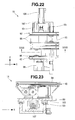
- Sliders 103 are movably attached to the guide rails 101, as shown in Figs. 23 to 25 .
- the support plate 93 is held on the sliders 103.
- the ball screw mechanism 102 includes a ball screw shaft 105 rotated by a motor 104, and a ball screw nut 106 which threadably engages with the ball screw shaft 105.
- the motor 104 and ball screw shaft 105 are supported so as not to move to a support table 107 of the moving mechanism 91.
- the support plate 93 is attached to the ball screw nut 106.
- the support plate 93 and two conveyors 42 and 92 translate between the position of the upstream end in the Y-direction and that of the downstream end in the Y-direction as the ball screw shaft 105 rotates upon being driven by the motor 104.
- the conveyors 42 of the second substrate moving unit 15 are set at the same position in the Y-direction as that of the conveyors 17 on the side of the mounting stage 18, and the conveyors 92 at the two end portions of the unloading unit 13 are set at the same position in the Y-direction as that of the other conveyor 19 of the unloading unit 13, as shown in Fig. 9 .
- the conveyors 42 of the second substrate moving unit 15 are set at the same position in the Y-direction as that of the other conveyor 19 of the unloading unit 13, although not shown.
- the conveyors 92 at the two end portions of the unloading unit 13 provided on the support plate 93 move to the outside (a side opposite to the second conveyance lane L2) of the other conveyor 19 of the unloading unit 13.
- the second substrate moving unit 15 in adopting the above-mentioned first and second embodiments can be configured by placing the mounting stage 18 on the support plate 93 shown in these embodiments.
- the first substrate moving unit 14 can be formed to be relatively compact in the Y-direction, compared to the case wherein the first substrate moving unit 14 is of the stage movement type. This is because the first substrate moving unit of the stage movement type requires an interference avoidance area to avoid interference between the moving stage and the substrate holding unit 12.
- a flexible printed circuit board 3 can be fed to the substrate holding unit 12 quickly and reliably.
- the second substrate moving unit 15 receives the printed circuit board 3 from the substrate holding unit 12 using the conveyors 17 and 42 which support the side portions, as the long sides, of the printed circuit board 3, and translates the conveyors 42 to feed the printed circuit board 3 to the unloading unit 13.
- a film-like printed circuit board 3 is fed from the substrate holding unit 12 to the unloading unit 13 without flexure.
- high-quality component mounting can be done so that an electronic component mounted on the printed circuit board 3 does not move from a mounting position.
- a printed circuit board loaded by the loading unit is moved in the second horizontal direction by the first substrate moving unit and fed to the substrate holding unit. After an electronic component has been mounted on the printed circuit board by the substrate holding unit, it is fed to the unloading unit by the second substrate moving unit and unloaded in the first horizontal direction by the unloading unit.
Landscapes
- Engineering & Computer Science (AREA)
- Manufacturing & Machinery (AREA)
- Microelectronics & Electronic Packaging (AREA)
- Supply And Installment Of Electrical Components (AREA)
Abstract
Description
- The present invention relates to an electronic component mounting apparatus which mounts an electronic component on a printed circuit board.
- A conventional general electronic component mounting apparatus (to be simply referred to as a mounting apparatus hereinafter) includes a conveyance device which horizontally feeds a printed circuit board. Also, in the conventional electronic component mounting apparatus, a printed circuit board loading unit, a substrate holding unit on which a printed circuit board is held at the time of mounting, and a printed circuit board unloading unit are aligned in a line in the conveyance direction of the conveyance device.
- An electronic component mounting apparatus of this type adopts a form shown in, for example, Japanese Patent No.
4278903 literature 1 hereinafter) or Japanese Patent Laid-Open No.2003-163498 literature 2 hereinafter) to obtain a high productivity. -
Literature 1 discloses a mounting system formed by aligning a plurality of mounting apparatuses in a line in the conveyance direction. - The mounting apparatus disclosed in
literature 1 includes two conveyance devices. These conveyance devices serve to divert a mounting apparatus, that has generated a delay in mounting, of a plurality of mounting apparatuses to feed a printed circuit board to the downstream mounting apparatus. These conveyance devices are aligned in one horizontal direction perpendicular to the conveyance direction. Also, distribution conveyors are connected to the upstream and downstream ends of these conveyance devices to allow selection of a conveyance device to which a printed circuit board is conveyed. -
Literature 2 discloses a mounting system formed by aligning a plurality of mounting apparatuses in a line in a horizontal direction perpendicular to the conveyance direction. The conveyance devices for each mounting apparatus disclosed inliterature 2 are connected to each other by a loading conveyor and an unloading conveyor. The unloading conveyor can feed printed circuit boards to the upstream ends of all conveyance devices. The unloading conveyor can receive printed circuit boards from the downstream ends of all conveyance devices. - In a conventional general mounting apparatus in which a printed circuit board loading unit, substrate holding unit, and printed circuit board unloading unit are aligned in a line in the conveyance direction of a printed circuit board conveyance device, there is a limit in shortening its dimension in the conveyance direction.
- In the mounting apparatus described in
literature 1, distribution conveyors must be provided between the plurality of mounting apparatuses, thus increasing its dimension in the conveyance direction. - In the mounting apparatus described in
literature 2, a loading conveyor and an unloading conveyor must be provided on the upstream and downstream sides, respectively, thus increasing its size in the conveyance direction. - The present invention has been made to solve such problems, and has as its object to provide an electronic component mounting apparatus that is compact in the conveyance direction of a conveyance device for conveying a printed circuit board.
- In order to achieve the above-mentioned object, according to the present invention, there is provided an electronic component mounting apparatus comprising a loading unit which moves a printed circuit board in a first horizontal direction to load the printed circuit board, a first substrate moving unit which moves the printed circuit board, loaded by the loading unit, in a second horizontal direction perpendicular to the first horizontal direction, a substrate holding unit which temporarily holds the printed circuit board moved by the first substrate moving unit, a component mounting unit which mounts an electronic component on the printed circuit board held by the substrate holding unit, a second substrate moving unit which moves the printed circuit board with the electronic component mounted thereon in the second horizontal direction, and an unloading unit which moves the printed circuit board, moved by the second substrate moving unit, in the first horizontal direction to unload the printed circuit board.
-
-
Fig. 1 is a plan view showing the arrangement of an electronic component mounting apparatus according to the first embodiment of the present invention; -
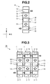
Fig. 2 is a plan view showing the arrangement of a substrate conveyance unit according to the first embodiment of the present invention; -
Fig. 3 is a plan view of a mounting system built using the substrate conveyance unit according to the first embodiment of the present invention; -
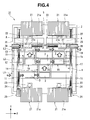
Fig. 4 is a plan view showing the arrangement of an electronic component mounting apparatus according to the second embodiment of the present invention; -
Fig. 5 is a plan view showing the arrangement of a substrate conveyance unit according to the second embodiment of the present invention; -
Fig. 6 is a plan view of a mounting system built using the substrate conveyance unit according to the second embodiment of the present invention; -
Fig. 7 is a plan view showing the arrangement of an electronic component mounting apparatus according to the third embodiment of the present invention; -
Fig. 8 is a plan view showing the arrangement of a substrate conveyance unit according to the third embodiment of the present invention; -
Fig. 9 is a plan view illustrating a practical example of the substrate conveyance unit; -
Fig. 10 is a perspective view illustrating a practical example of the substrate conveyance unit; -
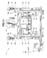
Fig. 11 is a plan view of a first substrate moving unit; -
Fig. 12 is a perspective view of the first substrate moving unit; -
Fig. 13 is a side view of the first substrate moving unit; -
Fig. 14 is a sectional view for explaining the internal structure of the first substrate moving unit, and shows the state where belts are lifted; -
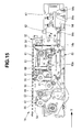
Fig. 15 is a sectional view for explaining the internal structure of the first substrate moving unit, and shows the state where belts are lowered; -
Fig. 16 is a perspective view of a mounting stage; -
Fig. 17 is an exploded perspective view of the mounting stage; -
Fig. 18 is a plan view showing the state where a mounting plate of the mounting stage is removed; -
Fig. 19 is a sectional view taken along a line XIX - XIX inFig. 18 ; -
Fig. 20 is a perspective view of a second substrate moving unit; -
Fig. 21 is a perspective view showing the state where a support plate for the second substrate moving unit is removed; -
Fig. 22 is a plan view of the second substrate moving unit; -
Fig. 23 is a sectional view taken along a line XXIII - XXIII inFig. 22 ; -
Fig. 24 is a side view of the second substrate moving unit; and -
Fig. 25 is a plan view showing the state where a support plate for the second substrate moving unit is removed. - An embodiment of an electronic component mounting apparatus according to the present invention will be described in detail below with reference to
Figs. 1 to 3 . - An electronic
component mounting apparatus 1 shown inFig. 1 is built by placing various devices (to be described later) on onebase 2. Although details will be described later, the various devices include devices that constitute asubstrate conveyance unit 4 which conveys a printedcircuit board 3, and devices that constitute acomponent mounting unit 5 which mounts an electronic component (not shown). - The
substrate conveyance unit 4 has a function of conveying the printedcircuit board 3 on thebase 2 in first and second horizontal directions that are orthogonal to each other, as shown inFigs. 1 and2 . The first horizontal direction is the direction from the left to the right inFigs. 1 and2 , and the second horizontal direction is the direction from the bottom to the top inFigs. 1 and2 . In the following description, the first horizontal direction will be simply referred to as the X-direction, and the second horizontal direction will be simply referred to as the Y-direction. Also, in the following description, the left side will be referred to as the upstream side in the X-direction inFigs. 1 and2 , and the right side will be referred to as the downstream side in the X-direction inFigs. 1 and2 . Moreover, in the following description, the lower side will be referred to as the upstream side in the Y-direction inFigs. 1 and2 , and the upper side will be referred to as the downstream side in the Y-direction inFigs. 1 and2 . - The
substrate conveyance unit 4 includes aloading unit 11,substrate holding unit 12, andunloading unit 13 which are aligned in the Y-direction on thebase 2, and a firstsubstrate moving unit 14 and secondsubstrate moving unit 15 which move theprinted circuit board 3 in the Y-direction between theunits - The
loading unit 11 includes aconveyor 16 for loading the printedcircuit board 3. Theconveyor 16 is disposed at the upstream end in the Y-direction (the lower end inFigs. 1 and2 ) on thebase 2, and traverses thebase 2 in the X-direction. The printedcircuit board 3 is fed from a device in the previous step to the upstream end in the X-direction on theconveyor 16, and fed onto thebase 2 by theconveyor 16. Theconveyor 16 feeds the printedcircuit board 3 in the X-direction on a predetermined substrate movement surface. - The
substrate holding unit 12 includes aconveyor 17 capable of feeding the printedcircuit board 3 in the X-direction, and amounting stage 18 positioned inside theconveyor 17. Themounting stage 18 has a structure which can temporarily hold the printedcircuit board 3 on a predetermined substrate support surface. The printedcircuit board 3 loaded by theloading unit 11 moves onto thesubstrate holding unit 12 by a device that constitutes the first substrate moving unit 14 (to be described later). - The first
substrate moving unit 14 includes a moving member (not shown) which moves in the Y-direction as the printedcircuit board 3 is placed on it. The printedcircuit board 3 placed on the moving member moves from theloading unit 11 to thesubstrate holding unit 12. As the moving member, belts, for example, can be used. The firstsubstrate moving unit 14 has not only a function of moving the moving member in the Y-direction, but also a function of lifting or lowering it. The moving member ascends or descends between a substrate transfer position higher than the substrate movement surface of theloading unit 11 and the substrate support surface of thesubstrate holding unit 12, and a standby position lower than this substrate movement surface and substrate support surface. The substrate transfer position corresponds to a "first position" according to the invention defined inclaim 5, and the standby position corresponds to a "second position" according to the invention defined inclaim 5. - The unloading
unit 13 includes aconveyor 19 which unloads the printedcircuit board 3 in the X-direction from the downstream end in the Y-direction (the upper end inFigs. 1 and2 ) on thebase 2. Theconveyor 19 traverses thebase 2 in the X-direction. The printedcircuit board 3 has an electronic component mounted thereon is released by thesubstrate holding unit 12, and moves to theunloading unit 13 from thesubstrate holding unit 12 by the second substrate moving unit 15 (to be described later). - The second
substrate moving unit 15 includes a guide member (not shown) extending in the Y-direction, and a moving mechanism (not shown). The moving mechanism translates the member (conveyor 17) and mountingstage 18, on which the printedcircuit board 3 is placed by thesubstrate holding unit 12, in the Y-direction together with the printedcircuit board 3. Theconveyor 17 and mountingstage 18 are movably supported by the guide member extending in the Y-direction, and reciprocally move between a mounting position shown inFigs. 1 and2 , and an unloading position (not shown) in theunloading unit 13 upon being driven by the moving mechanism. Theconveyor 17 of thesubstrate holding unit 12 moves into theunloading unit 13 to be connected to theconveyor 19 of theunloading unit 13 so that the printedcircuit board 3 can be fed to theconveyor 19 of theunloading unit 13. - The
component mounting unit 5 mounts an electronic component on the printedcircuit board 3 held to the mountingstage 18 mentioned above. Thecomponent mounting unit 5 includescomponent supply devices 21 placed at the upstream and downstream ends of thebase 2 in the Y-direction, and acomponent moving device 22 which moves an electronic component from thecomponent supply device 21 to the printedcircuit board 3, as shown inFig. 1 . - The
component supply device 21 is built by a large number oftape feeders 21a in this embodiment. Acamera 23 for capturing an image of an electronic component from below is provided between thecomponent supply device 21 and thesubstrate conveyance unit 4. - The
component moving device 22 includes a pair of Y beams 24 extending in the Y-direction on thebase 2, and anX beam 25 bridging the Y beams 24. TheX beam 25 moves in a direction parallel to the Y-direction upon being driven by aY driving device 26. TheX beam 25 is provided with ahead unit 27 movable in a direction parallel to the X-direction. Thehead unit 27 has a plurality ofsuction heads 27a, and moves in a direction parallel to the X-direction upon being driven by anX driving device 28. - The
suction head 27a has a suction nozzle (not shown) at its lower end, and is supported on thehead unit 27 to be liftable and rotatable about a vertical axis. The suction heads 27a move between the twocomponent supply devices 21 and the printedcircuit board 3 held on thesubstrate holding unit 12 as thehead unit 27 moves in the X- and Y-directions. Therefore, the secondsubstrate moving unit 15 is positioned to fall within the range in which an electronic component can be mounted by thecomponent mounting unit 5. - With the electronic
component mounting apparatus 1 configured as described above, the printedcircuit board 3 loaded by theloading unit 11 is moved in the Y-direction by the firstsubstrate moving unit 14, fed to thesubstrate holding unit 12, and held by thesubstrate holding unit 12. After the printedcircuit board 3 is held by thesubstrate holding unit 12, an electronic component is removed from thecomponent supply devices 21 and mounted on the printedcircuit board 3 by thecomponent mounting unit 5. After the end of mounting of the electronic component, the printedcircuit board 3 is fed to theunloading unit 13 by the secondsubstrate moving unit 15 and unloaded in the X-direction by the unloadingunit 13. - Hence, according to this embodiment, since the printed
circuit board 3 is moved in the Y-direction between theloading unit 11 and theunloading unit 13 and placed, an electronic component mounting apparatus compact in the X-direction can be provided. - In this embodiment, the
loading unit 11, firstsubstrate moving unit 14,substrate holding unit 12, secondsubstrate moving unit 15, and unloadingunit 13 are aligned in a line in the Y-direction. Hence, an electronic component mounting apparatus more compact in the X-direction can be provided by adopting this embodiment. - The second
substrate moving unit 15 according to this embodiment includes a moving mechanism which translates the member (conveyor 17), on which the printedcircuit board 3 is placed, together with the printedcircuit board 3 along a guide member extending in the Y-direction. - With this arrangement, a printed
circuit board 3 on which a component has been mounted can be moved in the Y-direction and fed to theunloading unit 13 without being affected by large vibration. Hence, according to this embodiment, when a printedcircuit board 3 with a component mounted thereon moves in the Y-direction, the electronic component does not shift from the position at which it was mounted due to vibration or impact, so an electronic component mounting apparatus capable of high-quality component mounting can be provided. - The first
substrate moving unit 14 according to this embodiment uses a moving member which moves in the Y-direction to feed the printedcircuit board 3 from theloading unit 11 to thesubstrate holding unit 12. The moving member ascends or descends between a substrate transfer position higher than the substrate movement surface of theloading unit 11 and the substrate support surface of thesubstrate holding unit 12, and a standby position lower than this substrate movement surface and substrate support surface. - With this arrangement, while the printed
circuit board 3 is positioned in theloading unit 11, the moving member ascends from the standby position to the substrate transfer position and moves in the Y-direction to feed the printedcircuit board 3 to thesubstrate holding unit 12 at once while avoiding interference between theloading unit 11 and thesubstrate holding unit 12. - Therefore, according to this embodiment, since the printed
circuit board 3 can be quickly fed from theloading unit 11 to thesubstrate holding unit 12, an electronic component mounting apparatus with a higher productivity can be provided. - The second
substrate moving unit 15 according to this embodiment is positioned to fall within the range in which an electronic component can be mounted by thecomponent mounting unit 5. - Hence, according to this embodiment, an electronic component can be mounted on the printed
circuit board 3 by thecomponent mounting unit 5 between thesubstrate holding unit 12 and theunloading unit 13 as well. - An electronic component mounting apparatus according to this modification can be used to build a mounting system, as shown in
Fig. 3 . - A mounting
system 29 shown inFig. 3 is formed by aligning a plurality of (three) electroniccomponent mounting apparatuses 1 in the X-direction. Note thatFig. 3 does not illustrate acomponent mounting unit 5 of each electroniccomponent mounting apparatus 1.Loading units 11 of the electroniccomponent mounting apparatuses 1 are connected to each other so as to feed a printedcircuit board 3 in the X-direction. Also, unloadingunits 13 of the electroniccomponent mounting apparatuses 1 are connected to each other so as to feed a printedcircuit board 3 in the X-direction. - With the mounting
system 29 shown inFig. 3 , the printedcircuit board 3 can be fed to all electroniccomponent mounting apparatuses 1 using theloading unit 11 of each electroniccomponent mounting apparatus 1. Again, with the mountingsystem 29, the printedcircuit board 3 can be unloaded from all electroniccomponent mounting apparatuses 1 using theunloading unit 13 of each electroniccomponent mounting apparatus 1. The printedcircuit board 3 moves in the Y-direction from theloading unit 11 in each electroniccomponent mounting apparatus 1 and is fed to thesubstrate holding unit 12. - Hence, according to this modification, since the printed
circuit board 3 can be fed to a plurality of electroniccomponent mounting apparatuses 1 without requiring a distribution conveyor as described above inliterature - Especially, according to this modification, loading of a printed
circuit board 3, mounting of an electronic component, and unloading of the printedcircuit board 3 can be independently done in each electroniccomponent mounting apparatus 1 without influencing the mounting states of other electroniccomponent mounting apparatuses 1. Hence, according to this modification, a mounting system which not only is compact in the X-direction but also has a high mounting efficiency can be provided. - An embodiment of an electronic component mounting apparatus according to the invention defined in
claim 2 will be described in detail with reference toFigs. 4 to 6 . The same reference numerals as described with reference toFigs. 1 to 3 denote the same or similar members inFigs. 4 to 6 , and a detailed description thereof will be omitted as needed. - A
substrate conveyance unit 4 of an electroniccomponent mounting apparatus 31 shown inFig. 4 can feed a printedcircuit board 3 to the downstream and upstream sides in the X-direction in asubstrate holding unit 12. That is, thesubstrate conveyance unit 4 includes a first conveyance lane (conveyance path) L1 formed by aloading unit 11, a second conveyance lane L2 formed by thesubstrate holding unit 12, and a third conveyance lane L3 formed by anunloading unit 13 so as to be aligned in the Y-direction in this order. - The second conveyance lane L2 (substrate holding unit 12) is built by a moving
direction change conveyor 32 positioned at the center of abase 2 in the X-direction, and aconveyor 17 and mountingstage 18 provided on each side of the movingdirection change conveyor 32. In this embodiment, a "first conveyor" according to the invention defined inclaim 2 is implemented by the movingdirection change conveyor 32. - The moving
direction change conveyor 32 rotates a pair of belts extending parallel to the X-direction to feed the printedcircuit board 3 in a direction parallel to the X-direction. The printedcircuit board 3 is fed from the first conveyance lane (conveyance path) L1 to the second conveyance lane L2 by a firstsubstrate moving unit 14, and then fed to the downstream side in the X-direction (the right side inFigs. 4 and5 ) or the upstream side in the X-direction (the left side inFigs. 4 and5 ) by the movingdirection change conveyor 32. That is, the movingdirection change conveyor 32 changes the conveyance direction of the printedcircuit board 3 fed by the firstsubstrate moving unit 14 to the X-direction or a direction opposite to the X-direction. - The mounting
stage 18 according to this embodiment is equivalent to that shown in the first embodiment, and the printedcircuit board 3 fed by the movingdirection change conveyor 32 andconveyor 17 on the second conveyance lane L2 are temporarily held. - A second
substrate moving unit 15 according to this embodiment is provided on each side of the movingdirection change conveyor 32, and feeds the mountingstage 18 in the Y-direction. - That is, the mounting
stage 18 is reciprocally moved between the second conveyance lane L2 and the third conveyance lane L3 by the secondsubstrate moving unit 15. - The unloading
unit 13 according to this embodiment adopts an arrangement which feeds, in the X-direction, the printedcircuit board 3 fed to the third conveyance lane L3 by one secondsubstrate moving unit 15, and the printedcircuit board 3 fed to the third conveyance lane L3 by the other secondsubstrate moving unit 15. - A
component mounting unit 5 according to this embodiment includes twohead units 27, as shown inFig. 4 . Thehead units 27 are supported byX beams 25 to be movable in the X-direction. TheX beam 25 for each head unit is supported by aY beam 24 to be movable in a direction parallel to the Y-direction.Fig. 4 does not illustrate Y beams which support the adjacent ends of the two X beams 25. The range in which eachhead unit 27 can mount a component includes the secondsubstrate moving unit 15, as indicated by an alternate long and two short dashed line A inFig. 4 . - In the electronic
component mounting apparatus 31 according to this embodiment, the printedcircuit board 3 is fed from the first conveyance lane (conveyance path) L1 (loading unit 11) to the second conveyance lane L2 by the firstsubstrate moving unit 14. The printedcircuit board 3 is fed to one mountingstage 18 or the other mountingstage 18 by the movingdirection change conveyor 32 on the second conveyance lane L2. - Hence, according to this embodiment, since a plurality of mounting
stages 18 are used so as to mount an electronic component on the printedcircuit board 3, an electronic component mounting apparatus with a higher mounting efficiency can be provided. - Also, since the electronic
component mounting apparatus 31 distributes printedcircuit boards 3 to two mountingstages 18 using the movingdirection change conveyor 32, only one firstsubstrate moving unit 14 needs to be used despite the provision of a plurality of mountingstages 18. This makes it possible to keep the manufacturing cost relatively low, compared to a case wherein the firstsubstrate moving unit 14 is provided for each mountingstage 18. - An electronic
component mounting apparatus 31 according to this embodiment can be used to build a mounting system, as shown inFig. 6 . - A mounting
system 33 shown inFig. 6 is built by aligning a plurality of (three) electroniccomponent mounting apparatuses 31 according to the second embodiment in the X-direction. Note thatFig. 6 does not illustrate acomponent mounting unit 5 of each electroniccomponent mounting apparatus 31.Loading units 11 of the electroniccomponent mounting apparatuses 31 are connected to each other so as to feed a printedcircuit board 3 in the X-direction. Also, unloadingunits 13 of the electroniccomponent mounting apparatuses 31 are connected to each other so as to feed a printedcircuit board 3 in the X-direction. - When this embodiment is adopted as well, since the printed
circuit board 3 can be fed to a plurality of electroniccomponent mounting apparatuses 31 without requiring a distribution conveyor as described above inliterature - Also, in this modification as well, loading of a printed
circuit board 3, mounting of an electronic component, and unloading of the printedcircuit board 3 can be independently done in each electroniccomponent mounting apparatus 31 without influencing the mounting states of other electroniccomponent mounting apparatuses 31. Hence, according to this modification as well, a mounting system which not only is compact in the X-direction but also has a high mounting efficiency can be provided. - Two second substrate moving units when two mounting stages are provided can be configured as shown in
Figs. 7 and8 . The same reference numerals as described with reference toFigs. 1 to 6 denote the same or similar members inFigs. 7 and8 , and a detailed description thereof will be omitted as needed. - Two second
substrate moving units 15 of an electroniccomponent mounting apparatus 41 shown inFigs. 7 and8 are provided on the outer side of abase 2 with respect to two mountingstages 18 and at the two ends of a second conveyance lane L2. The mounting stages 18 according to this embodiment are held to thebase 2 so as not to move in either the X- or Y-direction. - In the second
substrate moving unit 15, the mountingstage 18 includesconveyors 42 to which a printedcircuit board 3 is fed fromconveyors 17 positioned inside. The printedcircuit board 3 with an electronic component mounted thereon by the mountingstage 18 is moved into the secondsubstrate moving unit 15 by theconveyors 17 and theconveyors 42 of the secondsubstrate moving unit 15. Theconveyors 42 of the secondsubstrate moving unit 15 are translated by the above-mentioned moving mechanism to reciprocally move between the second conveyance lane L2 and a third conveyance lane L3. - The second
substrate moving unit 15 according to this embodiment is different from those shown in the above-mentioned first and second embodiments, and translates theconveyors 42 instead of translating the mountingstage 18. Hence, according to this embodiment, since the load of the moving mechanism is reduced, the cost can be reduced using a low-output motor for driving the moving mechanism. - The electronic
component mounting apparatus 41 according to this embodiment can be used to build a mounting system (not shown). This mounting system is built by aligning a plurality of electroniccomponent mounting apparatuses 41 in the X-direction, and connecting them to each other so as to transfer the printedcircuit board 3. - The detailed structure of the main part of the electronic
component mounting apparatus 41 according to this embodiment will be described in detail below with reference toFigs. 9 to 25 . Thesubstrate conveyance unit 4 of the electroniccomponent mounting apparatus 41 according to this embodiment can convey a flexible film-like printed circuit board 3 (seeFig. 9 ). The printedcircuit board 3 is formed in a rectangular shape as viewed in a plan view. - A
loading unit 11 andunloading unit 13 of asubstrate conveyance unit 4 according to this embodiment are implemented byconveyors conveyors loading unit 11 andunloading unit 13 are formed to support two side portions, as the long sides, of the printedcircuit board 3 formed in a rectangular shape, and extend from the upstream to downstream ends of thebase 2 in the X-direction. - A pair of
belts 51 of theconveyors Fig. 10 . The belt frames 52 are supported by thebase 2 while being spaced apart from thebase 2 by a predetermined distance upwards. - A first
substrate moving unit 14 is provided at a position corresponding to the center of theloading unit 11 in the longitudinal direction on thebase 2. Also, a movingdirection change conveyor 32 and the mountingstage 18 of asubstrate holding unit 12, and theconveyors 42 of the secondsubstrate moving unit 15 are provided between theloading unit 11 and theunloading unit 13 to build the second conveyance lane L2. - The first
substrate moving unit 14 includes a pair ofpressure receiving members 53 extending in the Y-direction, as shown inFigs. 9 and10 . Thepressure receiving members 53 serve to regulate an upward displacement of the printedcircuit board 3 when the printedcircuit board 3 is fed in the Y-direction by the firstsubstrate moving unit 14. - The
pressure receiving members 53 are spaced apart from each other by a distance corresponding to the length of each long side of the printedcircuit board 3. Thepressure receiving members 53 are positioned above thebelts 51 of theloading unit 11, and held to belt frames 52 of theloading unit 11, and a belt frame 54 (seeFigs. 11 and12 ) of the moving direction change conveyor 32 (to be described later). - The
pressure receiving members 53 are provided with a large number ofrollers 55, as shown inFigs. 11 and12 . - A
conveyor 56 is provided below the pair ofpressure receiving members 53, as shown inFigs. 12 ,14 , and15 . Theconveyor 56 serves to move the printedcircuit board 3 in the Y-direction to feed it from theloading unit 11 to the movingdirection change conveyor 32 of a substrate holding unit 12 (to be described later). - The
conveyor 56 serves to rotate a pair ofbelts 57 so that their upper portions move in the Y-direction. In this embodiment, thebelts 57 correspond to a "moving member" according to the invention defined inclaim 5. - The
belts 57 of theconveyor 56 are driven by one driving motor 58 (seeFigs. 11 and12 ). The upper portions of thebelts 57 divert thebelts 51 of theloading unit 11 downwards to extend in the Y-direction, and are guided downwards on the upstream side, in the Y-direction, of afirst belt 59 of the movingdirection change conveyor 32, as shown inFig. 14 . The movingdirection change conveyor 32 includes thefirst belt 59, and asecond belt 60 positioned upstream of thefirst belt 59 in the Y-direction. Thesecond belt 60 is positioned between the twobelts 57 of the firstsubstrate moving unit 14 to extend in the X-direction. - A plurality of
pulleys 61 which support at least the upper portions of thebelts 57 in theconveyor 56 of the firstsubstrate moving unit 14 are connected to a lift mechanism denoted byreference numeral 62 inFigs. 13 to 15 . Thelift mechanism 62 is implemented by aparallel linkage mechanism 63, and anair cylinder 64 connected to theparallel linkage mechanism 63. Anupper link 63a of theparallel linkage mechanism 63 is connected to a support plate 65 (seeFigs. 11 to 13 ) which supports thepulleys 61. Thesupport plate 65 is movably supported by aframe member 14a of the firstsubstrate moving unit 14. The direction in which thesupport plate 65 moves is regulated only vertically by a guide member 66 (seeFigs. 11 and12 ). Theframe member 14a is held to thebase 2 by a plurality ofattachment brackets 14b (seeFigs. 11 and12 ). - The
air cylinder 64 has its one end supported to be vertically swingable, and its other end supported by asupport bracket 64a through asupport shaft 64b. Thesupport bracket 64a is held to thebase 2. Thesupport shaft 64b extends in a direction parallel to the X-direction, and passes through the trailing end of theair cylinder 64, that is, its end opposite to apiston rod 64c. - The
support plate 65 which supports thepulleys 61 ascends together with theupper link 63a as thepiston rod 64c of theair cylinder 64 extends, as shown inFig. 14 . At this time, theair cylinder 64 swings about thesupport shaft 64b so as to set thepiston rod 64c at a relatively high position. In this state, the twobelts 57 of the firstsubstrate moving unit 14 ascend to a substrate transfer position higher than the substrate movement surface (the upper surface of the belts 51) of theloading unit 11, and the substrate support surface (the upper surfaces of the first andsecond belts 59 and 60) of the movingdirection change conveyor 32. - Also, the
support plate 65 which supports thepulleys 61 descends together with theupper link 63a as thepiston rod 64c retracts, as shown inFig. 15 . At this time, theair cylinder 64 swings about thesupport shaft 64b so as to set thepiston rod 64c at a relatively low position. In this state, thebelts 57 ascend to a substrate transfer position lower than the substrate movement surface of theloading unit 11, and the substrate support surface of the movingdirection change conveyor 32. - The
belts 57 of the firstsubstrate moving unit 14 descend to a standby position when the printedcircuit board 3 is fed in the X-direction by thebelts 51 of theloading unit 11. Thebelts 57 of the firstsubstrate moving unit 14 ascend to a substrate transfer position while the printedcircuit board 3 is fed to a position corresponding to the firstsubstrate moving unit 14 by thebelts 51 of theloading unit 11. With this arrangement, as thebelts 57 ascend to the substrate transfer position, the printedcircuit board 3 moves from theloading unit 11 to the firstsubstrate moving unit 14 upon ascent together with thebelts 57. At this time, the side portions, as short sides, of the printedcircuit board 3 are placed on thebelts 57. - In this ascended state, the upper surface of the printed
circuit board 3 is pressed from below by therollers 55 of thepressure receiving members 53 to regulate a further upward displacement of the printedcircuit board 3. The printedcircuit board 3 is fed in the Y-direction to a position above the movingdirection change conveyor 32, while being clamped by thebelts 57 and therollers 55, as thebelts 57 of the firstsubstrate moving unit 14 rotate. Thebelts 57 of the firstsubstrate moving unit 14 descend to a standby position after the printedcircuit board 3 moves to a position above the movingdirection change conveyor 32. With this arrangement, the printedcircuit board 3 is placed on the first andsecond belts direction change conveyor 32 as thebelts 57 descend. - The first and
second belts direction change conveyor 32 are arranged so as to support the side portions, as the long sides, of the printedcircuit board 3. Also, the first andsecond belts Figs. 11 and12 ). That is, the printedcircuit board 3 placed on the first andsecond belts - The
conveyor 17 and mountingstage 18 are disposed on each side of the movingdirection change conveyor 32. The mountingstage 18 includes a mountingplate 71 inserted in theconveyor 17, as shown inFigs. 16 and17 . Theconveyor 17 serves to feed the printedcircuit board 3 along the second conveyance lane L2, and includes a pair ofbelts 72 extending in a direction parallel to the X-direction. Thebelts 72 are arranged so as to support the side portions, as the long sides, of the printedcircuit board 3, and rotate upon being driven by one drivingmotor 73. - Also, the
conveyor 17 is supported by a bottom plate 74 (seeFig. 17 ) of the mountingstage 18 to be vertically movable. Thebottom plate 74 is held to thebase 2, although not shown. Thebottom plate 74 is provided with alift mechanism 75 for vertically moving theconveyor 17, as shown inFigs. 18 and 19 . Thelift mechanism 75 vertically moves a roller 76 (seeFigs. 17 and19 ), disposed on theconveyor 17, usingcams 77. Thecam 77 has aninclined surface 77a on which theroller 76 rolls, and is disposed on the two side portions of theconveyor 17. Thecams 77 are supported by the two end portions of a support plate 78 (seeFig. 18 ) extending in the Y-direction. - The
support plate 78 is translatably supported by thebottom plate 74 through aguide rail 79 and a slider 80 (seeFig. 19 ). The direction in which thesupport plate 78 moves is parallel to the X-direction. Thesupport plate 78 is connected to anair cylinder 81, and moves to the downstream or upstream side in the X-direction upon being driven by theair cylinder 81. As thesupport plate 78 andcam 77 move to the upstream or downstream side in the X-direction, theroller 76 of theconveyor 17 rolls on theinclined surface 77a, and theconveyor 17 vertically moves. In the state where theconveyor 17 has ascended, the upper surfaces of the belts 72 (the substrate support surface of the substrate holding unit 12) are positioned at the same level as that of the upper surfaces of the first andsecond belts direction change conveyor 32. However, in the state where theconveyor 17 has descended, the upper surfaces of thebelts 72 of theconveyor 17 are positioned at a level lower than that of the upper surface of the mountingplate 71. - The mounting
plate 71 serves to place the printedcircuit board 3 in mounting an electronic component on the printedcircuit board 3, has an upper surface formed flatly, and is held on thebottom plate 74 through a leg member 82 (seeFig. 16 ). Thelift mechanism 75 is disposed between the mountingplate 71 and thebottom plate 74. - A large number of small holes 83 (see
Fig. 17 ) for air suction are formed in the mountingplate 71. Thesmall holes 83 are connected to a suction air passage (not shown) in theplate 71. The suction air passage is connected to an air suction device (not shown). That is, the printedcircuit board 3 is placed on theplate 71 while air is drawn into theplate 71 by suction from thesmall holes 83 to chuck and hold the printedcircuit board 3 on theplate 71. An electronic component is mounted on the printedcircuit board 3 while the printedcircuit board 3 is held on theplate 71 in this way. - The second
substrate moving unit 15 which feeds the printedcircuit board 3 with the electronic component mounted thereon to theunloading unit 13 includesconveyors 42 for transferring the printedcircuit board 3, and a movingmechanism 91 which translates theconveyors 42, as shown inFigs. 20 to 25 . A conveyor 92 (seeFig. 20 ) which constitutes the downstream or upstream end portion of theunloading unit 13 is attached to the movingmechanism 91 according to this embodiment so as to translate together with theconveyors 42 of the secondsubstrate moving unit 15. - The
conveyors 42 of the secondsubstrate moving unit 15, and theconveyors 92 of theunloading unit 13 are supported by onesupport plate 93 and connected to the moving mechanism 91 (to be described later) via thesupport plate 93, as shown inFig. 20 . - The
conveyors belts belts circuit board 3, and rotate upon being driven by one drivingmotor 96. - The
belts 94 of the secondsubstrate moving unit 15 are configured so that the printedcircuit board 3 can transfer from theconveyor 17 on the mounting stage side. That is, in the state where theconveyor 17 on the mounting stage side is set at an upper position, the upper surfaces of thebelts 72 are almost flush with those of thebelts 94 of the secondsubstrate moving unit 15. In this embodiment, theconveyors 42 of the secondsubstrate moving unit 15 correspond to a "second conveyor" according to the invention defined inclaim 4. - To move the printed
circuit board 3 from the side of the mountingstage 18 to the secondsubstrate moving unit 15, theconveyor 17 on the side of the mountingstage 18 must move the printedcircuit board 3 to the side of the secondsubstrate moving unit 15. That is, the secondsubstrate moving unit 15 according to this embodiment is configured using part (conveyor 17) of thesubstrate holding unit 12. - The moving
mechanism 91 serves to reciprocally move thesupport plate 93 in a direction parallel to the Y-direction. The movingmechanism 91 according to this embodiment includes a pair ofguide rails 101 extending in a direction parallel to the Y-direction, and aball screw mechanism 102 inserted between theguide rails 101, as shown inFig. 21 . - The guide rails 101 are formed to extend from the second conveyance lane L2 to the third conveyance lane L3. In this embodiment, the
guide rails 101 correspond to a "guide member" according to the invention defined inclaim 4. -
Sliders 103 are movably attached to theguide rails 101, as shown inFigs. 23 to 25 . Thesupport plate 93 is held on thesliders 103. - The
ball screw mechanism 102 includes aball screw shaft 105 rotated by amotor 104, and aball screw nut 106 which threadably engages with theball screw shaft 105. Themotor 104 and ball screwshaft 105 are supported so as not to move to a support table 107 of the movingmechanism 91. - The
support plate 93 is attached to theball screw nut 106. Thesupport plate 93 and twoconveyors ball screw shaft 105 rotates upon being driven by themotor 104. - In the state where the
support plate 93 has moved to the position of the upstream end in the Y-direction, theconveyors 42 of the secondsubstrate moving unit 15 are set at the same position in the Y-direction as that of theconveyors 17 on the side of the mountingstage 18, and theconveyors 92 at the two end portions of theunloading unit 13 are set at the same position in the Y-direction as that of theother conveyor 19 of theunloading unit 13, as shown inFig. 9 . - In the state where the
support plate 93 has moved to the position of the downstream end in the Y-direction, theconveyors 42 of the secondsubstrate moving unit 15 are set at the same position in the Y-direction as that of theother conveyor 19 of theunloading unit 13, although not shown. At this time, theconveyors 92 at the two end portions of theunloading unit 13 provided on thesupport plate 93 move to the outside (a side opposite to the second conveyance lane L2) of theother conveyor 19 of theunloading unit 13. - Note that the second
substrate moving unit 15 in adopting the above-mentioned first and second embodiments can be configured by placing the mountingstage 18 on thesupport plate 93 shown in these embodiments. - With the
substrate conveyance unit 4 configured as shown inFigs. 9 to 25 , the printedcircuit board 3 of theloading unit 11 is placed on thebelts 57 of the firstsubstrate moving unit 14 and fed from theloading unit 11 to thesubstrate holding unit 12. Hence, according to this embodiment, the firstsubstrate moving unit 14 can be formed to be relatively compact in the Y-direction, compared to the case wherein the firstsubstrate moving unit 14 is of the stage movement type. This is because the first substrate moving unit of the stage movement type requires an interference avoidance area to avoid interference between the moving stage and thesubstrate holding unit 12. - Also, in this embodiment, when the printed
circuit board 3 is fed from theloading unit 11 to thesubstrate holding unit 12, it is clamped by thebelts 57 androllers 55 of the firstsubstance moving unit 14 and reliably follows thebelts 57. Hence, according to this embodiment, a flexible printedcircuit board 3 can be fed to thesubstrate holding unit 12 quickly and reliably. - The second
substrate moving unit 15 according to this embodiment receives the printedcircuit board 3 from thesubstrate holding unit 12 using theconveyors circuit board 3, and translates theconveyors 42 to feed the printedcircuit board 3 to theunloading unit 13. With this arrangement, a film-like printedcircuit board 3 is fed from thesubstrate holding unit 12 to theunloading unit 13 without flexure. Hence, according to this embodiment, high-quality component mounting can be done so that an electronic component mounted on the printedcircuit board 3 does not move from a mounting position. - According to the present invention, a printed circuit board loaded by the loading unit is moved in the second horizontal direction by the first substrate moving unit and fed to the substrate holding unit. After an electronic component has been mounted on the printed circuit board by the substrate holding unit, it is fed to the unloading unit by the second substrate moving unit and unloaded in the first horizontal direction by the unloading unit. With this arrangement, since the printed circuit board moves in the second horizontal direction to mount an electronic component, an electronic component mounting apparatus compact in the first horizontal direction can be provided.
Claims (6)
- An electronic component mounting apparatus characterized by comprising:a loading unit (11) which moves a printed circuit board (3) in a first horizontal direction to load the printed circuit board (3);a first substrate moving unit (14) which moves the printed circuit board (3), loaded by the loading unit (11), in a second horizontal direction perpendicular to the first horizontal direction;a substrate holding unit (12) which temporarily holds the printed circuit board (3) moved by the first substrate moving unit (14);a component mounting unit (5) which mounts an electronic component on the printed circuit board (3) held by the substrate holding unit (12);a second substrate moving unit (15) which moves the printed circuit board (3) with the electronic component mounted thereon in the second horizontal direction; andan unloading unit (13) which moves the printed circuit board (3), moved by the second substrate moving unit (15), in the first horizontal direction to unload the printed circuit board (3).
- An apparatus according to claim 1, wherein the substrate holding unit (12) comprises:a first conveyor (32) which changes a moving direction of the printed circuit board (3), moved by the first substrate moving unit (14), to one of the first horizontal direction and a direction opposite to the first horizontal direction; anda mounting stage (18) which temporarily holds the printed circuit board (3) fed by the first conveyor (32).
- An apparatus according to claim 1 or 2, wherein
the loading unit (11), the first substrate moving unit (14), the substrate holding unit (12), the second substrate moving unit (15), and the unloading unit (13) are arranged in a line along the second horizontal direction. - An apparatus according to any of claims 1 to 3, wherein
the second substrate moving unit (15) comprises:a second conveyor (42) which moves the printed circuit board (3) from the substrate holding unit (12);a guide rail (101) which extends in the second horizontal direction, and supports the second conveyor (42) to be movable in the second horizontal direction; anda moving mechanism (91) which translates the second conveyor (42) along the guide rail (101), together with the printed circuit board (3). - An apparatus according to any of claims 1 to 4, wherein
the first substrate moving unit (14) ascends or descends between a first position higher than a substrate movement surface, along which the printed circuit board (3) moves in the loading unit (11), and a substrate support surface, along which the printed circuit board (3) is held in the substrate holding unit (12), and a second position lower than the substrate movement surface and the substrate support surface, and comprises a moving member (57) which moves in the second horizontal direction to transfer the printed circuit board (3) from the loading unit (11) to the substrate holding unit (12) at the first position. - An apparatus according to any of claims 1 to 5, wherein
the second substrate moving unit (15) is positioned to fall within a range in which an electronic component has been mounted by the component mounting unit (5).
Applications Claiming Priority (1)
| Application Number | Priority Date | Filing Date | Title |
|---|---|---|---|
| JP2013003284A JP6166903B2 (en) | 2013-01-11 | 2013-01-11 | Electronic component mounting equipment |
Publications (3)
| Publication Number | Publication Date |
|---|---|
| EP2755462A2 true EP2755462A2 (en) | 2014-07-16 |
| EP2755462A3 EP2755462A3 (en) | 2016-03-30 |
| EP2755462B1 EP2755462B1 (en) | 2019-06-19 |
Family
ID=49989406
Family Applications (1)
| Application Number | Title | Priority Date | Filing Date |
|---|---|---|---|
| EP13005994.2A Active EP2755462B1 (en) | 2013-01-11 | 2013-12-20 | Electronic component mounting apparatus |
Country Status (4)
| Country | Link |
|---|---|
| US (1) | US9386735B2 (en) |
| EP (1) | EP2755462B1 (en) |
| JP (1) | JP6166903B2 (en) |
| KR (1) | KR101543678B1 (en) |
Cited By (1)
| Publication number | Priority date | Publication date | Assignee | Title |
|---|---|---|---|---|
| CN109890194A (en) * | 2017-12-06 | 2019-06-14 | 松下知识产权经营株式会社 | Component installation system, component mounting apparatus and board carrying method |
Families Citing this family (3)
| Publication number | Priority date | Publication date | Assignee | Title |
|---|---|---|---|---|
| DE112017006747T5 (en) | 2017-01-06 | 2019-09-19 | Yamaha Hatsudoki Kabushiki Kaisha | Mounting target working device |
| DE112017007428B4 (en) * | 2017-01-06 | 2025-09-04 | Yamaha Hatsudoki Kabushiki Kaisha | Assembly target work device |
| CN110773984B (en) * | 2019-11-08 | 2024-10-29 | 中国石油大学胜利学院 | An electric vehicle controller conveying device and an electric vehicle controller clamping spring pressing system |
Citations (2)
| Publication number | Priority date | Publication date | Assignee | Title |
|---|---|---|---|---|
| JP2003163498A (en) | 2001-11-27 | 2003-06-06 | Alps Electric Co Ltd | Mounting method for chip |
| JP4278903B2 (en) | 2002-01-08 | 2009-06-17 | パナソニック株式会社 | Electronic component mounting apparatus and electronic component mounting method |
Family Cites Families (14)
| Publication number | Priority date | Publication date | Assignee | Title |
|---|---|---|---|---|
| JP2540673B2 (en) * | 1991-07-10 | 1996-10-09 | 株式会社テンリュウテクニックス | Tray and electronic component feeder |
| JP3391039B2 (en) * | 1993-02-23 | 2003-03-31 | 松下電器産業株式会社 | Mounting board production system |
| WO2001026440A1 (en) | 1999-05-21 | 2001-04-12 | Matsushita Electric Industrial Co., Ltd. | Device for transferring/holding sheetlike member and its method |
| DE60026728T2 (en) * | 1999-11-05 | 2006-08-24 | Matsushita Electric Industrial Co., Ltd., Kadoma | COMPONENT FIXING DEVICE AND METHOD |
| WO2002017699A1 (en) | 2000-08-22 | 2002-02-28 | Matsushita Electric Industrial Co., Ltd. | Device and method for mounting parts |
| DE60113152T2 (en) * | 2000-12-12 | 2006-03-09 | Matsushita Electric Industrial Co., Ltd., Kadoma | MAGAZINE, COMPONENT FILING FEEDING DEVICE AND COMPONENT MOUNTING DEVICE |
| JP2003078287A (en) | 2001-09-05 | 2003-03-14 | Matsushita Electric Ind Co Ltd | Board transfer method for component mounter and board transfer apparatus |
| US7082680B2 (en) * | 2001-11-21 | 2006-08-01 | Mirae Corporation | Mounting method of electronic components |
| JP4813056B2 (en) * | 2004-07-29 | 2011-11-09 | パナソニック株式会社 | Mounting head for component mounting, and component mounting apparatus provided with the mounting head |
| WO2008001910A1 (en) | 2006-06-29 | 2008-01-03 | Yamaha Motor Co., Ltd. | Surface mounting apparatus |
| JP4582181B2 (en) * | 2008-04-08 | 2010-11-17 | ソニー株式会社 | Component mounting apparatus and manufacturing method of mounted products |
| JP4692687B2 (en) | 2010-07-12 | 2011-06-01 | ソニー株式会社 | Mounting board manufacturing method |
| JP5551625B2 (en) * | 2011-01-13 | 2014-07-16 | 東京エレクトロン株式会社 | Substrate processing apparatus and substrate processing method |
| JP5721469B2 (en) * | 2011-02-28 | 2015-05-20 | 富士機械製造株式会社 | Component mounting method and component mounting apparatus |
-
2013
- 2013-01-11 JP JP2013003284A patent/JP6166903B2/en active Active
- 2013-12-20 EP EP13005994.2A patent/EP2755462B1/en active Active
-
2014
- 2014-01-08 US US14/150,529 patent/US9386735B2/en active Active
- 2014-01-10 KR KR1020140003383A patent/KR101543678B1/en active Active
Patent Citations (2)
| Publication number | Priority date | Publication date | Assignee | Title |
|---|---|---|---|---|
| JP2003163498A (en) | 2001-11-27 | 2003-06-06 | Alps Electric Co Ltd | Mounting method for chip |
| JP4278903B2 (en) | 2002-01-08 | 2009-06-17 | パナソニック株式会社 | Electronic component mounting apparatus and electronic component mounting method |
Cited By (1)
| Publication number | Priority date | Publication date | Assignee | Title |
|---|---|---|---|---|
| CN109890194A (en) * | 2017-12-06 | 2019-06-14 | 松下知识产权经营株式会社 | Component installation system, component mounting apparatus and board carrying method |
Also Published As
| Publication number | Publication date |
|---|---|
| EP2755462A3 (en) | 2016-03-30 |
| US20140196279A1 (en) | 2014-07-17 |
| JP6166903B2 (en) | 2017-07-19 |
| JP2014135416A (en) | 2014-07-24 |
| CN103929941A (en) | 2014-07-16 |
| KR101543678B1 (en) | 2015-08-11 |
| US9386735B2 (en) | 2016-07-05 |
| KR20140091486A (en) | 2014-07-21 |
| EP2755462B1 (en) | 2019-06-19 |
Similar Documents
| Publication | Publication Date | Title |
|---|---|---|
| US8376129B2 (en) | Component mounting apparatus, mounting-component producing method, and conveyor apparatus | |
| US20110041716A1 (en) | Workpiece processing system and method | |
| KR101126501B1 (en) | Device for mounting electronic parts | |
| CN110370803B (en) | A control method for a PCB board inkjet printer and a PCB board inkjet printing production line | |
| EP2755462B1 (en) | Electronic component mounting apparatus | |
| KR100290733B1 (en) | Apparatus for Compensating Flatness of Printed Circuit Board for Surface Mounter | |
| JP6045376B2 (en) | Substrate transfer device and substrate transfer method | |
| JP5879196B2 (en) | Substrate support device | |
| JP4494910B2 (en) | Surface mount equipment | |
| JP4694983B2 (en) | Surface mount machine | |
| CN103193070A (en) | PCB (printed circuit board) transfer system | |
| JP4938599B2 (en) | Surface mount machine | |
| KR102915568B1 (en) | High-speed transfer system for solar cell substrates capable of alignment and maintenance | |
| CN223928789U (en) | Board carrying device and chip huge transfer equipment | |
| JP2005340492A (en) | Surface mount machine | |
| JP4361832B2 (en) | Surface mount machine | |
| CN120390401B (en) | An SMT patch device for PCBA board production | |
| JP2015035457A (en) | Substrate conveyor device | |
| JP4408060B2 (en) | Surface mount machine | |
| JP7133041B2 (en) | Conveyor | |
| JPH07312500A (en) | Printed circuit board transfer method and printed circuit board transfer device | |
| JP6721589B2 (en) | Component mounter | |
| JP2007214429A (en) | Surface mount machine | |
| JP6124922B2 (en) | Substrate transfer device and method for changing substrate transfer device | |
| CN121419143A (en) | A patch device, system and method |
Legal Events
| Date | Code | Title | Description |
|---|---|---|---|
| PUAI | Public reference made under article 153(3) epc to a published international application that has entered the european phase |
Free format text: ORIGINAL CODE: 0009012 |
|
| 17P | Request for examination filed |
Effective date: 20131220 |
|
| AK | Designated contracting states |
Kind code of ref document: A2 Designated state(s): AL AT BE BG CH CY CZ DE DK EE ES FI FR GB GR HR HU IE IS IT LI LT LU LV MC MK MT NL NO PL PT RO RS SE SI SK SM TR |
|
| AX | Request for extension of the european patent |
Extension state: BA ME |
|
| PUAL | Search report despatched |
Free format text: ORIGINAL CODE: 0009013 |
|
| AK | Designated contracting states |
Kind code of ref document: A3 Designated state(s): AL AT BE BG CH CY CZ DE DK EE ES FI FR GB GR HR HU IE IS IT LI LT LU LV MC MK MT NL NO PL PT RO RS SE SI SK SM TR |
|
| AX | Request for extension of the european patent |
Extension state: BA ME |
|
| RIC1 | Information provided on ipc code assigned before grant |
Ipc: H05K 13/00 20060101AFI20160224BHEP Ipc: H05K 13/04 20060101ALI20160224BHEP |
|
| R17P | Request for examination filed (corrected) |
Effective date: 20160929 |
|
| RBV | Designated contracting states (corrected) |
Designated state(s): AL AT BE BG CH CY CZ DE DK EE ES FI FR GB GR HR HU IE IS IT LI LT LU LV MC MK MT NL NO PL PT RO RS SE SI SK SM TR |
|
| STAA | Information on the status of an ep patent application or granted ep patent |
Free format text: STATUS: EXAMINATION IS IN PROGRESS |
|
| 17Q | First examination report despatched |
Effective date: 20171019 |
|
| GRAP | Despatch of communication of intention to grant a patent |
Free format text: ORIGINAL CODE: EPIDOSNIGR1 |
|
| STAA | Information on the status of an ep patent application or granted ep patent |
Free format text: STATUS: GRANT OF PATENT IS INTENDED |
|
| INTG | Intention to grant announced |
Effective date: 20190115 |
|
| GRAS | Grant fee paid |
Free format text: ORIGINAL CODE: EPIDOSNIGR3 |
|
| GRAA | (expected) grant |
Free format text: ORIGINAL CODE: 0009210 |
|
| STAA | Information on the status of an ep patent application or granted ep patent |
Free format text: STATUS: THE PATENT HAS BEEN GRANTED |
|
| RAP1 | Party data changed (applicant data changed or rights of an application transferred) |
Owner name: YAMAHA HATSUDOKI KABUSHIKI KAISHA |
|
| AK | Designated contracting states |
Kind code of ref document: B1 Designated state(s): AL AT BE BG CH CY CZ DE DK EE ES FI FR GB GR HR HU IE IS IT LI LT LU LV MC MK MT NL NO PL PT RO RS SE SI SK SM TR |
|
| REG | Reference to a national code |
Ref country code: GB Ref legal event code: FG4D |
|
| REG | Reference to a national code |
Ref country code: CH Ref legal event code: EP |
|
| REG | Reference to a national code |
Ref country code: IE Ref legal event code: FG4D |
|
| REG | Reference to a national code |
Ref country code: DE Ref legal event code: R096 Ref document number: 602013056702 Country of ref document: DE |
|
| REG | Reference to a national code |
Ref country code: AT Ref legal event code: REF Ref document number: 1147204 Country of ref document: AT Kind code of ref document: T Effective date: 20190715 |
|
| REG | Reference to a national code |
Ref country code: NL Ref legal event code: MP Effective date: 20190619 |
|
| PG25 | Lapsed in a contracting state [announced via postgrant information from national office to epo] |
Ref country code: HR Free format text: LAPSE BECAUSE OF FAILURE TO SUBMIT A TRANSLATION OF THE DESCRIPTION OR TO PAY THE FEE WITHIN THE PRESCRIBED TIME-LIMIT Effective date: 20190619 Ref country code: AL Free format text: LAPSE BECAUSE OF FAILURE TO SUBMIT A TRANSLATION OF THE DESCRIPTION OR TO PAY THE FEE WITHIN THE PRESCRIBED TIME-LIMIT Effective date: 20190619 Ref country code: SE Free format text: LAPSE BECAUSE OF FAILURE TO SUBMIT A TRANSLATION OF THE DESCRIPTION OR TO PAY THE FEE WITHIN THE PRESCRIBED TIME-LIMIT Effective date: 20190619 Ref country code: NO Free format text: LAPSE BECAUSE OF FAILURE TO SUBMIT A TRANSLATION OF THE DESCRIPTION OR TO PAY THE FEE WITHIN THE PRESCRIBED TIME-LIMIT Effective date: 20190919 Ref country code: FI Free format text: LAPSE BECAUSE OF FAILURE TO SUBMIT A TRANSLATION OF THE DESCRIPTION OR TO PAY THE FEE WITHIN THE PRESCRIBED TIME-LIMIT Effective date: 20190619 Ref country code: LT Free format text: LAPSE BECAUSE OF FAILURE TO SUBMIT A TRANSLATION OF THE DESCRIPTION OR TO PAY THE FEE WITHIN THE PRESCRIBED TIME-LIMIT Effective date: 20190619 |
|
| REG | Reference to a national code |
Ref country code: LT Ref legal event code: MG4D |
|
| PG25 | Lapsed in a contracting state [announced via postgrant information from national office to epo] |
Ref country code: RS Free format text: LAPSE BECAUSE OF FAILURE TO SUBMIT A TRANSLATION OF THE DESCRIPTION OR TO PAY THE FEE WITHIN THE PRESCRIBED TIME-LIMIT Effective date: 20190619 Ref country code: BG Free format text: LAPSE BECAUSE OF FAILURE TO SUBMIT A TRANSLATION OF THE DESCRIPTION OR TO PAY THE FEE WITHIN THE PRESCRIBED TIME-LIMIT Effective date: 20190919 Ref country code: GR Free format text: LAPSE BECAUSE OF FAILURE TO SUBMIT A TRANSLATION OF THE DESCRIPTION OR TO PAY THE FEE WITHIN THE PRESCRIBED TIME-LIMIT Effective date: 20190920 Ref country code: LV Free format text: LAPSE BECAUSE OF FAILURE TO SUBMIT A TRANSLATION OF THE DESCRIPTION OR TO PAY THE FEE WITHIN THE PRESCRIBED TIME-LIMIT Effective date: 20190619 |
|
| REG | Reference to a national code |
Ref country code: AT Ref legal event code: MK05 Ref document number: 1147204 Country of ref document: AT Kind code of ref document: T Effective date: 20190619 |
|
| PG25 | Lapsed in a contracting state [announced via postgrant information from national office to epo] |
Ref country code: NL Free format text: LAPSE BECAUSE OF FAILURE TO SUBMIT A TRANSLATION OF THE DESCRIPTION OR TO PAY THE FEE WITHIN THE PRESCRIBED TIME-LIMIT Effective date: 20190619 Ref country code: AT Free format text: LAPSE BECAUSE OF FAILURE TO SUBMIT A TRANSLATION OF THE DESCRIPTION OR TO PAY THE FEE WITHIN THE PRESCRIBED TIME-LIMIT Effective date: 20190619 Ref country code: EE Free format text: LAPSE BECAUSE OF FAILURE TO SUBMIT A TRANSLATION OF THE DESCRIPTION OR TO PAY THE FEE WITHIN THE PRESCRIBED TIME-LIMIT Effective date: 20190619 Ref country code: PT Free format text: LAPSE BECAUSE OF FAILURE TO SUBMIT A TRANSLATION OF THE DESCRIPTION OR TO PAY THE FEE WITHIN THE PRESCRIBED TIME-LIMIT Effective date: 20191021 Ref country code: SK Free format text: LAPSE BECAUSE OF FAILURE TO SUBMIT A TRANSLATION OF THE DESCRIPTION OR TO PAY THE FEE WITHIN THE PRESCRIBED TIME-LIMIT Effective date: 20190619 Ref country code: RO Free format text: LAPSE BECAUSE OF FAILURE TO SUBMIT A TRANSLATION OF THE DESCRIPTION OR TO PAY THE FEE WITHIN THE PRESCRIBED TIME-LIMIT Effective date: 20190619 Ref country code: CZ Free format text: LAPSE BECAUSE OF FAILURE TO SUBMIT A TRANSLATION OF THE DESCRIPTION OR TO PAY THE FEE WITHIN THE PRESCRIBED TIME-LIMIT Effective date: 20190619 |
|
| PG25 | Lapsed in a contracting state [announced via postgrant information from national office to epo] |
Ref country code: IS Free format text: LAPSE BECAUSE OF FAILURE TO SUBMIT A TRANSLATION OF THE DESCRIPTION OR TO PAY THE FEE WITHIN THE PRESCRIBED TIME-LIMIT Effective date: 20191019 Ref country code: ES Free format text: LAPSE BECAUSE OF FAILURE TO SUBMIT A TRANSLATION OF THE DESCRIPTION OR TO PAY THE FEE WITHIN THE PRESCRIBED TIME-LIMIT Effective date: 20190619 Ref country code: IT Free format text: LAPSE BECAUSE OF FAILURE TO SUBMIT A TRANSLATION OF THE DESCRIPTION OR TO PAY THE FEE WITHIN THE PRESCRIBED TIME-LIMIT Effective date: 20190619 Ref country code: SM Free format text: LAPSE BECAUSE OF FAILURE TO SUBMIT A TRANSLATION OF THE DESCRIPTION OR TO PAY THE FEE WITHIN THE PRESCRIBED TIME-LIMIT Effective date: 20190619 |
|
| PG25 | Lapsed in a contracting state [announced via postgrant information from national office to epo] |
Ref country code: TR Free format text: LAPSE BECAUSE OF FAILURE TO SUBMIT A TRANSLATION OF THE DESCRIPTION OR TO PAY THE FEE WITHIN THE PRESCRIBED TIME-LIMIT Effective date: 20190619 |
|
| PG25 | Lapsed in a contracting state [announced via postgrant information from national office to epo] |
Ref country code: PL Free format text: LAPSE BECAUSE OF FAILURE TO SUBMIT A TRANSLATION OF THE DESCRIPTION OR TO PAY THE FEE WITHIN THE PRESCRIBED TIME-LIMIT Effective date: 20190619 Ref country code: DK Free format text: LAPSE BECAUSE OF FAILURE TO SUBMIT A TRANSLATION OF THE DESCRIPTION OR TO PAY THE FEE WITHIN THE PRESCRIBED TIME-LIMIT Effective date: 20190619 |
|
| PG25 | Lapsed in a contracting state [announced via postgrant information from national office to epo] |
Ref country code: IS Free format text: LAPSE BECAUSE OF FAILURE TO SUBMIT A TRANSLATION OF THE DESCRIPTION OR TO PAY THE FEE WITHIN THE PRESCRIBED TIME-LIMIT Effective date: 20200224 |
|
| REG | Reference to a national code |
Ref country code: DE Ref legal event code: R097 Ref document number: 602013056702 Country of ref document: DE |
|
| PLBE | No opposition filed within time limit |
Free format text: ORIGINAL CODE: 0009261 |
|
| STAA | Information on the status of an ep patent application or granted ep patent |
Free format text: STATUS: NO OPPOSITION FILED WITHIN TIME LIMIT |
|
| PG2D | Information on lapse in contracting state deleted |
Ref country code: IS |
|
| REG | Reference to a national code |
Ref country code: CH Ref legal event code: PL |
|
| 26N | No opposition filed |
Effective date: 20200603 |
|
| REG | Reference to a national code |
Ref country code: BE Ref legal event code: MM Effective date: 20191231 |
|
| PG25 | Lapsed in a contracting state [announced via postgrant information from national office to epo] |
Ref country code: MC Free format text: LAPSE BECAUSE OF FAILURE TO SUBMIT A TRANSLATION OF THE DESCRIPTION OR TO PAY THE FEE WITHIN THE PRESCRIBED TIME-LIMIT Effective date: 20190619 Ref country code: SI Free format text: LAPSE BECAUSE OF FAILURE TO SUBMIT A TRANSLATION OF THE DESCRIPTION OR TO PAY THE FEE WITHIN THE PRESCRIBED TIME-LIMIT Effective date: 20190619 |
|
| GBPC | Gb: european patent ceased through non-payment of renewal fee |
Effective date: 20191220 |
|
| PG25 | Lapsed in a contracting state [announced via postgrant information from national office to epo] |
Ref country code: GB Free format text: LAPSE BECAUSE OF NON-PAYMENT OF DUE FEES Effective date: 20191220 Ref country code: FR Free format text: LAPSE BECAUSE OF NON-PAYMENT OF DUE FEES Effective date: 20191231 Ref country code: IE Free format text: LAPSE BECAUSE OF NON-PAYMENT OF DUE FEES Effective date: 20191220 Ref country code: LU Free format text: LAPSE BECAUSE OF NON-PAYMENT OF DUE FEES Effective date: 20191220 |
|
| PG25 | Lapsed in a contracting state [announced via postgrant information from national office to epo] |
Ref country code: LI Free format text: LAPSE BECAUSE OF NON-PAYMENT OF DUE FEES Effective date: 20191231 Ref country code: CH Free format text: LAPSE BECAUSE OF NON-PAYMENT OF DUE FEES Effective date: 20191231 Ref country code: BE Free format text: LAPSE BECAUSE OF NON-PAYMENT OF DUE FEES Effective date: 20191231 |
|
| PG25 | Lapsed in a contracting state [announced via postgrant information from national office to epo] |
Ref country code: CY Free format text: LAPSE BECAUSE OF FAILURE TO SUBMIT A TRANSLATION OF THE DESCRIPTION OR TO PAY THE FEE WITHIN THE PRESCRIBED TIME-LIMIT Effective date: 20190619 |
|
| PG25 | Lapsed in a contracting state [announced via postgrant information from national office to epo] |
Ref country code: MT Free format text: LAPSE BECAUSE OF FAILURE TO SUBMIT A TRANSLATION OF THE DESCRIPTION OR TO PAY THE FEE WITHIN THE PRESCRIBED TIME-LIMIT Effective date: 20190619 Ref country code: HU Free format text: LAPSE BECAUSE OF FAILURE TO SUBMIT A TRANSLATION OF THE DESCRIPTION OR TO PAY THE FEE WITHIN THE PRESCRIBED TIME-LIMIT; INVALID AB INITIO Effective date: 20131220 |
|
| PG25 | Lapsed in a contracting state [announced via postgrant information from national office to epo] |
Ref country code: MK Free format text: LAPSE BECAUSE OF FAILURE TO SUBMIT A TRANSLATION OF THE DESCRIPTION OR TO PAY THE FEE WITHIN THE PRESCRIBED TIME-LIMIT Effective date: 20190619 |
|
| PGFP | Annual fee paid to national office [announced via postgrant information from national office to epo] |
Ref country code: DE Payment date: 20251211 Year of fee payment: 13 |