EP2755431A2 - Mobile Geolokalisierung - Google Patents
Mobile Geolokalisierung Download PDFInfo
- Publication number
- EP2755431A2 EP2755431A2 EP13197797.7A EP13197797A EP2755431A2 EP 2755431 A2 EP2755431 A2 EP 2755431A2 EP 13197797 A EP13197797 A EP 13197797A EP 2755431 A2 EP2755431 A2 EP 2755431A2
- Authority
- EP
- European Patent Office
- Prior art keywords
- signature
- database
- signatures
- timestamp
- information
- Prior art date
- Legal status (The legal status is an assumption and is not a legal conclusion. Google has not performed a legal analysis and makes no representation as to the accuracy of the status listed.)
- Granted
Links
Images



Classifications
-
- H—ELECTRICITY
- H04—ELECTRIC COMMUNICATION TECHNIQUE
- H04W—WIRELESS COMMUNICATION NETWORKS
- H04W64/00—Locating users or terminals or network equipment for network management purposes, e.g. mobility management
- H04W64/006—Locating users or terminals or network equipment for network management purposes, e.g. mobility management with additional information processing, e.g. for direction or speed determination
-
- H—ELECTRICITY
- H04—ELECTRIC COMMUNICATION TECHNIQUE
- H04W—WIRELESS COMMUNICATION NETWORKS
- H04W56/00—Synchronisation arrangements
- H04W56/001—Synchronization between nodes
-
- G—PHYSICS
- G01—MEASURING; TESTING
- G01S—RADIO DIRECTION-FINDING; RADIO NAVIGATION; DETERMINING DISTANCE OR VELOCITY BY USE OF RADIO WAVES; LOCATING OR PRESENCE-DETECTING BY USE OF THE REFLECTION OR RERADIATION OF RADIO WAVES; ANALOGOUS ARRANGEMENTS USING OTHER WAVES
- G01S5/00—Position-fixing by co-ordinating two or more direction or position line determinations; Position-fixing by co-ordinating two or more distance determinations
- G01S5/02—Position-fixing by co-ordinating two or more direction or position line determinations; Position-fixing by co-ordinating two or more distance determinations using radio waves
- G01S5/0252—Radio frequency fingerprinting
- G01S5/02521—Radio frequency fingerprinting using a radio-map
- G01S5/02524—Creating or updating the radio-map
- G01S5/02525—Gathering the radio frequency fingerprints
- G01S5/02526—Gathering the radio frequency fingerprints using non-dedicated equipment, e.g. user equipment or crowd-sourcing
-
- H—ELECTRICITY
- H04—ELECTRIC COMMUNICATION TECHNIQUE
- H04W—WIRELESS COMMUNICATION NETWORKS
- H04W64/00—Locating users or terminals or network equipment for network management purposes, e.g. mobility management
Definitions
- the invention relates to a system and method for generating reference signatures for use in geolocation in a mobile communication system.
- Wireless communication systems such as GSM and the 3 rd Generation (3G) of mobile telephone standards and technology
- GSM Global System for Mobile communications
- 3G 3 rd Generation
- 3GPPTM 3 rd Generation Partnership Project
- the 'phone' may be a smart phone, or another mobile or portable communication unit that is linked wirelessly to a network through which calls are connected. Henceforth all these devices will be referred to as mobile communication units.
- 'Calls' may be data, video, or voice calls, or a combination of these.
- An increasing proportion of communications involve data rather than voice, and are technically referred to as being a 'connection', rather than a 'call'.
- Macro cells utilise high power base stations to communicate with wireless communication units within a relatively large geographical coverage area.
- the coverage area may be several square kilometres, or larger if it is not in a built-up area.
- a wireless communication system typically comprises a plurality of Radio Network Subsystems.
- Each Radio Network Subsystem comprises one or more cells, to which mobile communication units may attach, and thereby connect to the network.
- a base station may serve a cell with multiple antennas, each of which serves one sector of the cell.
- a cellular wireless communication system is described as comprising two parts: the network; and the mobile communication units.
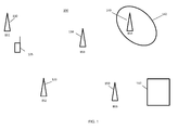
- FIG. 1 provides a perspective view of one prior art wireless communication system 100.
- the system of FIG. 1 comprises a network of base stations, comprising BS1 with reference 110, BS2 with reference 120, BS3 with reference 130, BS4 with reference 140 and BS5 with reference 150. Only one mobile communication unit 105 is shown. In a real network, there may be anywhere from thousands to millions of mobile communication units.
- a base station such as base station 110 communicates with mobile communication unit 105.
- Base station 110 allows mobile communication unit 105 to place calls through the network, and receive calls routed through the network to base station 110.
- Base station 140 has been shown as having a coverage area 142. If base station 140 had an omnidirectional antenna, and the terrain were flat, then coverage area 142 might be circular. However, both the shape and extent of the coverage areas of a typical base station depend on many variables, and may change with time.
- Controller 160 manages calls within the wireless communication system 100. Controller 160 would be linked to all the base stations BS1-BS5, but the links are not shown in order to keep FIG. 1 simple to interpret. Controller 160 may process and store call information from the base stations shown in FIG. 1 , plus many other base stations not shown in FIG. 1 . In a UMTS network, controller 160 may be linked to the base stations via one or more Radio Network Subsystems.
- US patent application number 13/311132 indicates that differential power levels can be used to geo-locate a mobile unit.
- a mobile communication unit provides a measurement of the difference in signal strengths that it receives from at least two base stations.
- the difference value can be compared to one or more contours of constant power difference, for signals received by subscriber mobile communication units in the system. An estimate of location can be obtained from this comparison.
- differential power techniques can be limited in scenarios where there are few pilot signals to make use of.
- Patent application WO2010/083943A shows a further technique, which uses signal strength and timing data derived from the mobile communication unit itself, along with network configuration data provided by the network operator, to locate the mobile communication unit.
- US patent application number 13/369591 indicates that a database of 'known' signatures can be used to aid in locating a mobile communication unit operating in a mobile communication system.
- Each known signature comprises a location measurement or estimate, together with radio frequency and other measurements that were obtained by a mobile communication unit at that location at a particular time. Examples of the 'other measurements' that may be obtained by a mobile communication unit are: control information; a set of cells observable by the first mobile communication unit; and received power level information, for signals received from the observable cells.
- this database of known signatures enables position estimates to be derived, at least for any mobile communication devices that report similar values of the radio frequency and other measurements to those of a known signature. When a 'match' of such similar values is found, the mobile communication device concerned can therefore be assumed to be at the location at which the known signature was recorded.
- US patent application number 13/369591 also employs 'context information'.
- Context information links successive known signatures in the database. When two or more signatures are received from a mobile communication device whose location is unknown, those signatures can be correlated against two or more signatures in the database that are linked by context information.
- US patent application number 13/369591 only allows the estimation of the position of a mobile communication device if there is a match between a known signature in the database and the values of the radio frequency and other measurements reported by that mobile communication device.
- This approach therefore relies on the database having many known signatures.
- the database may require hundreds of thousands or millions of known signatures. Obtaining these known signatures may be difficult.
- One approach is to collect signatures having location information by employing 'drive testing' and/or 'indoor-walk-testing'. Such testing relies on moving a test mobile communications device through a network, in order to collect accurate position measurements from the mobile communication device and at the same time measure, for those positions, the values of radio frequency and other measurements.
- Signatures obtained from drive- or walk- testing can be augmented by selecting data from the Operation Support System (OSS) of the mobile communication system.
- OSS Operation Support System
- the OSS holds measurements made by many or all of the subscriber mobile communication units that operate in a mobile communication system. Some or all of the calls made during drive- or walk- testing will result in a record being created in the OSS.
- the record of the call from the test mobile communications device and the corresponding record from the OSS both contain identification information for the test mobile communications device. If this is the case, then the common identification information can be used. If the correct individual record can be retrieved from the OSS by matching its identification information with the identification information for the test mobile communications device used in the drive or walk testing, then the records can be combined.
- the record retrieved from the OSS may contain measurements made by the mobile communication system that can be added to the record of the same call that was made by the test mobile communications device itself as part of drive or walk testing.
- the identification information in both records allows the two records to be identified as being from the same mobile communication device. This may in turn then allow the two records to be synthesised into a more comprehensive signature than was obtained directly from the test mobile communications device.
- a cellular wireless communication system and a method of generating reference signatures for use in geolocation in a cellular wireless communication system are provided.
- the cellular wireless communication system may, for example, operate in accordance with the GSM, UMTS or LTE standards.
- a method of generating reference signatures for use in geolocation in a cellular wireless communication system comprises obtaining a first signature for a mobile communication unit, the first signature comprising location information, a timestamp and radio frequency measurements obtained by the mobile communication unit at the location, but not containing identification information for the mobile communication unit.
- the first signature is compared to signatures in a database, to identify a second signature of the plurality of signatures, the second signature having a timestamp and radio frequency measurement information that correspond to those of the first signature.
- a first reference signature is created by combining at least a part of the first signature with at least a part of the second signature.
- Creating the first reference signature may further comprise combining the location information of the first signature with at least a part of the second signature.
- the location information of the first signature may be added into the database holding the second signature.
- the database holding the second signature may be the OSS database of a UMTS network.
- a reference signature may be created that has:
- Repetition of the comparison and combination steps for many 'first signatures' creates a database of reference signatures. Those reference signatures may then be used to provide geolocation estimates for other received call signatures. By repeating the method of the invention, therefore, it is possible to enrich the signatures in the database. The resulting set of reference signatures in the database is then available for matching to a variety of other signatures, which do not contain a location measurement from the mobile communication unit that created the signature. These signatures may be received, after creation of the enriched database of signals, from mobile communication units whose current location is unknown but needed.
- the second signature may comprise a user identifier, and at least one of the following types of control information not included in the first signature: timing advance; burst throughput rate; dynamic rate control comprising at least channel quality indicators; signal-to-noise ratio.
- the first signature will typically have some radio frequency measurements. However, these measurements may cover fewer variables than are usually available for signatures in the OSS database of a UMTS network.
- the radio frequency measurements comprised in the first signature may comprise at least one selected from: signal quality; a cell identifier and corresponding observed power level. There may be more than one observed power level available, each for a corresponding cell.
- the first signature may be taken from an anonymized call database.
- Such a database may contain large numbers of signatures, each with a location estimate.
- the signatures in the anonymized call database have been recorded without any identification of either the user or the mobile communication unit that made the call to which the signature relates.
- An example of an anonymized call database is a database compiled in accordance with the Minimization of Drive Test 3GPP standard. The 3GPP Minimisation of Drive Test standard is explained in standards documents 3GPP TS 37.320 and TS 32.422.
- Anonymized call databases have hitherto been only of limited use. Such anonymised databases are 'rich' in location information about where a mobile communication unit was located when it made a call. However, they can be considered to be limited databases in the sense that they typically both:
- the present invention links a 'first' signature from such an anonymised call database with another record of the same call by the same mobile communication unit, the other record being the second signature referred to above.
- the first signature has no identification information, it has sufficient information to enable the corresponding second signature to be identified as a 'match'.
- the second signature is in effect being identified and selected from among very many potential candidates in the database.
- the first signature may comprise a timestamp and a cell identifier.
- the precision of the timestamp recording typically in milliseconds
- the uniqueness of the reported cells typically using global cell identifiers
- the first signature comprises a timestamp and an observed power level
- the precision of the timestamp and the precision of the RF measurement typically in deciBels relative to a milliwatt, or dBm
- dBm deciBels relative to a milliwatt
- a cell may serve hundreds, thousands or even tens of thousands of mobile communication units.
- the invention may comprise, for each of those cells, matching: (i) the timestamps of first and second signatures; (ii) information about multiple cells that could be observed; and (iii) either signal strengths or signal quality.
- the type of information contained in a location-rich, information-poor database is often infrequently available, so the anonymised database is relatively sparsely populated. For example, there may only be entries for calls that occurred under certain RF-related handoff trigger conditions.
- the entries in the location-rich, information-poor anonymised database are created generally much less often than non-RF control data would be provided for calls. So only a subset of all calls will result in a signature being created in the anonymised database.
- databases such as the OSS database of a UMTS system can be considered to be 'information-rich, but location poor', at least relative to the anonymised database.
- the OSS database may capture measurement and control events for every call. So, typically, entries are created in the OSS database much more often than entries in the anonymised database.
- the method of the invention When the method of the invention is repeated, it may be possible to create a link between many, or possibly all, entries in the anonymised database and the corresponding signatures for the same calls in the 'information-rich, but location poor' database. Effectively, the two databases are being combined, to provide many new reference signatures.
- the database of 'second' signatures can be augmented, by the addition of location information for each second signature, for which it has been possible to create a link to the corresponding first signature. This approach allows the construction of inexpensive, complex reference signatures through the linking of information in location-rich and information-rich databases. Those reference signatures can then be used for geolocation of other calls.
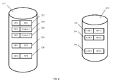
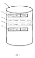
- FIG. 2 provides an exemplary illustration of two databases.
- first database 210 comprises signatures 212, 214, 216, 218, 220.
- First database 210 may, for example, be the OSS database of a UMTS communications system. In a real UMTS communications system, first database 210 may comprise millions of entries, for even a 24 hour period in which calls or data connections are made in the mobile communications network.
- the identification field is the first part of each signature in first database 210.
- the identification field may, for example, comprise the International Mobile Subscriber Identity (IMSI) number of the mobile communication unit concerned.
- IMSI International Mobile Subscriber Identity
- Each of signatures 212, 214, 216, 218 represents information from the same mobile communication unit SU1, but at successively later time points.
- the identification field contains the same entry SU1, as each signature is for the same mobile communication unit SU1.
- Signatures 212, 214, 216, 218 also comprises one or more further fields.
- Signatures 212 and 218 each include a second field, which contains RF measurements.
- Signature 212 has RF measurement RF1
- signature 218 has RF measurement RF3.
- Those measurements may typically include many of the following: timing advance; burst throughput rate; data throughput rate; dynamic rate control, comprising at least channel quality indicators; signal-to-noise ratio; a timestamp; a cell identifier; and an observed power level.
- Signature 218 might typically have been obtained somewhere in the range of 1-100 seconds after signature 212.
- Signatures 214 and 216 were obtained after signature 212 but before signature 218. Each of signatures 214 and 216 includes a second field, which contains control information. Signature 214 has control information denoted as 'Control 1'. Signature 216 has control information denoted as 'Control 2'. However, signatures 214 and 216 do not include the detailed RF measurements that are included in signatures 212 and 218. Each of signatures 214 and 216 includes a timestamp.
- Signature 220 is an example of one signature for a different mobile communication unit, SU2. So signature 220 has entry SU2 in its identification field. Signature 220 also includes RF measurement RF4. Signature 220 will not be considered in detail in relation to FIG. 2 , and is provided to illustrate that the first database 210 has signatures for various different mobile communication units.
- Mobile communication unit SU1 when in communication with the cellular network, will report various RF and control data in the life of a data connection or voice call. It is these report parameters that lead to the signatures 212, 214, 216, 218, which may all arise during one single call/connection involving SU1. Similarly, mobile communication unit SU2 will report various RF and control data in the life of one of its data connections or voice calls, which results in signature 220 and possibly several or many others, not shown.
- OSS Operations Support System
- first database 210 may simply be the OSS database of a cellular network, or may alternatively be a dedicated/bespoke database.
- Second database 230 is a location rich database, which is relatively poor in the information that it holds. Each signature in second database 230 does contain a location measurement. Each signature in second database 230 may contain a different and/or more limited set of RF measurements, than the RF measurements that form part of signatures 212, 218 and 220 in first database 210. Also, each signature in second database 230 does not contain information about the identity of the mobile communication unit that made the call, so second database 230 is an anonymised database.
- Mobile communication unit SU1 may make many data connections and voice calls, each giving rise to a different set of signatures such as 212, 214, 216, 218 in first database 210. For one or more of these calls, mobile communication unit SU1 may also provide a report that is included in a second database 230. In the example shown in FIG. 2 , there are three signatures in second database 230. Signatures 232 and 236 have both been recorded for mobile communication unit SU1. Signature 232 was recorded before signature 236. Both signatures 232 and 236 comprise a location estimate for mobile communication unit SU1.
- Signature 232 contains location estimate LOC1, and RF information RF1A.
- Signature 232 is a record of measurements of the same call by mobile communication unit SU1 as signature 212 in first database 210, with both signatures 232 and 212 being made at the same timepoint. Thus at least some parts of the RF information RF1A contained in signature 232 will correspond closely to at least some parts of RF information RF1 in signature 212.
- Signature 236 contains location estimate LOC3, and RF information RF3A.
- Signature 236 is a record of measurements for the same call by mobile communication unit SU1 as signature 218 in first database 210, with both signatures 236 and 218 being made at the same timepoint. Thus at least some parts of the RF information RF3A contained in signature 236 will correspond closely to at least some parts of information RF3 in signature 218.
- a signature 234 is also recorded in second database 230, but relates to a third mobile communication unit SU3. Signature 234 was recorded after signature 232, but before signature 236. Signature 234 is included in this example only to show that second database 230 contains other signatures, from other mobile communication units than mobile communication unit SU1. Signature 234 contains location estimate LOC2 and RF information RF2A. Somewhere in first database 210 there may be one or more signatures, which are not shown on FIG. 2 , which can be linked to signature 234.
- Signatures 232, 234 and 236 in second database 230 may be recorded if, for example, mobile communication units are selected to contribute anonymously to a limited RF database.
- the limited RF database might be a 'Minimisation of Drive Test' database.
- the selection of the mobile communication unit and call or data connection might be done at random.
- the resulting signature recorded in second database 230 may comprise:
- mobile communication unit SU1 Only when mobile communication unit SU1 is actively engaged in collecting 'Minimisation of Drive Test' data, therefore, would it routinely provide location information such as that in signatures 232 and 236. Otherwise, when not engaged in collecting Minimisation of Drive Test data, mobile communication units such as mobile communication unit SU1 might typically provide location information for only one out of every ten-thousand calls or data connections.
- the invention utilises the fact that a location poor, information rich database, such as first database 210 or an OSS database, would contain all of the RF parameters that were sent to the limited RF database and much more.
- the extra information in first database 210 such as user identity and non-RF control information, is not typically stored with location information, but the invention may enable retrieval of the relevant location information from the location rich, information poor databases, such as second database 230.
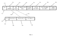
- FIG. 3 provides more detail of signature 212 from first database 210, and signature 232 from second database 230. These are represented in FIG. 3 as signature 312 and signature 332, respectively.
- Signature 312 from first database 310 has been illustrated as comprising multiple measurements. Each of these measurements has suffix 1, to conform to the suffix RF1 used in FIG. 2 for signature 212.
- Signature 332 from second database 330 has been illustrated as comprising multiple measurements. Each of these measurements has suffix 1A, to conform to the suffix RF1A used in FIG. 2 for signature 232.
- Signature 312 comprises: Cell identifier 1, reference 316; Timestamp 1, reference 318; Signal-to-noise ratio 1, reference 320; Channel quality indicator 1, reference 322; Dynamic rate control 1, reference 324; Burst throughput rate control 1, reference 326; Timing advance 1, reference 328.
- Signal to noise ratio and channel quality indicator are examples of quantities used in 'dynamic rate control'.
- the dynamic rate control shown by reference 324 may be based on other parameters than signal to noise ratio and channel quality indicator.
- Signature 332 in this example, comprises: Location information LOC1, reference 334; Power level 1A, reference 336, Observed cells 1A, reference 338; Timestamp 1 A, reference 340.
- Signature 312 will therefore comprise further measurements corresponding to those shown as references 320-328, but for a second cell and other cells. Those additional measurements are not shown on FIG. 3 .
- signature 332 will comprise additional measurements corresponding to the power level measurement in reference 336, but for the second and other cells.
- FIG. 3 has only been drawn to illustrate measurements for a first cell.
- Signature 312 and signature 332 may be linked by using the overlapping timestamp and RF measurements held in the two signatures.
- the timestamp recording is precise, and may typically be recorded in milliseconds.
- the precision of the RF measurement recordings is also high, with recordings typically in deciBels relative to a milliwatt, or dBm.
- the uniqueness of the reported cells may be used, with the cells typically being identified using global cell identifiers.
- dotted line 350 indicates that Observed cells 1A of the signature 332 are found to match Cell identifier 1 of signature 312.
- a 'match' may be an exact correspondence, or a high degree of correlation.
- dotted line 352 indicates that Timestamp 1A of the signature 332 is found to match Timestamp 1 of signature 312.
- the invention may make a match between signatures 332 and 312 using just the timestamp and cell ID information.
- the invention may match the timestamps, the power levels and the observed cells for multiple cells, in order to match signatures 332 and 312.
- the invention may lead to a straight-forward matching between signatures a location poor, information rich database, such as first database 210, and many or all signatures in a location rich, information poor database, such as second database 230.
- Similar links to those shown in FIG. 3 for signatures 332 and 312 may also be found between measurements of parameters in signature 236 from first database 210 and signature 218 from second database 230.
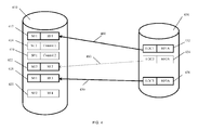
- FIG. 4 illustrates an example of the overall result that may be achieved.
- Signatures 412 and 432 of FIG. 4 correspond to signatures 212 and 232 of FIG. 2 .
- Signatures 418 and 436 correspond to signatures 218 and 236 of FIG. 2 .
- the remaining reference numbers on FIG. 4 that correspond to those of FIG. 2 indicate similar elements to those in FIG. 2 .
- FIG. 4 shows links made between signatures 412 and 432, and between signatures 418 and 436.
- Reference 460 shows the link between signatures 432 and 412.
- Reference 470 shows the link between signatures 436 and 418.
- First database 410 also shows an additional signature with reference 422.
- Signature 422 is for mobile communication unit SU3, which was referred to in the discussion of FIG. 2 .
- the method may create a link 480 between signature 434 in second database 430 and signature 422.
- Link 480 may be based on the correlation between the measurements that make up signatures 434 and signature 422. Those measurements include RF information RF2A within signature 434 and RF information RF2 in signature 422.
- Signature 434 may comprise measurements of the types indicated at references 336, 338 and 340 in FIG. 3 for signature 332.
- Signature 422 may comprise measurements of the types indicated at references 316, 318, 320, 322, 324, 326, 328 in FIG. 3 for signature 312. Some or all of the measurements that make up signature 434 may match exactly or correlate well with the corresponding fields of signature 422.
- FIG. 5 illustrates in general terms the combining of first database 210, or 410, and second database 230, or 430. This is achieved by linking many signatures from database 230, 430 to corresponding signatures in database 210, 410.
- First database 510 is illustrated as being added to second database 530 to form a database 580 of reference signatures.
- One reference signature 582 is shown in database 580.
- Reference signature 582 is a synthesis of signatures 212 and 232.
- Reference signature 582 comprises field 584, which indicates the identity information of mobile communication unit SU1 from signature 212.
- Field 586 indicates the location 'LOC1' from reference signature 232.
- Field 588 generally indicates, as RF1+1A, a synthesis of the other measurements from the two signatures 212 and 232.
- Field 588 may comprise measurements derived from all the fields shown as 316, 318, 320, 322, 324, 326, 328 and 336, 338 and 340 in FIG. 3 .
- the identity of the mobile communication unit may be useful in identifying locations for signatures such as 414 and 416 in database 410 of FIG. 4 .
- reference signature 582 may, in an alternative embodiment, be stored in database 580 without field 584 indicating the identity of the mobile communication unit SU1 from signature 212.
- first database 510 that eventually stores the reference signatures.
- This approach may convert a pre-existing OSS database into a database of reference signatures, for example.
- data from the signatures in first database 510 is added into the corresponding signatures in second database 530, it will be second database 530 that eventually stores the reference signatures.
- first database 510 such as an OSS database
- second database 530 such as an anonymised limited RF database
- Other locations associated with any given user can be similarly applied to the signatures in the first database 510.
- FIG. 6 illustrates a mobile communication system 600 in accordance with an embodiment of the invention.
- Mobile communication system 600 comprises base station BS1 with reference 602, base station BS2 with reference 604 and base station BS3 with reference 606.
- Controller 608 is linked to each of the base stations, and may function to implement the method of the invention. Alternatively, other elements of the mobile communication system 600 may implement all or part of the method of the invention.
- first database 510 also contains other entries, such as signatures 214 and 216, which do not contain full RF information, but have only control information.
- the time stamps of entries in first database 210 show that signatures 214 and 216 are 'intervening events', since they occurred after signature 212 but before signature 218.
- the method described above has provided location estimates for the signatures 212 and 218.
- Each of signatures 214 and 216 can now have a location associated with it. This may be achieved either by interpolating between the locations obtained for signatures 212 and 218, or by extrapolating from the location of one of signatures 212 and 218.
- FIG. 6 shows four successive locations 612, 614, 616 and 618 for a mobile communication unit 620.
- Mobile communication unit 620 is mobile communication unit SU1, which was discussed in connection with FIGs. 2-5 above.
- mobile communication unit 620 was at location 612, it provided reference signatures 212 and 232.
- mobile communication unit 620 was at location 618, it provided reference signatures 218 and 236.
- the method described previously has therefore provided location estimates 'LOC1' for location 612 and 'LOC3' for location 618.
- First database 210 only has control information as part of signatures 214 and 216. However, an estimate of locations 614 and 616 can still be made, by extrapolating between the locations LOC1 and LOC3. For example, the total time difference between the timestamps for reference signatures 212 and 218 can be found by subtraction. Likewise, the spatial separation between locations LOC1 and LOC 3 can be found.
- Location 614 can then be estimated by dividing up the spatial separation between locations LOC1 and LOC 3 in the same proportion as the ratio of (time difference between the timestamp of reference signatures 212 and 214, divided by the total time difference between the timestamps for reference signatures 212 and 218).
- the time difference between the timestamps for reference signatures 212 and 218 may be 10 seconds.
- location 616 lies in the same direction from location 'LOC1' as does 'LOC3'. So location 616 is 18 metres from 'LOC1' and 12 metres from 'LOC3', on a line joining LOC1 and LOC 3.
- FIG. 7 illustrates the estimates discussed above in connection with FIG. 6 .
- first database 210 is illustrated again, as a database with reference 710.
- the reference signatures derived from signatures 212 and 232 and from 218 and 236 have now been stored in first database 210, to provide a database 710 of reference signatures.
- Signature 712 is a synthesis of signatures 212 and 232, and has location information 'LOC1'. So reference signature 712 comprises similar data to that of reference signature 582 in FIG. 5 .
- Reference signature 718 is a synthesis of reference signatures 218 and 236, and has location information 'LOC3'.
- Reference signature 714 is based on reference signature 214. However, the extrapolation approach explained above with reference to FIG. 6 has led to a location estimate for reference signature 714 of: LOC 1 + (x1,y1)
- x1 is a change in x co-ordinate that represents the displacement along the x axis of location 614 relative to LOC1.
- y1 is the displacement along the y axis of location 614 relative to LOC1. If height data were available, then a further term z1 would indicate any change in altitude between location 614 and location 612. Analogously for signature 716, x2 and y2 represent the displacements of location 616 from LOC1.
- FIG. 7 has four reference signatures, each comprising location information. However, the four location estimates all derive from the two location estimates 'LOC1' and 'LOC3', which were part of just the two signatures 232 and 236 of FIG. 2 .
- FIG. 7 illustrates how interpolation or extrapolation of location information may lead to the creation of more useable reference signatures than there were signatures in the anonymised database 230.
- a location-rich but information-poor database can be used in concert with an information-rich but location-poor database.
- the resultant database of reference signatures may then aid in geolocating other calls or connections, which do not comprise location information.
- Arbitrarily complex reference signatures may be generated. These signatures may involve not just Radio Frequency (RF) terms, but other control information terms as well, including Channel Quality Index (CQI), burst rate, serving cell, etc. This permits the construction of reference signatures with location information that are arbitrarily complex in the following sense:
- RF Radio Frequency
- CQI Channel Quality Index
- This approach also ensures that the constructed reference signature database 580, 710 is of great relevance, from a user's perspective. This is the case, because the reference signature database 580, 710 is constructed using randomly selected users. Over time, areas within a mobile communication system 600 that are more frequented by users will tend to be better represented in the reference signature database. This is in contrast to some known drive-test-based strategies, which may be unable to focus on the areas where users are more commonly located.
- the method can be applied to many cellular telecommunications technologies that provide databases that are location-rich but information-poor, as well as databases that are information-rich but location-poor.
- Note-worthy examples are LTE and UMTS.
- FIG. 8 summarises both the creation of the reference signature database 580, 710, and its use in a method of geolocation.
- each signature from second database 230 is correlated or otherwise compared with signatures in first database 210.
- step 820 once a match has been achieved, the location information from each signature in second database 230 is added to the information for the corresponding signature in first database 210.
- step 830 location information is estimated for those signatures in the first database that comprise detail of control events.
- This extrapolation step may, for example, more than double the number of reference signatures that include a location estimate.
- a database 580 or 710 of reference signatures is available. This database can be used in methods such as that explained at length in US application 13/369591 .
- Step 840 illustrates this use.
- a signature is identified that lacks location information.
- This 'unknown' signature may be a record of a call reaching first database 210, when first database 210 is the OSS database of a UMTS mobile communication system.
- the unknown signature may be compared to the reference signatures in database 580 or 710 of reference signatures. When the RF and other measurements in the unknown signature are close enough to those of one of the reference signatures in database 580 or 710 of reference signatures, the location information of that reference signature from database 580 or 710 may be taken to be an estimate of the location of the mobile communication unit that provided the unknown signature.
- the 'unknown' signature processed in step 840 may be a newly arrived signature, which was received after the signatures that make up database 580 or 710 of reference signatures.
- the unknown signature may have been recorded prior to some of the reference signatures in database 580 or 710 of reference signatures. This may be the case, when an attempt is made to geolocate an unknown signature obtained days or even weeks before the reference signatures in database 580 or 710 were captured.
Landscapes
- Engineering & Computer Science (AREA)
- Computer Networks & Wireless Communication (AREA)
- Signal Processing (AREA)
- Physics & Mathematics (AREA)
- General Physics & Mathematics (AREA)
- Radar, Positioning & Navigation (AREA)
- Remote Sensing (AREA)
- Mobile Radio Communication Systems (AREA)
Applications Claiming Priority (1)
| Application Number | Priority Date | Filing Date | Title |
|---|---|---|---|
| US13/719,166 US9439162B2 (en) | 2012-12-18 | 2012-12-18 | Mobile geolocation |
Publications (3)
| Publication Number | Publication Date |
|---|---|
| EP2755431A2 true EP2755431A2 (de) | 2014-07-16 |
| EP2755431A3 EP2755431A3 (de) | 2014-08-06 |
| EP2755431B1 EP2755431B1 (de) | 2016-11-23 |
Family
ID=49999666
Family Applications (1)
| Application Number | Title | Priority Date | Filing Date |
|---|---|---|---|
| EP13197797.7A Active EP2755431B1 (de) | 2012-12-18 | 2013-12-17 | Mobile geolokalisierung |
Country Status (2)
| Country | Link |
|---|---|
| US (2) | US9439162B2 (de) |
| EP (1) | EP2755431B1 (de) |
Cited By (2)
| Publication number | Priority date | Publication date | Assignee | Title |
|---|---|---|---|---|
| FR3074305A1 (fr) * | 2017-11-30 | 2019-05-31 | Sigfox | Procede et systeme de geolocalisation d’un terminal occupant des positions geographiques particulieres |
| RU2774300C2 (ru) * | 2017-11-30 | 2022-06-17 | Сигфокс | Способ и система геолокации терминала, занимающего определенное географическое положение |
Families Citing this family (19)
| Publication number | Priority date | Publication date | Assignee | Title |
|---|---|---|---|---|
| US9439162B2 (en) | 2012-12-18 | 2016-09-06 | Viavi Solutions Uk Limited | Mobile geolocation |
| US9544732B2 (en) | 2012-12-18 | 2017-01-10 | Viavi Solutions Uk Limited | Mobile communication system |
| US9258679B1 (en) * | 2013-07-15 | 2016-02-09 | Google Inc. | Modifying a history of geographic locations of a computing device |
| US9622124B2 (en) | 2014-07-10 | 2017-04-11 | Viavi Solutions Uk Limited | Techniques for improved allocation of network resources using geolocation and handover management |
| US9351172B2 (en) | 2014-07-31 | 2016-05-24 | Viavi Solutions Uk Limited | Techniques for estimating a coverage area for a distributed antenna system (DAS) or a repeater system |
| US9888344B2 (en) | 2014-08-05 | 2018-02-06 | Viavi Solutions Uk Limited | Techniques for multiple pass geolocation |
| US9510209B2 (en) | 2014-12-01 | 2016-11-29 | Viavi Solutions Uk Limited | Techniques for providing a small cell deployment plan |
| EP3030020B1 (de) | 2014-12-01 | 2020-01-08 | Viavi Solutions UK Limited | Bereitstellung von streaming von geolokalisierungsinformationen |
| US9456362B2 (en) | 2015-01-19 | 2016-09-27 | Viavi Solutions Uk Limited | Techniques for dynamic network optimization using geolocation and network modeling |
| US9730086B2 (en) | 2015-01-19 | 2017-08-08 | Viavi Solutions Uk Limited | Techniques for dynamic network optimization using geolocation and network modeling |
| US9635505B2 (en) | 2015-04-29 | 2017-04-25 | Viavi Solutions Uk Limited | Techniques for mobile network geolocation |
| US9848338B2 (en) | 2015-08-05 | 2017-12-19 | Viavi Solutions Uk Limited | Small cell planning |
| EP3239729B1 (de) * | 2016-04-25 | 2024-12-11 | Viavi Solutions UK Limited | Sensorbasierte geolokalisierung einer benutzervorrichtung |
| FR3064074B1 (fr) * | 2017-03-15 | 2019-05-03 | Sigfox | Procede et systeme de geolocalisation d’un terminal d’un systeme de communication sans fil |
| US10382883B2 (en) * | 2017-09-08 | 2019-08-13 | Netscout Systems, Inc. | Automatic calibration of geolocation analytic systems and operator network equipment parameters |
| EP3888381A4 (de) * | 2018-11-30 | 2021-12-15 | Telefonaktiebolaget LM Ericsson (publ) | Positionierung in drahtloskommunikationsnetzen |
| US11288347B2 (en) * | 2019-03-07 | 2022-03-29 | Paypal, Inc. | Login from an alternate electronic device |
| EP4010820B1 (de) * | 2019-08-09 | 2024-10-02 | PCTEL, Inc. | Systeme und verfahren zum wiederauffinden von spezifischen und benachbarten strukturnetzwerkkarten in echtzeit |
| CN114466451B (zh) * | 2022-04-08 | 2022-07-05 | 成都瀚德科技有限公司 | 基于路测频谱数据的定位方法、定位装置以及存储介质 |
Citations (3)
| Publication number | Priority date | Publication date | Assignee | Title |
|---|---|---|---|---|
| WO2010083943A1 (en) | 2009-01-22 | 2010-07-29 | Arieso Limited | Determining differences between base station timing offset for pairs of base stations in asynchronous networks using location estimates |
| US20130143588A1 (en) | 2011-12-05 | 2013-06-06 | Michael Joseph Flanagan | System and methods of mobile geolocation |
| US20130210449A1 (en) | 2012-02-09 | 2013-08-15 | Michael Joseph Flanagan | Mobile geolocation |
Family Cites Families (15)
| Publication number | Priority date | Publication date | Assignee | Title |
|---|---|---|---|---|
| US2309336A (en) | 1938-08-26 | 1943-01-26 | Continental Oil Co | Addition agent for lubricating oils |
| US20060126556A1 (en) * | 2004-12-14 | 2006-06-15 | Roundbox, Inc. | Territory mapping for efficient content distribution in wireless networks using broadcast/multicast |
| US8493443B2 (en) * | 2005-01-04 | 2013-07-23 | Hewlett-Packard Development Company, L.P. | Methods and apparatus for location determination and asserting and maintaining privacy |
| WO2007091934A1 (en) | 2006-02-10 | 2007-08-16 | Telefonaktiebolaget Lm Ericsson (Publ) | Performance monitoring of location-based service in a mobile telecommunications network |
| US20090181664A1 (en) * | 2008-01-15 | 2009-07-16 | Eapen Kuruvilla | Method and apparatus for network managed radio frequency coverage and mobile distribution analysis using mobile location information |
| US8959108B2 (en) * | 2008-06-18 | 2015-02-17 | Zeitera, Llc | Distributed and tiered architecture for content search and content monitoring |
| CN101621739A (zh) * | 2008-06-30 | 2010-01-06 | 深圳富泰宏精密工业有限公司 | 信号采集系统及方法 |
| JP5413073B2 (ja) | 2009-09-11 | 2014-02-12 | ソニー株式会社 | 移動局装置、基地局装置および無線通信システム |
| EP4033824A1 (de) * | 2010-03-12 | 2022-07-27 | BlackBerry Limited | Kommunikationsstation und verfahren zur übertragung auf einem direktzugriffskanal |
| US9582839B2 (en) * | 2011-03-22 | 2017-02-28 | At&T Intellectual Property I, L.P. | Notifying of health events in peer environments |
| US8615229B2 (en) * | 2011-03-31 | 2013-12-24 | Alcatel Lucent | Mobile unit and network element for testing RF coverage |
| KR20140018908A (ko) * | 2011-04-05 | 2014-02-13 | 텔레호낙티에볼라게트 엘엠 에릭슨(피유비엘) | 채널 핑거프린트에 기초한 자율적 최대 전력 설정 |
| JP5741223B2 (ja) * | 2011-05-31 | 2015-07-01 | 富士通株式会社 | 情報処理装置、補正方法、及び補正プログラム |
| US9439162B2 (en) | 2012-12-18 | 2016-09-06 | Viavi Solutions Uk Limited | Mobile geolocation |
| EP3454594B1 (de) | 2013-06-11 | 2020-11-04 | Seven Networks, LLC | Offload von anwendungsverkehr auf einen gemeinsamen kommunikationskanal zur signaloptimierung in einem drahtlosen netzwerk für verkehr unter verwendung von proprietären und nicht-proprietären protokollen |
-
2012
- 2012-12-18 US US13/719,166 patent/US9439162B2/en active Active
-
2013
- 2013-12-17 EP EP13197797.7A patent/EP2755431B1/de active Active
-
2016
- 2016-09-01 US US15/254,603 patent/US9907048B2/en active Active
Patent Citations (3)
| Publication number | Priority date | Publication date | Assignee | Title |
|---|---|---|---|---|
| WO2010083943A1 (en) | 2009-01-22 | 2010-07-29 | Arieso Limited | Determining differences between base station timing offset for pairs of base stations in asynchronous networks using location estimates |
| US20130143588A1 (en) | 2011-12-05 | 2013-06-06 | Michael Joseph Flanagan | System and methods of mobile geolocation |
| US20130210449A1 (en) | 2012-02-09 | 2013-08-15 | Michael Joseph Flanagan | Mobile geolocation |
Non-Patent Citations (1)
| Title |
|---|
| M.F. KHAN: "Mobile Cellular Location Positioning: An Approach Combining Radio Signal Strength Propagation and Trilateration", MASTERS THESIS, November 2009 (2009-11-01) |
Cited By (6)
| Publication number | Priority date | Publication date | Assignee | Title |
|---|---|---|---|---|
| FR3074305A1 (fr) * | 2017-11-30 | 2019-05-31 | Sigfox | Procede et systeme de geolocalisation d’un terminal occupant des positions geographiques particulieres |
| WO2019106128A1 (fr) * | 2017-11-30 | 2019-06-06 | Sigfox | Procédé et système de géolocalisation d'un terminal occupant des positions géographiques particulières |
| CN111433624A (zh) * | 2017-11-30 | 2020-07-17 | 西格弗克斯公司 | 用于对占据特定地理位置的终端进行地理定位的方法和系统 |
| RU2774300C2 (ru) * | 2017-11-30 | 2022-06-17 | Сигфокс | Способ и система геолокации терминала, занимающего определенное географическое положение |
| CN111433624B (zh) * | 2017-11-30 | 2024-05-24 | 优纳比公司 | 用于对占据特定地理位置的终端进行地理定位的方法和系统 |
| US12105215B2 (en) | 2017-11-30 | 2024-10-01 | Unabiz | Method and system for geolocating a terminal occupying particular geographical positions |
Also Published As
| Publication number | Publication date |
|---|---|
| US20140171102A1 (en) | 2014-06-19 |
| EP2755431B1 (de) | 2016-11-23 |
| US20170064669A1 (en) | 2017-03-02 |
| US9907048B2 (en) | 2018-02-27 |
| EP2755431A3 (de) | 2014-08-06 |
| US9439162B2 (en) | 2016-09-06 |
Similar Documents
| Publication | Publication Date | Title |
|---|---|---|
| EP2755431B1 (de) | Mobile geolokalisierung | |
| EP2755432B1 (de) | Verfahren und system zur mobilen referenzsignaturerzeugung | |
| JP6159321B2 (ja) | 無線ネットワークのカバレージ・エリア内で動作パラメータをマッピングする方法および装置 | |
| US8073463B2 (en) | System and method of UMTS UE location using uplink dedicated physical control channel and downlink synchronization channel | |
| US8433250B2 (en) | Estimating whether a wireless terminal is indoors using pattern classification | |
| EP2755433B1 (de) | Mobilkommunikationssystem | |
| KR100952338B1 (ko) | 유피셀 데이터베이스 구축 방법, 유피셀 데이터베이스업데이트 방법, 유피셀 데이터베이스를 이용한 네트워크기반의 위치 측정 방법, 서버 및 시스템 | |
| CN104322119A (zh) | 监测基于陆地无线电的定位系统的质量 | |
| CN104205964A (zh) | 移动地理定位 | |
| US8744479B2 (en) | Method and locating device for locating at least one mobile radio subscriber | |
| US20070117573A1 (en) | System and method for generating geocoded data for network optimization under different network architectures and location technology conditions | |
| US7804786B2 (en) | Method and apparatus for determining path loss by combining geolocation with interference suppression | |
| US9414291B2 (en) | Dynamic tag control and fingerprinting event localization | |
| US10200965B2 (en) | Analysis and monitoring of a positioning infrastructure | |
| Hiltunen et al. | Performance evaluation of LTE radio fingerprint positioning with timing advancing | |
| JP2009525483A (ja) | 屋内における高精度位置基準測定のための方法及び装置 | |
| CN106796277B (zh) | 移动通信网络中的位置调整 | |
| Fida et al. | Impact of device diversity on crowdsourced mobile coverage maps | |
| CN105338487B (zh) | 用于多遍地理定位的技术 | |
| EP2957923A1 (de) | Verfahren zur Verbesserung der Messdaten pro Anruf und Prozessor dafür | |
| US20130154883A1 (en) | Positioning error calculation device, positioning error calculation system and positioning error calculation method | |
| Vieira et al. | A SON enhanced algorithm for observed time differences based geolocation in real 3G networks | |
| JP2014003443A (ja) | 無線通信端末の位置に応じてサービス提供の可否を制御するシステム及び方法 | |
| Samuel et al. | Location-based performance-measuring techniques in UMTS |
Legal Events
| Date | Code | Title | Description |
|---|---|---|---|
| PUAL | Search report despatched |
Free format text: ORIGINAL CODE: 0009013 |
|
| PUAI | Public reference made under article 153(3) epc to a published international application that has entered the european phase |
Free format text: ORIGINAL CODE: 0009012 |
|
| 17P | Request for examination filed |
Effective date: 20131217 |
|
| AK | Designated contracting states |
Kind code of ref document: A2 Designated state(s): AL AT BE BG CH CY CZ DE DK EE ES FI FR GB GR HR HU IE IS IT LI LT LU LV MC MK MT NL NO PL PT RO RS SE SI SK SM TR |
|
| AX | Request for extension of the european patent |
Extension state: BA ME |
|
| AK | Designated contracting states |
Kind code of ref document: A3 Designated state(s): AL AT BE BG CH CY CZ DE DK EE ES FI FR GB GR HR HU IE IS IT LI LT LU LV MC MK MT NL NO PL PT RO RS SE SI SK SM TR |
|
| AX | Request for extension of the european patent |
Extension state: BA ME |
|
| RIC1 | Information provided on ipc code assigned before grant |
Ipc: H04W 24/08 20090101ALN20140630BHEP Ipc: G01S 5/02 20100101ALI20140630BHEP Ipc: H04W 64/00 20090101AFI20140630BHEP |
|
| R17P | Request for examination filed (corrected) |
Effective date: 20150206 |
|
| RBV | Designated contracting states (corrected) |
Designated state(s): AL AT BE BG CH CY CZ DE DK EE ES FI FR GB GR HR HU IE IS IT LI LT LU LV MC MK MT NL NO PL PT RO RS SE SI SK SM TR |
|
| 17Q | First examination report despatched |
Effective date: 20151214 |
|
| RAP1 | Party data changed (applicant data changed or rights of an application transferred) |
Owner name: VIAVI SOLUTIONS UK LIMITED |
|
| GRAP | Despatch of communication of intention to grant a patent |
Free format text: ORIGINAL CODE: EPIDOSNIGR1 |
|
| RIC1 | Information provided on ipc code assigned before grant |
Ipc: G01S 5/02 20060101ALI20160504BHEP Ipc: H04W 24/08 20090101ALN20160504BHEP Ipc: H04W 64/00 20090101AFI20160504BHEP |
|
| INTG | Intention to grant announced |
Effective date: 20160608 |
|
| GRAS | Grant fee paid |
Free format text: ORIGINAL CODE: EPIDOSNIGR3 |
|
| GRAA | (expected) grant |
Free format text: ORIGINAL CODE: 0009210 |
|
| RAP1 | Party data changed (applicant data changed or rights of an application transferred) |
Owner name: VIAVI SOLUTIONS UK LIMITED |
|
| RIN1 | Information on inventor provided before grant (corrected) |
Inventor name: KENINGTON, PETER Inventor name: FLANAGAN, MICHAEL Inventor name: MURPHY, CHRISTOPHER |
|
| AK | Designated contracting states |
Kind code of ref document: B1 Designated state(s): AL AT BE BG CH CY CZ DE DK EE ES FI FR GB GR HR HU IE IS IT LI LT LU LV MC MK MT NL NO PL PT RO RS SE SI SK SM TR |
|
| REG | Reference to a national code |
Ref country code: GB Ref legal event code: FG4D |
|
| REG | Reference to a national code |
Ref country code: CH Ref legal event code: EP |
|
| REG | Reference to a national code |
Ref country code: IE Ref legal event code: FG4D |
|
| REG | Reference to a national code |
Ref country code: AT Ref legal event code: REF Ref document number: 848877 Country of ref document: AT Kind code of ref document: T Effective date: 20161215 |
|
| REG | Reference to a national code |
Ref country code: DE Ref legal event code: R096 Ref document number: 602013014353 Country of ref document: DE |
|
| REG | Reference to a national code |
Ref country code: FR Ref legal event code: PLFP Year of fee payment: 4 |
|
| PG25 | Lapsed in a contracting state [announced via postgrant information from national office to epo] |
Ref country code: LV Free format text: LAPSE BECAUSE OF FAILURE TO SUBMIT A TRANSLATION OF THE DESCRIPTION OR TO PAY THE FEE WITHIN THE PRESCRIBED TIME-LIMIT Effective date: 20161123 |
|
| REG | Reference to a national code |
Ref country code: LT Ref legal event code: MG4D |
|
| REG | Reference to a national code |
Ref country code: NL Ref legal event code: MP Effective date: 20161123 |
|
| REG | Reference to a national code |
Ref country code: AT Ref legal event code: MK05 Ref document number: 848877 Country of ref document: AT Kind code of ref document: T Effective date: 20161123 |
|
| PG25 | Lapsed in a contracting state [announced via postgrant information from national office to epo] |
Ref country code: NO Free format text: LAPSE BECAUSE OF FAILURE TO SUBMIT A TRANSLATION OF THE DESCRIPTION OR TO PAY THE FEE WITHIN THE PRESCRIBED TIME-LIMIT Effective date: 20170223 Ref country code: NL Free format text: LAPSE BECAUSE OF FAILURE TO SUBMIT A TRANSLATION OF THE DESCRIPTION OR TO PAY THE FEE WITHIN THE PRESCRIBED TIME-LIMIT Effective date: 20161123 Ref country code: GR Free format text: LAPSE BECAUSE OF FAILURE TO SUBMIT A TRANSLATION OF THE DESCRIPTION OR TO PAY THE FEE WITHIN THE PRESCRIBED TIME-LIMIT Effective date: 20170224 Ref country code: SE Free format text: LAPSE BECAUSE OF FAILURE TO SUBMIT A TRANSLATION OF THE DESCRIPTION OR TO PAY THE FEE WITHIN THE PRESCRIBED TIME-LIMIT Effective date: 20161123 Ref country code: LT Free format text: LAPSE BECAUSE OF FAILURE TO SUBMIT A TRANSLATION OF THE DESCRIPTION OR TO PAY THE FEE WITHIN THE PRESCRIBED TIME-LIMIT Effective date: 20161123 |
|
| PG25 | Lapsed in a contracting state [announced via postgrant information from national office to epo] |
Ref country code: HR Free format text: LAPSE BECAUSE OF FAILURE TO SUBMIT A TRANSLATION OF THE DESCRIPTION OR TO PAY THE FEE WITHIN THE PRESCRIBED TIME-LIMIT Effective date: 20161123 Ref country code: RS Free format text: LAPSE BECAUSE OF FAILURE TO SUBMIT A TRANSLATION OF THE DESCRIPTION OR TO PAY THE FEE WITHIN THE PRESCRIBED TIME-LIMIT Effective date: 20161123 Ref country code: FI Free format text: LAPSE BECAUSE OF FAILURE TO SUBMIT A TRANSLATION OF THE DESCRIPTION OR TO PAY THE FEE WITHIN THE PRESCRIBED TIME-LIMIT Effective date: 20161123 Ref country code: PL Free format text: LAPSE BECAUSE OF FAILURE TO SUBMIT A TRANSLATION OF THE DESCRIPTION OR TO PAY THE FEE WITHIN THE PRESCRIBED TIME-LIMIT Effective date: 20161123 Ref country code: BE Free format text: LAPSE BECAUSE OF NON-PAYMENT OF DUE FEES Effective date: 20161231 Ref country code: ES Free format text: LAPSE BECAUSE OF FAILURE TO SUBMIT A TRANSLATION OF THE DESCRIPTION OR TO PAY THE FEE WITHIN THE PRESCRIBED TIME-LIMIT Effective date: 20161123 Ref country code: PT Free format text: LAPSE BECAUSE OF FAILURE TO SUBMIT A TRANSLATION OF THE DESCRIPTION OR TO PAY THE FEE WITHIN THE PRESCRIBED TIME-LIMIT Effective date: 20170323 Ref country code: AT Free format text: LAPSE BECAUSE OF FAILURE TO SUBMIT A TRANSLATION OF THE DESCRIPTION OR TO PAY THE FEE WITHIN THE PRESCRIBED TIME-LIMIT Effective date: 20161123 |
|
| PG25 | Lapsed in a contracting state [announced via postgrant information from national office to epo] |
Ref country code: DK Free format text: LAPSE BECAUSE OF FAILURE TO SUBMIT A TRANSLATION OF THE DESCRIPTION OR TO PAY THE FEE WITHIN THE PRESCRIBED TIME-LIMIT Effective date: 20161123 Ref country code: RO Free format text: LAPSE BECAUSE OF FAILURE TO SUBMIT A TRANSLATION OF THE DESCRIPTION OR TO PAY THE FEE WITHIN THE PRESCRIBED TIME-LIMIT Effective date: 20161123 Ref country code: SK Free format text: LAPSE BECAUSE OF FAILURE TO SUBMIT A TRANSLATION OF THE DESCRIPTION OR TO PAY THE FEE WITHIN THE PRESCRIBED TIME-LIMIT Effective date: 20161123 Ref country code: EE Free format text: LAPSE BECAUSE OF FAILURE TO SUBMIT A TRANSLATION OF THE DESCRIPTION OR TO PAY THE FEE WITHIN THE PRESCRIBED TIME-LIMIT Effective date: 20161123 Ref country code: CZ Free format text: LAPSE BECAUSE OF FAILURE TO SUBMIT A TRANSLATION OF THE DESCRIPTION OR TO PAY THE FEE WITHIN THE PRESCRIBED TIME-LIMIT Effective date: 20161123 |
|
| REG | Reference to a national code |
Ref country code: CH Ref legal event code: PL |
|
| REG | Reference to a national code |
Ref country code: DE Ref legal event code: R097 Ref document number: 602013014353 Country of ref document: DE |
|
| PG25 | Lapsed in a contracting state [announced via postgrant information from national office to epo] |
Ref country code: BG Free format text: LAPSE BECAUSE OF FAILURE TO SUBMIT A TRANSLATION OF THE DESCRIPTION OR TO PAY THE FEE WITHIN THE PRESCRIBED TIME-LIMIT Effective date: 20170223 Ref country code: SM Free format text: LAPSE BECAUSE OF FAILURE TO SUBMIT A TRANSLATION OF THE DESCRIPTION OR TO PAY THE FEE WITHIN THE PRESCRIBED TIME-LIMIT Effective date: 20161123 Ref country code: IT Free format text: LAPSE BECAUSE OF FAILURE TO SUBMIT A TRANSLATION OF THE DESCRIPTION OR TO PAY THE FEE WITHIN THE PRESCRIBED TIME-LIMIT Effective date: 20161123 Ref country code: BE Free format text: LAPSE BECAUSE OF FAILURE TO SUBMIT A TRANSLATION OF THE DESCRIPTION OR TO PAY THE FEE WITHIN THE PRESCRIBED TIME-LIMIT Effective date: 20161123 |
|
| PG25 | Lapsed in a contracting state [announced via postgrant information from national office to epo] |
Ref country code: MC Free format text: LAPSE BECAUSE OF FAILURE TO SUBMIT A TRANSLATION OF THE DESCRIPTION OR TO PAY THE FEE WITHIN THE PRESCRIBED TIME-LIMIT Effective date: 20161123 |
|
| PLBE | No opposition filed within time limit |
Free format text: ORIGINAL CODE: 0009261 |
|
| STAA | Information on the status of an ep patent application or granted ep patent |
Free format text: STATUS: NO OPPOSITION FILED WITHIN TIME LIMIT |
|
| REG | Reference to a national code |
Ref country code: IE Ref legal event code: MM4A |
|
| PG25 | Lapsed in a contracting state [announced via postgrant information from national office to epo] |
Ref country code: CH Free format text: LAPSE BECAUSE OF NON-PAYMENT OF DUE FEES Effective date: 20161231 Ref country code: LI Free format text: LAPSE BECAUSE OF NON-PAYMENT OF DUE FEES Effective date: 20161231 Ref country code: LU Free format text: LAPSE BECAUSE OF NON-PAYMENT OF DUE FEES Effective date: 20161217 |
|
| 26N | No opposition filed |
Effective date: 20170824 |
|
| PG25 | Lapsed in a contracting state [announced via postgrant information from national office to epo] |
Ref country code: SI Free format text: LAPSE BECAUSE OF FAILURE TO SUBMIT A TRANSLATION OF THE DESCRIPTION OR TO PAY THE FEE WITHIN THE PRESCRIBED TIME-LIMIT Effective date: 20161123 Ref country code: IE Free format text: LAPSE BECAUSE OF NON-PAYMENT OF DUE FEES Effective date: 20161217 |
|
| REG | Reference to a national code |
Ref country code: FR Ref legal event code: PLFP Year of fee payment: 5 |
|
| PG25 | Lapsed in a contracting state [announced via postgrant information from national office to epo] |
Ref country code: HU Free format text: LAPSE BECAUSE OF FAILURE TO SUBMIT A TRANSLATION OF THE DESCRIPTION OR TO PAY THE FEE WITHIN THE PRESCRIBED TIME-LIMIT; INVALID AB INITIO Effective date: 20131217 |
|
| PG25 | Lapsed in a contracting state [announced via postgrant information from national office to epo] |
Ref country code: IS Free format text: LAPSE BECAUSE OF FAILURE TO SUBMIT A TRANSLATION OF THE DESCRIPTION OR TO PAY THE FEE WITHIN THE PRESCRIBED TIME-LIMIT Effective date: 20161123 Ref country code: MK Free format text: LAPSE BECAUSE OF FAILURE TO SUBMIT A TRANSLATION OF THE DESCRIPTION OR TO PAY THE FEE WITHIN THE PRESCRIBED TIME-LIMIT Effective date: 20161123 Ref country code: CY Free format text: LAPSE BECAUSE OF FAILURE TO SUBMIT A TRANSLATION OF THE DESCRIPTION OR TO PAY THE FEE WITHIN THE PRESCRIBED TIME-LIMIT Effective date: 20161123 |
|
| PG25 | Lapsed in a contracting state [announced via postgrant information from national office to epo] |
Ref country code: MT Free format text: LAPSE BECAUSE OF NON-PAYMENT OF DUE FEES Effective date: 20161217 |
|
| PG25 | Lapsed in a contracting state [announced via postgrant information from national office to epo] |
Ref country code: TR Free format text: LAPSE BECAUSE OF FAILURE TO SUBMIT A TRANSLATION OF THE DESCRIPTION OR TO PAY THE FEE WITHIN THE PRESCRIBED TIME-LIMIT Effective date: 20161123 |
|
| PG25 | Lapsed in a contracting state [announced via postgrant information from national office to epo] |
Ref country code: AL Free format text: LAPSE BECAUSE OF FAILURE TO SUBMIT A TRANSLATION OF THE DESCRIPTION OR TO PAY THE FEE WITHIN THE PRESCRIBED TIME-LIMIT Effective date: 20161123 |
|
| PGFP | Annual fee paid to national office [announced via postgrant information from national office to epo] |
Ref country code: GB Payment date: 20251230 Year of fee payment: 13 |
|
| PGFP | Annual fee paid to national office [announced via postgrant information from national office to epo] |
Ref country code: FR Payment date: 20251229 Year of fee payment: 13 |
|
| PGFP | Annual fee paid to national office [announced via postgrant information from national office to epo] |
Ref country code: DE Payment date: 20251230 Year of fee payment: 13 |