EP4010820B1 - Systeme und verfahren zum wiederauffinden von spezifischen und benachbarten strukturnetzwerkkarten in echtzeit - Google Patents
Systeme und verfahren zum wiederauffinden von spezifischen und benachbarten strukturnetzwerkkarten in echtzeit Download PDFInfo
- Publication number
- EP4010820B1 EP4010820B1 EP20851904.1A EP20851904A EP4010820B1 EP 4010820 B1 EP4010820 B1 EP 4010820B1 EP 20851904 A EP20851904 A EP 20851904A EP 4010820 B1 EP4010820 B1 EP 4010820B1
- Authority
- EP
- European Patent Office
- Prior art keywords
- user device
- alert
- coverage data
- location
- coverage
- Prior art date
- Legal status (The legal status is an assumption and is not a legal conclusion. Google has not performed a legal analysis and makes no representation as to the accuracy of the status listed.)
- Active
Links
Images


Classifications
-
- G—PHYSICS
- G08—SIGNALLING
- G08B—SIGNALLING SYSTEMS, e.g. PERSONAL CALLING SYSTEMS; ORDER TELEGRAPHS; ALARM SYSTEMS
- G08B27/00—Alarm systems in which the alarm condition is signalled from a central station to a plurality of substations
- G08B27/001—Signalling to an emergency team, e.g. firemen
-
- G—PHYSICS
- G08—SIGNALLING
- G08B—SIGNALLING SYSTEMS, e.g. PERSONAL CALLING SYSTEMS; ORDER TELEGRAPHS; ALARM SYSTEMS
- G08B21/00—Alarms responsive to a single specified undesired or abnormal condition and not otherwise provided for
- G08B21/02—Alarms for ensuring the safety of persons
-
- H—ELECTRICITY
- H04—ELECTRIC COMMUNICATION TECHNIQUE
- H04W—WIRELESS COMMUNICATION NETWORKS
- H04W4/00—Services specially adapted for wireless communication networks; Facilities therefor
- H04W4/02—Services making use of location information
- H04W4/023—Services making use of location information using mutual or relative location information between multiple location based services [LBS] targets or of distance thresholds
-
- H—ELECTRICITY
- H04—ELECTRIC COMMUNICATION TECHNIQUE
- H04W—WIRELESS COMMUNICATION NETWORKS
- H04W4/00—Services specially adapted for wireless communication networks; Facilities therefor
- H04W4/02—Services making use of location information
- H04W4/029—Location-based management or tracking services
-
- H—ELECTRICITY
- H04—ELECTRIC COMMUNICATION TECHNIQUE
- H04W—WIRELESS COMMUNICATION NETWORKS
- H04W4/00—Services specially adapted for wireless communication networks; Facilities therefor
- H04W4/90—Services for handling of emergency or hazardous situations, e.g. earthquake and tsunami warning systems [ETWS]
-
- G—PHYSICS
- G08—SIGNALLING
- G08B—SIGNALLING SYSTEMS, e.g. PERSONAL CALLING SYSTEMS; ORDER TELEGRAPHS; ALARM SYSTEMS
- G08B21/00—Alarms responsive to a single specified undesired or abnormal condition and not otherwise provided for
- G08B21/18—Status alarms
- G08B21/22—Status alarms responsive to presence or absence of persons
Definitions
- the present invention relates generally to systems and methods for retrieving specific and adjacent structure network maps in real time.
- Known systems and methods for testing a public safety network in a building include a user walking through the building to collect coverage data of the public safety network for a public safety communication system and spatially organizing the coverage data via a grid overlaid on a floor plan of the building on a floor by floor basis. Then, municipalities can use the coverage data to certify the building as being suitable for occupancy and being minimally or reasonably covered by the public safety network for public safety scenarios, for example, to ensure that an emergency responder, such as police department, fire department, and/or EMT personnel, have direct access to the public safety communication system during an emergency situation.
- an emergency responder such as police department, fire department, and/or EMT personnel
- the emergency responder may enter the building without knowledge of the areas where he will likely lose communication with teammates and the like.
- Systems and methods have been developed to train and implement tactics for the emergency responder to operate when he loses communication, but only after such a loss occurs.
- only the emergency responder who loses the communication knows where he is located within the building, and when such a loss occurs, he cannot transmit any outgoing information or receive any incoming information.
- emergency personnel at a command center may have access to a map of the building, but is reliant on the public safety network to communicate with the emergency responder in the building to warn the emergency responder about any danger within the building.
- Unites States Patent Application Publication US 2013/0295853 A1 relates to a wireless communication system and a method to provide wireless communication between a first communication component and a second communication component.
- strength of a signal between the first and second communication components is monitored. If the strength of the signal drops below a threshold, an alert is generated.
- Embodiments disclosed herein can include systems and methods for retrieving specific and adjacent structure network maps, including RF coverage data, in real time.
- systems and methods disclosed herein can load a computation device available to emergency personnel at a command center and/or an emergency responder entering a target building during an emergency therein with coverage information necessary to inform the emergency personnel and the emergency responder about coverage limitations in the building.
- the computation device can be loaded with the coverage information in real time while the emergency responder is in transit to the building and during the emergency, and in some embodiments, the computation device can be loaded with the coverage information at a home location of the emergency responder in response to notifications concerning the emergency.
- systems and methods can store grid test results, that is, the RF coverage data, and/or certification results based on the grid test results in a database that organizes, stores, and/or cross-references the grid test results with geographic information for locations related to the grid test results, for example, where underlying data associated with the grid test results was collected or where the underlying data associated with the grid test results originated.
- the geographic information can include a building address, a property identification number (PIN), a GPS location, a GPS index, a building diagram, and/or a height of a building.
- the target building can include the building in which the emergency has been identified, and systems and methods disclosed herein can use the grid test results and/or the certification results for the target building and/or from buildings surrounding the target building, that is, adjacent buildings, for example, when the grid test results and/or the certification results are unavailable for the target building, to load the computation device with the coverage information.
- the computation device can access the database via a website either directly by entering the building address of the target building or via a link received from the emergency personnel to view the coverage information for the target building and the adjacent buildings.
- systems and methods disclosed herein can visually present the coverage information in 2D and/or 3D, for example, on a map, on a user interface device of the computation device to provide guidance to the emergency responder regarding areas in the target building where, based on the coverage information, poor coverage likely exists, and, therefore, that should be avoided. For example, during a fire in an apartment on a twenty-first floor of a high rise building, if there is poor coverage in a northeast stairwell on floors 15-18, then systems and methods disclosed herein can visually present the coverage information indicative of that poor coverage on the map displayed on the computation device and, in some embodiments, display a path directing the emergency responder to reach the twenty-first floor via southeast or northwest stairwells, thereby avoid the areas with the poor coverage.
- systems and methods disclosed herein can display grid test points where the coverage limitations likely exist, that is, where the grid test points failed a coverage test, and shade those grid test points in one color, for example, red.
- a plurality of emergency responders can enter the target building, and each of the plurality of emergency responders can carry a respective computation device that includes a respective radio.
- the respective radio of the respective computation device carried by each of the plurality of emergency responders can transmit the coverage information and real time coverage signals detected and/or generated thereby to the respective computation device carried by other ones of the plurality of emergency responders as each of the plurality of emergency responders traverses the target building.
- the respective computation device carried by each of the plurality of emergency responders can use a combination of GPS signals and the coverage information and the real time coverage signals generated or received thereby to track other ones of the plurality of emergency responders and alert a respective one of the plurality of emergency responders and/or the emergency personnel when that one of the plurality of emergency responders is proximate any of the areas with the poor coverage.
- the respective computation device carried by each of the plurality of emergency responders can include a tactile feedback mechanism that can vibrate in a first pattern when detecting proximity to any of the areas with the poor coverage and that can vibrate in a second, different pattern when entering any of the areas with sufficient coverage after being located in any of the areas with the poor coverage.
- the respective computation device carried by each of the plurality of emergency responders can transmit notification signals to the command center when detecting proximity to any of the areas with the poor coverage.
- Exemplary, but non-limiting use case scenarios of systems and methods disclosed herein can include fire department personnel driving to the target building and/or a fire chief using the coverage information to organize a plan of attacking a fire in the target building while staying in communication with each other, police department personnel responding to an emergency response, swat, hostage, and/or shooting event using the coverage information to be aware of all of the areas with the poor coverage prior to entering the target building, a surveillance team using the coverage information to ensure that all of the areas in the adjacent buildings relevant to surveilling the target building have the sufficient coverage, and/or EMT personnel using the coverage information to identify a need for relay personnel to call a hospital or a doctor when treating a patient in any of the areas with the poor coverage.
- FIG. 1 is a system 20 according to disclosed embodiments.
- the system 20 can include a dispatch server 22 located at an emergency dispatch location, a municipal database device 24 remotely located from the emergency dispatch location, a first user device 26, and a second user device 27.
- the dispatch server 22 can include a programmable processor 28 and a dispatch database device 30.
- the first user device 26 can include a communication device worn by an emergency responder when responding to an emergency.
- the second user device 27 can include a tablet, a personal computer device, a mobile device, etc. that can display RF coverage data for an identified geographic location in which an emergency is located, and in some embodiments, the identified geographic location can include a target building, the RF coverage data can be related to the target building and/or adjacent buildings thereto.
- FIG. 2 is a flow diagram of an unclaimed method 100 according to disclosed embodiments.
- the method 100 can include the programmable processor 28 receiving user input defining a boundary of a first coverage area of an emergency dispatch location associated with the dispatch server 22, as in 102. Then, the method 100 can include the programmable processor 28 accessing the municipal database device 24 to retrieve a batch of RF coverage data relevant to the first coverage area and storing or caching the batch of RF coverage data in the dispatch database device 30, as in 104.
- the batch of RF coverage data can relate to (1) geographic locations within the first coverage area, (2) geographic locations within second coverage areas of other emergency dispatch locations adjacent to the first coverage area, and (3) geographic locations adjacent to the boundary of the first coverage area.
- the method 100 includes the programmable processor 28 receiving a notification of an emergency event at the identified geographic location, as in 105. Then, the method 100 includes the programmable processor 28 retrieving the RF coverage data for the identified geographic location.
- the method 100 can include the programmable processor 28 (1) determining whether the RF coverage data for the identified geographic location is cached on the dispatch database device 30, as in 106, (2) when the RF coverage data for the identified geographic location is cached on the dispatch database device 30, pushing the RF coverage data for the identified geographic location to the second user device 27, as in 108, and (3) when the RF coverage data for the identified geographic location fails to be cached on the dispatch database device 30, directing the second user device 27 to retrieve the RF coverage data for the identified geographic location from the municipal database device 24, as in 110.
- the method 100 can include the programmable processor 28 determining that the RF coverage data for the identified geographic location is cached on the dispatch database device 30 when the RF coverage data for the identified geographic location is included in the batch of RF coverage data previously stored in the dispatch database device 30, as in 104. Finally, the method 100 can include the second user device 27 displaying the specific RF coverage data, as in 112.
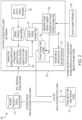
- FIG. 3 is a flow diagram of a method 200 according to the present invention.
- the RF coverage data for the identified geographic region is divided into a plurality of grid cells 32 that include passing grid cells 34 (i.e. where the RF coverage data is above a predetermined threshold), failing grid cells 36 (i.e. where the RF coverage data is below the predetermined threshold), untested grid cells 38 (i.e. where no RF coverage data is available) and out of coverage grid cells (i.e. where RF coverage is known to be zero).
- the method 200 includes the dispatch device 22 or the first user device 26 tracking an ambient location of the first user device 26, as in 202.
- the method 200 includes the dispatch device 22 or the first user device 26 detecting when the ambient location of the first user device indicates proximity to and/or possible or likely entry of the first user device 26 to the failing grid cells 36, for example, based on a direction of travel and/or previously tracked locations of the first user device 26 within the identified geographic location, as in 204.
- the dispatch device 22 or the first user device 26 detects the ambient location of the first user device 26 indicating proximity to and/or possible or likely entry of the first user device 26 to the failing grid cells 36
- the method 200 includes the dispatch device 22 transmitting a first alert to the first user device 26 and the first user device 26 generating the first alert that visually or physically informs a user of the first user device 26 that he is proximate to and/or likely to enter the failing grid cells 36.
- the method 200 includes the dispatch device 22 or the first user device 26 detecting when the ambient location of the first user device 26 indicates proximity to and/or possible or likely entry of the first user device 26 to the untested grid cells 38, and responsive thereto, the dispatch device 22 transmitting a second alert to the first user device 26 and the first user device 26 generating the second alert that visually or physically informs the user of the first user device 26 that he is proximate to and/or likely to enter the untested grid cells 38.
- the method 200 can also include the first user device 26 broadcasting a third alert when the first user device 26 detects its ambient location within the failing grid cells 36, as in 206, and can broadcast a fourth alert when the first user device 26 detects its ambient location within the untested or out of coverage grid cells 38, as in 208.
- the method 200 can include the dispatch device 22 or the first user device 26 detecting when the first user device 26 enters the passing grid cells 34 after being outside thereof, for example, when the ambient location of the first user device 26 is within the passing grid cells 34 after previously being undetected or after the ambient location of the first user device 26 was within the failing grid cells 36 or the untested or out of coverage grid cells 38, and responsive thereto, the dispatch device 22 transmitting a fifth alert to the first user device 26 and/or the first user device 26 generating the fifth alert that visually or physically informs the user of the first user device 26 that he has reentered the passing grid cells 34.
- each of the first, second, third, fourth, and fifth alerts can be different types.
- various embodiments for the first, second, third, fourth, and fifth alerts are contemplated, including audio, visual, and/or haptic signals broadcast from the first user device 26 with different and/or increasing lengths, intensity, volume, brightness, and/or strength.
Landscapes
- Engineering & Computer Science (AREA)
- Computer Networks & Wireless Communication (AREA)
- Signal Processing (AREA)
- Business, Economics & Management (AREA)
- Emergency Management (AREA)
- Health & Medical Sciences (AREA)
- Environmental & Geological Engineering (AREA)
- Public Health (AREA)
- Physics & Mathematics (AREA)
- General Physics & Mathematics (AREA)
- Alarm Systems (AREA)
Claims (12)
- Verfahren, umfassend:Empfangen einer Benachrichtigung über ein Notfallereignis an einem geografischen Standort;Abrufen von HF-Abdeckungsdaten für den geografischen Standort;Erkennen, wenn ein Umgebungsstandort einer Benutzervorrichtung (26) die Nähe zu und/oder den möglichen oder wahrscheinlichen Eintritt der Benutzervorrichtung (26) in einen Teil des geografischen Gebiets anzeigt, das mit den HF-Abdeckungsdaten verknüpft ist und unter einem vorgegebenen Schwellenwert liegt;wenn der Umgebungsstandort der Benutzervorrichtung (26) die Nähe zu und/oder ein mögliches oder wahrscheinliches Eindringen der Benutzervorrichtung (26) in den Teil des ersten geografischen Standorts anzeigt, der mit den HF-Abdeckungsdaten verknüpft ist, die unter dem vorgegebenen Schwellenwert liegen, Übertragen einer ersten Warnmeldung an die Benutzervorrichtung (26);Erkennen, wenn der Umgebungsstandort der Benutzervorrichtung (26) die Nähe zu und/oder den möglichen oder wahrscheinlichen Eintritt der Benutzervorrichtung (26) in einen Teil des geografischen Gebiets anzeigt, das nicht mit den HF-Abdeckungsdaten verknüpft ist; undwenn der Umgebungsstandort der Benutzervorrichtung (26) die Nähe zu und/oder ein mögliches oder wahrscheinliches Eindringen der Benutzervorrichtung (26) in den Teil des ersten geografischen Standorts anzeigt, der nicht mit den HF-Abdeckungsdaten verknüpft ist, Übertragen einer ersten Warnmeldung an die Benutzervorrichtung (26).
- Verfahren nach Anspruch 1, wobei der geografische Standort ein Zielgebäude umfasst und wobei sich die HF-Abdeckungsdaten auf das Zielgebäude und angrenzende Gebäude beziehen.
- Verfahren nach Anspruch 1 oder Anspruch 2, wobei die zweite Warnmeldung von einem anderen Typ als die erste Warnmeldung ist.
- Verfahren nach Anspruch 1, ferner umfassend:Erkennen, wenn der Umgebungsstandort der Benutzervorrichtung (26) einen Wiedereintritt der Benutzervorrichtung (26) in einen Teil des geografischen Gebiets anzeigt, der mit den HF-Abdeckungsdaten verknüpft ist, die über dem vorgegebenen Schwellenwert liegen; undwenn der Umgebungsstandort der Benutzervorrichtung (26) einen erneuten Eintritt der Benutzervorrichtung (26) in den Teil des ersten geografischen Standorts anzeigt, der mit den HF-Abdeckungsdaten verknüpft ist, die über dem vorgegebenen Schwellenwert liegen, Übertragen einer dritten Warnmeldung an die Benutzervorrichtung (26), wobei die dritte Warnmeldung von einem anderen Typ als die erste Warnmeldung ist.
- Verfahren nach Anspruch 1, wobei die erste Warnmeldung einen Benutzer der Benutzervorrichtung (26) visuell oder physisch darüber informiert, dass sich die Benutzervorrichtung (26) in der Nähe des Teils des ersten geografischen Standorts befindet, der mit den HF-Abdeckungsdaten verknüpft ist, die unter dem vorgegebenen Schwellenwert liegen, und/oder diesen möglicherweise oder wahrscheinlich betritt.
- Verfahren nach Anspruch 1, wobei die erste Warnmeldung haptisch ist und von einer haptischen Komponente der Benutzervorrichtung (26) gesendet wird.
- System (20), das Folgendes umfasst:einen programmierbaren Prozessor (28); undeine Benutzervorrichtung (26),wobei der programmierbare Prozessor (28) für Folgendes konfiguriert ist:Empfangen einer Benachrichtigung über ein Notfallereignis an einem geografischen Standort;Abrufen von HF-Abdeckungsdaten für den geografischen Standort, Erkennen, wenn ein Umgebungsstandort der Benutzervorrichtung die Nähe zu und/oder den möglichen oder wahrscheinlichen Eintritt der Benutzervorrichtung (26) in einen Teil des geografischen Gebiets anzeigt, das mit den HF-Abdeckungsdaten verknüpft ist und unter einem vorgegebenen Schwellenwert liegt,wenn der Umgebungsstandort der Benutzervorrichtung (26) die Nähe zu und/oder ein mögliches oder wahrscheinliches Eindringen der Benutzervorrichtung (26) in den Teil des ersten geografischen Standorts anzeigt, der mit den HF-Abdeckungsdaten verknüpft ist, die unter dem vorgegebenen Schwellenwert liegen, Übertragen einer ersten Warnmeldung an die Benutzervorrichtung (26),Erkennen, wenn der Umgebungsstandort der Benutzervorrichtung (26) die Nähe zu und/oder den möglichen oder wahrscheinlichen Eintritt der Benutzervorrichtung in einen Teil des geografischen Gebiets anzeigt, das nicht mit den HF-Abdeckungsdaten verknüpft ist; undwenn der Umgebungsstandort der Benutzervorrichtung (26) die Nähe zu und/oder ein mögliches oder wahrscheinliches Eindringen der Benutzervorrichtung (26) in den Teil des ersten geografischen Standorts anzeigt, der nicht mit den HF-Abdeckungsdaten verknüpft ist, Übertragen einer ersten Warnmeldung an die Benutzervorrichtung (26).
- System (20) nach Anspruch 7, wobei der geografische Standort ein Zielgebäude umfasst und wobei sich die HF-Abdeckungsdaten auf das Zielgebäude und angrenzende Gebäude beziehen.
- Das System (20) nach Anspruch 7, wobei die zweite Warnmeldung von einem anderen Typ als die erste Warnmeldung ist.
- System (20) nach Anspruch 7, wobei der programmierbare Prozessor (28) für Folgendes konfiguriert ist:Erkennen, wenn der Umgebungsstandort der Benutzervorrichtung (26) einen Wiedereintritt der Benutzervorrichtung (26) in einen Teil des geografischen Gebiets anzeigt, der mit den HF-Abdeckungsdaten verknüpft ist, die über dem vorgegebenen Schwellenwert liegen; undwenn der Umgebungsstandort der Benutzervorrichtung (26) einen erneuten Eintritt der Benutzervorrichtung (26) in den Teil des ersten geografischen Standorts anzeigt, der mit den HF-Abdeckungsdaten verknüpft ist, die über dem vorgegebenen Schwellenwert liegen, Übertragen einer dritten Warnmeldung an die Benutzervorrichtung (26), wobei die dritte Warnmeldung von einem anderen Typ als die erste Warnmeldung ist.
- System (20) nach Anspruch 7, wobei die erste Warnmeldung so angepasst ist, dass sie einen Benutzer der Benutzervorrichtung (26) visuell oder physisch darüber informiert, dass sich die Benutzervorrichtung (26) in der Nähe des Teils des ersten geografischen Standorts befindet, der mit den HF-Abdeckungsdaten verknüpft ist, die unter dem vorgegebenen Schwellenwert liegen, und/oder diesen möglicherweise oder wahrscheinlich betritt.
- Das System (20) nach Anspruch 7, wobei die Benutzervorrichtung (26) eine haptische Komponente umfasst, die dazu geeignet ist, die erste Warnmeldung als haptische Warnmeldung zu übertragen.
Applications Claiming Priority (2)
| Application Number | Priority Date | Filing Date | Title |
|---|---|---|---|
| US201962885153P | 2019-08-09 | 2019-08-09 | |
| PCT/US2020/045683 WO2021030301A1 (en) | 2019-08-09 | 2020-08-10 | Systems and methods for retrieving specific and adjacent structure network maps in real time |
Publications (3)
| Publication Number | Publication Date |
|---|---|
| EP4010820A1 EP4010820A1 (de) | 2022-06-15 |
| EP4010820A4 EP4010820A4 (de) | 2023-08-16 |
| EP4010820B1 true EP4010820B1 (de) | 2024-10-02 |
Family
ID=74498684
Family Applications (1)
| Application Number | Title | Priority Date | Filing Date |
|---|---|---|---|
| EP20851904.1A Active EP4010820B1 (de) | 2019-08-09 | 2020-08-10 | Systeme und verfahren zum wiederauffinden von spezifischen und benachbarten strukturnetzwerkkarten in echtzeit |
Country Status (5)
| Country | Link |
|---|---|
| US (2) | US20210044954A1 (de) |
| EP (1) | EP4010820B1 (de) |
| CA (1) | CA3112334C (de) |
| FI (1) | FI4010820T3 (de) |
| WO (1) | WO2021030301A1 (de) |
Families Citing this family (1)
| Publication number | Priority date | Publication date | Assignee | Title |
|---|---|---|---|---|
| US10579959B2 (en) * | 2014-09-10 | 2020-03-03 | Cerner Innovation, Inc. | Intelligent routing of radio-frequency identification data |
Family Cites Families (18)
| Publication number | Priority date | Publication date | Assignee | Title |
|---|---|---|---|---|
| US8639212B1 (en) * | 2006-09-15 | 2014-01-28 | At&T Mobility Ii Llc | Mapping cellular coverage of alert areas |
| US7676249B2 (en) | 2006-12-05 | 2010-03-09 | Research In Motion Limited | Alert methods and apparatus for call appointments in a calendar application based on communication conditions of a mobile station |
| US20090319180A1 (en) * | 2007-04-27 | 2009-12-24 | Aaron Thomas Robinson | Emergency responder geographic information system |
| US8200183B2 (en) * | 2008-03-05 | 2012-06-12 | Motorola Solutions, Inc. | Determining wireless system availability using emergency alert system messaging |
| US8314683B2 (en) * | 2008-05-09 | 2012-11-20 | The Israelife Foundation | Incident response system |
| US8208891B2 (en) | 2009-05-01 | 2012-06-26 | At&T Intellectual Property I, L.P. | Methods and systems for relaying out of range emergency information |
| US20130295853A1 (en) * | 2012-05-03 | 2013-11-07 | David Clark Company Incorporated | Communication system and method having low-signal-level warning system and method |
| US9055350B2 (en) * | 2012-11-16 | 2015-06-09 | At&T Intellectual Property I, Lp | Method and apparatus for communicating emergency information |
| US9439162B2 (en) * | 2012-12-18 | 2016-09-06 | Viavi Solutions Uk Limited | Mobile geolocation |
| US10375594B2 (en) * | 2013-02-12 | 2019-08-06 | Samsung Electronics Co., Ltd. | Apparatus and method for generating an alert based on signal strength |
| US11069015B2 (en) * | 2013-03-15 | 2021-07-20 | Norcom | Method and system for inter and intra agency communication, tracking and coordination |
| KR101556537B1 (ko) * | 2013-05-21 | 2015-10-02 | 팅크웨어(주) | 전자 기기, 서버, 전자 기기의 제어 방법 및 위치 정보 제공 방법 |
| CN105320709A (zh) * | 2014-08-05 | 2016-02-10 | 阿里巴巴集团控股有限公司 | 终端设备上的信息提示方法及装置 |
| US20160063527A1 (en) * | 2014-08-28 | 2016-03-03 | Brett MacDonald | Generating customer lists using interpolated data derived from severe weather incident data |
| US10292034B2 (en) * | 2017-08-18 | 2019-05-14 | Motorola Solutions, Inc. | Method and device for dispatching data carrier devices |
| WO2020006366A1 (en) | 2018-06-28 | 2020-01-02 | Convida Wireless, Llc | Prioritization procedures for nr v2x sidelink shared channel data transmission |
| US11057736B2 (en) | 2019-04-12 | 2021-07-06 | T-Mobile Usa, Inc. | Radio signal quality pattern mapping in geo space to provide guided location alignment indication to user equipment |
| US20200372426A1 (en) * | 2019-05-20 | 2020-11-26 | Centurylink Intellectual Property Llc | Tracking of and Coordination Among Technicians, Vehicles, and Inventory |
-
2020
- 2020-08-10 EP EP20851904.1A patent/EP4010820B1/de active Active
- 2020-08-10 US US16/988,946 patent/US20210044954A1/en not_active Abandoned
- 2020-08-10 FI FIEP20851904.1T patent/FI4010820T3/fi active
- 2020-08-10 CA CA3112334A patent/CA3112334C/en active Active
- 2020-08-10 WO PCT/US2020/045683 patent/WO2021030301A1/en not_active Ceased
-
2021
- 2021-11-05 US US17/520,242 patent/US11564076B2/en active Active
Also Published As
| Publication number | Publication date |
|---|---|
| EP4010820A4 (de) | 2023-08-16 |
| CA3112334C (en) | 2023-07-04 |
| US11564076B2 (en) | 2023-01-24 |
| CA3112334A1 (en) | 2021-02-18 |
| US20210044954A1 (en) | 2021-02-11 |
| EP4010820A1 (de) | 2022-06-15 |
| US20220060878A1 (en) | 2022-02-24 |
| WO2021030301A1 (en) | 2021-02-18 |
| FI4010820T3 (fi) | 2024-11-07 |
Similar Documents
| Publication | Publication Date | Title |
|---|---|---|
| EP3125205B1 (de) | Erzeugung und benachrichtigung eines individuellen evakuierungsplans über intelligente/tragbare vorrichtungen durch positionierung und vorhersage von notfällen in einem gebäude | |
| US9411997B1 (en) | Systems and methods for tracking subjects | |
| EP3033742B1 (de) | System und verfahren für video/audio/ereignis-ausgabe mit einem positionierungssystem | |
| US11557014B2 (en) | Real-time managing evacuation of a building | |
| CN105185062B (zh) | 用于位置标记总人数统计的系统和方法 | |
| US20060273894A1 (en) | Emergency rescuer tracking system and method | |
| Maryam et al. | A survey on smartphones systems for emergency management (SPSEM) | |
| US20150309895A1 (en) | Decision-making support system and decision-making support method | |
| WO2011119273A2 (en) | System and apparatus for locating and surveillance of persons and/or surroundings | |
| KR101790267B1 (ko) | 위험상황 알림 서비스 제공 시스템, 서버 및 방법 | |
| US20130093589A1 (en) | Responder accountability proximity wireless alert system and method | |
| JP2017174252A (ja) | 防災支援システム | |
| US10777065B2 (en) | Fire type detection and notification | |
| US11564076B2 (en) | Systems and methods for retrieving specific and adjacent structure network maps in real time | |
| JP2014044641A (ja) | 犯罪情報管理装置および犯罪情報管理システム | |
| JPWO2018116493A1 (ja) | 配置サーバ、警備システム、警備員配置方法及びプログラム | |
| US9576467B2 (en) | Emergency detection device, emergency detection system, recording medium, and method therefor | |
| US11790761B1 (en) | Geofencing with satellite systems | |
| Chu | A RFID-based hybrid building fire evacuation system on mobile phone | |
| CN108134620A (zh) | 一种救援处理方法及系统 | |
| JP7197256B2 (ja) | 通知システム、通知方法およびプログラム | |
| CN117649739A (zh) | 基于目标楼宇的报警信息生成方法、装置、设备和介质 | |
| KR20240001778A (ko) | 선내 위험 감지 시스템 및 방법, 그리고 동 방법을 컴퓨터에서 실행하기 위한 컴퓨터 프로그램이 기록된, 컴퓨터 판독 가능한 기록 매체 | |
| JP7253937B2 (ja) | 感知器の保守点検支援方法 | |
| KR20160034833A (ko) | 동적 ux를 이용한 통합 관제 시스템, 이의 제어 방법 및 이를 기록한 컴퓨터로 판독 가능한 기록매체 |
Legal Events
| Date | Code | Title | Description |
|---|---|---|---|
| STAA | Information on the status of an ep patent application or granted ep patent |
Free format text: STATUS: THE INTERNATIONAL PUBLICATION HAS BEEN MADE |
|
| PUAI | Public reference made under article 153(3) epc to a published international application that has entered the european phase |
Free format text: ORIGINAL CODE: 0009012 |
|
| STAA | Information on the status of an ep patent application or granted ep patent |
Free format text: STATUS: REQUEST FOR EXAMINATION WAS MADE |
|
| 17P | Request for examination filed |
Effective date: 20220308 |
|
| AK | Designated contracting states |
Kind code of ref document: A1 Designated state(s): AL AT BE BG CH CY CZ DE DK EE ES FI FR GB GR HR HU IE IS IT LI LT LU LV MC MK MT NL NO PL PT RO RS SE SI SK SM TR |
|
| DAV | Request for validation of the european patent (deleted) | ||
| DAX | Request for extension of the european patent (deleted) | ||
| A4 | Supplementary search report drawn up and despatched |
Effective date: 20230717 |
|
| RIC1 | Information provided on ipc code assigned before grant |
Ipc: H04W 4/029 20180101ALI20230711BHEP Ipc: H04W 76/50 20180101ALI20230711BHEP Ipc: H04W 4/90 20180101ALI20230711BHEP Ipc: G06F 16/29 20190101AFI20230711BHEP |
|
| GRAP | Despatch of communication of intention to grant a patent |
Free format text: ORIGINAL CODE: EPIDOSNIGR1 |
|
| STAA | Information on the status of an ep patent application or granted ep patent |
Free format text: STATUS: GRANT OF PATENT IS INTENDED |
|
| INTG | Intention to grant announced |
Effective date: 20240320 |
|
| GRAS | Grant fee paid |
Free format text: ORIGINAL CODE: EPIDOSNIGR3 |
|
| GRAA | (expected) grant |
Free format text: ORIGINAL CODE: 0009210 |
|
| STAA | Information on the status of an ep patent application or granted ep patent |
Free format text: STATUS: THE PATENT HAS BEEN GRANTED |
|
| AK | Designated contracting states |
Kind code of ref document: B1 Designated state(s): AL AT BE BG CH CY CZ DE DK EE ES FI FR GB GR HR HU IE IS IT LI LT LU LV MC MK MT NL NO PL PT RO RS SE SI SK SM TR |
|
| REG | Reference to a national code |
Ref country code: GB Ref legal event code: FG4D |
|
| REG | Reference to a national code |
Ref country code: CH Ref legal event code: EP |
|
| REG | Reference to a national code |
Ref country code: IE Ref legal event code: FG4D |
|
| REG | Reference to a national code |
Ref country code: DE Ref legal event code: R096 Ref document number: 602020038811 Country of ref document: DE |
|
| REG | Reference to a national code |
Ref country code: SE Ref legal event code: TRGR |
|
| REG | Reference to a national code |
Ref country code: FI Ref legal event code: FGE |
|
| REG | Reference to a national code |
Ref country code: LT Ref legal event code: MG9D |
|
| REG | Reference to a national code |
Ref country code: NL Ref legal event code: MP Effective date: 20241002 |
|
| REG | Reference to a national code |
Ref country code: AT Ref legal event code: MK05 Ref document number: 1728990 Country of ref document: AT Kind code of ref document: T Effective date: 20241002 |
|
| PG25 | Lapsed in a contracting state [announced via postgrant information from national office to epo] |
Ref country code: NL Free format text: LAPSE BECAUSE OF FAILURE TO SUBMIT A TRANSLATION OF THE DESCRIPTION OR TO PAY THE FEE WITHIN THE PRESCRIBED TIME-LIMIT Effective date: 20241002 |
|
| PG25 | Lapsed in a contracting state [announced via postgrant information from national office to epo] |
Ref country code: NL Free format text: LAPSE BECAUSE OF FAILURE TO SUBMIT A TRANSLATION OF THE DESCRIPTION OR TO PAY THE FEE WITHIN THE PRESCRIBED TIME-LIMIT Effective date: 20241002 |
|
| PG25 | Lapsed in a contracting state [announced via postgrant information from national office to epo] |
Ref country code: PT Free format text: LAPSE BECAUSE OF FAILURE TO SUBMIT A TRANSLATION OF THE DESCRIPTION OR TO PAY THE FEE WITHIN THE PRESCRIBED TIME-LIMIT Effective date: 20250203 Ref country code: IS Free format text: LAPSE BECAUSE OF FAILURE TO SUBMIT A TRANSLATION OF THE DESCRIPTION OR TO PAY THE FEE WITHIN THE PRESCRIBED TIME-LIMIT Effective date: 20250202 Ref country code: HR Free format text: LAPSE BECAUSE OF FAILURE TO SUBMIT A TRANSLATION OF THE DESCRIPTION OR TO PAY THE FEE WITHIN THE PRESCRIBED TIME-LIMIT Effective date: 20241002 |
|
| PG25 | Lapsed in a contracting state [announced via postgrant information from national office to epo] |
Ref country code: BG Free format text: LAPSE BECAUSE OF FAILURE TO SUBMIT A TRANSLATION OF THE DESCRIPTION OR TO PAY THE FEE WITHIN THE PRESCRIBED TIME-LIMIT Effective date: 20241002 |
|
| PG25 | Lapsed in a contracting state [announced via postgrant information from national office to epo] |
Ref country code: ES Free format text: LAPSE BECAUSE OF FAILURE TO SUBMIT A TRANSLATION OF THE DESCRIPTION OR TO PAY THE FEE WITHIN THE PRESCRIBED TIME-LIMIT Effective date: 20241002 |
|
| PG25 | Lapsed in a contracting state [announced via postgrant information from national office to epo] |
Ref country code: NO Free format text: LAPSE BECAUSE OF FAILURE TO SUBMIT A TRANSLATION OF THE DESCRIPTION OR TO PAY THE FEE WITHIN THE PRESCRIBED TIME-LIMIT Effective date: 20250102 |
|
| PG25 | Lapsed in a contracting state [announced via postgrant information from national office to epo] |
Ref country code: GR Free format text: LAPSE BECAUSE OF FAILURE TO SUBMIT A TRANSLATION OF THE DESCRIPTION OR TO PAY THE FEE WITHIN THE PRESCRIBED TIME-LIMIT Effective date: 20250103 Ref country code: LV Free format text: LAPSE BECAUSE OF FAILURE TO SUBMIT A TRANSLATION OF THE DESCRIPTION OR TO PAY THE FEE WITHIN THE PRESCRIBED TIME-LIMIT Effective date: 20241002 Ref country code: AT Free format text: LAPSE BECAUSE OF FAILURE TO SUBMIT A TRANSLATION OF THE DESCRIPTION OR TO PAY THE FEE WITHIN THE PRESCRIBED TIME-LIMIT Effective date: 20241002 |
|
| PG25 | Lapsed in a contracting state [announced via postgrant information from national office to epo] |
Ref country code: CZ Free format text: LAPSE BECAUSE OF FAILURE TO SUBMIT A TRANSLATION OF THE DESCRIPTION OR TO PAY THE FEE WITHIN THE PRESCRIBED TIME-LIMIT Effective date: 20241002 Ref country code: PL Free format text: LAPSE BECAUSE OF FAILURE TO SUBMIT A TRANSLATION OF THE DESCRIPTION OR TO PAY THE FEE WITHIN THE PRESCRIBED TIME-LIMIT Effective date: 20241002 |
|
| PG25 | Lapsed in a contracting state [announced via postgrant information from national office to epo] |
Ref country code: RS Free format text: LAPSE BECAUSE OF FAILURE TO SUBMIT A TRANSLATION OF THE DESCRIPTION OR TO PAY THE FEE WITHIN THE PRESCRIBED TIME-LIMIT Effective date: 20250102 |
|
| PG25 | Lapsed in a contracting state [announced via postgrant information from national office to epo] |
Ref country code: SM Free format text: LAPSE BECAUSE OF FAILURE TO SUBMIT A TRANSLATION OF THE DESCRIPTION OR TO PAY THE FEE WITHIN THE PRESCRIBED TIME-LIMIT Effective date: 20241002 |
|
| REG | Reference to a national code |
Ref country code: DE Ref legal event code: R097 Ref document number: 602020038811 Country of ref document: DE |
|
| PG25 | Lapsed in a contracting state [announced via postgrant information from national office to epo] |
Ref country code: DK Free format text: LAPSE BECAUSE OF FAILURE TO SUBMIT A TRANSLATION OF THE DESCRIPTION OR TO PAY THE FEE WITHIN THE PRESCRIBED TIME-LIMIT Effective date: 20241002 |
|
| PGFP | Annual fee paid to national office [announced via postgrant information from national office to epo] |
Ref country code: GB Payment date: 20250619 Year of fee payment: 6 |
|
| PG25 | Lapsed in a contracting state [announced via postgrant information from national office to epo] |
Ref country code: EE Free format text: LAPSE BECAUSE OF FAILURE TO SUBMIT A TRANSLATION OF THE DESCRIPTION OR TO PAY THE FEE WITHIN THE PRESCRIBED TIME-LIMIT Effective date: 20241002 |
|
| PGFP | Annual fee paid to national office [announced via postgrant information from national office to epo] |
Ref country code: FR Payment date: 20250610 Year of fee payment: 6 |
|
| PG25 | Lapsed in a contracting state [announced via postgrant information from national office to epo] |
Ref country code: RO Free format text: LAPSE BECAUSE OF FAILURE TO SUBMIT A TRANSLATION OF THE DESCRIPTION OR TO PAY THE FEE WITHIN THE PRESCRIBED TIME-LIMIT Effective date: 20241002 |
|
| PG25 | Lapsed in a contracting state [announced via postgrant information from national office to epo] |
Ref country code: SK Free format text: LAPSE BECAUSE OF FAILURE TO SUBMIT A TRANSLATION OF THE DESCRIPTION OR TO PAY THE FEE WITHIN THE PRESCRIBED TIME-LIMIT Effective date: 20241002 |
|
| PG25 | Lapsed in a contracting state [announced via postgrant information from national office to epo] |
Ref country code: IT Free format text: LAPSE BECAUSE OF FAILURE TO SUBMIT A TRANSLATION OF THE DESCRIPTION OR TO PAY THE FEE WITHIN THE PRESCRIBED TIME-LIMIT Effective date: 20241002 |
|
| PGFP | Annual fee paid to national office [announced via postgrant information from national office to epo] |
Ref country code: SE Payment date: 20250610 Year of fee payment: 6 |
|
| PLBE | No opposition filed within time limit |
Free format text: ORIGINAL CODE: 0009261 |
|
| STAA | Information on the status of an ep patent application or granted ep patent |
Free format text: STATUS: NO OPPOSITION FILED WITHIN TIME LIMIT |
|
| 26N | No opposition filed |
Effective date: 20250703 |
|
| PGFP | Annual fee paid to national office [announced via postgrant information from national office to epo] |
Ref country code: DE Payment date: 20250618 Year of fee payment: 6 |
|
| REG | Reference to a national code |
Ref country code: CH Ref legal event code: H13 Free format text: ST27 STATUS EVENT CODE: U-0-0-H10-H13 (AS PROVIDED BY THE NATIONAL OFFICE) Effective date: 20260324 |
|
| PG25 | Lapsed in a contracting state [announced via postgrant information from national office to epo] |
Ref country code: MC Free format text: LAPSE BECAUSE OF FAILURE TO SUBMIT A TRANSLATION OF THE DESCRIPTION OR TO PAY THE FEE WITHIN THE PRESCRIBED TIME-LIMIT Effective date: 20241002 |
|
| PG25 | Lapsed in a contracting state [announced via postgrant information from national office to epo] |
Ref country code: FI Free format text: LAPSE BECAUSE OF NON-PAYMENT OF DUE FEES Effective date: 20250810 |
|
| PG25 | Lapsed in a contracting state [announced via postgrant information from national office to epo] |
Ref country code: LU Free format text: LAPSE BECAUSE OF NON-PAYMENT OF DUE FEES Effective date: 20250810 |
|
| PG25 | Lapsed in a contracting state [announced via postgrant information from national office to epo] |
Ref country code: CH Free format text: LAPSE BECAUSE OF NON-PAYMENT OF DUE FEES Effective date: 20250831 |