EP2755248A2 - Piezoelectric component and method for producing a piezoelectric component - Google Patents
Piezoelectric component and method for producing a piezoelectric component Download PDFInfo
- Publication number
- EP2755248A2 EP2755248A2 EP13192314.6A EP13192314A EP2755248A2 EP 2755248 A2 EP2755248 A2 EP 2755248A2 EP 13192314 A EP13192314 A EP 13192314A EP 2755248 A2 EP2755248 A2 EP 2755248A2
- Authority
- EP
- European Patent Office
- Prior art keywords
- base body
- face
- metallization
- chamfer
- piezoelectric component
- Prior art date
- Legal status (The legal status is an assumption and is not a legal conclusion. Google has not performed a legal analysis and makes no representation as to the accuracy of the status listed.)
- Granted
Links
Images


Classifications
-
- F—MECHANICAL ENGINEERING; LIGHTING; HEATING; WEAPONS; BLASTING
- F02—COMBUSTION ENGINES; HOT-GAS OR COMBUSTION-PRODUCT ENGINE PLANTS
- F02M—SUPPLYING COMBUSTION ENGINES IN GENERAL WITH COMBUSTIBLE MIXTURES OR CONSTITUENTS THEREOF
- F02M65/00—Testing fuel-injection apparatus, e.g. testing injection timing ; Cleaning of fuel-injection apparatus
- F02M65/003—Measuring variation of fuel pressure in high pressure line
-
- H—ELECTRICITY
- H10—SEMICONDUCTOR DEVICES; ELECTRIC SOLID-STATE DEVICES NOT OTHERWISE PROVIDED FOR
- H10N—ELECTRIC SOLID-STATE DEVICES NOT OTHERWISE PROVIDED FOR
- H10N30/00—Piezoelectric or electrostrictive devices
- H10N30/01—Manufacture or treatment
- H10N30/05—Manufacture of multilayered piezoelectric or electrostrictive devices, or parts thereof, e.g. by stacking piezoelectric bodies and electrodes
- H10N30/053—Manufacture of multilayered piezoelectric or electrostrictive devices, or parts thereof, e.g. by stacking piezoelectric bodies and electrodes by integrally sintering piezoelectric or electrostrictive bodies and electrodes
-
- H—ELECTRICITY
- H10—SEMICONDUCTOR DEVICES; ELECTRIC SOLID-STATE DEVICES NOT OTHERWISE PROVIDED FOR
- H10N—ELECTRIC SOLID-STATE DEVICES NOT OTHERWISE PROVIDED FOR
- H10N30/00—Piezoelectric or electrostrictive devices
- H10N30/01—Manufacture or treatment
- H10N30/06—Forming electrodes or interconnections, e.g. leads or terminals
- H10N30/063—Forming interconnections, e.g. connection electrodes of multilayered piezoelectric or electrostrictive parts
-
- H—ELECTRICITY
- H10—SEMICONDUCTOR DEVICES; ELECTRIC SOLID-STATE DEVICES NOT OTHERWISE PROVIDED FOR
- H10N—ELECTRIC SOLID-STATE DEVICES NOT OTHERWISE PROVIDED FOR
- H10N30/00—Piezoelectric or electrostrictive devices
- H10N30/01—Manufacture or treatment
- H10N30/08—Shaping or machining of piezoelectric or electrostrictive bodies
- H10N30/085—Shaping or machining of piezoelectric or electrostrictive bodies by machining
- H10N30/086—Shaping or machining of piezoelectric or electrostrictive bodies by machining by polishing or grinding
-
- H—ELECTRICITY
- H10—SEMICONDUCTOR DEVICES; ELECTRIC SOLID-STATE DEVICES NOT OTHERWISE PROVIDED FOR
- H10N—ELECTRIC SOLID-STATE DEVICES NOT OTHERWISE PROVIDED FOR
- H10N30/00—Piezoelectric or electrostrictive devices
- H10N30/01—Manufacture or treatment
- H10N30/08—Shaping or machining of piezoelectric or electrostrictive bodies
- H10N30/085—Shaping or machining of piezoelectric or electrostrictive bodies by machining
- H10N30/088—Shaping or machining of piezoelectric or electrostrictive bodies by machining by cutting or dicing
-
- H—ELECTRICITY
- H10—SEMICONDUCTOR DEVICES; ELECTRIC SOLID-STATE DEVICES NOT OTHERWISE PROVIDED FOR
- H10N—ELECTRIC SOLID-STATE DEVICES NOT OTHERWISE PROVIDED FOR
- H10N30/00—Piezoelectric or electrostrictive devices
- H10N30/50—Piezoelectric or electrostrictive devices having a stacked or multilayer structure
- H10N30/501—Piezoelectric or electrostrictive devices having a stacked or multilayer structure with non-rectangular cross-section in stacking direction, e.g. polygonal, trapezoidal
-
- H—ELECTRICITY
- H10—SEMICONDUCTOR DEVICES; ELECTRIC SOLID-STATE DEVICES NOT OTHERWISE PROVIDED FOR
- H10N—ELECTRIC SOLID-STATE DEVICES NOT OTHERWISE PROVIDED FOR
- H10N30/00—Piezoelectric or electrostrictive devices
- H10N30/50—Piezoelectric or electrostrictive devices having a stacked or multilayer structure
- H10N30/503—Piezoelectric or electrostrictive devices having a stacked or multilayer structure with non-rectangular cross-section orthogonal to the stacking direction, e.g. polygonal, circular
-
- H—ELECTRICITY
- H10—SEMICONDUCTOR DEVICES; ELECTRIC SOLID-STATE DEVICES NOT OTHERWISE PROVIDED FOR
- H10N—ELECTRIC SOLID-STATE DEVICES NOT OTHERWISE PROVIDED FOR
- H10N30/00—Piezoelectric or electrostrictive devices
- H10N30/80—Constructional details
- H10N30/87—Electrodes or interconnections, e.g. leads or terminals
- H10N30/872—Connection electrodes of multilayer piezoelectric or electrostrictive devices, e.g. external electrodes
-
- H—ELECTRICITY
- H10—SEMICONDUCTOR DEVICES; ELECTRIC SOLID-STATE DEVICES NOT OTHERWISE PROVIDED FOR
- H10N—ELECTRIC SOLID-STATE DEVICES NOT OTHERWISE PROVIDED FOR
- H10N30/00—Piezoelectric or electrostrictive devices
- H10N30/20—Piezoelectric or electrostrictive devices with electrical input and mechanical output, e.g. functioning as actuators or vibrators
- H10N30/206—Piezoelectric or electrostrictive devices with electrical input and mechanical output, e.g. functioning as actuators or vibrators using only longitudinal or thickness displacement, e.g. d33 or d31 type devices
-
- H—ELECTRICITY
- H10—SEMICONDUCTOR DEVICES; ELECTRIC SOLID-STATE DEVICES NOT OTHERWISE PROVIDED FOR
- H10N—ELECTRIC SOLID-STATE DEVICES NOT OTHERWISE PROVIDED FOR
- H10N30/00—Piezoelectric or electrostrictive devices
- H10N30/30—Piezoelectric or electrostrictive devices with mechanical input and electrical output, e.g. functioning as generators or sensors
- H10N30/302—Sensors
-
- Y—GENERAL TAGGING OF NEW TECHNOLOGICAL DEVELOPMENTS; GENERAL TAGGING OF CROSS-SECTIONAL TECHNOLOGIES SPANNING OVER SEVERAL SECTIONS OF THE IPC; TECHNICAL SUBJECTS COVERED BY FORMER USPC CROSS-REFERENCE ART COLLECTIONS [XRACs] AND DIGESTS
- Y10—TECHNICAL SUBJECTS COVERED BY FORMER USPC
- Y10T—TECHNICAL SUBJECTS COVERED BY FORMER US CLASSIFICATION
- Y10T29/00—Metal working
- Y10T29/42—Piezoelectric device making
Landscapes
- Engineering & Computer Science (AREA)
- Manufacturing & Machinery (AREA)
- Chemical & Material Sciences (AREA)
- Combustion & Propulsion (AREA)
- Mechanical Engineering (AREA)
- General Engineering & Computer Science (AREA)
- General Electrical Machinery Utilizing Piezoelectricity, Electrostriction Or Magnetostriction (AREA)
- Piezo-Electric Or Mechanical Vibrators, Or Delay Or Filter Circuits (AREA)
Abstract
Description
Die Erfindung betrifft ein piezoelektrisches Bauteil, insbesondere einen piezoelektrischen Sensor oder einen piezoelektrischen Aktor, sowie ein Verfahren zur Herstellung solch eines piezoelektrischen Bauteils. Speziell betrifft die Erfindung das Gebiet der piezokeramischen Drucksensoren, die zur Druckmessung bei Kraftfahrzeugen zum Einsatz kommen.The invention relates to a piezoelectric component, in particular a piezoelectric sensor or a piezoelectric actuator, and a method for producing such a piezoelectric component. Specifically, the invention relates to the field of piezoceramic pressure sensors used for pressure measurement in motor vehicles.
Aus der
Bei der Ausgestaltung eines piezoelektrischen Drucksensors ist es denkbar, diesen aus einzelnen oder mehreren aktiven Lagen aufzubauen. Wenn das Signal einer einzelnen Lage nicht ausreicht, kann es durch eine Erhöhung der Zahl der aktiven Lagen entsprechend vervielfacht werden. Das piezoelektrische Material kann hierbei in Form von runden Scheiben in den Herstellungsprozess eingehen. Solche runden Scheiben können von stabförmigen Halbzeugen abgeschnitten und in hohen Stückzahlen hergestellt werden. Wenn allerdings ein mehrlagiger Aufbau eines Piezosensors gewünscht ist, dann müssen in diesem Fall mehrere solcher einzelnen Scheiben aufwändig gestapelt und miteinander verbunden werden. Die hierfür erforderlichen Prozessschritte für die Aufbau- und Verbindungstechnik führen zu verschiedenen Nachteilen. Zum einen ist der Herstellungsaufwand hoch, was hohe Kosten bedingt. Ferner kommt es zu Toleranzverlusten und Robustheitseinbußen.In the embodiment of a piezoelectric pressure sensor, it is conceivable to construct it from individual or multiple active layers. If the signal of a single layer is insufficient, it can be multiplied by increasing the number of active layers accordingly. The piezoelectric material can enter into the manufacturing process in the form of round disks. Such round discs can be cut from rod-shaped semi-finished products and produced in large quantities. However, if a multi-layered structure of a piezoelectric sensor is desired, then in this case several such individual panes must be laboriously stacked and connected to one another. The necessary process steps for the assembly and connection technology lead to various disadvantages. First, the production cost is high, which requires high costs. Furthermore, it comes to tolerance losses and ruggedness.
Das erfindungsgemäße piezoelektrische Bauteil mit den Merkmalen des Anspruchs 1 und das erfindungsgemäße Verfahren mit den Merkmalen des Anspruchs 6 haben den Vorteil, dass ein verbesserter Aufbau des piezoelektrischen Bauteils und eine verbesserte Herstellbarkeit ermöglicht sind. Insbesondere ist in vorteilhafter Weise ein Aufbau mit zwei keramischen Schichten und einer innen liegenden Elektrodenschicht realisierbar, wobei eine zuverlässige und kostengünstig herstellbare Kontaktierung der zwischen den keramischen Schichten angeordneten innen liegenden Elektrodenschicht möglich ist. Außerdem kann eine kosten- und prozesstechnisch günstige Fertigung in hohen Stückzahlen ermöglicht werden.The piezoelectric component according to the invention with the features of
Durch die in den Unteransprüchen aufgeführten Maßnahmen sind vorteilhafte Weiterbildungen des im Anspruch 1 angegebenen piezoelektrischen Bauteils und des im Anspruch 6 angegebenen Verfahrens möglich.The measures listed in the dependent claims advantageous refinements of the specified in
Das piezoelektrische Bauteil kann mehrere keramische Schichten aufweisen. Wenn das piezoelektrische Bauteil genau zwei keramische Schichten, nämlich die erste keramische Schicht und die zweite keramische Schicht, und genau eine innen liegende Elektrodenschicht aufweist, dann ergeben sich besondere Vorteile bei der Herstellung. Denn bei dieser Ausgestaltung kann die innen liegende Elektrodenschicht in einfacher Weise durch die Außenmetallisierung, die eine Außenelektrode an der Außenseite des Grundkörpers bildet, kontaktiert werden. Ferner kann die stirnseitige Metallisierung ebenfalls einfach ausgestaltet werden. Der Grundkörper mit der einen innen liegenden Elektrodenschicht kann hierbei in vorteilhafter Weise von dem stangenförmigen Block abgetrennt werden. Eine Trennebene beim Abtrennen liegt hierbei vorzugsweise jeweils in der Mitte zwischen zwei benachbarten innen liegenden Elektrodenschichten des stangenförmigen Blocks.The piezoelectric component may comprise a plurality of ceramic layers. If the piezoelectric component has exactly two ceramic layers, namely the first ceramic layer and the second ceramic layer, and exactly one internal electrode layer, then there are particular advantages in the production. Because in this embodiment, the inner electrode layer can be contacted in a simple manner by the outer metallization, which forms an outer electrode on the outside of the body. Furthermore, the frontal metallization can also be easily configured. The main body with the one internal electrode layer can in this case be separated from the rod-shaped block in an advantageous manner. In this case, a parting plane during separation preferably lies in each case in the middle between two adjacent inner electrode layers of the rod-shaped block.
Vorteilhaft ist es, dass auf einer weiteren Stirnseite des Grundkörpers, die von der Stirnseite abgewandt ist, eine Metallisierung aufgebracht ist, die eine weitere stirnseitige Außenelektrode bildet, und dass der Grundkörper eine weitere Abtragung aufweist, die die Außenmetallisierung von der weiteren stirnseitigen Außenelektrode trennt. Hierdurch können an den beiden Stirnseiten des Grundkörpers Außenelektroden ausgestaltet werden. Zusammen mit der innen liegenden Elektrodenschicht können somit die beiden keramischen Schichten zur Funktion des piezoelektrischen Bauteils beitragen. Insbesondere kann hierdurch ein entsprechend großes Messsignal beziehungsweise ein entsprechend großer Hub des piezoelektrischen Bauteils erzielt werden.It is advantageous that on a further end face of the main body, which is remote from the end face, a metallization is applied, which forms a further frontal outer electrode, and that the main body has a further ablation, which separates the outer metallization of the other frontal outer electrode. As a result, outer electrodes can be configured on the two end faces of the main body. Together with the internal electrode layer, the two ceramic layers can thus contribute to the function of the piezoelectric component. In particular, in this way a correspondingly large measurement signal or a correspondingly large stroke of the piezoelectric component can be achieved.
Ferner ist es vorteilhaft, dass die Abtragung als Fase ausgestaltet ist, die an der Stirnseite des Grundkörpers vorgesehen ist. Entsprechend ist es vorteilhaft, dass die weitere Abtragung als Fase ausgestaltet ist, die an der weiteren Stirnseite des Grundkörpers vorgesehen ist. Hierbei kann durch ein geeignetes Anschrägen des Grundkörpers die jeweilige Fase ausgestaltet werden.Furthermore, it is advantageous that the removal is designed as a chamfer, which is provided on the end face of the main body. Accordingly, it is advantageous that the further removal is designed as a chamfer, which is provided on the further end face of the base body. This can be configured by a suitable beveling of the base body, the respective chamfer.
Speziell ist es hierbei von Vorteil, dass der Grundkörper auf einer zylinderförmigen Ausgestaltung basiert, dass die Außenmetallisierung einheitlich auf eine zylindermantelförmige Außenseite des Grundkörpers aufgebracht ist und dass die Fase, die an der Stirnseite des Grundkörpers vorgesehen ist, die Stirnseite des Grundkörpers ringförmig umschließt und/oder dass die Fase, die an der weiteren Stirnseite des Grundkörpers vorgesehen ist, die weitere Stirnseite des Grundkörpers ringförmig umschließt. Die vorzugsweise mittig zwischen den Stirnseiten des Grundkörpers angeordnete innen liegende Elektrodenschicht kann somit in vorteilhafter Weise von der Außenmetallisierung kontaktiert werden. Ferner können die Fasen zum einen kostengünstig hergestellt werden. Zum anderen kann hierdurch das abgetragene keramische Material reduziert werden. Ferner ist bei einer Ausgestaltung der Abtragungen in Form von Fasen das Risiko einer Beschädigung des Bauteils gering, wodurch sich eine hohe Gutausbringung ergibt.Specifically, it is advantageous in this case that the base body is based on a cylindrical design, that the outer metallization is uniformly applied to a cylinder jacket-shaped outer side of the base body and that the chamfer, which is provided on the end face of the base body, surrounds the end face of the base body annularly and / or that the chamfer, which is provided on the further end face of the main body, surrounds the further end face of the main body annularly. The inner electrode layer, which is preferably arranged centrally between the end faces of the base body, can thus be contacted by the outer metallization in an advantageous manner. Furthermore, the chamfers can be produced cost-effectively. On the other hand, this can reduce the removed ceramic material. Furthermore, in an embodiment of the abradings in the form of chamfers, the risk of damage to the component is low, resulting in a high yield.
Bei einer weiteren möglichen Ausgestaltung ist es vorteilhaft, dass der Grundkörper auf einer zylinderförmigen Ausgestaltung mit zumindest einer seitlichen Abflachung an der Außenseite basiert, dass die Außenmetallisierung auf der seitlichen Abflachung des Grundkörpers aufgebracht ist und dass die Fase, die an der Stirnseite des Grundkörpers vorgesehen ist, an der Stirnseite geradlinig entlang der seitlichen Abflachung des Grundkörpers verläuft und/oder dass die Fase, die an der weiteren Stirnseite des Grundkörpers vorgesehen ist, an der weiteren Stirnseite geradlinig entlang der seitlichen Abflachung des Grundkörpers verläuft. Hierbei ergibt sich der Vorteil, dass die Metallisierung der seitlichen Abflachung verfahrenstechnisch einfach realisiert werden kann. Speziell kann die seitliche Abflachung eben ausgestaltet sein, so dass die Metallisierung besonders einfach aufgebracht werden kann. Ferner kann bei dieser Ausgestaltung auch gezielt eine Begrenzung der Metallisierung auf die seitliche Abflachung erzielt werden.In a further possible embodiment, it is advantageous that the base body is based on a cylindrical configuration with at least one lateral flattening on the outside, that the outer metallization is applied to the lateral flattening of the base body and that the bevel, which is provided on the front side of the base body on the front side extends rectilinearly along the lateral flattening of the base body and / or that the chamfer, which is provided on the further end side of the base body, extends on the further end face rectilinearly along the lateral flattening of the base body. This results in the advantage that the metallization of the lateral flattening process can be easily realized. Specifically, the lateral flattening can be configured just so that the metallization can be applied particularly easily. Furthermore, a limitation of the metallization on the lateral flattening can also be achieved in a targeted manner in this embodiment.
Möglich ist es hierbei auch, dass eine weitere seitliche Abflachung an dem Grundkörper vorgesehen ist, dass eine weitere Außenmetallisierung auf der weiteren seitlichen Abflachung des Grundkörpers aufgebracht ist und dass eine Fase, die an der Stirnseite des Grundkörpers vorgesehen ist, an der Stirnseite geradlinig entlang der weiteren seitlichen Abflachung des Grundkörpers verläuft und/oder dass eine Fase, die an der weiteren Stirnseite des Grundkörpers vorgesehen ist, an der weiteren Stirnseite geradlinig entlang der weiteren seitlichen Abflachung des Grundkörpers verläuft. Insbesondere können die seitliche Abflachung und die weitere seitliche Abflachung voneinander abgewandt sein. Durch die Metallisierung an der seitlichen Abflachung und die weitere Metallisierung an der weiteren seitlichen Abflachung können somit zwei Außenelektroden gebildet werden. Diese beiden Außenelektroden können beide mit der gleichen innen liegenden Elektrodenschicht elektrisch kontaktiert sein. Bei einer abgewandelten Ausgestaltung ist es allerdings auch möglich, dass eine abwechselnde elektrische Kontaktierung von zwei oder mehr innen liegenden Elektrodenschichten über die beiden Metallisierungen an den beiden seitlichen Abflachungen realisiert ist. Hierdurch kann das piezoelektrische Bauteil auch aus mehr als zwei keramischen Schichten und mehr als zwei innen liegenden Elektrodenschichten aufgebaut werden.It is also possible here that a further lateral flattening is provided on the main body, that a further outer metallization is applied to the further lateral flattening of the main body and that a chamfer, which is provided on the front side of the main body, on the front side straight along the further lateral flattening of the base body runs and / or that a bevel, which at the other End face of the base body is provided on the other end side extends rectilinearly along the further lateral flattening of the base body. In particular, the lateral flattening and the further lateral flattening may be remote from one another. As a result of the metallization on the lateral flattening and the further metallization on the further lateral flattening, two outer electrodes can thus be formed. These two outer electrodes can both be electrically contacted with the same inner electrode layer. In a modified embodiment, however, it is also possible that an alternating electrical contacting of two or more internal electrode layers via the two metallizations on the two lateral flattenings is realized. As a result, the piezoelectric component can also be made up of more than two ceramic layers and more than two internal electrode layers.
Bei der Herstellung des piezoelektrischen Bauteils ist es vorteilhaft, dass der stangenförmige Block auf der gesamten Außenseite einheitlich mit einer Außenmetallisierung versehen wird. Speziell kann der stangenförmige Block mit einer zylindermantelförmigen Außenseite ausgebildet werden. Ferner ist es vorteilhaft, dass die Abtragung durch eine Fase, die die Stirnseite des Grundkörpers ringförmig umschließt, an der Stirnseite des Grundkörpers ausgestaltet wird und dass die innerhalb der Fase verbleibende Stirnseite des Grundkörpers mit der Metallisierung für die stirnseitige Außenelektrode beschichtet wird. Die Metallisierung für die stirnseitige Außenelektrode kann hierbei nach dem Ausgestalten der Fase aufgebracht werden. Allerdings kann die Metallisierung auch vor dem Ausgestalten der Fase aufgebracht werden. Dann kann gegebenenfalls auch ein Teil der stirnseitigen Metallisierung beim Einbringen der Fase in den Grundkörper wieder entfernt werden. Dies vereinfacht die Herstellung des piezoelektrischen Bauteils.In the production of the piezoelectric component, it is advantageous that the rod-shaped block is uniformly provided with outer metallization on the entire outer side. Specifically, the rod-shaped block can be formed with a cylinder jacket-shaped outer side. Furthermore, it is advantageous that the removal by a chamfer, which surrounds the end face of the main body annularly, is configured on the end face of the main body and that the remaining within the chamfer end face of the main body is coated with the metallization for the frontal outer electrode. The metallization for the frontal outer electrode can be applied after the formation of the chamfer. However, the metallization can also be applied before the chamfer is designed. Then, if appropriate, part of the end-side metallization can be removed again when the bevel is introduced into the base body. This simplifies the production of the piezoelectric component.
Vorteilhaft ist es allerdings auch, dass an dem stangenförmigen Block eine seitliche Abflachung ausgestaltet wird, die sich entlang einer Längsachse des stangenförmigen Blocks erstreckt und dass die Außenmetallisierung auf die seitliche Abflachung des Blocks aufgebracht wird. Hierbei kann die Außenseite des stangenförmigen Blocks insbesondere nur an der seitlichen Abflachung beschichtet werden. Ferner ist es hierbei vorteilhaft, dass die Abtragung durch eine Fase, die geradlinig entlang der seitlichen Abflachung des Grundkörpers, die sich aus der seitlichen Abflachung des Blocks ergibt, verläuft, an der Stirnseite des Grundkörpers ausgestaltet wird und dass die neben der Fase verbleibende Stirnseite des Grundkörpers mit der Metallisierung für die stirnseitige Außenelektrode beschichtet wird. Hierbei kann die Metallisierung nach der Ausgestaltung der Fase an dem Grundkörper aufgebracht werden. Allerdings kann die Metallisierung auch vor der Ausgestaltung der Fase an dem Grundkörper ausgestaltet werden.However, it is also advantageous that on the rod-shaped block a lateral flattening is configured, which extends along a longitudinal axis of the rod-shaped block and that the outer metallization is applied to the lateral flattening of the block. In this case, the outside of the rod-shaped block can be coated in particular only on the lateral flattening. Furthermore, it is advantageous in this case that the removal by a chamfer, which runs straight along the lateral flattening of the base body, which results from the lateral flattening of the block, is configured on the front side of the base body and that the remaining side of the chamfer of the front side Body is coated with the metallization for the frontal outer electrode. Here, the metallization according to the embodiment of the chamfer on the Base body to be applied. However, the metallization can also be configured prior to the design of the chamfer on the base body.
Bevorzugte Ausführungsbeispiele der Erfindung sind in der nachfolgenden Beschreibung unter Bezugnahme auf die beigefügten Zeichnungen, in denen sich entsprechende Elemente mit übereinstimmenden Bezugszeichen versehen sind, näher erläutert. Es zeigen:
-
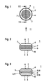
Fig. 1 ein piezoelektrisches Bauteil entsprechend einem ersten Ausführungsbeispiel der Erfindung in einer schematischen Darstellung; -
Fig. 2 das inFig. 1 dargestellte piezoelektrische Bauteil gemäß dem ersten Ausführungsbeispiel der Erfindung in einer schematischen Darstellung aus der inFig. 1 mit II bezeichneten Blickrichtung; -
Fig. 3 das inFig. 1 dargestellte piezoelektrische Bauteil gemäß dem ersten Ausführungsbeispiel in einer schematischen Schnittdarstellung entlang der inFig. 1 mit III bezeichneten Schnittlinie; -
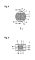
Fig. 4 ein piezoelektrisches Bauteil entsprechend einem zweiten Ausführungsbeispiel der Erfindung in einer schematischen Darstellung; -
Fig. 5 das inFig. 4 dargestellte piezoelektrische Bauteil gemäß dem zweiten Ausführungsbeispiel der Erfindung in einer schematischen Darstellung aus der inFig. 4 mit V bezeichneten Blickrichtung; -
Fig. 6 ein piezoelektrisches Bauteil entsprechend einem dritten Ausführungsbeispiel der Erfindung in einer schematischen Darstellung; -
Fig. 7 das inFig. 6 dargestellte piezoelektrische Bauteil gemäß dem dritten Ausführungsbeispiel der Erfindung in einer schematischen Schnittdarstellung entlang der inFig. 6 mit VII bezeichneten Schnittlinie; -
Fig. 8 ein Prozessflussdiagramm zur Erläuterung eines Verfahrens zur Herstellung des piezoelektrischen Bauteils gemäß dem ersten Ausführungsbeispiel entsprechend einer möglichen Ausgestaltung und -
Fig. 9 ein Prozessflussdiagramm zur Erläuterung eines Verfahrens zur Herstellung des piezoelektrischen Bauteils gemäß dem zweiten Ausführungsbeispiel entsprechend einer möglichen Ausgestaltung der Erfindung.
-
Fig. 1 a piezoelectric component according to a first embodiment of the invention in a schematic representation; -
Fig. 2 this inFig. 1 illustrated piezoelectric component according to the first embodiment of the invention in a schematic representation of the inFig. 1 with II designated viewing direction; -
Fig. 3 this inFig. 1 illustrated piezoelectric component according to the first embodiment in a schematic sectional view along in FIGFig. 1 with III designated cutting line; -
Fig. 4 a piezoelectric component according to a second embodiment of the invention in a schematic representation; -
Fig. 5 this inFig. 4 illustrated piezoelectric component according to the second embodiment of the invention in a schematic representation of the inFig. 4 V direction; -
Fig. 6 a piezoelectric component according to a third embodiment of the invention in a schematic representation; -
Fig. 7 this inFig. 6 shown piezoelectric component according to the third embodiment of the invention in a schematic sectional view along in FIGFig. 6 with VII designated section line; -
Fig. 8 a process flow diagram for explaining a method of manufacturing the piezoelectric component according to the first embodiment according to a possible embodiment and -
Fig. 9 a process flow diagram for explaining a method of manufacturing the piezoelectric component according to the second embodiment according to a possible embodiment of the invention.
Das piezoelektrische Bauteil 1 weist einen Grundkörper 2 auf. Der Grundkörper 2 weist eine Außenseite 3 auf, die in diesem Ausführungsbeispiel als zylindermantelförmige Außenseite 3 ausgestaltet ist. Ferner ist an dem Grundkörper 2 eine Abtragung 4 vorgesehen, die durch eine Fase 4 gebildet ist.The
An der Außenseite 3 des Grundkörpers 2 ist eine Außenmetallisierung 5 vorgesehen, die sich in diesem Ausführungsbeispiel über die gesamte Außenseite 3 des Grundkörpers 2 erstreckt.On the
Ferner ist an einer Stirnseite 6 (
Die Fase 4 ist ringförmig ausgestaltet und umschließt die Stirnseite 6. Ferner ist eine weitere Abtragung 10 vorgesehen, die durch eine Fase 10 gebildet ist. Die Fase 10 ist im Bereich der weiteren Stirnseite 8 vorgesehen und umschließt die weitere Stirnseite 8 ringförmig. Durch die Fase 10 ist die weitere stirnseitige Außenelektrode 9 von der Außenmetallisierung 5 getrennt.The
Außerdem sind in diesem Ausführungsbeispiel im Bereich der Stirnseite 6 beziehungsweise der stirnseitigen Außenelektrode 7 Abtragungen 4, 21 vorgesehen, die durch Fasen 4, 21 gebildet sind. Hierbei erstreckt sich die Fase 4 an der Stirnseite 6 entlang der seitlichen Abflachung 18. Die Fase 21 erstreckt sich an der Stirnseite 6 entlang der seitlichen Abflachung 19.In addition, in this embodiment in the region of the
Eine schematische Schnittdarstellung des in
Eine Seitenansicht aus der in
In den Schritten S3, S4, S5 ist auf der linken Seite jeweils eine Draufsicht auf den Grundkörper 2 dargestellt, wie es der in
Im Schritt S1 wird als Ausgangsmaterial der stangenförmige Block 30 genutzt, der als Halbzeug vorbereitet sein kann. Der stangenförmige Block 30 weist eine Vielzahl von keramischen Schichten 15, 16, 32, 33, 34, 35, 36 und eine Vielzahl von zwischen den keramischen Schichten 15, 16, 32 bis 36 angeordneten innen liegenden Elektrodenschichten 17, 37, 38, 39, 40, 41 auf. Die Außenseite 3 des stangenförmigen Blocks 30 ist in diesem Ausführungsbeispiel zylindermantelförmig ausgestaltet. Der stangenförmige Block 30 ist hierbei zylinderförmig ausgestaltet.In step S1, the rod-shaped
Im Schritt S2, der auf den Schritt S1 folgt, wird die Außenseite 3 vollständig mit einer Außenmetallisierung 5 versehen. Die Außenmetallisierung 5 erstreckt sich somit entlang der Längsachse 31 über den gesamten stangenförmigen Block 30, wenn das Aufbringen der Außenmetallisierung 5 abgeschlossen ist. Anschließend wird der stangenförmige Block 30 an Trennlinien 42 bis 48 aufgetrennt. Bei den Trennlinien 42 bis 48 kann es sich insbesondere um Schnittlinien 42 bis 48 handeln. Insbesondere kann beispielsweise mit einer Diamantsäge eine Vereinzelung des stangenförmigen Blocks 30 in einzelne Scheiben mit jeweils zwei oder mehr keramischen Schichten 15, 16 erfolgen, die anschließend durch Schleifen stirnseitig nachbearbeitet werden können. Im Schritt S3 ist eine dieser Scheiben in Form des Grundkörpers 2 dargestellt. Hierbei sind ebene Stirnseiten 6, 8 gebildet, wobei die innen liegende Elektrodenschicht 17 möglichst mittig zwischen den Stirnseiten 6, 8 angeordnet ist. Dies ist durch eine geeignete Wahl der Schnittlinien 45, 46 erzielbar. Aufgrund der im Schritt S2 über die gesamte Außenseite 3 des stangenförmigen Blocks 30 aufgebrachte Außenmetallisierung 5 ist auch die Außenseite 3 des Grundkörpers 2 zunächst vollständig mit der Außenmetallisierung 5 versehen. Die Stirnseiten 6, 8 liegen noch frei.In step S2, which follows step S1, the
Im Schritt S4, der auf den Schritt S3 folgt, werden die Fasen 4, 10 an dem Grundkörper 2 im Bereich der Stirnseiten 6, 8 ausgestaltet.In step S4, which follows step S3, the
Im Schritt S5, der auf den Schritt S4 folgt, werden an den Stirnseiten 6, 8 stirnseitige Außenelektroden 7, 9 angebracht. Die Außenmetallisierung 5 ist nun einerseits durch die Fase 4 von der stirnseitigen Außenelektrode 7 und andererseits durch die Fase 10 von der stirnseitigen Außenelektrode 9 getrennt.In step S5 following the step S4, frontal
Nach dem Abschluss des Schrittes S5 ist das piezoelektrische Bauteil 1 hergestellt.After the completion of step S5, the
Der stangenförmige Block 30 wird vorzugsweise so hergestellt, dass die innen liegenden Elektrodenschichten 17, 37 bis 41 entlang der Längsachse 31 äquidistant voneinander beabstandet sind. Entsprechend werden dann die Trennlinien 42 bis 48 äquidistant zueinander gelegt. Vorzugsweise befinden sich die Trennlinien 43 bis 47 dann jeweils in der Mitte zwischen benachbarten innen liegenden Elektrodenschichten 17, 37 bis 41. Die äußersten Trennlinien 42, 48 sind in ihrer Lage dann aufgrund der vorgegebenen Äquidistanz bestimmt. Hierdurch werden gleich große Grundkörper 2 abgetrennt, bei denen die innen liegenden Elektrodenschichten 17, 37 bis 41 jeweils zwischen den entsprechenden Stirnseiten 6, 8 liegen.The rod-shaped
Bei einer abgewandelten Ausgestaltung kann die anhand des Schrittes S5 beschriebene Metallisierung der Stirnseiten 6, 8 vor dem Schritt S4 durchgeführt werden, in dem die Fasen 4, 10 an dem Grundkörper 2 ausgestaltet werden.In a modified embodiment, the metallization of the end faces 6, 8 described with reference to step S5 can be carried out before step S4, in which the
Im Schritt S11 wird der stangenförmige Block 30 als Halbzeug hergestellt. Hierbei ist ein Schichten der Vielzahl von keramischen Schichten 15, 16, 32 bis 36 und Elektrodenschichten 17, 37 bis 41 zu dem Block 30 möglich. Der stangenförmige Block 30 wird hierbei vorzugsweise als keramische Mehrschichtstruktur hergestellt. Dies kann durch Stapeln und Laminieren von geeigneten Grünfolien realisiert werden, wobei nach einer gewissen Anzahl von Grünfolien jeweils eine Innenelektrodenpaste für die jeweilige innen liegende Elektrodenschicht 17, 37 bis 41 durch Bedrucken aufgebracht wird. Die so hergestellten stangenförmigen Blöcke 30 können dann entbindert und gesintert werden. Somit kann sich die Herstellung teilweise an eine konventionelle Verfahrensweise anlehnen, bei der piezokeramisches Material in Form von stabförmigen Halbzeugen zum Einsatz kommt. Jedoch weist der im Schritt S11 hergestellte stangenförmige Block 30 bereits die innen liegenden Elektrodenschichten 17, 37 bis 41 in definierten Abständen auf. Im Schritt S12, der auf den Schritt S11 folgt, werden an dem stangenförmigen Block 30 seitliche Abflachungen 18, 19 ausgestaltet. Dies kann beispielsweise durch Beschleifen des stangenförmigen Blocks 30 erfolgen. Hierbei werden die seitlichen Abflachungen 18, 19 entlang der Längsachse 31 an dem gesamten stangenförmigen Block 30 ausgestaltet.In step S11, the bar-shaped
Im Schritt S13, der auf den Schritt S12 folgt, wird zunächst auf den seitlichen Abflachungen 18, 19 jeweils die zugeordnete Außenmetallisierung 5, 20 angebracht. Der übrige Teil der Außenseite 3 bleibt hierbei frei.In step S13, which follows step S12, the associated
Anschließend wird im Schritt S13 eine Vereinzelung des stangenförmigen Blocks 30 durch eine Diamantsäge oder dergleichen ausgeführt. Hierbei erfolgt die Vereinzelung entlang von Trennlinien 42 bis 48. Im Unterschied zu dem anhand der
Im Schritt S14 wird der einzelne Grundkörper 2 mit den Außenmetallisierungen 5, 20 aus den mehreren vereinzelten Scheiben des stangenförmigen Blocks 30 gewählt.In step S14, the
Im Schritt S15, der auf den Schritt S14 folgt, werden die an den Stirnseiten 6, 8 vorgesehenen Kanten zwischen den metallisierten seitlichen Abflachungen 18, 19 und den Stirnseiten 6, 8 mit insgesamt vier Fasen 4, 10, 21, 22 versehen. Durch die Fasen 4, 10, 21, 22 sind Abstände zwischen den Außenmetallisierungen 5, 20 und den Stirnseiten 6, 8 gebildet.In step S15 following step S14, the edges provided on the end faces 6, 8 between the metallized
Im Schritt S16, der auf den Schritt S15 folgt, werden die Stirnseiten 6, 8 mit stirnseitigen Außenelektroden 7, 9 versehen. Durch die Fasen 4, 10, 21, 22 ist eine elektrische Isolierung zwischen der Außenmetallisierung 5, der weiteren Außenmetallisierung 20, der stirnseitigen Außenelektrode 7 und der stirnseitigen Außenelektrode 9 gewährleistet. Somit können beispielsweise die stirnseitigen Außenelektroden 7, 9 auf Masse gelegt werden, während die Außenmetallisierungen 5, 20 zum Abgreifen eines elektrischen Signals beziehungsweise zum Anlegen einer elektrischen Spannung gegenüber Masse dienen.In step S16 following the step S15, the end faces 6, 8 are provided with front-side
Bei einer abgewandelten Ausgestaltung kann der Schritt S16, in dem die stirnseitigen Außenelektroden 7, 9 aufgebracht werden, auch bereits vor dem Schritt S15 ausgeführt werden.In a modified embodiment, the step S16, in which the front-side
Einsatzmöglichkeiten des piezoelektrischen Bauteils 1 in möglicherweise entsprechend abgewandelten Ausgestaltungen sind Mehrlagen-Sensoren, Mehrlagen-Aktoren oder andere funktionskeramische Bauteile 1. Insbesondere ist ein Einsatz auch bei Druck- und Ultraschallanwendungen möglich.Possible applications of the
Die Erfindung ist nicht auf die beschriebenen Ausführungsbeispiele beschränkt.The invention is not limited to the described embodiments.
Claims (10)
dadurch gekennzeichnet,
dass auf einer weiteren Stirnseite (8) des Grundkörpers (2), die von der Stirnseite (6) abgewandt ist, eine Metallisierung (9) aufgebracht ist, die eine weitere stirnseitige Außenelektrode (9) bildet, und dass der Grundkörper (2) eine weitere Abtragung (10) aufweist, die die Außenmetallisierung (5) von der weiteren stirnseitigen Außenelektrode (9) trennt.Piezoelectric component according to claim 1,
characterized,
that on a further front side (8) of the base body (2) facing away from the end face (6), a metallization (9) is applied, which forms a further end-side external electrode (9), and that the base body (2) a further removal (10), which separates the outer metallization (5) from the further front outer electrode (9).
dadurch gekennzeichnet,
dass die Abtragung (4) als Fase (4) ausgestaltet ist, die an der Stirnseite (6) des Grundkörpers (2) vorgesehen ist, und/oder dass die weitere Abtragung (10) als Fase (10) ausgestaltet ist, die an der weiteren Stirnseite (8) des Grundkörpers (2) vorgesehen ist.Piezoelectric component according to claim 2,
characterized,
in that the ablation (4) is configured as a chamfer (4) which is provided on the end face (6) of the main body (2), and / or in that the further ablation (10) is designed as a chamfer (10) which abuts on the another end face (8) of the base body (2) is provided.
dadurch gekennzeichnet,
dass der Grundkörper (2) auf einer zylinderförmigen Ausgestaltung basiert, dass die Außenmetallisierung (5) einheitlich auf eine zylindermantelförmige Außenseite (3) des Grundkörpers (2) aufgebracht ist und dass die Fase (4), die an der Stirnseite (6) des Grundkörpers (2) vorgesehen ist, die Stirnseite (6) des Grundkörpers (2) ringförmig umschließt und/oder dass die Fase (10), die an der weiteren Stirnseite (8) des Grundkörpers (2) vorgesehen ist, die weitere Stirnseite (8) des Grundkörpers (2) ringförmig umschließt.Piezoelectric component according to claim 3,
characterized,
in that the base body (2) is based on a cylindrical configuration, that the outer metallization (5) is uniformly applied to a cylinder jacket-shaped outer side (3) of the main body (2) and that the chamfer (4) is fixed to the front side (6) of the main body (2) is provided, the end face (6) of the base body (2) surrounds annular and / or that the chamfer (10) which is provided on the further end face (8) of the base body (2), the further end face (8) of the main body (2) surrounds annular.
dadurch gekennzeichnet,
dass der Grundkörper (2) auf einer zylinderförmigen Ausgestaltung mit zumindest einer seitlichen Abflachung (18, 19) an der Außenseite (3) basiert, dass die Außenmetallisierung (5, 20) auf der seitlichen Abflachung (18, 19) des Grundkörpers (2) aufgebracht ist und dass die Fase (4, 21), die an der Stirnseite (6) des Grundkörpers (2) vorgesehen ist, an der Stirnseite (6) geradlinig entlang der seitlichen Abflachung (18, 19) des Grundkörpers (2) verläuft und/oder dass die Fase (10, 22), die an der weiteren Stirnseite (8) des Grundkörpers (2) vorgesehen ist, an der weiteren Stirnseite (8) geradlinig entlang der seitlichen Abflachung (18, 19) des Grundkörpers (2) verläuft.Piezoelectric component according to claim 3,
characterized,
in that the base body (2) is based on a cylindrical configuration with at least one lateral flattening (18, 19) on the outer side (3), that the outer metallization (5, 20) on the lateral flattening (18, 19) of the base body (2). is applied and that the chamfer (4, 21) which is provided on the end face (6) of the base body (2) on the end face (6) extends rectilinearly along the lateral flattening (18, 19) of the base body (2) and / or that the chamfer (10, 22), which is provided on the further end face (8) of the base body (2) on the further end face (8) extends rectilinearly along the lateral flattening (18, 19) of the base body (2) ,
dadurch gekennzeichnet,
dass die Außenmetallisierung (5) einheitlich auf die gesamte Außenseite (3) des stangenförmigen Blocks (30) aufgebracht wird.Method according to claim 6,
characterized,
in that the outer metallization (5) is uniformly applied to the entire outer side (3) of the rod-shaped block (30).
dadurch gekennzeichnet,
dass der stangenförmige Block (30) mit einer zylindermantelförmigen Außenseite (3) ausgebildet wird, dass die Abtragung (4) durch eine Fase (4), die die Stirnseite (6) des Grundkörpers (2) ringförmig umschließt, an der Stirnseite (6) des Grundkörpers (2) ausgestaltet wird und dass die innerhalb der Fase (4) verbleibende Stirnseite (6) des Grundkörpers (2) mit der Metallisierung (7) für die stirnseitige Außenelektrode (7) beschichtet wird.Method according to claim 7,
characterized,
in that the rod-shaped block (30) is formed with a cylinder-jacket-shaped outer side (3) such that the ablation (4) is formed on the end face (6) by a chamfer (4) which surrounds the end face (6) of the base body (2). of the base body (2) is configured and that within the chamfer (4) remaining end face (6) of the base body (2) with the metallization (7) for the frontal outer electrode (7) is coated.
dadurch gekennzeichnet,
dass an dem stangenförmigen Block (30) eine seitliche Abflachung (18, 19) ausgestaltet wird, die sich entlang einer Längsachse (31) des stangenförmigen Blocks (30) erstreckt, und dass die Außenmetallisierung (5, 20) auf die seitliche Abflachung (18, 19) des stangenförmigen Blocks (30) aufgebracht wird.Method according to claim 6,
characterized,
in that a lateral flattening (18, 19) extending along a longitudinal axis (31) of the bar-shaped block (30) is formed on the bar-shaped block (30), and in that the outer metallization (5, 20) acts on the lateral flattening (18 , 19) of the rod-shaped block (30) is applied.
dadurch gekennzeichnet,
dass die Abtragung (4, 21) durch eine Fase (4, 21), die geradlinig entlang der seitlichen Abflachung (18, 19) des Grundkörpers (2), die sich aus der seitlichen Abflachung (18, 19) des stangenförmigen Blocks (30) ergibt, verläuft, an der Stirnseite (6) des Grundkörpers (2) ausgestaltet wird und dass die neben der Fase (4, 11) verbleibende Stirnseite (6) des Grundkörpers (2) mit der Metallisierung (7) für die stirnseitige Außenelektrode (7) beschichtet wird.Method according to claim 9,
characterized,
that the removal (4, 21) by a chamfer (4, 21), the straight line along the lateral flattening (18, 19) of the base body (2) extending from the lateral flattening (18, 19) (the bar-shaped block 30 ), extends, on the end face (6) of the base body (2) is configured and that in addition to the chamfer (4, 11) remaining end face (6) of the base body (2) with the metallization (7) for the front outer electrode ( 7) is coated.
Applications Claiming Priority (1)
| Application Number | Priority Date | Filing Date | Title |
|---|---|---|---|
| DE102013200243.2A DE102013200243A1 (en) | 2013-01-10 | 2013-01-10 | Piezoelectric component and method for producing a piezoelectric component |
Publications (3)
| Publication Number | Publication Date |
|---|---|
| EP2755248A2 true EP2755248A2 (en) | 2014-07-16 |
| EP2755248A3 EP2755248A3 (en) | 2017-09-13 |
| EP2755248B1 EP2755248B1 (en) | 2019-04-10 |
Family
ID=49553606
Family Applications (1)
| Application Number | Title | Priority Date | Filing Date |
|---|---|---|---|
| EP13192314.6A Not-in-force EP2755248B1 (en) | 2013-01-10 | 2013-11-11 | Piezoelectric component and method for producing a piezoelectric component |
Country Status (3)
| Country | Link |
|---|---|
| US (1) | US9453487B2 (en) |
| EP (1) | EP2755248B1 (en) |
| DE (1) | DE102013200243A1 (en) |
Cited By (1)
| Publication number | Priority date | Publication date | Assignee | Title |
|---|---|---|---|---|
| CN110379916A (en) * | 2019-07-05 | 2019-10-25 | 中国科学院物理研究所 | The preparation method of piezo ceramic element |
Families Citing this family (1)
| Publication number | Priority date | Publication date | Assignee | Title |
|---|---|---|---|---|
| CN107636963B (en) * | 2015-06-12 | 2020-07-28 | 株式会社村田制作所 | Quartz piece and quartz resonator |
Citations (1)
| Publication number | Priority date | Publication date | Assignee | Title |
|---|---|---|---|---|
| DE102010000827A1 (en) | 2010-01-12 | 2011-07-14 | Robert Bosch GmbH, 70469 | fuel injector |
Family Cites Families (13)
| Publication number | Priority date | Publication date | Assignee | Title |
|---|---|---|---|---|
| WO2000038252A1 (en) * | 1998-12-18 | 2000-06-29 | Denso Corporation | Piezoelectric multilayer body |
| JP2000332313A (en) * | 1999-05-21 | 2000-11-30 | Matsushita Electric Ind Co Ltd | Thin film piezoelectric bimorph element and application thereof |
| EP1277243B1 (en) * | 2000-04-27 | 2012-01-04 | Endress + Hauser GmbH + Co. KG | Piezo-ceramic multilayer component for measuring instruments and method for the production thereof |
| AU2001255845A1 (en) * | 2000-07-28 | 2002-02-13 | The Penn State Research Foundation | A process for fabricating hollow electroactive devices |
| JP2002314156A (en) * | 2001-04-12 | 2002-10-25 | Denso Corp | Piezoelectric element |
| US6859116B2 (en) * | 2001-07-30 | 2005-02-22 | Kyocera Corporation | Piezoelectric resonator |
| JP2003197992A (en) * | 2001-12-26 | 2003-07-11 | Murata Mfg Co Ltd | Laminated type piezoelectric body and its manufacturing method |
| DE102005046118A1 (en) * | 2005-09-27 | 2007-03-29 | Robert Bosch Gmbh | Piezoelectric actuator for use as adjusting unit in fuel injection system for e.g. direct injection internal combustion engine, protective resistors between connection and layer electrodes, and formed by metallic layers |
| DE102006018034A1 (en) * | 2006-04-19 | 2007-10-31 | Robert Bosch Gmbh | Piezoactuator and method for its production |
| JP5521652B2 (en) * | 2009-03-18 | 2014-06-18 | 株式会社リコー | Piezoelectric actuator, liquid discharge head, and image forming apparatus |
| DE102009029521A1 (en) * | 2009-09-17 | 2011-03-24 | Robert Bosch Gmbh | Piezoelectric actuator for actuating selector valve in fuel injection system to control fuel injection in internal combustion engine of motor vehicle, has contact surface between partial area of electrode windings and metallization layer |
| JP5914355B2 (en) * | 2010-11-30 | 2016-05-11 | オリンパス株式会社 | Piezoelectric actuator |
| JP5891935B2 (en) * | 2011-07-04 | 2016-03-23 | 株式会社大真空 | Quartz diaphragm and quartz crystal resonator using the quartz diaphragm |
-
2013
- 2013-01-10 DE DE102013200243.2A patent/DE102013200243A1/en not_active Withdrawn
- 2013-11-11 EP EP13192314.6A patent/EP2755248B1/en not_active Not-in-force
-
2014
- 2014-01-10 US US14/152,044 patent/US9453487B2/en not_active Expired - Fee Related
Patent Citations (1)
| Publication number | Priority date | Publication date | Assignee | Title |
|---|---|---|---|---|
| DE102010000827A1 (en) | 2010-01-12 | 2011-07-14 | Robert Bosch GmbH, 70469 | fuel injector |
Cited By (1)
| Publication number | Priority date | Publication date | Assignee | Title |
|---|---|---|---|---|
| CN110379916A (en) * | 2019-07-05 | 2019-10-25 | 中国科学院物理研究所 | The preparation method of piezo ceramic element |
Also Published As
| Publication number | Publication date |
|---|---|
| US20140191621A1 (en) | 2014-07-10 |
| US9453487B2 (en) | 2016-09-27 |
| DE102013200243A1 (en) | 2014-07-10 |
| EP2755248B1 (en) | 2019-04-10 |
| EP2755248A3 (en) | 2017-09-13 |
Similar Documents
| Publication | Publication Date | Title |
|---|---|---|
| EP1908131B1 (en) | Method for producing a monolithic piezo actuator with stack elements, monilithic piezo actuator with stack elements, and use of the piezo actuator | |
| DE102006003070B3 (en) | Electrical contacting of stack of electronic components e.g. for piezo actuator, by covering insulating layers with electrically conductive material which also fills contact holes | |
| EP1008193B1 (en) | Method for the production of piezoelectric actuators and a piezoelectric actuator | |
| DE19860001C2 (en) | Piezoelectric component, method for its production and use of such a component | |
| WO2006103154A1 (en) | Monolithic piezoelectric component comprising a mechanical uncoupling, method for producing same and use thereof | |
| EP2755248B1 (en) | Piezoelectric component and method for producing a piezoelectric component | |
| EP2543085B1 (en) | Piezoelectric component | |
| DE102006001656A1 (en) | Fabrication method for monolithic multi-layer piezo-actuator, involves selectively etching back in section of inner electrodes | |
| EP1821351B1 (en) | Method to produce a piezoelectric device | |
| EP1233462B1 (en) | Multilayer actuator with shifted contact areas of internal electrodes having the same polarization to their external electrode | |
| DE102012218755B4 (en) | Method for producing an electronic component as a stack and designed as a stack electronic component | |
| DE102013206933A1 (en) | Modular actuator unit for an injection valve | |
| EP2798679B1 (en) | Piezo-stack with passivation, and a method for the passivation of a piezo-stack | |
| DE102012221084A1 (en) | Fuel pressure sensor of component e.g. fuel injection valve for fuel injection system of internal combustion engine, has electrode element that is arranged between piezoceramic sensor discs arranged in polygon or rectangular shape | |
| DE102006046217B3 (en) | Piezo-stack of ceramic raw material i.e. lead zirconate, manufacturing method, involves inserting stack in matrix-shaped arranged saw patterns in supporting device, and removing and projecting corners of inserted stacks from patterns | |
| WO2009156202A1 (en) | Method for the production of a stacked piezoactuator and piezoactuator | |
| EP3036431B1 (en) | Piezo actuator for a fuel injector, and fuel injector | |
| DE102017108384A1 (en) | Multi-layer component and method for producing a multilayer component | |
| DE102012211103A1 (en) | Piezo element has internal electrode layer arranged between two adjacent piezoceramic layer elements, while piezo element comprises cross-section in one plane of electrode layer than in planes by adjacent piezoceramic layer elements | |
| DE102015217334B3 (en) | Method for producing a stacked multilayer actuator | |
| WO2003073524A2 (en) | Piezostack and method for producing a piezostack | |
| DD293689A5 (en) | LAMINATED CERAMIC ARRANGEMENT AND METHOD OF MANUFACTURING THE SAME | |
| DE102009020238A1 (en) | Piezo actuator with electrical contacting pins | |
| DE102010008775A1 (en) | Piezoelectric multilayer component and method for producing a piezoelectric multilayer component | |
| WO2012031942A1 (en) | Method for producing piezoelectric actuators from a material block |
Legal Events
| Date | Code | Title | Description |
|---|---|---|---|
| PUAI | Public reference made under article 153(3) epc to a published international application that has entered the european phase |
Free format text: ORIGINAL CODE: 0009012 |
|
| 17P | Request for examination filed |
Effective date: 20131111 |
|
| AK | Designated contracting states |
Kind code of ref document: A2 Designated state(s): AL AT BE BG CH CY CZ DE DK EE ES FI FR GB GR HR HU IE IS IT LI LT LU LV MC MK MT NL NO PL PT RO RS SE SI SK SM TR |
|
| AX | Request for extension of the european patent |
Extension state: BA ME |
|
| PUAL | Search report despatched |
Free format text: ORIGINAL CODE: 0009013 |
|
| AK | Designated contracting states |
Kind code of ref document: A3 Designated state(s): AL AT BE BG CH CY CZ DE DK EE ES FI FR GB GR HR HU IE IS IT LI LT LU LV MC MK MT NL NO PL PT RO RS SE SI SK SM TR |
|
| AX | Request for extension of the european patent |
Extension state: BA ME |
|
| RIC1 | Information provided on ipc code assigned before grant |
Ipc: H01L 41/29 20130101ALI20170804BHEP Ipc: H01L 41/338 20130101ALI20170804BHEP Ipc: H01L 41/113 20060101ALN20170804BHEP Ipc: H01L 41/293 20130101ALI20170804BHEP Ipc: H01L 41/09 20060101ALN20170804BHEP Ipc: H01L 41/083 20060101AFI20170804BHEP Ipc: H01L 41/047 20060101ALI20170804BHEP Ipc: H01L 41/273 20130101ALI20170804BHEP |
|
| STAA | Information on the status of an ep patent application or granted ep patent |
Free format text: STATUS: REQUEST FOR EXAMINATION WAS MADE |
|
| R17P | Request for examination filed (corrected) |
Effective date: 20180313 |
|
| RBV | Designated contracting states (corrected) |
Designated state(s): AL AT BE BG CH CY CZ DE DK EE ES FI FR GB GR HR HU IE IS IT LI LT LU LV MC MK MT NL NO PL PT RO RS SE SI SK SM TR |
|
| STAA | Information on the status of an ep patent application or granted ep patent |
Free format text: STATUS: EXAMINATION IS IN PROGRESS |
|
| 17Q | First examination report despatched |
Effective date: 20180517 |
|
| RIC1 | Information provided on ipc code assigned before grant |
Ipc: H01L 41/09 20060101ALN20181009BHEP Ipc: H01L 41/29 20130101ALI20181009BHEP Ipc: H01L 41/273 20130101ALI20181009BHEP Ipc: H01L 41/293 20130101ALI20181009BHEP Ipc: H01L 41/337 20130101ALI20181009BHEP Ipc: H01L 41/083 20060101AFI20181009BHEP Ipc: H01L 41/113 20060101ALN20181009BHEP Ipc: H01L 41/047 20060101ALI20181009BHEP Ipc: H01L 41/338 20130101ALI20181009BHEP |
|
| GRAP | Despatch of communication of intention to grant a patent |
Free format text: ORIGINAL CODE: EPIDOSNIGR1 |
|
| STAA | Information on the status of an ep patent application or granted ep patent |
Free format text: STATUS: GRANT OF PATENT IS INTENDED |
|
| INTG | Intention to grant announced |
Effective date: 20181123 |
|
| GRAS | Grant fee paid |
Free format text: ORIGINAL CODE: EPIDOSNIGR3 |
|
| GRAA | (expected) grant |
Free format text: ORIGINAL CODE: 0009210 |
|
| STAA | Information on the status of an ep patent application or granted ep patent |
Free format text: STATUS: THE PATENT HAS BEEN GRANTED |
|
| AK | Designated contracting states |
Kind code of ref document: B1 Designated state(s): AL AT BE BG CH CY CZ DE DK EE ES FI FR GB GR HR HU IE IS IT LI LT LU LV MC MK MT NL NO PL PT RO RS SE SI SK SM TR |
|
| REG | Reference to a national code |
Ref country code: GB Ref legal event code: FG4D Free format text: NOT ENGLISH |
|
| REG | Reference to a national code |
Ref country code: CH Ref legal event code: EP Ref country code: AT Ref legal event code: REF Ref document number: 1119876 Country of ref document: AT Kind code of ref document: T Effective date: 20190415 |
|
| REG | Reference to a national code |
Ref country code: IE Ref legal event code: FG4D Free format text: LANGUAGE OF EP DOCUMENT: GERMAN |
|
| REG | Reference to a national code |
Ref country code: DE Ref legal event code: R096 Ref document number: 502013012581 Country of ref document: DE |
|
| REG | Reference to a national code |
Ref country code: NL Ref legal event code: MP Effective date: 20190410 |
|
| REG | Reference to a national code |
Ref country code: LT Ref legal event code: MG4D |
|
| PG25 | Lapsed in a contracting state [announced via postgrant information from national office to epo] |
Ref country code: NL Free format text: LAPSE BECAUSE OF FAILURE TO SUBMIT A TRANSLATION OF THE DESCRIPTION OR TO PAY THE FEE WITHIN THE PRESCRIBED TIME-LIMIT Effective date: 20190410 |
|
| PG25 | Lapsed in a contracting state [announced via postgrant information from national office to epo] |
Ref country code: LT Free format text: LAPSE BECAUSE OF FAILURE TO SUBMIT A TRANSLATION OF THE DESCRIPTION OR TO PAY THE FEE WITHIN THE PRESCRIBED TIME-LIMIT Effective date: 20190410 Ref country code: HR Free format text: LAPSE BECAUSE OF FAILURE TO SUBMIT A TRANSLATION OF THE DESCRIPTION OR TO PAY THE FEE WITHIN THE PRESCRIBED TIME-LIMIT Effective date: 20190410 Ref country code: NO Free format text: LAPSE BECAUSE OF FAILURE TO SUBMIT A TRANSLATION OF THE DESCRIPTION OR TO PAY THE FEE WITHIN THE PRESCRIBED TIME-LIMIT Effective date: 20190710 Ref country code: FI Free format text: LAPSE BECAUSE OF FAILURE TO SUBMIT A TRANSLATION OF THE DESCRIPTION OR TO PAY THE FEE WITHIN THE PRESCRIBED TIME-LIMIT Effective date: 20190410 Ref country code: PT Free format text: LAPSE BECAUSE OF FAILURE TO SUBMIT A TRANSLATION OF THE DESCRIPTION OR TO PAY THE FEE WITHIN THE PRESCRIBED TIME-LIMIT Effective date: 20190910 Ref country code: SE Free format text: LAPSE BECAUSE OF FAILURE TO SUBMIT A TRANSLATION OF THE DESCRIPTION OR TO PAY THE FEE WITHIN THE PRESCRIBED TIME-LIMIT Effective date: 20190410 Ref country code: AL Free format text: LAPSE BECAUSE OF FAILURE TO SUBMIT A TRANSLATION OF THE DESCRIPTION OR TO PAY THE FEE WITHIN THE PRESCRIBED TIME-LIMIT Effective date: 20190410 Ref country code: ES Free format text: LAPSE BECAUSE OF FAILURE TO SUBMIT A TRANSLATION OF THE DESCRIPTION OR TO PAY THE FEE WITHIN THE PRESCRIBED TIME-LIMIT Effective date: 20190410 |
|
| PG25 | Lapsed in a contracting state [announced via postgrant information from national office to epo] |
Ref country code: BG Free format text: LAPSE BECAUSE OF FAILURE TO SUBMIT A TRANSLATION OF THE DESCRIPTION OR TO PAY THE FEE WITHIN THE PRESCRIBED TIME-LIMIT Effective date: 20190710 Ref country code: RS Free format text: LAPSE BECAUSE OF FAILURE TO SUBMIT A TRANSLATION OF THE DESCRIPTION OR TO PAY THE FEE WITHIN THE PRESCRIBED TIME-LIMIT Effective date: 20190410 Ref country code: LV Free format text: LAPSE BECAUSE OF FAILURE TO SUBMIT A TRANSLATION OF THE DESCRIPTION OR TO PAY THE FEE WITHIN THE PRESCRIBED TIME-LIMIT Effective date: 20190410 Ref country code: PL Free format text: LAPSE BECAUSE OF FAILURE TO SUBMIT A TRANSLATION OF THE DESCRIPTION OR TO PAY THE FEE WITHIN THE PRESCRIBED TIME-LIMIT Effective date: 20190410 Ref country code: GR Free format text: LAPSE BECAUSE OF FAILURE TO SUBMIT A TRANSLATION OF THE DESCRIPTION OR TO PAY THE FEE WITHIN THE PRESCRIBED TIME-LIMIT Effective date: 20190711 |
|
| PG25 | Lapsed in a contracting state [announced via postgrant information from national office to epo] |
Ref country code: IS Free format text: LAPSE BECAUSE OF FAILURE TO SUBMIT A TRANSLATION OF THE DESCRIPTION OR TO PAY THE FEE WITHIN THE PRESCRIBED TIME-LIMIT Effective date: 20190810 |
|
| REG | Reference to a national code |
Ref country code: DE Ref legal event code: R097 Ref document number: 502013012581 Country of ref document: DE |
|
| PG25 | Lapsed in a contracting state [announced via postgrant information from national office to epo] |
Ref country code: EE Free format text: LAPSE BECAUSE OF FAILURE TO SUBMIT A TRANSLATION OF THE DESCRIPTION OR TO PAY THE FEE WITHIN THE PRESCRIBED TIME-LIMIT Effective date: 20190410 Ref country code: DK Free format text: LAPSE BECAUSE OF FAILURE TO SUBMIT A TRANSLATION OF THE DESCRIPTION OR TO PAY THE FEE WITHIN THE PRESCRIBED TIME-LIMIT Effective date: 20190410 Ref country code: CZ Free format text: LAPSE BECAUSE OF FAILURE TO SUBMIT A TRANSLATION OF THE DESCRIPTION OR TO PAY THE FEE WITHIN THE PRESCRIBED TIME-LIMIT Effective date: 20190410 Ref country code: RO Free format text: LAPSE BECAUSE OF FAILURE TO SUBMIT A TRANSLATION OF THE DESCRIPTION OR TO PAY THE FEE WITHIN THE PRESCRIBED TIME-LIMIT Effective date: 20190410 Ref country code: SK Free format text: LAPSE BECAUSE OF FAILURE TO SUBMIT A TRANSLATION OF THE DESCRIPTION OR TO PAY THE FEE WITHIN THE PRESCRIBED TIME-LIMIT Effective date: 20190410 |
|
| PLBE | No opposition filed within time limit |
Free format text: ORIGINAL CODE: 0009261 |
|
| STAA | Information on the status of an ep patent application or granted ep patent |
Free format text: STATUS: NO OPPOSITION FILED WITHIN TIME LIMIT |
|
| PG25 | Lapsed in a contracting state [announced via postgrant information from national office to epo] |
Ref country code: SM Free format text: LAPSE BECAUSE OF FAILURE TO SUBMIT A TRANSLATION OF THE DESCRIPTION OR TO PAY THE FEE WITHIN THE PRESCRIBED TIME-LIMIT Effective date: 20190410 Ref country code: IT Free format text: LAPSE BECAUSE OF FAILURE TO SUBMIT A TRANSLATION OF THE DESCRIPTION OR TO PAY THE FEE WITHIN THE PRESCRIBED TIME-LIMIT Effective date: 20190410 |
|
| PGFP | Annual fee paid to national office [announced via postgrant information from national office to epo] |
Ref country code: FR Payment date: 20191121 Year of fee payment: 7 |
|
| 26N | No opposition filed |
Effective date: 20200113 |
|
| PG25 | Lapsed in a contracting state [announced via postgrant information from national office to epo] |
Ref country code: TR Free format text: LAPSE BECAUSE OF FAILURE TO SUBMIT A TRANSLATION OF THE DESCRIPTION OR TO PAY THE FEE WITHIN THE PRESCRIBED TIME-LIMIT Effective date: 20190410 |
|
| PGFP | Annual fee paid to national office [announced via postgrant information from national office to epo] |
Ref country code: DE Payment date: 20200124 Year of fee payment: 7 |
|
| PG25 | Lapsed in a contracting state [announced via postgrant information from national office to epo] |
Ref country code: SI Free format text: LAPSE BECAUSE OF FAILURE TO SUBMIT A TRANSLATION OF THE DESCRIPTION OR TO PAY THE FEE WITHIN THE PRESCRIBED TIME-LIMIT Effective date: 20190410 |
|
| REG | Reference to a national code |
Ref country code: CH Ref legal event code: PL |
|
| PG25 | Lapsed in a contracting state [announced via postgrant information from national office to epo] |
Ref country code: CH Free format text: LAPSE BECAUSE OF NON-PAYMENT OF DUE FEES Effective date: 20191130 Ref country code: LU Free format text: LAPSE BECAUSE OF NON-PAYMENT OF DUE FEES Effective date: 20191111 Ref country code: MC Free format text: LAPSE BECAUSE OF FAILURE TO SUBMIT A TRANSLATION OF THE DESCRIPTION OR TO PAY THE FEE WITHIN THE PRESCRIBED TIME-LIMIT Effective date: 20190410 Ref country code: LI Free format text: LAPSE BECAUSE OF NON-PAYMENT OF DUE FEES Effective date: 20191130 |
|
| REG | Reference to a national code |
Ref country code: BE Ref legal event code: MM Effective date: 20191130 |
|
| GBPC | Gb: european patent ceased through non-payment of renewal fee |
Effective date: 20191111 |
|
| PG25 | Lapsed in a contracting state [announced via postgrant information from national office to epo] |
Ref country code: IE Free format text: LAPSE BECAUSE OF NON-PAYMENT OF DUE FEES Effective date: 20191111 Ref country code: GB Free format text: LAPSE BECAUSE OF NON-PAYMENT OF DUE FEES Effective date: 20191111 |
|
| PG25 | Lapsed in a contracting state [announced via postgrant information from national office to epo] |
Ref country code: BE Free format text: LAPSE BECAUSE OF NON-PAYMENT OF DUE FEES Effective date: 20191130 |
|
| REG | Reference to a national code |
Ref country code: AT Ref legal event code: MM01 Ref document number: 1119876 Country of ref document: AT Kind code of ref document: T Effective date: 20191111 |
|
| PG25 | Lapsed in a contracting state [announced via postgrant information from national office to epo] |
Ref country code: AT Free format text: LAPSE BECAUSE OF NON-PAYMENT OF DUE FEES Effective date: 20191111 |
|
| PG25 | Lapsed in a contracting state [announced via postgrant information from national office to epo] |
Ref country code: CY Free format text: LAPSE BECAUSE OF FAILURE TO SUBMIT A TRANSLATION OF THE DESCRIPTION OR TO PAY THE FEE WITHIN THE PRESCRIBED TIME-LIMIT Effective date: 20190410 |
|
| REG | Reference to a national code |
Ref country code: DE Ref legal event code: R119 Ref document number: 502013012581 Country of ref document: DE |
|
| PG25 | Lapsed in a contracting state [announced via postgrant information from national office to epo] |
Ref country code: HU Free format text: LAPSE BECAUSE OF FAILURE TO SUBMIT A TRANSLATION OF THE DESCRIPTION OR TO PAY THE FEE WITHIN THE PRESCRIBED TIME-LIMIT; INVALID AB INITIO Effective date: 20131111 Ref country code: MT Free format text: LAPSE BECAUSE OF FAILURE TO SUBMIT A TRANSLATION OF THE DESCRIPTION OR TO PAY THE FEE WITHIN THE PRESCRIBED TIME-LIMIT Effective date: 20190410 |
|
| PG25 | Lapsed in a contracting state [announced via postgrant information from national office to epo] |
Ref country code: FR Free format text: LAPSE BECAUSE OF NON-PAYMENT OF DUE FEES Effective date: 20201130 |
|
| PG25 | Lapsed in a contracting state [announced via postgrant information from national office to epo] |
Ref country code: DE Free format text: LAPSE BECAUSE OF NON-PAYMENT OF DUE FEES Effective date: 20210601 |
|
| PG25 | Lapsed in a contracting state [announced via postgrant information from national office to epo] |
Ref country code: MK Free format text: LAPSE BECAUSE OF FAILURE TO SUBMIT A TRANSLATION OF THE DESCRIPTION OR TO PAY THE FEE WITHIN THE PRESCRIBED TIME-LIMIT Effective date: 20190410 |