EP2755211B1 - Method and arrangement of crosslinking or vulcanizing an elongate element - Google Patents
Method and arrangement of crosslinking or vulcanizing an elongate element Download PDFInfo
- Publication number
- EP2755211B1 EP2755211B1 EP14150439.9A EP14150439A EP2755211B1 EP 2755211 B1 EP2755211 B1 EP 2755211B1 EP 14150439 A EP14150439 A EP 14150439A EP 2755211 B1 EP2755211 B1 EP 2755211B1
- Authority
- EP
- European Patent Office
- Prior art keywords
- conductor element
- crosslinking
- arrangement
- vulcanizing
- tube
- Prior art date
- Legal status (The legal status is an assumption and is not a legal conclusion. Google has not performed a legal analysis and makes no representation as to the accuracy of the status listed.)
- Revoked
Links
Images

Classifications
-
- B—PERFORMING OPERATIONS; TRANSPORTING
- B29—WORKING OF PLASTICS; WORKING OF SUBSTANCES IN A PLASTIC STATE IN GENERAL
- B29C—SHAPING OR JOINING OF PLASTICS; SHAPING OF MATERIAL IN A PLASTIC STATE, NOT OTHERWISE PROVIDED FOR; AFTER-TREATMENT OF THE SHAPED PRODUCTS, e.g. REPAIRING
- B29C48/00—Extrusion moulding, i.e. expressing the moulding material through a die or nozzle which imparts the desired form; Apparatus therefor
- B29C48/03—Extrusion moulding, i.e. expressing the moulding material through a die or nozzle which imparts the desired form; Apparatus therefor characterised by the shape of the extruded material at extrusion
- B29C48/09—Articles with cross-sections having partially or fully enclosed cavities, e.g. pipes or channels
-
- B—PERFORMING OPERATIONS; TRANSPORTING
- B29—WORKING OF PLASTICS; WORKING OF SUBSTANCES IN A PLASTIC STATE IN GENERAL
- B29C—SHAPING OR JOINING OF PLASTICS; SHAPING OF MATERIAL IN A PLASTIC STATE, NOT OTHERWISE PROVIDED FOR; AFTER-TREATMENT OF THE SHAPED PRODUCTS, e.g. REPAIRING
- B29C35/00—Heating, cooling or curing, e.g. crosslinking or vulcanising; Apparatus therefor
- B29C35/02—Heating or curing, e.g. crosslinking or vulcanizing during moulding, e.g. in a mould
- B29C35/08—Heating or curing, e.g. crosslinking or vulcanizing during moulding, e.g. in a mould by wave energy or particle radiation
- B29C35/10—Heating or curing, e.g. crosslinking or vulcanizing during moulding, e.g. in a mould by wave energy or particle radiation for articles of indefinite length
-
- B—PERFORMING OPERATIONS; TRANSPORTING
- B29—WORKING OF PLASTICS; WORKING OF SUBSTANCES IN A PLASTIC STATE IN GENERAL
- B29C—SHAPING OR JOINING OF PLASTICS; SHAPING OF MATERIAL IN A PLASTIC STATE, NOT OTHERWISE PROVIDED FOR; AFTER-TREATMENT OF THE SHAPED PRODUCTS, e.g. REPAIRING
- B29C35/00—Heating, cooling or curing, e.g. crosslinking or vulcanising; Apparatus therefor
- B29C35/02—Heating or curing, e.g. crosslinking or vulcanizing during moulding, e.g. in a mould
- B29C35/0272—Heating or curing, e.g. crosslinking or vulcanizing during moulding, e.g. in a mould using lost heating elements, i.e. heating means incorporated and remaining in the formed article
-
- B—PERFORMING OPERATIONS; TRANSPORTING
- B29—WORKING OF PLASTICS; WORKING OF SUBSTANCES IN A PLASTIC STATE IN GENERAL
- B29C—SHAPING OR JOINING OF PLASTICS; SHAPING OF MATERIAL IN A PLASTIC STATE, NOT OTHERWISE PROVIDED FOR; AFTER-TREATMENT OF THE SHAPED PRODUCTS, e.g. REPAIRING
- B29C48/00—Extrusion moulding, i.e. expressing the moulding material through a die or nozzle which imparts the desired form; Apparatus therefor
- B29C48/03—Extrusion moulding, i.e. expressing the moulding material through a die or nozzle which imparts the desired form; Apparatus therefor characterised by the shape of the extruded material at extrusion
- B29C48/06—Rod-shaped
-
- B—PERFORMING OPERATIONS; TRANSPORTING
- B29—WORKING OF PLASTICS; WORKING OF SUBSTANCES IN A PLASTIC STATE IN GENERAL
- B29C—SHAPING OR JOINING OF PLASTICS; SHAPING OF MATERIAL IN A PLASTIC STATE, NOT OTHERWISE PROVIDED FOR; AFTER-TREATMENT OF THE SHAPED PRODUCTS, e.g. REPAIRING
- B29C48/00—Extrusion moulding, i.e. expressing the moulding material through a die or nozzle which imparts the desired form; Apparatus therefor
- B29C48/15—Extrusion moulding, i.e. expressing the moulding material through a die or nozzle which imparts the desired form; Apparatus therefor incorporating preformed parts or layers, e.g. extrusion moulding around inserts
- B29C48/154—Coating solid articles, i.e. non-hollow articles
-
- B—PERFORMING OPERATIONS; TRANSPORTING
- B29—WORKING OF PLASTICS; WORKING OF SUBSTANCES IN A PLASTIC STATE IN GENERAL
- B29C—SHAPING OR JOINING OF PLASTICS; SHAPING OF MATERIAL IN A PLASTIC STATE, NOT OTHERWISE PROVIDED FOR; AFTER-TREATMENT OF THE SHAPED PRODUCTS, e.g. REPAIRING
- B29C48/00—Extrusion moulding, i.e. expressing the moulding material through a die or nozzle which imparts the desired form; Apparatus therefor
- B29C48/16—Articles comprising two or more components, e.g. co-extruded layers
- B29C48/18—Articles comprising two or more components, e.g. co-extruded layers the components being layers
- B29C48/19—Articles comprising two or more components, e.g. co-extruded layers the components being layers the layers being joined at their edges
-
- B—PERFORMING OPERATIONS; TRANSPORTING
- B29—WORKING OF PLASTICS; WORKING OF SUBSTANCES IN A PLASTIC STATE IN GENERAL
- B29C—SHAPING OR JOINING OF PLASTICS; SHAPING OF MATERIAL IN A PLASTIC STATE, NOT OTHERWISE PROVIDED FOR; AFTER-TREATMENT OF THE SHAPED PRODUCTS, e.g. REPAIRING
- B29C48/00—Extrusion moulding, i.e. expressing the moulding material through a die or nozzle which imparts the desired form; Apparatus therefor
- B29C48/25—Component parts, details or accessories; Auxiliary operations
- B29C48/88—Thermal treatment of the stream of extruded material, e.g. cooling
- B29C48/91—Heating, e.g. for cross linking
-
- B—PERFORMING OPERATIONS; TRANSPORTING
- B29—WORKING OF PLASTICS; WORKING OF SUBSTANCES IN A PLASTIC STATE IN GENERAL
- B29C—SHAPING OR JOINING OF PLASTICS; SHAPING OF MATERIAL IN A PLASTIC STATE, NOT OTHERWISE PROVIDED FOR; AFTER-TREATMENT OF THE SHAPED PRODUCTS, e.g. REPAIRING
- B29C71/00—After-treatment of articles without altering their shape; Apparatus therefor
- B29C71/02—Thermal after-treatment
-
- H—ELECTRICITY
- H01—ELECTRIC ELEMENTS
- H01B—CABLES; CONDUCTORS; INSULATORS; SELECTION OF MATERIALS FOR THEIR CONDUCTIVE, INSULATING OR DIELECTRIC PROPERTIES
- H01B13/00—Apparatus or processes specially adapted for manufacturing conductors or cables
- H01B13/0016—Apparatus or processes specially adapted for manufacturing conductors or cables for heat treatment
-
- H—ELECTRICITY
- H01—ELECTRIC ELEMENTS
- H01B—CABLES; CONDUCTORS; INSULATORS; SELECTION OF MATERIALS FOR THEIR CONDUCTIVE, INSULATING OR DIELECTRIC PROPERTIES
- H01B13/00—Apparatus or processes specially adapted for manufacturing conductors or cables
- H01B13/06—Insulating conductors or cables
- H01B13/14—Insulating conductors or cables by extrusion
- H01B13/145—Pretreatment or after-treatment
-
- B—PERFORMING OPERATIONS; TRANSPORTING
- B29—WORKING OF PLASTICS; WORKING OF SUBSTANCES IN A PLASTIC STATE IN GENERAL
- B29C—SHAPING OR JOINING OF PLASTICS; SHAPING OF MATERIAL IN A PLASTIC STATE, NOT OTHERWISE PROVIDED FOR; AFTER-TREATMENT OF THE SHAPED PRODUCTS, e.g. REPAIRING
- B29C35/00—Heating, cooling or curing, e.g. crosslinking or vulcanising; Apparatus therefor
- B29C35/02—Heating or curing, e.g. crosslinking or vulcanizing during moulding, e.g. in a mould
- B29C35/08—Heating or curing, e.g. crosslinking or vulcanizing during moulding, e.g. in a mould by wave energy or particle radiation
- B29C35/0805—Heating or curing, e.g. crosslinking or vulcanizing during moulding, e.g. in a mould by wave energy or particle radiation using electromagnetic radiation
- B29C2035/0811—Heating or curing, e.g. crosslinking or vulcanizing during moulding, e.g. in a mould by wave energy or particle radiation using electromagnetic radiation using induction
-
- B—PERFORMING OPERATIONS; TRANSPORTING
- B29—WORKING OF PLASTICS; WORKING OF SUBSTANCES IN A PLASTIC STATE IN GENERAL
- B29C—SHAPING OR JOINING OF PLASTICS; SHAPING OF MATERIAL IN A PLASTIC STATE, NOT OTHERWISE PROVIDED FOR; AFTER-TREATMENT OF THE SHAPED PRODUCTS, e.g. REPAIRING
- B29C48/00—Extrusion moulding, i.e. expressing the moulding material through a die or nozzle which imparts the desired form; Apparatus therefor
- B29C48/25—Component parts, details or accessories; Auxiliary operations
- B29C48/88—Thermal treatment of the stream of extruded material, e.g. cooling
- B29C48/911—Cooling
- B29C48/9135—Cooling of flat articles, e.g. using specially adapted supporting means
Definitions
- the invention relates to a method of crosslinking or vulcanizing an elongate element the method comprising the following steps:
- the invention relates also to an arrangement for crosslinking or vulcanizing an elongate element.
- the present invention deals with a method and arrangement for processing an elongate element.
- the elongate elements are in practice electrical cables, i.e. the present invention relates to manufacturing electrical wires and cables, more specifically cables for High Voltage (HV) and Extremely High Voltage (EHV).
- HV High Voltage
- EHV Extremely High Voltage
- One widely used and well known construction of energy transmission cables for Medium and High Voltage consist of an electrical conductor (Cu or Al), insulated with one or several layers of plastic material, in general polyethylene. This insulation is applied onto the conductor in a per se known extrusion process.
- thermoplastic polymer material is crosslinked.
- One method known in the art used for that purpose is the known peroxide crosslinking process.
- a catalyst peroxide
- thermoplastic material which, under the effect of temperature, will eventually trigger the chemical reaction leading to the crosslinking of the polymer.
- a well-known method to improve the heating/crosslinking process described above is to heat the conductor internally, such that heat diffuses into the insulation also from the inside, and therefore accelerates the crosslinking reaction.
- This internal heating of the conductor is obtained by means of inductively generating eddy currents inside the conductor.
- inductive heating elements have been known and used for a long time. Said inductive heating elements have been used as preheaters upstream of the extrusion head, i.e. before the extrusion head when seen in the direction of the process and as post-heaters downstream of the extrusion head before the vulcanization tube, i.e. after the extrusion head of the extrusion head and before the vulcanization tube, and also along the vulcanization tube.
- CH Patent 644 548 shows a vulcanization tube setup where the cable is heated from the outside by a pressurized gas, and where the core is heated up by inductive heating elements placed along the vulcanization tube.
- EP Patent 1 839 319 B1 describes an inductive heater arrangement placed downstream of the extrusion head, at the beginning of the vulcanization tube.
- EP Patent Application 12185803.9 discloses a setup for inductively heating the cable core prior to the extrusion step, with heaters placed upstream of the extrusion head.
- US 2006/182880 A1 discloses a method of crosslinking an elongate element according to the preamble of claim 1 and an arrangement of crosslinking an elongate element according to the preamble of claim 3.
- the line speed for HV and EHV cores is very slow (in the range 0.2 to 5 m/min) leading to significant residence time in the heating section.
- relatively low heating profile has to be used which means in practice lower line speed.
- the object of the invention is to obtain a method and an arrangement by which the problems of the prior art can be solved. This is obtained with the invention.
- the method of the invention according to claim 1 is characterized in that the method further comprises a step in which after the vulcanization tube the coated conductor element is heated by using inductive heating, and that the step in which the coated conductor element is heated is carried out immediately before the cooling step.
- the arrangement of the invention according to claim 3 is characterized in that the arrangement further comprises an inductive heating device placed after the vulcanization tube for heating the coated conductor element, and that the inductive heating device is placed immediately before the cooling tube.
- An advantage of the invention is in that it solves the problems of the prior art discussed above.
- the invention offers a method and an arrangement by which it is possible considerably to increase the line speed when compared to the prior art technique.
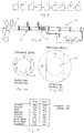
- FIG. 1 shows a principle layout of a vulcanizing extrusion line.
- the vulcanizing extrusion line comprises a payoff 1, a metering capstan or metering caterpillar 2, a preheater 3 for a conductor element, an extrusion group with an extruder head 4, a postheater 5, a vulcanization tube 6, a cooling tube 7, a caterpillar or a capstan 8 and a take-up 9.
- the insulation has to be extruded onto the conductor at a temperature sufficiently low as to avoid premature crosslinking in the extrusion equipment, as this would lead to defects of the insulation.
- the material After the extrusion step, the material has to be heated up at a temperature that is sufficiently high to start and complete the chemical reaction within the shortest possible time.
- the crosslinking reaction is carried out in the vulcanization tube, i.e. a tube surrounding the extruded electrical cable located downstream of the extrusion head, inside which the cable is heated up by radiant and/or convective heat transfer.
- the vulcanization tube i.e. a tube surrounding the extruded electrical cable located downstream of the extrusion head, inside which the cable is heated up by radiant and/or convective heat transfer.
- the heat diffusion in the insulation material is however low, and the polymer layers close to the conductor will take the longest time to increase temperature and undergo the chemical reaction desired.
- a well-known method to improve the heating/crosslinking process is to heat the conductor internally so that heat diffuses into the insulation material extruded also form inside and therefore accelerates the crosslinking reaction.
- This internal heating is materialized by using inductive heating procedure.
- Figure 2 shows a principle layout of a vulcanizing line in which the present invention is used.
- same reference numbers are used to indicate corresponding parts when compared to Figure 1 .
- Figure 2 shows in fact a part of a vulcanizing extrusion line, i.e. only the parts needed to understand the invention are shown. For example pay-off and take-up is not shown on Figure 2 . A person skilled in the art however instantly understands the structure and operation of the line shown in Figure 2 when looking for example Figure 2 together with figure 1 .
- the embodiment shown in Figure 2 has an extrusion group with extruder head 4 and telescopic tube and, vulcanizing tube 6 and cooling tube 7 which in this embodiment is a device with closed-circuit gas cooling.
- Conductor element guided to the extruder head 4 is shown with reference number 12.
- an inductive heating device 10 placed after the vulcanization tube 6 for heating the coated conductor element, i.e. the point in the invention is that the coated conductor element is heated after the vulcanization tube 6 by using inductive heating.
- Figure 2 shows clearly that the inductive device 10 has been placed downstream of the vulcanization tube, i.e. after the vulcanization tube 6 and before cooling tube 7.
- an inductive heating of the conductor is placed downstream of the vulcanization tube 6.
- the crosslinking reaction has progressed sufficiently so that the insulation is partially crosslinked close to the conductor and has increased stiffness or viscosity. Therefore it can be heated up from the conductor by means of inductive heating and thus accelerate completion of the crosslinking without drooping effects.
- inductive heating i.e. by using inductive device 10 as a post heater in the way shown in Figure 2 completes the crosslinking process and also eliminates harmful drooping effects described earlier.
- Figures 3a, 3b and 4 describe said drooping effect.
- Figures 3a and 3b show schematically the difference of gravitational load towards and aside of two different conductors, namely 20 kV ( Fig 3a ) and 150 kV cables (3b) having identical conductor diameters.
- Figures 3a and 3b show said matters in terms of shear stress in the insulation due to gravitational forces.
- Conductor element is shown with reference number 12.
- the still hot plastic material will therefore have a tendency so sag, with loss of centering and roundness of the insulation. This tendency to sag depends on the level of shear stress on one hand, and on the melt strength on the other hand, which in turn decreases with increasing temperatures.
- Figure 4 The matters discussed above and shown in Figures 3a and 3b are shown with numbers in Figure 4 .
- the calculation of Figure 4 as an example compares with numbers the situation of a 20 kV cable to a 150 kV cable of identical conductor element diameter (30,2 mm). It appears that the gravitational load in the 150 kV cable is almost 3 times bigger than in the 20 kV cable. Therefore, if the insulation material close to the conductor element of the 150 kV cable was heated up while still in thermoplastic state, it would sag to an unacceptable extent.
- Figures 5 - 9 show an example in which the situation is compared with the same product with and without the present invention.
- the invention has been described above by using the embodiments described in the Figures.
- the embodiments shown are by no means intended to restrict the invention but the invention may be varied completely freely within the claims.
- the vulcanizing line used can be formed quite freely, i.e. the placements of various steps can vary and there can be additional steps, too.
- the coated conductor element can be also heated before the cooling step if needed, i.e. it is quite possible to provide the vulcanizing line with a pre-heater before the extrusion step.
- Said pre-heater can be for example an inductive heating device etc.
Description
- The invention relates to a method of crosslinking or vulcanizing an elongate element the method comprising the following steps:
- an extrusion step in which a conductor element is coated by a layer of crosslinkable material,
- a step in which a crosslinking reaction is carried out by processing the coated conductor element in a vulcanization tube after the extrusion step, and
- a cooling step in which the coated conductor element is cooled.
- The invention relates also to an arrangement for crosslinking or vulcanizing an elongate element.
- As described above the present invention deals with a method and arrangement for processing an elongate element. The elongate elements are in practice electrical cables, i.e. the present invention relates to manufacturing electrical wires and cables, more specifically cables for High Voltage (HV) and Extremely High Voltage (EHV).
- One widely used and well known construction of energy transmission cables for Medium and High Voltage consist of an electrical conductor (Cu or Al), insulated with one or several layers of plastic material, in general polyethylene. This insulation is applied onto the conductor in a per se known extrusion process.
- To provide sufficient mechanical and electrical strength, the extruded thermoplastic polymer material is crosslinked. One method known in the art used for that purpose is the known peroxide crosslinking process. In this process, a catalyst (peroxide) is added to the thermoplastic material, which, under the effect of temperature, will eventually trigger the chemical reaction leading to the crosslinking of the polymer.
- A well-known method to improve the heating/crosslinking process described above is to heat the conductor internally, such that heat diffuses into the insulation also from the inside, and therefore accelerates the crosslinking reaction. This internal heating of the conductor is obtained by means of inductively generating eddy currents inside the conductor. Such inductive heating elements have been known and used for a long time. Said inductive heating elements have been used as preheaters upstream of the extrusion head, i.e. before the extrusion head when seen in the direction of the process and as post-heaters downstream of the extrusion head before the vulcanization tube, i.e. after the extrusion head of the extrusion head and before the vulcanization tube, and also along the vulcanization tube.
- As examples of the known prior art
CH Patent 644 548 EP Patent 1 839 319 B1 andEP Patent Application 12185803.9 -
CH Patent 644 548 -
EP Patent 1 839 319 B1 describes an inductive heater arrangement placed downstream of the extrusion head, at the beginning of the vulcanization tube. -
EP Patent Application 12185803.9 - As a further example of the prior art
US 2006/182880 A1 can be mentioned.US 2006/182880 A1 discloses a method of crosslinking an elongate element according to the preamble of claim 1 and an arrangement of crosslinking an elongate element according to the preamble ofclaim 3. - The setups described in the documents discussed above are commonly used in the manufacturing of low and medium voltage cables. For such cables, the insulation thickness relative to the conductor size is relatively small, and the insulation material will not have a significant tendency to flow around the core under the effect of gravity, even when heated up.
- The situation is however completely different for the production of high and extremely high voltage cables.
- The line speed for HV and EHV cores is very slow (in the range 0.2 to 5 m/min) leading to significant residence time in the heating section. To maintain the quality of outer semiconductive and insulation layers, relatively low heating profile has to be used which means in practice lower line speed.
- As these types of cables have high insulation thicknesses, there is considerable weight of insulation supported by a small conductor. It is important here to realize that if the melt strength of the insulation material close to the conductor decreases during the manufacturing process of HV and EHV cables, as is in the case when the temperature increases rapidly, significant drooping occurs and the insulation will be off-centered which cannot be approved.
- Owing to said facts the known setups discussed above cannot be used to accelerate the crosslinking reaction and increase the line speed.
- The matters discussed above are problems of the prior art. The object of the invention is to obtain a method and an arrangement by which the problems of the prior art can be solved. This is obtained with the invention. The method of the invention according to claim 1 is characterized in that the method further comprises a step in which after the vulcanization tube the coated conductor element is heated by using inductive heating, and that the step in which the coated conductor element is heated is carried out immediately before the cooling step. The arrangement of the invention according to
claim 3 is characterized in that the arrangement further comprises an inductive heating device placed after the vulcanization tube for heating the coated conductor element, and that the inductive heating device is placed immediately before the cooling tube. - An advantage of the invention is in that it solves the problems of the prior art discussed above. In other words the invention offers a method and an arrangement by which it is possible considerably to increase the line speed when compared to the prior art technique.
- In the following the invention will be described in greater detail with reference to the embodiments shown in the attached drawing, whereby
-
Figure 1 shows a principle layout of a known vulcanizing line, -
Figure 2 shows a principle layout of a vulcanizing line in which the present invention is used, -
Figures 3a and 3b show schematically gravitational loads towards and aside theconductors 20 kV vs. 150 kV, -
Figure 4 is a table showing with numbers the situation between the cables shown inFigures 3a and 3b , -
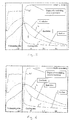
Figure 5 shows an example of cable temperatures and cross-linking without the present invention when line speed is 1,27 m/min, -
Figure 6 shows the example ofFig. 5 with the present invention when line speed is 1,72 m/min, -
Figure 7 shows the example ofFig. 5 without the present invention when line speed is 1,72 m/min, -
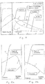
Figures 8a shows cable temperature and cross-linking without the present invention after vulcanization tube when line speed is 1,72 m/min, -
Figure 8b shows the situation 20 m later when compared toFig. 8a , -
Figure 9a shows cable temperature and cross-linking with the present invention just after the inductive heating device, and -
Figure 9b shows the situation 20 m later when compared toFig. 9a . -
Figure 1 shows a principle layout of a vulcanizing extrusion line. The vulcanizing extrusion line comprises a payoff 1, a metering capstan or metering caterpillar 2, apreheater 3 for a conductor element, an extrusion group with an extruder head 4, apostheater 5, avulcanization tube 6, acooling tube 7, a caterpillar or a capstan 8 and a take-up 9. - As discussed earlier operation and construction of the extrusion line described above is well-known to a person skilled in the art, and therefore operation or/and construction of the extrusion line is not described in detail here. Referring to said matter note here that for
example preheater 3 can be placed upstream of the metering capstan 2 etc. - In the cable manufacturing process described above, the insulation has to be extruded onto the conductor at a temperature sufficiently low as to avoid premature crosslinking in the extrusion equipment, as this would lead to defects of the insulation.
- After the extrusion step, the material has to be heated up at a temperature that is sufficiently high to start and complete the chemical reaction within the shortest possible time.
- The crosslinking reaction is carried out in the vulcanization tube, i.e. a tube surrounding the extruded electrical cable located downstream of the extrusion head, inside which the cable is heated up by radiant and/or convective heat transfer.
- The heat diffusion in the insulation material is however low, and the polymer layers close to the conductor will take the longest time to increase temperature and undergo the chemical reaction desired.
- As discussed above a well-known method to improve the heating/crosslinking process is to heat the conductor internally so that heat diffuses into the insulation material extruded also form inside and therefore accelerates the crosslinking reaction. This internal heating is materialized by using inductive heating procedure.
- As discussed earlier further said internal heating operates well in connection with low and medium voltage cables having relatively low insulation thicknesses, but the situation is completely different in connection with High Voltage and Extremely High Voltage cables having high insulation thicknesses. In High Voltage cables or in Extremely High Voltage cables the problems relate to eventual drooping of the insulation material as described earlier.
-
Figure 2 shows a principle layout of a vulcanizing line in which the present invention is used. InFigure 2 same reference numbers are used to indicate corresponding parts when compared toFigure 1 . -
Figure 2 shows in fact a part of a vulcanizing extrusion line, i.e. only the parts needed to understand the invention are shown. For example pay-off and take-up is not shown onFigure 2 . A person skilled in the art however instantly understands the structure and operation of the line shown inFigure 2 when looking for exampleFigure 2 together withfigure 1 . - The embodiment shown in
Figure 2 has an extrusion group with extruder head 4 and telescopic tube and, vulcanizingtube 6 andcooling tube 7 which in this embodiment is a device with closed-circuit gas cooling. Conductor element guided to the extruder head 4 is shown withreference number 12. - According to the essential idea of the invention there is also an
inductive heating device 10 placed after thevulcanization tube 6 for heating the coated conductor element, i.e. the point in the invention is that the coated conductor element is heated after thevulcanization tube 6 by using inductive heating. -
Figure 2 shows clearly that theinductive device 10 has been placed downstream of the vulcanization tube, i.e. after thevulcanization tube 6 and before coolingtube 7. - As described above in the invention, an inductive heating of the conductor is placed downstream of the
vulcanization tube 6. At this point of the process, the crosslinking reaction has progressed sufficiently so that the insulation is partially crosslinked close to the conductor and has increased stiffness or viscosity. Therefore it can be heated up from the conductor by means of inductive heating and thus accelerate completion of the crosslinking without drooping effects. - The facts described above permit to increase the line speed compared to the setup without said inductive heating. Said inductive heating, i.e. by using
inductive device 10 as a post heater in the way shown inFigure 2 completes the crosslinking process and also eliminates harmful drooping effects described earlier. -
Figures 3a, 3b and 4 describe said drooping effect.Figures 3a and 3b show schematically the difference of gravitational load towards and aside of two different conductors, namely 20 kV (Fig 3a ) and 150 kV cables (3b) having identical conductor diameters.Figures 3a and 3b show said matters in terms of shear stress in the insulation due to gravitational forces. Conductor element is shown withreference number 12. - The insulation material in areas B and below the
conductor element 12, due to its own weight, generates a shear stress in vertical direction along the separation line between areas A and B. The still hot plastic material will therefore have a tendency so sag, with loss of centering and roundness of the insulation. This tendency to sag depends on the level of shear stress on one hand, and on the melt strength on the other hand, which in turn decreases with increasing temperatures. - The matters discussed above and shown in
Figures 3a and 3b are shown with numbers inFigure 4 . The calculation ofFigure 4 as an example compares with numbers the situation of a 20 kV cable to a 150 kV cable of identical conductor element diameter (30,2 mm). It appears that the gravitational load in the 150 kV cable is almost 3 times bigger than in the 20 kV cable. Therefore, if the insulation material close to the conductor element of the 150 kV cable was heated up while still in thermoplastic state, it would sag to an unacceptable extent. -
Figures 5 - 9 show an example in which the situation is compared with the same product with and without the present invention. - Data of the example:
Copper Ac = 630 mm2, Uo = 150 kV - without inductive heating line speed is 1.27 m/min to reach cross-linking 96% (
Fig. 5 ) - without inductive heating with line speed 1.72 m/min cross-linking is 40% (
Fig. 7, Fig 8a and Fig 8b ) - with inductive heating line speed is 1.72 m/min to reach cross-linking 96% (
Fig. 6 ,Fig 9a and Fig.9b ) -
Figures 5, 6 and7 : - Curves: b = conductor temperature, g = insulation temperature, r = surface temperature, bl = cross-linking. The references b, g, r and bl are shown in the
Figures 5, 6 and7 . - X-axis from cross-head to end-seal
- Y-axis T = 0...300 °C / X = 0...100%
-
Figures 5 and 6 : - Curves: r = temperature, bl = cross-linking. The references r and bl are shown in
Figures 5 and 6 . - X-axis from conductor surface to cable surface
- Y-axis T = 0...300 °C / X = 0...100%
- The example shown above proves that by using the invention it is possible to obtain higher line speeds when compared to the technique of the prior art.
- The invention has been described above by using the embodiments described in the Figures. The embodiments shown are by no means intended to restrict the invention but the invention may be varied completely freely within the claims. The vulcanizing line used can be formed quite freely, i.e. the placements of various steps can vary and there can be additional steps, too. For example the coated conductor element can be also heated before the cooling step if needed, i.e. it is quite possible to provide the vulcanizing line with a pre-heater before the extrusion step. Said pre-heater can be for example an inductive heating device etc.
Claims (4)
- Method of crosslinking or vulcanizing an elongate element the method comprising the following steps:an extrusion step (4) in which a conductor element (12) is coated by a layer of crosslinkable material,a step in which a crosslinking reaction is carried out by processing the coated conductor element in a vulcanization tube (6) after the extrusion step, anda cooling step (7) in which the coated conductor element is cooled,characterized in that the method further comprises a step in which after the vulcanization tube (6) the coated conductor element is heated by using inductive heating (10), and that the step in which the coated conductor element is heated is carried out immediately before the cooling step.
- Method as claimed in claim 1, characterized in that the method further comprises a step in which the conductor element (12) is heated before the extrusion step.
- Arrangement for crosslinking or vulcanizing an elongate element in which arrangement a conductor element (12) is coated by a layer of crosslinkable material by using an extruder head (4), the crosslinking reaction is carried out after the extruder head in a vulcanization tube (6), and coated conductor element is cooled by using a cooling tube (7), characterized in that the arrangement further comprises an inductive heating device (10) placed after the vulcanization tube (6) for heating the coated conductor element, and that the inductive heating device (10) is placed immediately before the cooling tube (7).
- Arrangement as claimed in claim 3, characterized in that the arrangement further comprises a pre-heater for heating the conductor element before the extruder head (4).
Priority Applications (1)
| Application Number | Priority Date | Filing Date | Title |
|---|---|---|---|
| PL14150439T PL2755211T3 (en) | 2013-01-09 | 2014-01-08 | Method and arrangement of crosslinking or vulcanizing an elongate element |
Applications Claiming Priority (1)
| Application Number | Priority Date | Filing Date | Title |
|---|---|---|---|
| FI20135028 | 2013-01-09 |
Publications (2)
| Publication Number | Publication Date |
|---|---|
| EP2755211A1 EP2755211A1 (en) | 2014-07-16 |
| EP2755211B1 true EP2755211B1 (en) | 2019-03-06 |
Family
ID=49989491
Family Applications (1)
| Application Number | Title | Priority Date | Filing Date |
|---|---|---|---|
| EP14150439.9A Revoked EP2755211B1 (en) | 2013-01-09 | 2014-01-08 | Method and arrangement of crosslinking or vulcanizing an elongate element |
Country Status (5)
| Country | Link |
|---|---|
| EP (1) | EP2755211B1 (en) |
| CN (1) | CN103909638A (en) |
| PL (1) | PL2755211T3 (en) |
| RU (1) | RU2641654C2 (en) |
| TR (1) | TR201907963T4 (en) |
Families Citing this family (3)
| Publication number | Priority date | Publication date | Assignee | Title |
|---|---|---|---|---|
| TWI688972B (en) * | 2015-02-18 | 2020-03-21 | 瑞士商美莉佛公司 | Method and arrangement for cross-linking or vulcanizing an elongate element |
| CN105448433B (en) * | 2015-05-28 | 2017-07-21 | 安正(天津)新材料股份有限公司 | A kind of rear grafting device of silanes crosslinked cable production line |
| CN113871096B (en) * | 2021-10-11 | 2022-04-15 | 江苏宝安电缆有限公司 | Shutdown vulcanization process in production process of crosslinked polyethylene cable |
Citations (3)
| Publication number | Priority date | Publication date | Assignee | Title |
|---|---|---|---|---|
| DE2906173A1 (en) | 1979-02-17 | 1980-08-21 | Harald Sikora | Continuous vulcanisation of electrical conductors insulation - by inductive heating of enveloped conductor in pressurised gas chamber |
| US20040234640A1 (en) | 2003-03-17 | 2004-11-25 | Troester Gmbh & Co. Kg | Installation for producing cables |
| EP1562202A1 (en) | 2004-01-30 | 2005-08-10 | Troester GmbH & Co.KG | Method and apparatus for manufacture of cables with peroxide cross-linked insulative or semi-conductive layers |
Family Cites Families (4)
| Publication number | Priority date | Publication date | Assignee | Title |
|---|---|---|---|---|
| US3645656A (en) * | 1969-05-07 | 1972-02-29 | Anaconda Wire & Cable Co | Continuously manufactured cable |
| CH644548A5 (en) | 1982-02-01 | 1984-08-15 | Cossonay Cableries Trefileries | Method for crosslinking or vulcanising an elongate element, and device for implementing this method |
| FI20055014A0 (en) | 2005-01-10 | 2005-01-10 | Maillefer Sa | Device and method for heating electrical conduit |
| EP2015315B1 (en) * | 2007-07-12 | 2012-12-12 | Borealis Technology Oy | Process for preparing and crosslinking a cable comprising a polymer composition and a crosslinked cable |
-
2013
- 2013-12-26 RU RU2013158208A patent/RU2641654C2/en active
-
2014
- 2014-01-08 PL PL14150439T patent/PL2755211T3/en unknown
- 2014-01-08 EP EP14150439.9A patent/EP2755211B1/en not_active Revoked
- 2014-01-08 TR TR2019/07963T patent/TR201907963T4/en unknown
- 2014-01-09 CN CN201410009716.8A patent/CN103909638A/en active Pending
Patent Citations (6)
| Publication number | Priority date | Publication date | Assignee | Title |
|---|---|---|---|---|
| DE2906173A1 (en) | 1979-02-17 | 1980-08-21 | Harald Sikora | Continuous vulcanisation of electrical conductors insulation - by inductive heating of enveloped conductor in pressurised gas chamber |
| US20040234640A1 (en) | 2003-03-17 | 2004-11-25 | Troester Gmbh & Co. Kg | Installation for producing cables |
| EP1460648B1 (en) | 2003-03-17 | 2007-08-29 | Troester GmbH & Co.KG | Installation for cable production |
| EP1562202A1 (en) | 2004-01-30 | 2005-08-10 | Troester GmbH & Co.KG | Method and apparatus for manufacture of cables with peroxide cross-linked insulative or semi-conductive layers |
| DE102004004910A1 (en) | 2004-01-30 | 2005-08-25 | Troester Gmbh & Co. Kg | Processes and arrangements for manufacturing peroxide cross-linkable polyethylene cores for medium and high voltage cables |
| US20060182880A1 (en) | 2004-01-30 | 2006-08-17 | Troester Gmbh & Co. Kg | Method and equipment for producing cables with peroxide cross linked insulating and semiconducting layers |
Also Published As
| Publication number | Publication date |
|---|---|
| RU2013158208A (en) | 2015-07-10 |
| CN103909638A (en) | 2014-07-09 |
| RU2641654C2 (en) | 2018-01-19 |
| EP2755211A1 (en) | 2014-07-16 |
| PL2755211T3 (en) | 2019-09-30 |
| TR201907963T4 (en) | 2019-06-21 |
Similar Documents
| Publication | Publication Date | Title |
|---|---|---|
| EP2755211B1 (en) | Method and arrangement of crosslinking or vulcanizing an elongate element | |
| EP0007814B1 (en) | Manufacture of extruded products | |
| EP3059741B1 (en) | Method for cross-linking or vulcanizing an elongate element | |
| US4080131A (en) | Curing system for high voltage cross linked cables | |
| US3479419A (en) | Process and apparatus for curing material by induction heating | |
| US2732592A (en) | Extrusion of thermoplastic material | |
| CN102559046A (en) | Anti-sticking coating used for motor and electric appliance connection wire and its coating process | |
| US20040234640A1 (en) | Installation for producing cables | |
| US10020646B2 (en) | Busbar and method of manufacturing the same | |
| DE10104994B4 (en) | Method of making a cable | |
| JP7058268B2 (en) | Microcapillary wire coating die assembly | |
| EP2574439B1 (en) | Method and arrangement of crosslinking or vulcanising an elongate element | |
| JP6146338B2 (en) | Electric wire / cable manufacturing method | |
| DE2906173A1 (en) | Continuous vulcanisation of electrical conductors insulation - by inductive heating of enveloped conductor in pressurised gas chamber | |
| US9583237B2 (en) | Method of manufacturing a polymer-insulated conductor | |
| CN108091433B (en) | Processing method of high-voltage corrugated metal sleeve low-eccentricity polyethylene outer sheath power cable | |
| KR950004719B1 (en) | Apparatus for continuously producing heat-shrinkable crosslinked resin tube | |
| CN101335103A (en) | Electric cable with silicon rubber sheath and manufacturing method | |
| KR101425073B1 (en) | Continuous type cable manufacturing device and manufacturing method using the same | |
| KR20170055182A (en) | Apparatus for manufacturing dielectric of coaxial cable | |
| DE10202946A1 (en) | Medium or high voltage cable, produced by extruding an inner conducting layer onto a conductor, followed by an insulating layer and an outer conducting layer | |
| Rosato et al. | Wire and cable | |
| JPH0773761A (en) | Extruding type continuous molding bridge forming method for power cable and its device | |
| JP2017147240A (en) | Rubber material and wire/cable | |
| CN115579191A (en) | Conductor preheating method and system in cable crosslinking procedure |
Legal Events
| Date | Code | Title | Description |
|---|---|---|---|
| PUAI | Public reference made under article 153(3) epc to a published international application that has entered the european phase |
Free format text: ORIGINAL CODE: 0009012 |
|
| 17P | Request for examination filed |
Effective date: 20140108 |
|
| AK | Designated contracting states |
Kind code of ref document: A1 Designated state(s): AL AT BE BG CH CY CZ DE DK EE ES FI FR GB GR HR HU IE IS IT LI LT LU LV MC MK MT NL NO PL PT RO RS SE SI SK SM TR |
|
| AX | Request for extension of the european patent |
Extension state: BA ME |
|
| RIN1 | Information on inventor provided before grant (corrected) |
Inventor name: HUOTARI, PEKKA Inventor name: LEPPAENEN, JORMA |
|
| R17P | Request for examination filed (corrected) |
Effective date: 20150112 |
|
| RBV | Designated contracting states (corrected) |
Designated state(s): AL AT BE BG CH CY CZ DE DK EE ES FI FR GB GR HR HU IE IS IT LI LT LU LV MC MK MT NL NO PL PT RO RS SE SI SK SM TR |
|
| RIC1 | Information provided on ipc code assigned before grant |
Ipc: B29C 35/10 20060101ALI20180802BHEP Ipc: B29C 47/88 20060101ALI20180802BHEP Ipc: H01B 13/14 20060101AFI20180802BHEP |
|
| GRAP | Despatch of communication of intention to grant a patent |
Free format text: ORIGINAL CODE: EPIDOSNIGR1 |
|
| STAA | Information on the status of an ep patent application or granted ep patent |
Free format text: STATUS: GRANT OF PATENT IS INTENDED |
|
| INTG | Intention to grant announced |
Effective date: 20180912 |
|
| GRAS | Grant fee paid |
Free format text: ORIGINAL CODE: EPIDOSNIGR3 |
|
| GRAA | (expected) grant |
Free format text: ORIGINAL CODE: 0009210 |
|
| STAA | Information on the status of an ep patent application or granted ep patent |
Free format text: STATUS: THE PATENT HAS BEEN GRANTED |
|
| RIN1 | Information on inventor provided before grant (corrected) |
Inventor name: HUOTARI, PEKKA Inventor name: LEPPAENEN, JORMA |
|
| AK | Designated contracting states |
Kind code of ref document: B1 Designated state(s): AL AT BE BG CH CY CZ DE DK EE ES FI FR GB GR HR HU IE IS IT LI LT LU LV MC MK MT NL NO PL PT RO RS SE SI SK SM TR |
|
| REG | Reference to a national code |
Ref country code: GB Ref legal event code: FG4D |
|
| REG | Reference to a national code |
Ref country code: CH Ref legal event code: EP Ref country code: AT Ref legal event code: REF Ref document number: 1105651 Country of ref document: AT Kind code of ref document: T Effective date: 20190315 |
|
| REG | Reference to a national code |
Ref country code: DE Ref legal event code: R096 Ref document number: 602014042171 Country of ref document: DE |
|
| REG | Reference to a national code |
Ref country code: IE Ref legal event code: FG4D |
|
| REG | Reference to a national code |
Ref country code: DE Ref legal event code: R082 Ref document number: 602014042171 Country of ref document: DE Representative=s name: TBK, DE |
|
| REG | Reference to a national code |
Ref country code: NL Ref legal event code: MP Effective date: 20190306 |
|
| REG | Reference to a national code |
Ref country code: LT Ref legal event code: MG4D |
|
| PG25 | Lapsed in a contracting state [announced via postgrant information from national office to epo] |
Ref country code: LT Free format text: LAPSE BECAUSE OF FAILURE TO SUBMIT A TRANSLATION OF THE DESCRIPTION OR TO PAY THE FEE WITHIN THE PRESCRIBED TIME-LIMIT Effective date: 20190306 Ref country code: NO Free format text: LAPSE BECAUSE OF FAILURE TO SUBMIT A TRANSLATION OF THE DESCRIPTION OR TO PAY THE FEE WITHIN THE PRESCRIBED TIME-LIMIT Effective date: 20190606 Ref country code: SE Free format text: LAPSE BECAUSE OF FAILURE TO SUBMIT A TRANSLATION OF THE DESCRIPTION OR TO PAY THE FEE WITHIN THE PRESCRIBED TIME-LIMIT Effective date: 20190306 |
|
| PG25 | Lapsed in a contracting state [announced via postgrant information from national office to epo] |
Ref country code: BG Free format text: LAPSE BECAUSE OF FAILURE TO SUBMIT A TRANSLATION OF THE DESCRIPTION OR TO PAY THE FEE WITHIN THE PRESCRIBED TIME-LIMIT Effective date: 20190606 Ref country code: GR Free format text: LAPSE BECAUSE OF FAILURE TO SUBMIT A TRANSLATION OF THE DESCRIPTION OR TO PAY THE FEE WITHIN THE PRESCRIBED TIME-LIMIT Effective date: 20190607 Ref country code: LV Free format text: LAPSE BECAUSE OF FAILURE TO SUBMIT A TRANSLATION OF THE DESCRIPTION OR TO PAY THE FEE WITHIN THE PRESCRIBED TIME-LIMIT Effective date: 20190306 Ref country code: HR Free format text: LAPSE BECAUSE OF FAILURE TO SUBMIT A TRANSLATION OF THE DESCRIPTION OR TO PAY THE FEE WITHIN THE PRESCRIBED TIME-LIMIT Effective date: 20190306 Ref country code: RS Free format text: LAPSE BECAUSE OF FAILURE TO SUBMIT A TRANSLATION OF THE DESCRIPTION OR TO PAY THE FEE WITHIN THE PRESCRIBED TIME-LIMIT Effective date: 20190306 Ref country code: NL Free format text: LAPSE BECAUSE OF FAILURE TO SUBMIT A TRANSLATION OF THE DESCRIPTION OR TO PAY THE FEE WITHIN THE PRESCRIBED TIME-LIMIT Effective date: 20190306 |
|
| PG25 | Lapsed in a contracting state [announced via postgrant information from national office to epo] |
Ref country code: CZ Free format text: LAPSE BECAUSE OF FAILURE TO SUBMIT A TRANSLATION OF THE DESCRIPTION OR TO PAY THE FEE WITHIN THE PRESCRIBED TIME-LIMIT Effective date: 20190306 Ref country code: AL Free format text: LAPSE BECAUSE OF FAILURE TO SUBMIT A TRANSLATION OF THE DESCRIPTION OR TO PAY THE FEE WITHIN THE PRESCRIBED TIME-LIMIT Effective date: 20190306 Ref country code: PT Free format text: LAPSE BECAUSE OF FAILURE TO SUBMIT A TRANSLATION OF THE DESCRIPTION OR TO PAY THE FEE WITHIN THE PRESCRIBED TIME-LIMIT Effective date: 20190706 Ref country code: RO Free format text: LAPSE BECAUSE OF FAILURE TO SUBMIT A TRANSLATION OF THE DESCRIPTION OR TO PAY THE FEE WITHIN THE PRESCRIBED TIME-LIMIT Effective date: 20190306 Ref country code: ES Free format text: LAPSE BECAUSE OF FAILURE TO SUBMIT A TRANSLATION OF THE DESCRIPTION OR TO PAY THE FEE WITHIN THE PRESCRIBED TIME-LIMIT Effective date: 20190306 Ref country code: EE Free format text: LAPSE BECAUSE OF FAILURE TO SUBMIT A TRANSLATION OF THE DESCRIPTION OR TO PAY THE FEE WITHIN THE PRESCRIBED TIME-LIMIT Effective date: 20190306 Ref country code: SK Free format text: LAPSE BECAUSE OF FAILURE TO SUBMIT A TRANSLATION OF THE DESCRIPTION OR TO PAY THE FEE WITHIN THE PRESCRIBED TIME-LIMIT Effective date: 20190306 |
|
| PG25 | Lapsed in a contracting state [announced via postgrant information from national office to epo] |
Ref country code: SM Free format text: LAPSE BECAUSE OF FAILURE TO SUBMIT A TRANSLATION OF THE DESCRIPTION OR TO PAY THE FEE WITHIN THE PRESCRIBED TIME-LIMIT Effective date: 20190306 |
|
| REG | Reference to a national code |
Ref country code: DE Ref legal event code: R026 Ref document number: 602014042171 Country of ref document: DE |
|
| PLBI | Opposition filed |
Free format text: ORIGINAL CODE: 0009260 |
|
| PLAX | Notice of opposition and request to file observation + time limit sent |
Free format text: ORIGINAL CODE: EPIDOSNOBS2 |
|
| PG25 | Lapsed in a contracting state [announced via postgrant information from national office to epo] |
Ref country code: IS Free format text: LAPSE BECAUSE OF FAILURE TO SUBMIT A TRANSLATION OF THE DESCRIPTION OR TO PAY THE FEE WITHIN THE PRESCRIBED TIME-LIMIT Effective date: 20190706 |
|
| REG | Reference to a national code |
Ref country code: FI Ref legal event code: MDE Opponent name: TROESTER GMBH & CO. KG |
|
| 26 | Opposition filed |
Opponent name: TROESTER GMBH & CO. KG Effective date: 20191205 |
|
| PG25 | Lapsed in a contracting state [announced via postgrant information from national office to epo] |
Ref country code: DK Free format text: LAPSE BECAUSE OF FAILURE TO SUBMIT A TRANSLATION OF THE DESCRIPTION OR TO PAY THE FEE WITHIN THE PRESCRIBED TIME-LIMIT Effective date: 20190306 |
|
| PG25 | Lapsed in a contracting state [announced via postgrant information from national office to epo] |
Ref country code: SI Free format text: LAPSE BECAUSE OF FAILURE TO SUBMIT A TRANSLATION OF THE DESCRIPTION OR TO PAY THE FEE WITHIN THE PRESCRIBED TIME-LIMIT Effective date: 20190306 |
|
| PGFP | Annual fee paid to national office [announced via postgrant information from national office to epo] |
Ref country code: IT Payment date: 20200123 Year of fee payment: 7 Ref country code: DE Payment date: 20200129 Year of fee payment: 7 Ref country code: AT Payment date: 20191219 Year of fee payment: 7 Ref country code: PL Payment date: 20200103 Year of fee payment: 7 Ref country code: FI Payment date: 20200130 Year of fee payment: 7 |
|
| PGFP | Annual fee paid to national office [announced via postgrant information from national office to epo] |
Ref country code: FR Payment date: 20200127 Year of fee payment: 7 Ref country code: TR Payment date: 20200107 Year of fee payment: 7 |
|
| PG25 | Lapsed in a contracting state [announced via postgrant information from national office to epo] |
Ref country code: MC Free format text: LAPSE BECAUSE OF FAILURE TO SUBMIT A TRANSLATION OF THE DESCRIPTION OR TO PAY THE FEE WITHIN THE PRESCRIBED TIME-LIMIT Effective date: 20190306 |
|
| REG | Reference to a national code |
Ref country code: CH Ref legal event code: PL |
|
| GBPC | Gb: european patent ceased through non-payment of renewal fee |
Effective date: 20200108 |
|
| REG | Reference to a national code |
Ref country code: BE Ref legal event code: MM Effective date: 20200131 |
|
| PG25 | Lapsed in a contracting state [announced via postgrant information from national office to epo] |
Ref country code: LU Free format text: LAPSE BECAUSE OF NON-PAYMENT OF DUE FEES Effective date: 20200108 Ref country code: GB Free format text: LAPSE BECAUSE OF NON-PAYMENT OF DUE FEES Effective date: 20200108 |
|
| PG25 | Lapsed in a contracting state [announced via postgrant information from national office to epo] |
Ref country code: LI Free format text: LAPSE BECAUSE OF NON-PAYMENT OF DUE FEES Effective date: 20200131 Ref country code: BE Free format text: LAPSE BECAUSE OF NON-PAYMENT OF DUE FEES Effective date: 20200131 Ref country code: CH Free format text: LAPSE BECAUSE OF NON-PAYMENT OF DUE FEES Effective date: 20200131 |
|
| RDAF | Communication despatched that patent is revoked |
Free format text: ORIGINAL CODE: EPIDOSNREV1 |
|
| REG | Reference to a national code |
Ref country code: AT Ref legal event code: UEP Ref document number: 1105651 Country of ref document: AT Kind code of ref document: T Effective date: 20190306 |
|
| REG | Reference to a national code |
Ref country code: DE Ref legal event code: R064 Ref document number: 602014042171 Country of ref document: DE Ref country code: DE Ref legal event code: R103 Ref document number: 602014042171 Country of ref document: DE |
|
| PG25 | Lapsed in a contracting state [announced via postgrant information from national office to epo] |
Ref country code: IE Free format text: LAPSE BECAUSE OF NON-PAYMENT OF DUE FEES Effective date: 20200108 |
|
| RDAG | Patent revoked |
Free format text: ORIGINAL CODE: 0009271 |
|
| STAA | Information on the status of an ep patent application or granted ep patent |
Free format text: STATUS: PATENT REVOKED |
|
| REG | Reference to a national code |
Ref country code: FI Ref legal event code: MGE |
|
| 27W | Patent revoked |
Effective date: 20201225 |
|
| REG | Reference to a national code |
Ref country code: AT Ref legal event code: MA03 Ref document number: 1105651 Country of ref document: AT Kind code of ref document: T Effective date: 20201225 |
|
| PG25 | Lapsed in a contracting state [announced via postgrant information from national office to epo] |
Ref country code: MK Free format text: LAPSE BECAUSE OF FAILURE TO SUBMIT A TRANSLATION OF THE DESCRIPTION OR TO PAY THE FEE WITHIN THE PRESCRIBED TIME-LIMIT Effective date: 20190306 |