EP1839319B1 - Arrangement and method for heating an electrical conductor - Google Patents
Arrangement and method for heating an electrical conductor Download PDFInfo
- Publication number
- EP1839319B1 EP1839319B1 EP05746861A EP05746861A EP1839319B1 EP 1839319 B1 EP1839319 B1 EP 1839319B1 EP 05746861 A EP05746861 A EP 05746861A EP 05746861 A EP05746861 A EP 05746861A EP 1839319 B1 EP1839319 B1 EP 1839319B1
- Authority
- EP
- European Patent Office
- Prior art keywords
- induction means
- arrangement according
- splice box
- extrusion head
- heating
- Prior art date
- Legal status (The legal status is an assumption and is not a legal conclusion. Google has not performed a legal analysis and makes no representation as to the accuracy of the status listed.)
- Expired - Lifetime
Links
Images


Classifications
-
- H—ELECTRICITY
- H05—ELECTRIC TECHNIQUES NOT OTHERWISE PROVIDED FOR
- H05B—ELECTRIC HEATING; ELECTRIC LIGHT SOURCES NOT OTHERWISE PROVIDED FOR; CIRCUIT ARRANGEMENTS FOR ELECTRIC LIGHT SOURCES, IN GENERAL
- H05B6/00—Heating by electric, magnetic or electromagnetic fields
- H05B6/02—Induction heating
-
- H—ELECTRICITY
- H01—ELECTRIC ELEMENTS
- H01B—CABLES; CONDUCTORS; INSULATORS; SELECTION OF MATERIALS FOR THEIR CONDUCTIVE, INSULATING OR DIELECTRIC PROPERTIES
- H01B13/00—Apparatus or processes specially adapted for manufacturing conductors or cables
- H01B13/06—Insulating conductors or cables
- H01B13/14—Insulating conductors or cables by extrusion
- H01B13/143—Insulating conductors or cables by extrusion with a special opening of the extrusion head
-
- B—PERFORMING OPERATIONS; TRANSPORTING
- B29—WORKING OF PLASTICS; WORKING OF SUBSTANCES IN A PLASTIC STATE IN GENERAL
- B29C—SHAPING OR JOINING OF PLASTICS; SHAPING OF MATERIAL IN A PLASTIC STATE, NOT OTHERWISE PROVIDED FOR; AFTER-TREATMENT OF THE SHAPED PRODUCTS, e.g. REPAIRING
- B29C35/00—Heating, cooling or curing, e.g. crosslinking or vulcanising; Apparatus therefor
- B29C35/02—Heating or curing, e.g. crosslinking or vulcanizing during moulding, e.g. in a mould
- B29C35/08—Heating or curing, e.g. crosslinking or vulcanizing during moulding, e.g. in a mould by wave energy or particle radiation
- B29C35/10—Heating or curing, e.g. crosslinking or vulcanizing during moulding, e.g. in a mould by wave energy or particle radiation for articles of indefinite length
-
- H—ELECTRICITY
- H05—ELECTRIC TECHNIQUES NOT OTHERWISE PROVIDED FOR
- H05B—ELECTRIC HEATING; ELECTRIC LIGHT SOURCES NOT OTHERWISE PROVIDED FOR; CIRCUIT ARRANGEMENTS FOR ELECTRIC LIGHT SOURCES, IN GENERAL
- H05B6/00—Heating by electric, magnetic or electromagnetic fields
- H05B6/02—Induction heating
- H05B6/36—Coil arrangements
-
- B—PERFORMING OPERATIONS; TRANSPORTING
- B29—WORKING OF PLASTICS; WORKING OF SUBSTANCES IN A PLASTIC STATE IN GENERAL
- B29C—SHAPING OR JOINING OF PLASTICS; SHAPING OF MATERIAL IN A PLASTIC STATE, NOT OTHERWISE PROVIDED FOR; AFTER-TREATMENT OF THE SHAPED PRODUCTS, e.g. REPAIRING
- B29C35/00—Heating, cooling or curing, e.g. crosslinking or vulcanising; Apparatus therefor
- B29C35/02—Heating or curing, e.g. crosslinking or vulcanizing during moulding, e.g. in a mould
- B29C35/08—Heating or curing, e.g. crosslinking or vulcanizing during moulding, e.g. in a mould by wave energy or particle radiation
- B29C35/0805—Heating or curing, e.g. crosslinking or vulcanizing during moulding, e.g. in a mould by wave energy or particle radiation using electromagnetic radiation
- B29C2035/0811—Heating or curing, e.g. crosslinking or vulcanizing during moulding, e.g. in a mould by wave energy or particle radiation using electromagnetic radiation using induction
Definitions
- the present invention relates to an arrangement according to the preamble of claim 1 and particularly to an arrangement for inductively heating an electrical conductor after the extrusion head in a process of manufacturing electrical cables having a cross-linkable insulation layer surrounding the electrical conductor. Additionally, the present invention relates to a method according to the preamble of claim 18 and particularly to a method for inductively heating an electrical conductor after the extrusion head in a process of manufacturing electrical cables having insulation layers surrounding the electrical conductor.
- the production speed is significantly dependent on how efficiently the Insulation layer(s) of the extruded cable can be heated to the temperature necessary for the crosslinking reaction.
- the main limiting factor of the heating is the low heat conduction rate inside the insulation. Therefore different arrangements have been used to speed up the heating rate of the insulation layer. These arrangements comprise pneheaters for heating the electrical conductor to a temperature above the ambient temperature prior to entering the extrusion head of the production line for heating the insulation layer also from the inside.
- this preheating is limited because of, for instance, copper oxidation, conductor tape deformation and moisture-block material degradation.
- radiant heat sources have been used, but the maximum admissible temperature of the outer surface of the extruded cable limits the utilisation of these radiant heat sources.
- Inductive post-heaters are used for this heating purpose after the extrusion of the insulation layer of the cable.
- inductive post-heating comprise inductively heating the extrusion tip and the die in order to promote crosslinking of the extruded insulation layer. Also is known to inductively heat the electrical conductor of a cable by a compact inductive heater located downstream of the extrusion head.
- the arrangement of the present invention also protects splice-box and other external parts of the splice box from heating.
- Other external parts may be any parts outside the splice-box.
- the invention is based on the idea of providing an arrangement and a method for inductively heating the electrical conductor of an electrical cable after the extrusion step such as to provide a modular approach for the inductive heating of the electrical conductor of an electrical cable.
- This simple construction for the inductive post-heater comprises induction means, preferably a coil, mounted downstream of the extrusion head for generating a magnetic field and guide means, preferably ferrite cores, located in the splice box to prevent inductive heating of the splice-box itself. Therefore the solution of the present invention comprises distinctive induction means mounted around the electrical cable and distinctive guide means mounted in a splice box around the induction means. This arrangement allows for easy changing of the coil during production stops when the splice-box is open.
- An advantage of the arrangement and method of the invention is the modular approach for the post-heating of the electrical conductor after the extrusion of the insulating layer, which provides a simple construction with improved ergonomy for the heater and easier maintenance of the heater, as well as an efficient method for post-heating the electrical conductor.
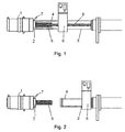
- Figure 1 is a schematic view of one embodiment of the present invention when the splice box is closed as during production.
- an extrusion head 1 of a production line for an electrical cable 8 comprising an electrical conductor and one to three layers including an insulation layer surrounding the electrical conductor.
- layers are extruded on an electrical conductor, which may be copper, aluminum or any other metal suitable for the purpose. After this extrusion, the layers have to be crosslinked in order to provide the desired properties for said insulation layer.
- the layers have to be heated to a predetermined temperature. In the present invention, the heating of the layers is at least partly accomplished by inductively heating the electrical conductor.
- the arrangement of the present invention comprises coil 5 as induction means for generating a magnetic field.
- the coil 5 is mounted on the extrusion head 1 of the production line downstream of the extrusion head 1.
- the mounting of the coil 5 to the extrusion head 1 is performed with a support, which in this embodiment is a flange 2, such that the coil 5 is mounted on the flange 2 and the flange 2 is connected to the extrusion head 1.
- the support may also be any other suitable construction for supporting the coil 5.
- the flange 2 is further provided with electrical connections 7 for operating the induction means, in this case the coil 5.
- the coil 5 may be possibly connected directly to the extrusion head, in which case also the electrical connections 7 may be connected directly to the coil 5.
- the coil 5 is arranged such that it surrounds the electrical cable 8 as the cable 8 comes from the extrusion head 1. Therefore the magnetic field generated by the coil 5 induces a dissipative current to the electrical conductor of the electrical cable 8 for heating the electrical conductor. Heated electrical conductor in turn heats the insulation layer to a temperature necessary for the crosslinking reaction.
- the induction means, the coil 5, form the first distinctive part of the arrangement for heating the electrical conductor.
- the first distinctive part may, as described above, also comprise a support, the flange 2, for supporting the induction means and for mounting the induction means to the extrusion head 1, and electrical connections 7 for operating the induction means.
- the present arrangement for heating the electrical conductor comprises also a second distinctive part.
- This second distinctive part comprises guide means provided in a splice box 3 for directing the magnetic field created with the induction means in order to prevent heating of the splice-box 3 itself.
- the guide means are ferrite cores 4 arranged in the splice box 3 around the induction means, but any other suitable guide means may be employed to accomplish the same purpose.
- the ferrite cores 4 or other guide means may be positioned in various ways to provide the function of directing magnetic field towards the electrical conductor.
- the ferrite cores 4 are mounted in splice box 3 of the production line.
- the splice box 3 is arranged over the coil 5 such that it surrounds the coil 5.
- the splice box 3 is removably connected to the flange 2, but when there is no flange 2 or any other support for the coil 5 the slice box 3 may be possible to connect directly to the extrusion head 1.
- the ferrite cores 4 are preferable integrated to the internal surfaces of the splice box 3.
- Various techniques and means may be used to mount or integrate the ferrite cores 4 to the splice box 3.
- the purpose for using the ferrite cores 3 is to avoid inductive heating of the other parts of the production line, such as the splice box 3 or steel tube enclosing the electrical cable 8.
- the complete inductive heating arrangement is formed from the two above mentioned distinctive parts arranged downstream of the extrusion head and it is operable when the splice box 3 is connected to the extrusion head 1.
- the first distinctive part is connected to the extrusion head 1 and comprises a support flange 2 with an inductive coil 5 as induction means surrounding the electrical cable 8 and electrical connections 7 for operating the induction means 5, and the second distinctive part comprises ferrite cores 4 as guide means provided in a splice box 3 and surrounding the inductive coil 5 for directing the magnetic field created with the coil 5.
- the coil 5 mounted to the flange 2 extends inside the splice box 3 in the direction of the electrical cable 8 surrounding the cable 8, and the ferrite cores 4 provided in the splice box 3 surround the coil 5.
- the two distinctive parts of the inductive heating arrangement are provided inside a splice box 3, which enables to change the induction means, the coil, easily since the splice box may be opened. Therefore there is no longer need to remove additional equipments, such as X-ray devices, from the production line for disassembly of the extrusion head and/or the post-heater.
- FIG 2 shows the embodiment of the Figure 1 when the splice box 3 is opened for changing the coil after the production line is shut-down.
- an X-ray device 6 is provided in the splice box 3 between the respective ends of the splice box 3, as shown in Figure 2 .
- the splice box 3 is opened it is moved way from the extrusion head 1 so that the coil 5 is exposed. Then the coil 5 may be changed or the extrusion head 1 may be dissembled for maintenance without removing the X-ray device 6. This way also a conductor joint may be done without removing the X-ray device 6 or the coil 5.
- Mentioned X-ray measuring device 6 may be provided as part of the splice box 3 or as an extension of the splice box 3, as is shown in Figure 1 . Also any other additional device may be provided instead of the X-ray measuring device 6 as part of the splice box 3 or as an extension of the splice box 3.
- Figures 3, 4 and 5 show another embodiment of the present invention.
- the X-ray device 6 is arranged directly after the extrusion head 1 and the coil 5 is provided after the X-ray device 6, as shown in Figure 3 .
- Guiding means, ferrite cores 5, are provided in the splice box 3, as in the embodiment of Figures 1 and 2 .
- X-ray device 6 is removably connected to the downstream side of the extrusion head 1 and the coil 5 is connected to the X-ray device 6 using flange 2 or some other suitable means.
- Flange 2 is provided with electrical connections 7.
- Coil 5 surrounds the cable 8 for heating the conductor and the splice box 3 is arranged around the coil 5, when the splice box 3 is closed. With this arrangement the X-ray device can measure cable 8 dimensions right after the extrusion head 1 and for instance vibrations do not affect the readings.
- This embodiment of Figure 3 comprises also support means 9 for supporting the X-ray device 6 together with the coil 5.
- the post-heater assembly is shown in operating state.
- These support means 9 are arranged such that X-ray device 6 and the coil 5 may be moved along the support means 9 downwards from the extrusion head 1.
- these support means 9 are guiding bars for guiding the X-ray device and the coil 5 when the splice box 3 is opened.
- These support means 9 may further comprise a stopper 10 for limiting the movement of the X-ray device 6 along the support means 9. This way the X-ray device 6 may be moved a predetermined distance, determined by the stopper, along the support means 9.
- Stopper 10 may be any means for limiting the moving of the X-ray device 6.
- Support means 9 may also be arranged without any stopper 10.
- Figure 4 shows the embodiment of Figure 3 during coil change and/or during extrusion head disassembly.
- the X-ray device 6 is moved downwards from the extrusion head 1 a distance determined by the stopper 10 and the splice box 3 is fully or at least partly opened.
- the X-ray device 6 is disconnected from the extrusion head 1 and the extrusion head 1 may be disassembled and simultaneously the coil 5 may be changed by disconnecting it from the X-ray device 6.
- Figure 5 shows the embodiment of Figure 3 during conductor joint and/or during extrusion head disassembly.
- the X-ray device 6 is disconnected from the extrusion head 1 and the splice box 3 is opened.
- the X-ray device 6 and the coil 5 may be moved along the support means 9 together with the splice box 3 when the splice box 3 is opened.
- the cable 8 may be accessed for making a joint 12 or the extrusion head 1 may be disassembled, as shown in Figure 5 .
- the modular approach of the arrangement of the present invention for heating electrical conductor downstream of an extrusion head is constructed so as that the induction means for generating a magnetic field and the guide means for guiding the magnetic field form two distinctive parts of the post-heater.
- the above construction allows the utilization of the splice box for heating the conductor downstream of the extrusion head. In that the case the coil and the ferrite cores do not form an integral part so that more freedom is created for maintenance and changes of the post-heater.
- the present invention relates also to a method for heating an electrical conductor downstream of an extrusion head 1 in production line of electrical cables.
- a single insulation layer or several layers together are extruded in an extrusion head on the electrical conductor to produce an electrical cable.
- the insulation layer needs to be heated to a predetermined temperature for crosslinking reaction to occur in the insulation layer.
- This heating is accomplished at least partly by creating a magnetic field by induction means mounted downstream of the extrusion head.
- the magnetic filed is created by a coil arranged around the electrical cable.
- the induction means are operated by electrical connections such that the induction means induce a dissipative current to the electrical conductor. This current heats the electrical conductor.
- the magnetic field created with the induction means is directed by guide means provided in a splice box in order to prevent heating of the splice-box itself.
- ferrite cores are used as guide means to direct the magnetic field and to avoid inductive heating of other parts of the production line. The method simplifies the post-heating of the electrical conductor of the electrical cable so as to provide more efficient crosslinking of the insulation layer and more efficient production of electrical cable.
- the properties of the produced cable 8 may be measuring with an X-ray device 6 provided downstream of the induction means 5 and arranged in the splice box 3. Alternatively the properties of the cable 8 may be measured with an X-ray device 6 provided upstream of the induction means 5 and connected to the extrusion head 1.
Landscapes
- Physics & Mathematics (AREA)
- Health & Medical Sciences (AREA)
- Electromagnetism (AREA)
- Engineering & Computer Science (AREA)
- Manufacturing & Machinery (AREA)
- Toxicology (AREA)
- Oral & Maxillofacial Surgery (AREA)
- Thermal Sciences (AREA)
- Extrusion Of Metal (AREA)
- General Induction Heating (AREA)
- Length-Measuring Devices Using Wave Or Particle Radiation (AREA)
Description
- The present invention relates to an arrangement according to the preamble of
claim 1 and particularly to an arrangement for inductively heating an electrical conductor after the extrusion head in a process of manufacturing electrical cables having a cross-linkable insulation layer surrounding the electrical conductor. Additionally, the present invention relates to a method according to the preamble of claim 18 and particularly to a method for inductively heating an electrical conductor after the extrusion head in a process of manufacturing electrical cables having insulation layers surrounding the electrical conductor. - Different means are known to enhance the production speed of electrical cables. The production speed is significantly dependent on how efficiently the Insulation layer(s) of the extruded cable can be heated to the temperature necessary for the crosslinking reaction. The main limiting factor of the heating is the low heat conduction rate inside the insulation. Therefore different arrangements have been used to speed up the heating rate of the insulation layer. These arrangements comprise pneheaters for heating the electrical conductor to a temperature above the ambient temperature prior to entering the extrusion head of the production line for heating the insulation layer also from the inside. However, this preheating is limited because of, for instance, copper oxidation, conductor tape deformation and moisture-block material degradation. Also radiant heat sources have been used, but the maximum admissible temperature of the outer surface of the extruded cable limits the utilisation of these radiant heat sources. Furthermore, Inductive post-heaters are used for this heating purpose after the extrusion of the insulation layer of the cable.
- Known arrangements for using inductive post-heating comprise inductively heating the extrusion tip and the die in order to promote crosslinking of the extruded insulation layer. Also is known to inductively heat the electrical conductor of a cable by a compact inductive heater located downstream of the extrusion head.
- As examples of the prior art
US-A-2004/0 234 640 andJP-A-04 014 793 - In these prior art arrangements the post-heating is provided by an add-on equipment in the extrusion line of an insulation layer of a cable. Therefore these known equipment are separate compact devices that may be added to a extrusion line.
- One of the disadvantages associated with the prior art inductive heating arrangements is that at production changes, additional equipment, such as X-ray measuring device, has to be removed to gain access to the inductive heating device for maintenance, dimensional change purposes or other process needs related to the inductive heating device.
- Another disadvantage associated with the prior art is having both the coil and the protective field guiding elements (typically ferrites) in the same construction. This makes individual coils heavy, expensive and difficult to clean and maintain.
- It is thus an object of the present invention to provide an arrangement and method for overcoming the above disadvantages. The objects of the invention are achieved by an arrangement according to
claim 1. - Additionally, objects of the invention are achieved by a method according to claim 18.
- Thus the arrangement of the present invention also protects splice-box and other external parts of the splice box from heating. Other external parts may be any parts outside the splice-box.
- The preferred embodiments of the invention are disclosed In the dependent claims.
- The invention is based on the idea of providing an arrangement and a method for inductively heating the electrical conductor of an electrical cable after the extrusion step such as to provide a modular approach for the inductive heating of the electrical conductor of an electrical cable. This simple construction for the inductive post-heater comprises induction means, preferably a coil, mounted downstream of the extrusion head for generating a magnetic field and guide means, preferably ferrite cores, located in the splice box to prevent inductive heating of the splice-box itself. Therefore the solution of the present invention comprises distinctive induction means mounted around the electrical cable and distinctive guide means mounted in a splice box around the induction means. This arrangement allows for easy changing of the coil during production stops when the splice-box is open.
- An advantage of the arrangement and method of the invention is the modular approach for the post-heating of the electrical conductor after the extrusion of the insulating layer, which provides a simple construction with improved ergonomy for the heater and easier maintenance of the heater, as well as an efficient method for post-heating the electrical conductor.
- In the following the invention will be described in greater detail by means of preferred embodiments with reference to the accompanying drawings, in which
-
Figure 1 shows schematically one embodiment of the present invention in operating state. -
Figure 2 shows the embodiment ofFigure 1 when the splice box is opened. -
Figure 3 shows schematically another embodiment of the invention in operating state. -
Figure 4 shows the embodiment ofFigure 3 when the splice box is opened. -
Figure 5 shows the embodiment ofFigure 3 during conductor joint. -
Figure 1 is a schematic view of one embodiment of the present invention when the splice box is closed as during production. InFigure 1 it is shown anextrusion head 1 of a production line for anelectrical cable 8 comprising an electrical conductor and one to three layers including an insulation layer surrounding the electrical conductor. In production of electrical cables, layers are extruded on an electrical conductor, which may be copper, aluminum or any other metal suitable for the purpose. After this extrusion, the layers have to be crosslinked in order to provide the desired properties for said insulation layer. For the crosslinking reaction the layers have to be heated to a predetermined temperature. In the present invention, the heating of the layers is at least partly accomplished by inductively heating the electrical conductor. - As shown in
Figure 1 , the arrangement of the present invention comprisescoil 5 as induction means for generating a magnetic field. Thecoil 5 is mounted on theextrusion head 1 of the production line downstream of theextrusion head 1. The mounting of thecoil 5 to theextrusion head 1 is performed with a support, which in this embodiment is aflange 2, such that thecoil 5 is mounted on theflange 2 and theflange 2 is connected to theextrusion head 1. The support may also be any other suitable construction for supporting thecoil 5. Theflange 2 is further provided withelectrical connections 7 for operating the induction means, in this case thecoil 5. Instead of acoil 5 also other induction means may be employed for heating the electrical conductor of theelectrical cable 8. Also the coil may be possibly connected directly to the extrusion head, in which case also theelectrical connections 7 may be connected directly to thecoil 5. - The
coil 5 is arranged such that it surrounds theelectrical cable 8 as thecable 8 comes from theextrusion head 1. Therefore the magnetic field generated by thecoil 5 induces a dissipative current to the electrical conductor of theelectrical cable 8 for heating the electrical conductor. Heated electrical conductor in turn heats the insulation layer to a temperature necessary for the crosslinking reaction. - The induction means, the
coil 5, form the first distinctive part of the arrangement for heating the electrical conductor. The first distinctive part may, as described above, also comprise a support, theflange 2, for supporting the induction means and for mounting the induction means to theextrusion head 1, andelectrical connections 7 for operating the induction means. - The present arrangement for heating the electrical conductor comprises also a second distinctive part. This second distinctive part comprises guide means provided in a
splice box 3 for directing the magnetic field created with the induction means in order to prevent heating of the splice-box 3 itself. In this particular embodiment shown inFigure 1 , the guide means areferrite cores 4 arranged in thesplice box 3 around the induction means, but any other suitable guide means may be employed to accomplish the same purpose. Theferrite cores 4 or other guide means may be positioned in various ways to provide the function of directing magnetic field towards the electrical conductor. - In the present invention the
ferrite cores 4 are mounted insplice box 3 of the production line. Thesplice box 3 is arranged over thecoil 5 such that it surrounds thecoil 5. As shown inFigure 1 , in this embodiment of the invention thesplice box 3 is removably connected to theflange 2, but when there is noflange 2 or any other support for thecoil 5 theslice box 3 may be possible to connect directly to theextrusion head 1. Theferrite cores 4 are preferable integrated to the internal surfaces of thesplice box 3. Various techniques and means may be used to mount or integrate theferrite cores 4 to thesplice box 3. The purpose for using theferrite cores 3 is to avoid inductive heating of the other parts of the production line, such as thesplice box 3 or steel tube enclosing theelectrical cable 8. - The complete inductive heating arrangement is formed from the two above mentioned distinctive parts arranged downstream of the extrusion head and it is operable when the
splice box 3 is connected to theextrusion head 1. In the case ofFigure 1 the first distinctive part is connected to theextrusion head 1 and comprises asupport flange 2 with aninductive coil 5 as induction means surrounding theelectrical cable 8 andelectrical connections 7 for operating the induction means 5, and the second distinctive part comprisesferrite cores 4 as guide means provided in asplice box 3 and surrounding theinductive coil 5 for directing the magnetic field created with thecoil 5. In this case thecoil 5 mounted to theflange 2 extends inside thesplice box 3 in the direction of theelectrical cable 8 surrounding thecable 8, and theferrite cores 4 provided in thesplice box 3 surround thecoil 5. - In the invention the two distinctive parts of the inductive heating arrangement are provided inside a
splice box 3, which enables to change the induction means, the coil, easily since the splice box may be opened. Therefore there is no longer need to remove additional equipments, such as X-ray devices, from the production line for disassembly of the extrusion head and/or the post-heater. -
Figure 2 shows the embodiment of theFigure 1 when thesplice box 3 is opened for changing the coil after the production line is shut-down. In that case anX-ray device 6 is provided in thesplice box 3 between the respective ends of thesplice box 3, as shown inFigure 2 . When thesplice box 3 is opened it is moved way from theextrusion head 1 so that thecoil 5 is exposed. Then thecoil 5 may be changed or theextrusion head 1 may be dissembled for maintenance without removing theX-ray device 6. This way also a conductor joint may be done without removing theX-ray device 6 or thecoil 5. - Mentioned
X-ray measuring device 6 may be provided as part of thesplice box 3 or as an extension of thesplice box 3, as is shown inFigure 1 . Also any other additional device may be provided instead of theX-ray measuring device 6 as part of thesplice box 3 or as an extension of thesplice box 3. -
Figures 3, 4 and5 show another embodiment of the present invention. In this embodiment theX-ray device 6 is arranged directly after theextrusion head 1 and thecoil 5 is provided after theX-ray device 6, as shown inFigure 3 . Guiding means,ferrite cores 5, are provided in thesplice box 3, as in the embodiment ofFigures 1 and 2 .X-ray device 6 is removably connected to the downstream side of theextrusion head 1 and thecoil 5 is connected to theX-ray device 6 usingflange 2 or some other suitable means.Flange 2 is provided withelectrical connections 7.Coil 5 surrounds thecable 8 for heating the conductor and thesplice box 3 is arranged around thecoil 5, when thesplice box 3 is closed. With this arrangement the X-ray device can measurecable 8 dimensions right after theextrusion head 1 and for instance vibrations do not affect the readings. - This embodiment of
Figure 3 comprises also support means 9 for supporting theX-ray device 6 together with thecoil 5. In thisFigure 3 the post-heater assembly is shown in operating state. These support means 9 are arranged such thatX-ray device 6 and thecoil 5 may be moved along the support means 9 downwards from theextrusion head 1. In a preferred embodiment these support means 9 are guiding bars for guiding the X-ray device and thecoil 5 when thesplice box 3 is opened. These support means 9 may further comprise astopper 10 for limiting the movement of theX-ray device 6 along the support means 9. This way theX-ray device 6 may be moved a predetermined distance, determined by the stopper, along the support means 9.Stopper 10 may be any means for limiting the moving of theX-ray device 6. Support means 9 may also be arranged without anystopper 10. -
Figure 4 shows the embodiment ofFigure 3 during coil change and/or during extrusion head disassembly. In this situation theX-ray device 6 is moved downwards from the extrusion head 1 a distance determined by thestopper 10 and thesplice box 3 is fully or at least partly opened. Thus, theX-ray device 6 is disconnected from theextrusion head 1 and theextrusion head 1 may be disassembled and simultaneously thecoil 5 may be changed by disconnecting it from theX-ray device 6. -
Figure 5 shows the embodiment ofFigure 3 during conductor joint and/or during extrusion head disassembly. In this situation theX-ray device 6 is disconnected from theextrusion head 1 and thesplice box 3 is opened. TheX-ray device 6 and thecoil 5 may be moved along the support means 9 together with thesplice box 3 when thesplice box 3 is opened. When thesplice box 3 is opened and theX-ray device 6 moved with thecoil 5 downwards from theextrusion head 1, thecable 8 may be accessed for making a joint 12 or theextrusion head 1 may be disassembled, as shown inFigure 5 . - The modular approach of the arrangement of the present invention for heating electrical conductor downstream of an extrusion head is constructed so as that the induction means for generating a magnetic field and the guide means for guiding the magnetic field form two distinctive parts of the post-heater. The above construction allows the utilization of the splice box for heating the conductor downstream of the extrusion head. In that the case the coil and the ferrite cores do not form an integral part so that more freedom is created for maintenance and changes of the post-heater.
- The present invention relates also to a method for heating an electrical conductor downstream of an
extrusion head 1 in production line of electrical cables. In the method, a single insulation layer or several layers together are extruded in an extrusion head on the electrical conductor to produce an electrical cable. After the extrusion step the insulation layer needs to be heated to a predetermined temperature for crosslinking reaction to occur in the insulation layer. This heating is accomplished at least partly by creating a magnetic field by induction means mounted downstream of the extrusion head. In a preferred embodiment the magnetic filed is created by a coil arranged around the electrical cable. The induction means are operated by electrical connections such that the induction means induce a dissipative current to the electrical conductor. This current heats the electrical conductor. - Furthermore, the magnetic field created with the induction means is directed by guide means provided in a splice box in order to prevent heating of the splice-box itself. In the preferred embodiment, ferrite cores are used as guide means to direct the magnetic field and to avoid inductive heating of other parts of the production line. The method simplifies the post-heating of the electrical conductor of the electrical cable so as to provide more efficient crosslinking of the insulation layer and more efficient production of electrical cable.
- The properties of the produced
cable 8 may be measuring with anX-ray device 6 provided downstream of the induction means 5 and arranged in thesplice box 3. Alternatively the properties of thecable 8 may be measured with anX-ray device 6 provided upstream of the induction means 5 and connected to theextrusion head 1.
Claims (23)
- An arrangement for inductively heating an electrical conductor after the extrusion head in a process of manufacturing electrical cables (8) having insulation layer on the electrical conductor, the arrangement comprising a splice box, induction means (5) for generating a magnetic field and heating the conductor and guide means for directing the magnetic field created with the induction means, characterized in that the induction means (5) form a first distinctive part and the guide means (4) are provided to the splice box to form a second distinctive part such that when the splice box (3) is closed the guide means (4) surround the induction means (5) and when the splice box (3) is opened the induction means (5) are exposed.
- An arrangement according to claim 1, characterized in that induction means (5) is a coil arranged around the electrical cable (8).
- An arrangement according to claim 1 or 2, characterized in that first distinctive part further comprises a support (2) for supporting the induction means (5).
- An arrangement according to any preceding claim 1 - 3, characterized in that first distinctive part further comprises electrical connections (7) for operating the induction means (5).
- An arrangement according to any preceding claim 1 - 4, characterized in that guide means (4) are ferrite cores provided in the splice box (3) and surrounding the induction means (5) for guiding magnetic field created by the induction means (5) to protect the splice-box from heating.
- An arrangement according to any preceding claim 1 - 5, characterized in that support (2) is a flange connected to the extrusion head (1).
- An arrangement according to any preceding claim 1, characterized in that first distinctive part is connected to the extrusion head (1) and comprises a support flange (2) with an inductive coil as induction means (5) surrounding the electrical cable (8) and electrical connections (7) for operating the induction means (5), and that second distinctive part comprises ferrite cores as guide means (4) surrounding the inductive coil and provided in a splice box for directing the magnetic field created with the induction means (5) to protect the splice-box from heating.
- An arrangement according to any preceding claim 1 - 7, characterized in that a X-ray measuring device (6) is part of the splice box (3).
- An arrangement according to claim 8, characterized in that that the X-ray measuring device (6) is arranged downstream of the induction means (5).
- An arrangement according to claims 8 or 9, characterized in that the X-ray measuring device (6) is arranged between the respective ends of the splice box (3).
- An arrangement according to any preceding claim 1 - 5, characterized in that the X-ray measuring device (6) is arranged upstream of the induction means (5).
- An arrangement according to claim 11, characterized in that the X-ray measuring device (6) is revomably connected to the extrusion head (1).
- An arrangement according to claims 11 or 12, characterized in that the support (2) is a flange connected to the downstream side of the X-ray device (6).
- An arrangement according to any preceding claim 10 - 13, characterized in that the arrangement further comprises support means (9) for moving away from the extrusion head (1) and supporting the X-ray device (6) and the induction means (5) when splice box (3) is opened.
- An arrangement according to claim 14, characterized in that the support means (9) comprises a stopper (10) for limiting the movement of the X-ray device (6) and induction means (5) when splice box (3) is opened.
- An arrangement according to claim 14 or 15, characterized in that the support means (9) are guiding bars.
- An arrangement according to any preceding claim 4 - 16, characterized in that connections (7) are provided in the support (2).
- Method for inductively heating an electrical conductor after the extrusion head (1) in a process of manufacturing electrical cables (8) having insulation layer surrounding the electrical conductor, the method comprising steps of:- extruding an insulation layer through an extrusion head on an electrical conductor in order to produce an electrical cable (8); and- creating a magnetic field by induction means (5), characterized in that the method further comprises a step of:- directing the magnetic field created with the induction means by guide means (4) provided in a splice box (3) in order to protect external parts from heating such that when the splice box (3) is closed the guide means surround the induction means (5).
- A method according to claim 18, characterized by creating the magnetic filed by a coil arranged around the electrical cable (8).
- A method according to claim 18 or 19, characterized by operating the induction means by electrical connections.
- A method according to any preceding claim 18 - 20, characterized by using ferrite cores provided in the splice box and surrounding the induction means for guiding the magnetic field created by the induction means (5) to protect external parts from heating.
- A method according to any preceding claim 18 - 20, characterized by measuring the properties of the cable (8) with a X-ray device (6) provided downstream of the induction means (5) and arranged in the splice box (3).
- A method according to any preceding claim 18 - 20, characterized by measuring the properties of the cable (8) with a X-ray device (6) provided upstream of the induction means (5) and connected to the extrusion head (1).
Priority Applications (1)
| Application Number | Priority Date | Filing Date | Title |
|---|---|---|---|
| PL05746861T PL1839319T3 (en) | 2005-01-10 | 2005-06-02 | Arrangement and method for heating an electrical conductor |
Applications Claiming Priority (2)
| Application Number | Priority Date | Filing Date | Title |
|---|---|---|---|
| FI20055014A FI20055014A0 (en) | 2005-01-10 | 2005-01-10 | Device and method for heating electrical conduit |
| PCT/FI2005/050190 WO2006072650A1 (en) | 2005-01-10 | 2005-06-02 | Arrangement and method for heating an electrical conductor |
Publications (2)
| Publication Number | Publication Date |
|---|---|
| EP1839319A1 EP1839319A1 (en) | 2007-10-03 |
| EP1839319B1 true EP1839319B1 (en) | 2012-10-17 |
Family
ID=34112665
Family Applications (1)
| Application Number | Title | Priority Date | Filing Date |
|---|---|---|---|
| EP05746861A Expired - Lifetime EP1839319B1 (en) | 2005-01-10 | 2005-06-02 | Arrangement and method for heating an electrical conductor |
Country Status (9)
| Country | Link |
|---|---|
| EP (1) | EP1839319B1 (en) |
| JP (1) | JP4758440B2 (en) |
| KR (1) | KR101154619B1 (en) |
| CN (1) | CN101124645B (en) |
| ES (1) | ES2397344T3 (en) |
| FI (1) | FI20055014A0 (en) |
| PL (1) | PL1839319T3 (en) |
| RU (1) | RU2372680C2 (en) |
| WO (1) | WO2006072650A1 (en) |
Cited By (1)
| Publication number | Priority date | Publication date | Assignee | Title |
|---|---|---|---|---|
| EP2755211A1 (en) | 2013-01-09 | 2014-07-16 | Maillefer S.A. | Method and arrangement of crosslinking or vulcanizing an elongate element |
Families Citing this family (4)
| Publication number | Priority date | Publication date | Assignee | Title |
|---|---|---|---|---|
| JP5691623B2 (en) * | 2010-02-26 | 2015-04-01 | 住友化学株式会社 | Conjugated diene polymer rubber and conjugated diene polymer rubber composition |
| JP5674515B2 (en) * | 2011-03-11 | 2015-02-25 | 住友理工株式会社 | Continuous vulcanization equipment and continuous vulcanization method |
| CN107599263A (en) * | 2017-09-15 | 2018-01-19 | 桂林国际电线电缆集团有限责任公司 | Cable vulcanizing pipeline and environment-friendly cable vulcanizing method |
| KR102069353B1 (en) * | 2018-02-26 | 2020-01-22 | (주)일흥 | Vulcanization system for welding cable using eddy current |
Family Cites Families (11)
| Publication number | Priority date | Publication date | Assignee | Title |
|---|---|---|---|---|
| JPS5340883A (en) * | 1976-09-09 | 1978-04-13 | Furukawa Electric Co Ltd:The | Continuous bridging device for rubber plastic insulated cable |
| JPS5356275A (en) * | 1976-10-22 | 1978-05-22 | Furukawa Electric Co Ltd | Apparatus for making crosslinked electric cable |
| JPS606053B2 (en) * | 1981-06-15 | 1985-02-15 | 日立電線株式会社 | Cable crosslinking processing equipment |
| JPS5840709A (en) * | 1981-09-03 | 1983-03-09 | 日立電線株式会社 | Cable conductor induction heating device |
| JPS5857210A (en) * | 1981-09-30 | 1983-04-05 | 日立電線株式会社 | Device for producing plastic insulated cable |
| SU1305786A1 (en) * | 1983-12-14 | 1987-04-23 | Мелитопольский Государственный Педагогический Институт | Method of manufacturing cable article |
| JPS6237487A (en) * | 1985-08-09 | 1987-02-18 | 株式会社 大井製作所 | Locking device for rear door of automobile |
| JPH0414793A (en) * | 1990-05-08 | 1992-01-20 | Mitsubishi Electric Corp | Heating coil for inductive heating device |
| JPH10154426A (en) * | 1996-11-26 | 1998-06-09 | Mitsubishi Cable Ind Ltd | CV cable manufacturing equipment |
| JPH10318932A (en) * | 1997-05-22 | 1998-12-04 | Showa Electric Wire & Cable Co Ltd | Device for detecting foreign object in fluid |
| DE10311512B3 (en) * | 2003-03-17 | 2004-11-04 | Troester Gmbh & Co. Kg | Plant for the production of cables |
-
2005
- 2005-01-10 FI FI20055014A patent/FI20055014A0/en not_active Application Discontinuation
- 2005-06-02 ES ES05746861T patent/ES2397344T3/en not_active Expired - Lifetime
- 2005-06-02 CN CN2005800483275A patent/CN101124645B/en not_active Expired - Lifetime
- 2005-06-02 PL PL05746861T patent/PL1839319T3/en unknown
- 2005-06-02 JP JP2007549919A patent/JP4758440B2/en not_active Expired - Lifetime
- 2005-06-02 WO PCT/FI2005/050190 patent/WO2006072650A1/en not_active Ceased
- 2005-06-02 KR KR1020077018204A patent/KR101154619B1/en not_active Expired - Fee Related
- 2005-06-02 RU RU2007130559/09A patent/RU2372680C2/en active
- 2005-06-02 EP EP05746861A patent/EP1839319B1/en not_active Expired - Lifetime
Cited By (1)
| Publication number | Priority date | Publication date | Assignee | Title |
|---|---|---|---|---|
| EP2755211A1 (en) | 2013-01-09 | 2014-07-16 | Maillefer S.A. | Method and arrangement of crosslinking or vulcanizing an elongate element |
Also Published As
| Publication number | Publication date |
|---|---|
| PL1839319T3 (en) | 2013-03-29 |
| WO2006072650A1 (en) | 2006-07-13 |
| KR20070117550A (en) | 2007-12-12 |
| JP4758440B2 (en) | 2011-08-31 |
| FI20055014A0 (en) | 2005-01-10 |
| CN101124645B (en) | 2010-10-20 |
| RU2007130559A (en) | 2009-02-20 |
| RU2372680C2 (en) | 2009-11-10 |
| EP1839319A1 (en) | 2007-10-03 |
| ES2397344T3 (en) | 2013-03-06 |
| KR101154619B1 (en) | 2012-06-08 |
| CN101124645A (en) | 2008-02-13 |
| JP2008526518A (en) | 2008-07-24 |
Similar Documents
| Publication | Publication Date | Title |
|---|---|---|
| JP4083170B2 (en) | Equipment for induction and resistance heating of objects | |
| JP4712091B2 (en) | Equipment that deforms materials by induction heating | |
| JP4271790B2 (en) | Fixing device | |
| JP4579534B2 (en) | Method and apparatus for controlling the temperature of an object | |
| CN101399111B (en) | Electrical winding conductor with a rectangular cross section | |
| EP1839319B1 (en) | Arrangement and method for heating an electrical conductor | |
| GB2226221A (en) | Inductively heated apparatus | |
| US7910045B2 (en) | Arrangement and method for heating an electrical conductor | |
| HUE031472T2 (en) | Device and method for inductively heating metal components during welding, using a cooled flexible induction element | |
| CA2700669A1 (en) | Electrical winding body and transformer with forced cooling | |
| US8203249B1 (en) | Reducing the core-end heating in large power generators | |
| KR101679845B1 (en) | RF Voltage and current sensor | |
| CN113785455B (en) | Method and device for removing foil from cables | |
| US2194283A (en) | Heating device | |
| CN101120421A (en) | Transformer core with magnetic shielding | |
| US9171662B2 (en) | Dry transformer heater | |
| RU2103843C1 (en) | Induction heating plant | |
| Palacz et al. | Experimental analysis of the air-and water-based cooling solution for the three-phase line choke | |
| KR100682981B1 (en) | Induction coil winding structure of high frequency induction heating device for die casting machine | |
| RU2770788C1 (en) | Heating device | |
| US12062466B2 (en) | Method for manufacturing a cable bundle, fabrication apparatus for manufacturing a cable bundle, and cable bundle | |
| RU2052803C1 (en) | Device for eddy current modulation control | |
| SE512691C2 (en) | Device for casting metal | |
| DE102004015801A1 (en) | System for manufacturing cables has magnetic shielding arranged between current-carrying coil and casing of movable tube of telescopic vulcanization tube | |
| US20040163835A1 (en) | High temperature power cable for an electric machine |
Legal Events
| Date | Code | Title | Description |
|---|---|---|---|
| PUAI | Public reference made under article 153(3) epc to a published international application that has entered the european phase |
Free format text: ORIGINAL CODE: 0009012 |
|
| 17P | Request for examination filed |
Effective date: 20070723 |
|
| AK | Designated contracting states |
Kind code of ref document: A1 Designated state(s): AT BE BG CH CY CZ DE DK EE ES FI FR GB GR HU IE IS IT LI LT LU MC NL PL PT RO SE SI SK TR |
|
| DAX | Request for extension of the european patent (deleted) | ||
| 17Q | First examination report despatched |
Effective date: 20100803 |
|
| GRAP | Despatch of communication of intention to grant a patent |
Free format text: ORIGINAL CODE: EPIDOSNIGR1 |
|
| GRAS | Grant fee paid |
Free format text: ORIGINAL CODE: EPIDOSNIGR3 |
|
| GRAA | (expected) grant |
Free format text: ORIGINAL CODE: 0009210 |
|
| AK | Designated contracting states |
Kind code of ref document: B1 Designated state(s): AT BE BG CH CY CZ DE DK EE ES FI FR GB GR HU IE IS IT LI LT LU MC NL PL PT RO SE SI SK TR |
|
| REG | Reference to a national code |
Ref country code: GB Ref legal event code: FG4D |
|
| REG | Reference to a national code |
Ref country code: CH Ref legal event code: EP |
|
| REG | Reference to a national code |
Ref country code: IE Ref legal event code: FG4D |
|
| REG | Reference to a national code |
Ref country code: AT Ref legal event code: REF Ref document number: 580214 Country of ref document: AT Kind code of ref document: T Effective date: 20121115 |
|
| RAP2 | Party data changed (patent owner data changed or rights of a patent transferred) |
Owner name: MAILLEFER S.A. |
|
| REG | Reference to a national code |
Ref country code: DE Ref legal event code: R096 Ref document number: 602005036575 Country of ref document: DE Effective date: 20121213 |
|
| REG | Reference to a national code |
Ref country code: SE Ref legal event code: TRGR |
|
| REG | Reference to a national code |
Ref country code: ES Ref legal event code: FG2A Ref document number: 2397344 Country of ref document: ES Kind code of ref document: T3 Effective date: 20130306 |
|
| REG | Reference to a national code |
Ref country code: AT Ref legal event code: MK05 Ref document number: 580214 Country of ref document: AT Kind code of ref document: T Effective date: 20121017 |
|
| REG | Reference to a national code |
Ref country code: NL Ref legal event code: VDEP Effective date: 20121017 |
|
| REG | Reference to a national code |
Ref country code: LT Ref legal event code: MG4D |
|
| REG | Reference to a national code |
Ref country code: PL Ref legal event code: T3 |
|
| PG25 | Lapsed in a contracting state [announced via postgrant information from national office to epo] |
Ref country code: NL Free format text: LAPSE BECAUSE OF FAILURE TO SUBMIT A TRANSLATION OF THE DESCRIPTION OR TO PAY THE FEE WITHIN THE PRESCRIBED TIME-LIMIT Effective date: 20121017 Ref country code: LT Free format text: LAPSE BECAUSE OF FAILURE TO SUBMIT A TRANSLATION OF THE DESCRIPTION OR TO PAY THE FEE WITHIN THE PRESCRIBED TIME-LIMIT Effective date: 20121017 Ref country code: IS Free format text: LAPSE BECAUSE OF FAILURE TO SUBMIT A TRANSLATION OF THE DESCRIPTION OR TO PAY THE FEE WITHIN THE PRESCRIBED TIME-LIMIT Effective date: 20130217 |
|
| PG25 | Lapsed in a contracting state [announced via postgrant information from national office to epo] |
Ref country code: PT Free format text: LAPSE BECAUSE OF FAILURE TO SUBMIT A TRANSLATION OF THE DESCRIPTION OR TO PAY THE FEE WITHIN THE PRESCRIBED TIME-LIMIT Effective date: 20130218 Ref country code: GR Free format text: LAPSE BECAUSE OF FAILURE TO SUBMIT A TRANSLATION OF THE DESCRIPTION OR TO PAY THE FEE WITHIN THE PRESCRIBED TIME-LIMIT Effective date: 20130118 Ref country code: BE Free format text: LAPSE BECAUSE OF FAILURE TO SUBMIT A TRANSLATION OF THE DESCRIPTION OR TO PAY THE FEE WITHIN THE PRESCRIBED TIME-LIMIT Effective date: 20121017 Ref country code: CY Free format text: LAPSE BECAUSE OF FAILURE TO SUBMIT A TRANSLATION OF THE DESCRIPTION OR TO PAY THE FEE WITHIN THE PRESCRIBED TIME-LIMIT Effective date: 20121017 Ref country code: SI Free format text: LAPSE BECAUSE OF FAILURE TO SUBMIT A TRANSLATION OF THE DESCRIPTION OR TO PAY THE FEE WITHIN THE PRESCRIBED TIME-LIMIT Effective date: 20121017 |
|
| PG25 | Lapsed in a contracting state [announced via postgrant information from national office to epo] |
Ref country code: AT Free format text: LAPSE BECAUSE OF FAILURE TO SUBMIT A TRANSLATION OF THE DESCRIPTION OR TO PAY THE FEE WITHIN THE PRESCRIBED TIME-LIMIT Effective date: 20121017 |
|
| PG25 | Lapsed in a contracting state [announced via postgrant information from national office to epo] |
Ref country code: SK Free format text: LAPSE BECAUSE OF FAILURE TO SUBMIT A TRANSLATION OF THE DESCRIPTION OR TO PAY THE FEE WITHIN THE PRESCRIBED TIME-LIMIT Effective date: 20121017 Ref country code: EE Free format text: LAPSE BECAUSE OF FAILURE TO SUBMIT A TRANSLATION OF THE DESCRIPTION OR TO PAY THE FEE WITHIN THE PRESCRIBED TIME-LIMIT Effective date: 20121017 Ref country code: CZ Free format text: LAPSE BECAUSE OF FAILURE TO SUBMIT A TRANSLATION OF THE DESCRIPTION OR TO PAY THE FEE WITHIN THE PRESCRIBED TIME-LIMIT Effective date: 20121017 Ref country code: BG Free format text: LAPSE BECAUSE OF FAILURE TO SUBMIT A TRANSLATION OF THE DESCRIPTION OR TO PAY THE FEE WITHIN THE PRESCRIBED TIME-LIMIT Effective date: 20130117 Ref country code: DK Free format text: LAPSE BECAUSE OF FAILURE TO SUBMIT A TRANSLATION OF THE DESCRIPTION OR TO PAY THE FEE WITHIN THE PRESCRIBED TIME-LIMIT Effective date: 20121017 |
|
| PLBE | No opposition filed within time limit |
Free format text: ORIGINAL CODE: 0009261 |
|
| STAA | Information on the status of an ep patent application or granted ep patent |
Free format text: STATUS: NO OPPOSITION FILED WITHIN TIME LIMIT |
|
| PG25 | Lapsed in a contracting state [announced via postgrant information from national office to epo] |
Ref country code: RO Free format text: LAPSE BECAUSE OF FAILURE TO SUBMIT A TRANSLATION OF THE DESCRIPTION OR TO PAY THE FEE WITHIN THE PRESCRIBED TIME-LIMIT Effective date: 20121017 |
|
| 26N | No opposition filed |
Effective date: 20130718 |
|
| REG | Reference to a national code |
Ref country code: DE Ref legal event code: R097 Ref document number: 602005036575 Country of ref document: DE Effective date: 20130718 |
|
| PG25 | Lapsed in a contracting state [announced via postgrant information from national office to epo] |
Ref country code: MC Free format text: LAPSE BECAUSE OF FAILURE TO SUBMIT A TRANSLATION OF THE DESCRIPTION OR TO PAY THE FEE WITHIN THE PRESCRIBED TIME-LIMIT Effective date: 20121017 |
|
| GBPC | Gb: european patent ceased through non-payment of renewal fee |
Effective date: 20130602 |
|
| REG | Reference to a national code |
Ref country code: IE Ref legal event code: MM4A |
|
| REG | Reference to a national code |
Ref country code: FR Ref legal event code: ST Effective date: 20140228 |
|
| PG25 | Lapsed in a contracting state [announced via postgrant information from national office to epo] |
Ref country code: GB Free format text: LAPSE BECAUSE OF NON-PAYMENT OF DUE FEES Effective date: 20130602 Ref country code: IE Free format text: LAPSE BECAUSE OF NON-PAYMENT OF DUE FEES Effective date: 20130602 |
|
| PG25 | Lapsed in a contracting state [announced via postgrant information from national office to epo] |
Ref country code: FR Free format text: LAPSE BECAUSE OF NON-PAYMENT OF DUE FEES Effective date: 20130701 |
|
| PG25 | Lapsed in a contracting state [announced via postgrant information from national office to epo] |
Ref country code: TR Free format text: LAPSE BECAUSE OF FAILURE TO SUBMIT A TRANSLATION OF THE DESCRIPTION OR TO PAY THE FEE WITHIN THE PRESCRIBED TIME-LIMIT Effective date: 20121017 |
|
| PG25 | Lapsed in a contracting state [announced via postgrant information from national office to epo] |
Ref country code: LU Free format text: LAPSE BECAUSE OF NON-PAYMENT OF DUE FEES Effective date: 20130602 Ref country code: HU Free format text: LAPSE BECAUSE OF FAILURE TO SUBMIT A TRANSLATION OF THE DESCRIPTION OR TO PAY THE FEE WITHIN THE PRESCRIBED TIME-LIMIT; INVALID AB INITIO Effective date: 20050602 |
|
| PGFP | Annual fee paid to national office [announced via postgrant information from national office to epo] |
Ref country code: DE Payment date: 20240627 Year of fee payment: 20 |
|
| PGFP | Annual fee paid to national office [announced via postgrant information from national office to epo] |
Ref country code: FI Payment date: 20240625 Year of fee payment: 20 |
|
| PGFP | Annual fee paid to national office [announced via postgrant information from national office to epo] |
Ref country code: PL Payment date: 20240521 Year of fee payment: 20 |
|
| PGFP | Annual fee paid to national office [announced via postgrant information from national office to epo] |
Ref country code: SE Payment date: 20240627 Year of fee payment: 20 |
|
| PGFP | Annual fee paid to national office [announced via postgrant information from national office to epo] |
Ref country code: IT Payment date: 20240619 Year of fee payment: 20 |
|
| PGFP | Annual fee paid to national office [announced via postgrant information from national office to epo] |
Ref country code: CH Payment date: 20240704 Year of fee payment: 20 Ref country code: ES Payment date: 20240701 Year of fee payment: 20 |
|
| REG | Reference to a national code |
Ref country code: DE Ref legal event code: R071 Ref document number: 602005036575 Country of ref document: DE |
|
| REG | Reference to a national code |
Ref country code: CH Ref legal event code: PL |
|
| REG | Reference to a national code |
Ref country code: ES Ref legal event code: FD2A Effective date: 20250626 |
|
| PG25 | Lapsed in a contracting state [announced via postgrant information from national office to epo] |
Ref country code: ES Free format text: LAPSE BECAUSE OF EXPIRATION OF PROTECTION Effective date: 20250603 |
|
| REG | Reference to a national code |
Ref country code: SE Ref legal event code: EUG |