EP2754801A2 - Strike box or mortise lock - Google Patents
Strike box or mortise lock Download PDFInfo
- Publication number
- EP2754801A2 EP2754801A2 EP14000107.4A EP14000107A EP2754801A2 EP 2754801 A2 EP2754801 A2 EP 2754801A2 EP 14000107 A EP14000107 A EP 14000107A EP 2754801 A2 EP2754801 A2 EP 2754801A2
- Authority
- EP
- European Patent Office
- Prior art keywords
- lever
- locking
- bolt
- mortise lock
- box
- Prior art date
- Legal status (The legal status is an assumption and is not a legal conclusion. Google has not performed a legal analysis and makes no representation as to the accuracy of the status listed.)
- Granted
Links
- 230000007246 mechanism Effects 0.000 claims abstract description 53
- 230000013011 mating Effects 0.000 claims description 17
- 230000003111 delayed effect Effects 0.000 claims description 8
- 230000000903 blocking effect Effects 0.000 claims description 6
- 238000003780 insertion Methods 0.000 claims description 6
- 230000037431 insertion Effects 0.000 claims description 6
- 230000004913 activation Effects 0.000 description 5
- JXYWFNAQESKDNC-BTJKTKAUSA-N (z)-4-hydroxy-4-oxobut-2-enoate;2-[(4-methoxyphenyl)methyl-pyridin-2-ylamino]ethyl-dimethylazanium Chemical compound OC(=O)\C=C/C(O)=O.C1=CC(OC)=CC=C1CN(CCN(C)C)C1=CC=CC=N1 JXYWFNAQESKDNC-BTJKTKAUSA-N 0.000 description 4
- 230000003993 interaction Effects 0.000 description 3
- 239000006228 supernatant Substances 0.000 description 3
- 238000007598 dipping method Methods 0.000 description 2
- 238000005553 drilling Methods 0.000 description 2
- 210000003746 feather Anatomy 0.000 description 2
- 238000007654 immersion Methods 0.000 description 2
- 230000002093 peripheral effect Effects 0.000 description 2
- 230000004308 accommodation Effects 0.000 description 1
- 230000015572 biosynthetic process Effects 0.000 description 1
- 239000002131 composite material Substances 0.000 description 1
- 238000010276 construction Methods 0.000 description 1
- 230000008878 coupling Effects 0.000 description 1
- 238000010168 coupling process Methods 0.000 description 1
- 238000005859 coupling reaction Methods 0.000 description 1
- 238000001514 detection method Methods 0.000 description 1
- 230000000977 initiatory effect Effects 0.000 description 1
- 238000009434 installation Methods 0.000 description 1
- 230000000717 retained effect Effects 0.000 description 1
- 230000007704 transition Effects 0.000 description 1
- 230000001960 triggered effect Effects 0.000 description 1
Images


Classifications
-
- E—FIXED CONSTRUCTIONS
- E05—LOCKS; KEYS; WINDOW OR DOOR FITTINGS; SAFES
- E05B—LOCKS; ACCESSORIES THEREFOR; HANDCUFFS
- E05B15/00—Other details of locks; Parts for engagement by bolts of fastening devices
- E05B15/10—Bolts of locks or night latches
- E05B15/102—Bolts having movable elements
-
- E—FIXED CONSTRUCTIONS
- E05—LOCKS; KEYS; WINDOW OR DOOR FITTINGS; SAFES
- E05B—LOCKS; ACCESSORIES THEREFOR; HANDCUFFS
- E05B63/00—Locks or fastenings with special structural characteristics
- E05B63/18—Locks or fastenings with special structural characteristics with arrangements independent of the locking mechanism for retaining the bolt or latch in the retracted position
- E05B63/20—Locks or fastenings with special structural characteristics with arrangements independent of the locking mechanism for retaining the bolt or latch in the retracted position released automatically when the wing is closed
- E05B63/202—Locks or fastenings with special structural characteristics with arrangements independent of the locking mechanism for retaining the bolt or latch in the retracted position released automatically when the wing is closed a latch bolt being initially retained in an intermediate position and subsequently projected to its full extent when the wing is closed
-
- E—FIXED CONSTRUCTIONS
- E05—LOCKS; KEYS; WINDOW OR DOOR FITTINGS; SAFES
- E05C—BOLTS OR FASTENING DEVICES FOR WINGS, SPECIALLY FOR DOORS OR WINDOWS
- E05C9/00—Arrangements of simultaneously actuated bolts or other securing devices at well-separated positions on the same wing
- E05C9/04—Arrangements of simultaneously actuated bolts or other securing devices at well-separated positions on the same wing with two sliding bars moved in opposite directions when fastening or unfastening
-
- E—FIXED CONSTRUCTIONS
- E05—LOCKS; KEYS; WINDOW OR DOOR FITTINGS; SAFES
- E05C—BOLTS OR FASTENING DEVICES FOR WINGS, SPECIALLY FOR DOORS OR WINDOWS
- E05C9/00—Arrangements of simultaneously actuated bolts or other securing devices at well-separated positions on the same wing
- E05C9/18—Details of fastening means or of fixed retaining means for the ends of bars
- E05C9/1825—Fastening means
- E05C9/1833—Fastening means performing sliding movements
- E05C9/185—Fastening means performing sliding movements parallel with actuating bar
-
- E—FIXED CONSTRUCTIONS
- E05—LOCKS; KEYS; WINDOW OR DOOR FITTINGS; SAFES
- E05C—BOLTS OR FASTENING DEVICES FOR WINGS, SPECIALLY FOR DOORS OR WINDOWS
- E05C7/00—Fastening devices specially adapted for two wings
- E05C7/04—Fastening devices specially adapted for two wings for wings which abut when closed
Definitions
- the invention relates to a counter box or a mortise lock, comprising an upper bar connection for connecting an upper bar, a lower bar connection for connecting a lower bar and a lock nut for actuation lock mechanism for retracting and extending the bar ends, wherein the lock mechanism is designed such that for locking the rods, initially only the upper bar connection extends, while the lower bar connection is locked in the retracted position via a locking device and only after reaching a predetermined extended position of the upper bar connection unlocks the locking device and the lower bar connection is released from the retracted position and extends , so that there is a delayed extension movement of the lower bar connection with respect to the upper bar connection.
- a mating box or a mortise lock of the aforementioned type is already out of the DE 39 03 633 A1 known. It is such that the release takes place when closing the door provided there, wherein the upper drive rod end acts on a frame-side counter-closing part, connected to a downward movement of the upper drive rod. This movement is transmitted to a drive rod terminal slide and a return finger whose inclined edge acts on a pin. As a result, a locking slide is retracted against a spring load via a slide, wherein the locking slide leaves a locking recess of the lower drive rod connecting slide. Fedebeetzschlagt now this can drive with the seated on him lower drive rod in the downward blocking position. In the known solution, an impulse of the upper rod is thus required downwards or inwards in order to realize an unlocking of the upper rod connection.
- the known from the prior art solution is not only relatively expensive, it is to unlock also a downward pulse of the upper rod required, but does not correspond to the immersion movement of the upper drive rod end in the lock plate provided in the frame. Therefore, it can also come in the known solution to an early extension of the lower drive rod.
- the top bar connection is assigned a latching mechanism with latch, which for switching from an activated state in particular with a lower bar supernatant in a locked state, in particular with maximum bar supernatant is provided and that the lock mechanism is designed such that the release of the lower bar connection is only initiated when the switch lock switches from the activated state to the locked state.
- the switch lock finally only in the locked state switches when the upper end of the upper rod in the region of the opening of the strike plate and switches to the locked state, the lower rod is only released when the lower rod end in the area the opening of the lower strike plate is located.
- the activation is carried out in the inventive solution thus by the external switching mechanism, with an impulse of the upper rod down or an inward movement of the upper rod into the lock housing inside for activation are not required. Instead, the switch lock only switches when the door is in the "right” position.
- the "activated state” ultimately means that the switching mechanism is preloaded. In this case, the bolt may have a low bar supernatant or be retracted into the switch lock.
- the "locked state” means that the switch lock has been activated and the bolt has retracted into the strike plate of the associated frame.
- the extension movement of the upper bar connection is ultimately decoupled from the extension movement of the lower bar connection insofar as the initiation of the extension movements of both bar connections is not simultaneous but delayed, ie the upper bar connection is at least partially, if not fully extended, before the extension movement of the lower bar connection begins.
- the lower bar connection extends only when the door is closed and the upper bar connection already extends its extension movement has begun or even completed and the upper end of the upper rod is already in the strike plate or immersed in this.
- sanding marks on the ground which result from the lower end of a too early extending lower rod, safely avoided.
- the lock mechanism has a pull rod, which is coupled to the lower rod connection and can be actuated via the switch nut, with a stop.
- the locking device has a spring-loaded in the direction of the pull rod locking lever with a counter-stop for cooperation with the stop of the pull rod to lock the pull rod in the retracted position.
- this release lever is linearly displaceable and as such not spring loaded, which can be structurally very simple and inexpensive to implement. Due to the slidable movement of the release lever this can be moved back and forth due to its own weight.
- the release lever is permanently on the locking lever and is adjusted by the spring load of the locking lever, unless the release lever is otherwise loaded against the spring force.
- a coupled to the upper rod connection lever is provided in a structurally very simple embodiment, which is actuated via the Wegnuss.
- This lever which is preferably designed as a pivot lever acts to unlock the release lever.
- the structural design of the delayed extension movement of the lower rod connection is preferably realized in that the movement of the lever designed in particular as a pivot lever and / or the Entsperrhebels is not implemented directly to unlock the locking lever.
- the unlocking lever and the lever designed in particular as a pivoting lever are spaced at their mutually facing ends in the retracted or partially extended state of the upper bar connection. This distance ensures that the distance or gap between the ends facing each other must first be bridged during extension of the upper rod connection until the movement of the lever designed in particular as a pivot lever is transmitted to the unlocking lever.
- the stop on the pull rod is designed as an extended nose. This means that the counter-stop on the locking lever must be moved over the entire length of the stop on the drawbar before the drawbar is released.
- the extended nose is at least 50% longer than the effective length of the counter-attack on the locking lever.
- the switching mechanism according to the invention is characterized in that it is provided and designed for switching from an activated state, in particular with a lower overhang of the bar, into a locked state, in particular with maximum bar protrusion. Functionally, this means that after retraction of the upper bar connection and subsequent release of the upper bar connection is not or only partially extends until the latch of the switching mechanism is in an activated or biased state. If the switch lock then comes into contact with the frame-side strike plate when the door is swiveled, it is triggered, so that the catch can dip into the opening of the strike plate and extend as far as possible.
- the lock mechanism is preferably designed such that the unlocking of the lock lever is not initiated until the switch lock switches from the activated state to the locked state.
- Such a switching of the switching mechanism ultimately takes place only when the door is in its closed position, that is has been swung. Then it is due to the switch lock so that the latch of the switch latch dips into the strike plate in the frame of the door. This movement, with an extension movement of the upper bar connection Eventually, it triggers the delayed release of the drawbar, so that the lower bar connection can extend. This is done, as already stated, only when the door is closed, so that sanding marks on the ground are prevented by a too early extending lower rod in any case.
- the switch lock on a bolt guide for the bolt, which is movable between a dipping into the strike plate locking position and a dipping into the bolt guide retraction position.
- a locking lever is pivotally mounted on the latch, which cooperates in a lying between the retraction position and the locking position Vorrastwolf with the bolt guide and holds the latch in the pre-locked position.
- a lever receptacle for the locking lever is provided in the bolt, in which the locking lever is mounted. This is ultimately a slot-like recess in the locking body.
- the storage of the locking lever in the lever holder and the formation of the locking lever as such is such that upon movement of the bolt from the pre-locking position in the retracted position, ie when retracting the bolt, the locking lever is automatically pivoted into the lever holder and thereby disengaged the bolt guide comes. In this way ultimately results in an automatic reset of the locking lever in the lever holder into it when the bolt is retracted.
- the retraction can be done both via the pusher of the counter box or Einstellschs and when closing the door or the interaction of the bolt with the strike plate.
- the locking lever on its Ausschwenkseite a locking recess for cooperation with a forend of the bolt guide. In this way, the locking lever can engage under the forend in the pre-locking position. It makes sense in this context, incidentally, that in the subsequent to the cuff locking sleeve of the bolt guide a passage opening for the locking lever is provided, which releases the forend and thus allows a secure grip under the stub through the locking lever on the recess ,
- a ramp is provided at the top of the recess. This ramp acts with the upper edge the Stulpö réelle in the forend together, which causes the locking lever is pivoted in the downward movement of the bolt in the lever holder.
- the locking lever to ensure the switching function of the switching mechanism automatically extends after pivoting into the lever holder again to hold the latch in the pre-locked position, it is provided that the locking lever is spring loaded.
- the spring load is preferably such that the locking lever is pivoted out of the lever receptacle.
- an acting on the Einschwenkseite the locking lever spring element is preferably provided on the bolt.
- the spring element may be a leg spring acting on the Einschwenkseite the locking lever, or for example, a coil spring, which is arranged for example in a corresponding bore of the bolt and also acts on the Einschwenkseite.
- the locking lever is designed such that the switching, that is, the movement of the bolt from the retraction position directly into the locking position is possible without a detection or locking of the bolt occurs in the pre-locking position, this is achieved in that constructively the locking opening of the locking lever adjoins a bridging region of the locking lever for bridging the gap between the forend and the striking plate.
- the locking lever has at its free end, following the bridging region, an insertion bevel for insertion of the locking lever into the opening of the striking plate.
- the length of the bridging region is thus deliberately selected such that the gap which normally occurs between the forend of the switching mechanism and the striking plate is bridged, whereby the locking lever is prevented from swinging out during the upward movement of the bolt and locking on the forend. Only when the bolt is immersed in the maximum extent in the strike plate, a further pivoting of the bolt from the lever holder is possible.
- the latch is preferably spring-loaded for movement into the locking position, wherein the spring load is applied outside of the switching mechanism.
- the spring load is generated in the switching mechanism associated mating box or mortise and exerted on the driving rod connected to the switching mechanism.
- corresponding stops are provided in the locking sleeve and the bolt, which are effective only after exceeding the locking position and prevent interaction that the bolt can be pulled in the installed state of the switching mechanism on the face side of the bolt guide ,
- Fig. 1 a mating box 1 is shown. It should be pointed out that the following statements refer exclusively to a counter-box, but apply equally to a mortise lock, as far as the invention or the features essential to the invention are concerned. In this respect, the following statements relate in a similar manner to a mortise lock, even if this is not specified in detail.
- the counter box 1 has a lock housing 2 with a lock case 3 and a lock cover 4.
- a forend 5 is provided on the lock case 3.
- the Fallenauswerfer 7 and the pergolalauswerfer 9 are characteristic components of a counter box 1, which are not provided in a mortise lock. Instead, the mortise lock has a latch and a latch.
- the mating box 1 has two bar connections 10, 11, namely an upper bar connection 10 and a lower bar connection 11, which are respectively provided for connecting a bar 12, 13.
- the rods 12, 13 are guided by the door, not shown, and engage the end in corresponding openings of striking plates on the frame of the door or floor.
- a switching mechanism 14 is provided with a latch 15 at the upper end of the upper rod 12.
- a guide 16 for the lower end of the rod 13.
- the switching mechanism 14 and the guide 16 are installed in the door. Bar connections and rods and the switch lock and the leadership of the type in question may also be provided in a mortise lock.
- the Regennuss 17 By operating the Heidelbergnuss 17 are on the one hand on the lock mechanism, the Stangenanschlüssse 10, 11 from its extended position in the Fig. 1 and 2 shown retracted to its retracted position, as for example in Fig. 4 is shown, and on the other hand, the Fallenauswerfer 7 and the pergolalauswerfer 9 are activated and swung out.
- a linkage 18 is used, which in the present case is a curved wire section.
- a pivot lever 19 is provided in the coupling line. The linkage 18 connects the lower end of the upper rod terminal 10 with the pivot lever 19, which in turn is coupled to the shift nut 17.
- the pivot lever 19 which ultimately has a blocking function in the illustrated embodiment and acts as a locking lever, but what is not discussed further herein, is pivotally mounted and has an upper end 20 and a lower end 21.
- an operating section 23 provided on an arm 22 of the sliding nut 17, which is in the present case a mandrel, acts on a drainage surface 24 on the upper end 20 of the pivoting lever 19.
- the pivoting lever 19 is pivoted downwards and the upper one Rod terminal 10 fed, as can be seen from a comparison of Fig. 2 to 4 results.
- the lower bar connection 11 is connected to a pull rod 25 and the latter is coupled to the control nut 17.
- an attack portion in the present case in the form of a mandrel 26, provided at the upper end of the tie rod 25, of an in Fig. 2 dashed shown arm 27 of the 17 Wegnut is under attack.
- the trap ejector 7 is connected to the upper bar connection 10 via a linkage 28, which is likewise a bent wire section, so that a linear downward movement of the upper bar connection 10 is converted into a pivoting movement of the bar ejector 9.
- the lock mechanism of the counter box 1 is formed such that initially only the upper bar connection 10 extends for locking the bars 12, 13, while the lower bar connection 11 is locked in the retracted position via a locking device 31. Only after reaching a predetermined extended position of the upper bar connection 10, that is, when the door has been pivoted to the closed position and the rods 12, 13 in alignment with the associated strike plates on the frame of the door and on the ground, the locking device 30 is unlocked and the lower rod terminal 11 released from its retracted position. This results in a delayed extension movement of the lower rod terminal 11 relative to the upper rod connection, which will be discussed in more detail below.
- the locking device 31 in this case has a pivotally mounted locking lever 32, which is spring-loaded via a spring 33 in the direction of the drawbar 25 and the forend 5 of the counter box 1.
- the locking lever 32 has at its free end a counter-stop in the form of a mandrel 34.
- To the mandrel 34 corresponds to a stop in the form of an elongated nose 35 on the tie rod 25.
- the nose 35 has a lower-side abutment portion 36 and a top-side bevel 37.
- the nose 35 and the mandrel 34 are not engaged with each other.
- the nose 35 is located below the mandrel 34.
- the pull rod 25 is moved upward until the ramp 30 comes to rest on the mandrel 34.
- the locking lever is initially pivoted away against the spring force ( Fig. 3 ) while then pivoted back under the nose 35 spring assisted. If the shift nut 17 is now moved back into its initial state, the contact section 36 comes to lie on the dome 34, so that an extension movement of the lower pole connection 11 due to the blocking is not possible.
- the upper bar connection 10 While, after the backward pivoting or rotation of the control nut 17 assisted by the spring 38, the lower bar connection 11 is locked on the mandrel 34 due to the blocking device 31 or the contact of the nose 35, the upper bar connection 10 at least partially extends again.
- the upper bar connection 10 does not extend fully, is in the in Fig. 6 illustrated embodiment at the upper end of the upper rod 12, the switching mechanism 14 is provided. From the forend 39 of the switching mechanism 14 of the bolt 15 protrudes partially out.
- the switching mechanism 14 is biased in this case with a board of 12 mm or active.
- the latch 15 of the activated switch lock 14 first strikes the strike plate in the door frame, is activated and emerges during the final pivoting movement of the door into the opening of the strike plate (not shown) in the frame.
- the upper bar connection 10 is moved upward.
- the top part of the illustration according to Fig. 8 directed.
- the immersion of the bolt 15 in the strike plate in the frame and the upward movement of the upper rod terminal 10 causes the pivot lever 19 is pivoted about the linkage 18 with its upper end 20 upwards.
- pivots the lower end 21 of the pivot lever 19 down.
- the lower end 21 acts on an unlocking lever 40 which is mounted linearly displaceable in the lock housing 2.
- the release lever 40 has a slot 41 into which a mandrel 42 engages for guidance and movement limitation.
- the lower end 21 of the pivot lever 19 acts on the upper end 43 of the Entsperrhebels 40, while the lower end 44 of the Entsperrhebels 44 acts on the mandrel 34 of the locking lever 32.
- the pivoting movement of the pivoting lever 19 is thus converted into a linear movement of the unlocking lever 40 and this in turn in a pivoting movement of the locking lever 32 for unlocking.
- the unlocking lever 40 itself is basically not spring-loaded as such.
- the release lever 40 is always due to its own weight on the mandrel 34 of the locking lever 32 and is moved either by the spring-assisted locking lever 32 or by the pivot lever 19.
- Fig. 5 illustrates that the lower end 21 of the pivot lever 19 is spaced from the upper end 43 of the Entsperrhebels 40, the pivot lever 19 must therefore first be pivoted by a certain amount until the lower end 21 of the pivot lever at the upper end 43 of the Entsperrhebels 40 comes to rest , This condition is in Fig. 7 shown. But it should also be pointed out that the ends 21, 43 are also in the in Fig. 7 shown state can still be spaced so that when unlocking a (further) delay results, since this distance must be overcome first.
- Fig. 7 also results that the upper bar connection 10 is partially extended due to the activation of the switching mechanism 14.
- the blocking over the locking lever 32 is not canceled by the release lever 40 yet.
- Fig. 9 illustrates that at maximum extension of the upper bar connection 10 and corresponding pivoting of the pivot lever 20 of the release lever 40 has been moved linearly maximum downward and has pivoted the locking lever 32 from the locked position to a release position. This has the consequence that the mandrel 34 is disengaged from the nose 35, resulting in a release of the drawbar 25. Since after the extension of the upper bar connection 10 in the maximum extended position accordingly Fig.
- a mating box 1 is shown schematically, which is provided for example for a door, not shown. It is understood that the mating box 1 can also be provided for a gate or a window.
- the mating box 1 and the switching mechanism 14 are connected to each other via the drive rod 12.
- the switching mechanism 14 engages in a striking plate 105, which is mounted in a frame, not shown, of the door. Downwardly adjoins the mating box 1, the further drive rod 13, at the end of an unillustrated bolt is provided for engagement in a corresponding strike plate on the ground.
- Fig. 11 is an enlarged view of the switching mechanism 12 Fig. 10 shown.
- the switching mechanism 14 has a latch guide 107 and the latch 15.
- the latch 15 is, as hereinafter in particular in connection with the Fig. 21 to 32nd is described in more detail, between a locking position immersed in the striking plate 105 (eg in Fig. 11 1) and a retracted position retracted into the latch guide 107 (eg, in FIG Fig. 23 shown) movable.
- a locking lever 109 is pivotally mounted, which is provided for cooperation with the bolt guide 107.
- the locking lever 109 acts between the retracted position of the bolt 15, as for example in the Fig. 23 and 27 is shown, and the locking position, for example, in the Fig. 21 . 26 and 32 is shown with the bolt guide 107 in a pre-rest position, as in Fig. 28 is shown, together so that the bolt 15 is held in the pre-locking position by the locking lever 109.
- the bolt 15 has an elongated, cylindrical base body, whose upper end is formed as a trap with a case slope 110.
- On opposite sides of the latch 15 has flats 111 which terminate at a stop 112.
- the locking lever 109 is mounted in a lever receptacle 113 of the bolt 15.
- a corresponding bearing pin 114 is provided which is guided by corresponding bores 115 of the bolt 15 and a bore 116 in the locking lever 109.
- the lower part of the bolt 15 has a receptacle 117 for the arrangement of the drive rod 12.
- Latch 15 is an opening 118 is provided, which opens into the receptacle 117, so that the correct insertion of the drive rod 12 can be visually checked in the recording.
- the locking lever 109 has, as can be seen in particular FIGS. 12 and 13 yields, on its Ausschwenkseite 119 a latching recess 120. This is provided for cooperation with the forend 121 of the bolt guide 107. At the top, that is to the free end of the locking lever 109, located in the recess 120 a ramp 120a. By cooperation of the ramp 120a with the forend 121 with a downward movement of the bolt 15 relative to the latch guide 107 of the locking lever 109 is forced to pivot into the lever holder 113.
- the bolt guide 107 has, in addition to the upper side forend 121, a locking sleeve 122 in which the bolt 15 is guided.
- the forend 121 has two outer screw openings 123 and a central Stulpö réelle 124.
- the cuff opening 124 is provided with flats 125 on its sides facing the screw openings 123. Due to the flattenings 125, stops 126 for interacting with the stops 112 on the bolt 15 result on the underside. By the mutually corresponding stops 112, 126, it is not possible to pull the bolt 15 from above from the bolt guide 107. This results in a tamper-proof.
- the locking lever 109 is to spring out of the lever receptacle 113 via a spring element, which is in the present case is a coil spring 128.
- the coil spring 128 acts on the Einschwenkseite 129 of the locking lever 109.
- the coil spring 128 itself is arranged in a receptacle of the lever receptacle 113 and can also be fixed by a corresponding means on the locking lever 109.
- a bridging region 130 which is ultimately provided for bridging the gap 131 between the forend 121 and the strike plate 105.
- the bridging region 130 merges via an insertion bevel 132 into a rounded tip 133, which ensures the insertion of the detent lever 109 into the opening 134 of the striking plate 104.
- Fig. 21 the locking position is shown.
- the latch 15 is fully immersed in the opening 134 of the striker 105. Due to the lock on the switch lock 14, the door in question can not be opened.
- the locking position of the locking lever 109 is slightly pushed out of the lever receptacle 113 to the outside, so that it protrudes from the latch 15.
- Fig. 24 It is shown that the latch 15 begins to immerse in the opening 134 of the strike plate 105.
- the latching lever 109 is initially retained at least substantially in the lever receptacle 113, since the bridging region 130 of the latching lever initially runs along the peripheral edge of the cuff opening 124. Before the bridging region 130 merges into the latching recess 120, the tip 133 of the latching lever 109 is already immersed in the opening 134 in the strike plate 105.
- FIGS. 26 to 32 now the interaction of the switching mechanism 14 is shown when opening and closing a door.
- Fig. 26 is the lock state accordingly Fig. 21 shown. Then the door is opened by pressing the lever and swinging it open.
- Fig. 27 shows the retraction position when the door is swung out of the area of the strike plate 105.
- the bolt 15 is completely retracted into the bolt guide 107.
- Fig. 28 shows the pre-locking position, engages behind the forend 121 with the locking recess 120 the forend 121. This position is compared to in Fig. 24 shown position possible because the locking lever 109 is not hindered from swinging.
- Fig. 32 again shows the final locking state.
Landscapes
- Engineering & Computer Science (AREA)
- Mechanical Engineering (AREA)
- Structural Engineering (AREA)
- Lock And Its Accessories (AREA)
- Hinges (AREA)
- Dovetailed Work, And Nailing Machines And Stapling Machines For Wood (AREA)
Abstract
Description
Die Erfindung betrifft einen Gegenkasten oder ein Einsteckschloss, mit einem oberen Stangenanschluss zum Anschluss einer oberen Stange, einem unteren Stangenanschluss zum Anschluss einer unteren Stange und einer eine Schaltnuss zur Betätigung aufweisenden Schlossmechanik zum Einziehen und Ausfahren der Stangenschlüsse, wobei die Schlossmechanik derart ausgebildet ist, dass zum Verriegeln der Stangen zunächst nur der obere Stangenanschluss ausfährt, während der untere Stangenanschluss in der eingezogenen Stellung über eine Sperreinrichtung gesperrt ist und wobei erst nach Erreichen einer vorgegebenen Ausfahrstellung des oberen Stangenanschlusses die Sperreinrichtung entsperrt und der untere Stangenanschluss aus der eingezogenen Stellung freigegeben wird und ausfährt, so dass sich eine verzögerte Ausfahrbewegung des unteren Stangenanschlusses gegenüber dem oberen Stangenanschluss ergibt.The invention relates to a counter box or a mortise lock, comprising an upper bar connection for connecting an upper bar, a lower bar connection for connecting a lower bar and a lock nut for actuation lock mechanism for retracting and extending the bar ends, wherein the lock mechanism is designed such that for locking the rods, initially only the upper bar connection extends, while the lower bar connection is locked in the retracted position via a locking device and only after reaching a predetermined extended position of the upper bar connection unlocks the locking device and the lower bar connection is released from the retracted position and extends , so that there is a delayed extension movement of the lower bar connection with respect to the upper bar connection.
Ein Gegenkasten bzw. ein Einsteckschloss der vorgenannten Art ist bereits aus der
Die aus dem Stand der Technik bekannte Lösung ist nicht nur vergleichsweise aufwendig, es ist zur Entsperrung auch ein abwärts gerichteter Impuls der oberen Stange erforderlich, der jedoch nicht mit der Eintauchbewegung des oberen Treibstangenendes in das im Rahmen vorgesehen Schließblech korrespondiert. Von daher kann es bei der bekannten Lösung auch zu einem frühzeitigen Ausfahren der unteren Treibstange kommen.The known from the prior art solution is not only relatively expensive, it is to unlock also a downward pulse of the upper rod required, but does not correspond to the immersion movement of the upper drive rod end in the lock plate provided in the frame. Therefore, it can also come in the known solution to an early extension of the lower drive rod.
Aufgabe der vorliegenden Erfindung ist es nun, einen Gegenkasten oder ein Einsteckschloss der eingangs genannten Art zur Verfügung zu stellen, bei dem in konstruktiv einfacher Art und Weise Beschädigungen des Bodens durch Schleifspuren bedingt durch das untere Ende der unteren Stange ausgeschlossen sind.Object of the present invention, it is now to provide a counter-box or mortise lock of the type mentioned are available, are excluded in the structurally simple way damage to the floor by sanding marks due to the lower end of the lower rod.
Die vorgenannte Aufgabe ist bei einem Gegenkasten oder einem Einsteckschloss der eingangs genannten Art erfindungsgemäß im wesentlichen dadurch gelöst, dass dem oberen Stangenanschluss ein Schaltschloss mit Riegel zugeordnet ist, das zur Schaltung von einem aktivierten Zustand insbesondere mit geringerem Riegelüberstand in einen verriegelten Zustand insbesondere mit maximalem Riegelüberstand vorgesehen ist und dass die Schlossmechanik derart ausgebildet ist, dass die Freigabe des unteren Stangenanschlusses erst eingeleitet wird, wenn das Schaltschloss von dem aktivierten Zustand in den verriegelten Zustand schaltet.The above object is achieved according to the invention in a mating box or a mortise lock of the type mentioned essentially in that the top bar connection is assigned a latching mechanism with latch, which for switching from an activated state in particular with a lower bar supernatant in a locked state, in particular with maximum bar supernatant is provided and that the lock mechanism is designed such that the release of the lower bar connection is only initiated when the switch lock switches from the activated state to the locked state.
Da das Schaltschloss letztlich erst dann in den verriegelten Zustand schaltet, wenn sich das obere Ende der oberen Stange im Bereich der Öffnung des Schließblechs befindet und in den verriegelten Zustand schaltet, wird die untere Stange auch erst dann freigegeben, wenn sich das untere Stangenende im Bereich der Öffnung des unteren Schließblechs befindet. Die Aktivierung erfolgt bei der erfindungsgemäßen Lösung also durch das außerhalb liegende Schaltschloss, wobei eine Impulsgebung der oberen Stange nach unten bzw. eine Einwärtsbewegung der oberen Stange in das Schlossgehäuse hinein zur Aktivierung nicht erforderlich sind. Statt dessen schaltet das Schaltschloss erst, wenn sich die Tür an der "richtigen" Stelle befindet. Im Zusammenhang mit dem Schaltschloss bedeutet der "aktivierte Zustand" letztlich, dass das Schaltschloss vorgespannt ist. Dabei kann der Riegel einen geringen Riegelüberstand haben oder aber in das Schaltschloss eingezogen sein. Dem gegenüber bedeutet der "verriegelte Zustand", dass das Schaltschloss aktiviert worden und der Riegel in das Schließblech des zugehörigen Rahmen eingefahren ist.Since the switch lock finally only in the locked state switches when the upper end of the upper rod in the region of the opening of the strike plate and switches to the locked state, the lower rod is only released when the lower rod end in the area the opening of the lower strike plate is located. The activation is carried out in the inventive solution thus by the external switching mechanism, with an impulse of the upper rod down or an inward movement of the upper rod into the lock housing inside for activation are not required. Instead, the switch lock only switches when the door is in the "right" position. In the context of the switching mechanism, the "activated state" ultimately means that the switching mechanism is preloaded. In this case, the bolt may have a low bar supernatant or be retracted into the switch lock. In contrast, the "locked state" means that the switch lock has been activated and the bolt has retracted into the strike plate of the associated frame.
Somit wird bei der Erfindung letztlich die Ausfahrbewegung des oberen Stangenanschlusses von der Ausfahrbewegung des unteren Stangenanschlusses insofern entkoppelt, als dass die Initiierung der Ausfahrbewegungen beider Stangenanschlüsse nicht gleichzeitig, sondern verzögert erfolgt, der obere Stangenanschluss also zumindest teilweise, wenn nicht sogar vollständig ausgefahren ist, bevor die Ausfahrbewegung des unteren Stangenanschlusses beginnt. Auf diese Weise kann sichergestellt werden, dass der untere Stangenanschluss erst ausfährt, wenn die Tür geschlossen ist und der obere Stangenanschluss seine Ausfahrbewegung bereits begonnen oder sogar abgeschlossen hat und das obere Ende der oberen Stange sich bereits im Schließblech befindet bzw. in dieses eintaucht. Hierdurch werden Schleifspuren am Boden, die sich durch das untere Ende einer zu früh ausfahrenden unteren Stange ergeben, sicher vermieden.Thus, in the invention, the extension movement of the upper bar connection is ultimately decoupled from the extension movement of the lower bar connection insofar as the initiation of the extension movements of both bar connections is not simultaneous but delayed, ie the upper bar connection is at least partially, if not fully extended, before the extension movement of the lower bar connection begins. In this way it can be ensured that the lower bar connection extends only when the door is closed and the upper bar connection already extends its extension movement has begun or even completed and the upper end of the upper rod is already in the strike plate or immersed in this. As a result, sanding marks on the ground, which result from the lower end of a too early extending lower rod, safely avoided.
Bei einer bevorzugten Ausgestaltung des erfindungsgemäßen Gegenkastens weist die Schlossmechanik eine mit dem unteren Stangenanschluss gekoppelte, über die Schaltnuss betätigbare Zugstange mit einem Anschlag auf. Weiterhin weist die Sperreinrichtung einen in Richtung auf die Zugstange federbelasteten Sperrhebel mit einem Gegenanschlag zum Zusammenwirken mit dem Anschlag der Zugstange auf, um die Zugstange in der eingezogenen Stellung zu sperren. Solange der Anschlag der Zugstange mit dem Gegenanschlag des Sperrhebels zusammenwirkt, ist es nicht möglich, den unteren Stangenanschluss aus der eingezogenen, gesperrten Stellung herauszubewegen. Hierdurch kann sichergestellt werden, dass der untere Stangenanschluss und damit die untere Stange erst ausfährt, wenn eine entsprechende Entsperrung nach Erreichen der geschlossenen Türstellung erfolgt ist.In a preferred embodiment of the counter box according to the invention, the lock mechanism has a pull rod, which is coupled to the lower rod connection and can be actuated via the switch nut, with a stop. Furthermore, the locking device has a spring-loaded in the direction of the pull rod locking lever with a counter-stop for cooperation with the stop of the pull rod to lock the pull rod in the retracted position. As long as the stop of the tie rod cooperates with the counter-stop of the locking lever, it is not possible to move the lower rod connection from the retracted, locked position. In this way it can be ensured that the lower bar connection and thus the lower bar only extends when a corresponding unlocking has taken place after reaching the closed door position.
Zur Entsperrung der Zugstange und damit zur Freigabe des unteren Stangenanschlusses weist die Sperreinrichtung einen Entsperrhebel auf. Bevorzugt ist dieser Entsperrhebel linear verschieblich und als solcher nicht federbelastet, was sich konstruktiv sehr einfach und kostengünstig realisieren lässt. Aufgrund der verschieblichen Bewegung des Entsperrhebels kann dieser aufgrund seiner Eigengewichtskraft hin und her bewegt werden. Vorzugsweise liegt der Entsperrhebel dauerhaft am Sperrhebel an und wird durch die Federbelastung des Sperrhebels verstellt, sofern der Entsperrhebel nicht anderweitig entgegen der Federkraft belastet wird.To unlock the pull rod and thus to release the lower bar connection, the locking device on a release lever. Preferably, this release lever is linearly displaceable and as such not spring loaded, which can be structurally very simple and inexpensive to implement. Due to the slidable movement of the release lever this can be moved back and forth due to its own weight. Preferably, the release lever is permanently on the locking lever and is adjusted by the spring load of the locking lever, unless the release lever is otherwise loaded against the spring force.
Zur Belastung bzw. Aktivierung des Entsperrhebel ist bei einer konstruktiv sehr einfachen Ausführungsform ein mit dem oberen Stangenanschluss gekoppelter Hebel vorgesehen, der über die Schaltnuss betätigbar ist. Dieser Hebel, der bevorzugt als Schwenkhebel ausgebildet ist, wirkt zur Entsperrung auf den Entsperrhebel.For loading or activation of the unlocking a coupled to the upper rod connection lever is provided in a structurally very simple embodiment, which is actuated via the Schaltnuss. This lever, which is preferably designed as a pivot lever acts to unlock the release lever.
Die konstruktive Ausgestaltung der verzögerten Ausfahrbewegung des unteren Stangenanschlusses wird bevorzugt dadurch realisiert, dass die Bewegung des insbesondere als Schwenkhebel ausgebildeten Hebels und/oder des Entsperrhebels nicht unmittelbar zur Entsperrung des Sperrhebels umgesetzt wird.The structural design of the delayed extension movement of the lower rod connection is preferably realized in that the movement of the lever designed in particular as a pivot lever and / or the Entsperrhebels is not implemented directly to unlock the locking lever.
Zur Realisierung des vorgenannten Merkmals bestehen vor allem zwei wesentliche Stellmöglichkeiten. Zum einen kann vorgesehen sein, dass der Entsperrhebel und der insbesondere als Schwenkhebel ausgebildete Hebel im eingefahrenen oder teilweise ausgefahrenen Zustand des oberen Stangenanschlusses an ihren einander zugewandten Enden beabstandet sind. Durch diesen Abstand ist gewährleistet, dass beim Ausfahren des oberen Stangenanschlusses zunächst der Abstand oder Spalt zwischen den einander zugewandten Enden überbrückt werden muss, bis die Bewegung des insbesondere als Schwenkhebel ausgebildeten Hebels auf den Entsperrhebel übertragen wird. Darüber hinaus ist es möglich, dass der Anschlag an der Zugstange als verlängerte Nase ausgebildet ist. Dies bedeutet, dass der Gegenanschlag am Sperrhebel über die gesamte Länge des Anschlags an der Zugstange bewegt werden muss, bevor die Zugstange freigegeben wird. Bevorzugt ist die verlängerte Nase dabei um wenigstens 50% länger als die wirksame Länge des Gegenanschlags am Sperrhebel. Im Übrigen versteht es sich, dass es grundsätzlich auch möglich ist, sowohl die vorgenannten Enden des Hebels und des Entsperrhebels zu beabstanden, als auch eine verlängerte Nase als Anschlag an der Zugstange vorzusehen.For the realization of the aforementioned feature, there are above all two essential adjustment possibilities. On the one hand, it may be provided that the unlocking lever and the lever designed in particular as a pivoting lever are spaced at their mutually facing ends in the retracted or partially extended state of the upper bar connection. This distance ensures that the distance or gap between the ends facing each other must first be bridged during extension of the upper rod connection until the movement of the lever designed in particular as a pivot lever is transmitted to the unlocking lever. In addition, it is possible that the stop on the pull rod is designed as an extended nose. This means that the counter-stop on the locking lever must be moved over the entire length of the stop on the drawbar before the drawbar is released. Preferably, the extended nose is at least 50% longer than the effective length of the counter-attack on the locking lever. Incidentally, it is understood that it is also possible in principle to space both the aforementioned ends of the lever and the Entsperrhebels, as well as to provide an extended nose as a stop on the pull rod.
Wie zuvor ausgeführt worden ist, zeichnet sich das erfindungsgemäße Schaltschloss dadurch aus, dass es zur Schaltung von einem aktivierten Zustand insbesondere mit geringerem Riegelüberstand in einen verriegelten Zustand insbesondere mit maximalen Riegelüberstand vorgesehen und ausgebildet ist. Funktionsmäßig bedeutet dies, dass nach dem Einziehen des oberen Stangenanschlusses und anschließendem Freigeben der obere Stangenanschluss nicht oder nur teilweise ausfährt, bis der Riegel des Schaltschlosses sich in einem aktivierten bzw. vorgespannten Zustand befindet. Kommt das Schaltschloss dann beim Zuschwenken der Tür in Kontakt mit dem rahmenseitigen Schließblech, wird es ausgelöst, so dass der Riegel in die Öffnung des Schließblechs eintauchen kann und dabei maximal ausfährt.As has been stated above, the switching mechanism according to the invention is characterized in that it is provided and designed for switching from an activated state, in particular with a lower overhang of the bar, into a locked state, in particular with maximum bar protrusion. Functionally, this means that after retraction of the upper bar connection and subsequent release of the upper bar connection is not or only partially extends until the latch of the switching mechanism is in an activated or biased state. If the switch lock then comes into contact with the frame-side strike plate when the door is swiveled, it is triggered, so that the catch can dip into the opening of the strike plate and extend as far as possible.
Bei einem mit einem Schaltschloss versehenen Einsteckschloss oder Gegenkasten ist die Schlossmechanik bevorzugt derart ausgebildet, dass die Entsperrung des Sperrhebels erst eingeleitet wird, wenn das Schaltschloss von dem aktivierten Zustand in den verriegelten Zustand schaltet. Ein derartiges Schalten des Schaltschlosses erfolgt letztlich erst, wenn sich die Tür in ihrer geschlossenen Stellung befindet, also zugeschwenkt worden ist. Dann ist es aufgrund des Schaltschlosses so, dass der Riegel des Schaltschlosses in das Schließblech im Rahmen der Tür eintaucht. Diese Bewegung, die mit einer Ausfahrbewegung des oberen Stangenanschlusses einhergeht, löst letztlich die verzögerte Entsperrung der Zugstange aus, so dass der untere Stangenanschluss ausfahren kann. Dies erfolgt, wie zuvor bereits ausgeführt, erst bei geschlossenem Zustand der Tür, so dass Schleifspuren am Boden durch eine zu früh ausfahrende untere Stange in jedem Fall verhindert werden.
In konstruktiver Hinsicht weist das Schaltschloss eine Riegelführung für den Riegel auf, der zwischen einer in das Schließblech eintauchenden Verriegelungsstellung und einer in die Riegelführung eintauchenden Rückzugstellung bewegbar ist. Dabei ist am Riegel ein Rasthebel schwenkbar gelagert, der in einer zwischen der Rückzugstellung und der Verriegelungsstellung liegenden Vorraststellung mit der Riegelführung zusammenwirkt und den Riegel in der Vorraststellung hält.In a mortise lock or counter box provided with a switch lock, the lock mechanism is preferably designed such that the unlocking of the lock lever is not initiated until the switch lock switches from the activated state to the locked state. Such a switching of the switching mechanism ultimately takes place only when the door is in its closed position, that is has been swung. Then it is due to the switch lock so that the latch of the switch latch dips into the strike plate in the frame of the door. This movement, with an extension movement of the upper bar connection Eventually, it triggers the delayed release of the drawbar, so that the lower bar connection can extend. This is done, as already stated, only when the door is closed, so that sanding marks on the ground are prevented by a too early extending lower rod in any case.
In terms of design, the switch lock on a bolt guide for the bolt, which is movable between a dipping into the strike plate locking position and a dipping into the bolt guide retraction position. In this case, a locking lever is pivotally mounted on the latch, which cooperates in a lying between the retraction position and the locking position Vorraststellung with the bolt guide and holds the latch in the pre-locked position.
Bei einer bevorzugten Ausführungsform der Erfindung ist im Riegel eine Hebelaufnahme für den Rasthebel vorgesehen, in der der Rasthebel gelagert ist. Hierbei handelt es sich letztlich um eine schlitzartige Ausnehmung im Riegelkörper. Die Lagerung des Rasthebels in der Hebelaufnahme und die Ausbildung des Rasthebels als solchem ist dabei derart, dass bei Bewegung des Riegels aus der Vorraststellung in die Rückzugstellung, also bei einem Einziehen des Riegels, der Rasthebel selbsttätig in die Hebelaufnahme hineingeschwenkt wird und dabei außer Eingriff mit der Riegelführung kommt. Auf diese Weise ergibt sich letztlich ein selbsttätiges Zurückstellen des Rasthebels in die Hebelaufnahme hinein, wenn der Riegel eingezogen wird. Das Einziehen kann dabei sowohl über den Drücker des Gegenkastens oder Einstellschlosses als auch beim Schließen der Tür bzw. beim Zusammenwirken des Riegels mit dem Schließblech erfolgen.In a preferred embodiment of the invention, a lever receptacle for the locking lever is provided in the bolt, in which the locking lever is mounted. This is ultimately a slot-like recess in the locking body. The storage of the locking lever in the lever holder and the formation of the locking lever as such is such that upon movement of the bolt from the pre-locking position in the retracted position, ie when retracting the bolt, the locking lever is automatically pivoted into the lever holder and thereby disengaged the bolt guide comes. In this way ultimately results in an automatic reset of the locking lever in the lever holder into it when the bolt is retracted. The retraction can be done both via the pusher of the counter box or Einstellschlosses and when closing the door or the interaction of the bolt with the strike plate.
Zur Feststellung des Riegels in der Vorraststellung weist der Rasthebel an seiner Ausschwenkseite eine Rastausnehmung zum Zusammenwirken mit einem Stulp der Riegelführung auf. Auf diese Weise kann der Rasthebel den Stulp in der Vorraststellung untergreifen. Konstruktiv bietet es sich in diesem Zusammenhang im Übrigen an, dass in der sich nach unten an den Stulp anschließenden Riegelhülse der Riegelführung eine Durchgriffsöffnung für den Rasthebel vorgesehen ist, die den Stulp freigibt und damit ein sicheres Untergreifen des Stuips durch den Rasthebel über die Rastausnehmung ermöglicht.To determine the bolt in the pre-locking position, the locking lever on its Ausschwenkseite a locking recess for cooperation with a forend of the bolt guide. In this way, the locking lever can engage under the forend in the pre-locking position. It makes sense in this context, incidentally, that in the subsequent to the cuff locking sleeve of the bolt guide a passage opening for the locking lever is provided, which releases the forend and thus allows a secure grip under the stub through the locking lever on the recess ,
Damit der Rasthebel bei der Abwärtsbewegung des Riegels selbsttätig in die Hebelaufnahme zurückgeschwenkt, ist an der Oberseite der Rastausnehmung eine Auflaufschräge vorgesehen. Diese Auflaufschräge wirkt mit der oberen Randkante der Stulpöffnung im Stulp zusammen, was dazu führt, dass der Rasthebel bei der Abwärtsbewegung des Riegels in die Hebelaufnahme eingeschwenkt wird.Thus, the locking lever automatically pivoted back in the downward movement of the bolt in the lever holder, a ramp is provided at the top of the recess. This ramp acts with the upper edge the Stulpöffnung in the forend together, which causes the locking lever is pivoted in the downward movement of the bolt in the lever holder.
Damit der Rasthebel zur Gewährleistung der Schaltfunktion des Schaltschlosses selbsttätig nach einem Einschwenken in die Hebelaufnahme wieder ausfährt, um den Riegel in der Vorraststellung zu halten, ist vorgesehen, dass der Rasthebel federbelastet ist. Die Federbelastung ist dabei bevorzugt derart, dass der Rasthebel aus der Hebelaufnahme herausgeschwenkt wird. Dabei ist vorzugsweise ein auf die Einschwenkseite des Rasthebels wirkendes Federelement am Riegel vorgesehen. Bei dem Federelement kann es sich um eine Schenkelfeder handeln, die auf die Einschwenkseite des Rasthebels wirkt, oder aber beispielsweise um eine Schraubenfeder, die beispielsweise in einer entsprechenden Bohrung des Riegels angeordnet ist und ebenfalls auf die Einschwenkseite wirkt.Thus, the locking lever to ensure the switching function of the switching mechanism automatically extends after pivoting into the lever holder again to hold the latch in the pre-locked position, it is provided that the locking lever is spring loaded. The spring load is preferably such that the locking lever is pivoted out of the lever receptacle. In this case, an acting on the Einschwenkseite the locking lever spring element is preferably provided on the bolt. In the spring element may be a leg spring acting on the Einschwenkseite the locking lever, or for example, a coil spring, which is arranged for example in a corresponding bore of the bolt and also acts on the Einschwenkseite.
Im Übrigen ist der Rasthebel derart ausgebildet, dass das Schalten, das heißt die Bewegung des Riegels von der Rückzugstellung unmittelbar in die Verriegelungsstellung möglich ist, ohne dass eine Feststellung oder Verrastung des Riegels in der Vorrastposition auftritt, Konstruktiv ist dies dadurch gelöst, dass sich an die Rastöffnung des Rasthebels ein Überbrückungsbereich des Rasthebels zur Überbrückung des Spalts zwischen dem Stulp und dem Schließblech anschließt. Gleichzeitig weist der Rasthebel an seinem freien Ende im Anschluss an den Überbrückungsbereich eine Einführschräge zum Einführen des Rasthebels in die Öffnung des Schließblechs auf. Die Länge des Überbrückungsbereichs ist also bewusst so gewählt, dass der üblicherweise zwischen dem Stulp des Schaltschlosses und dem Schließblech auftretende Spalt überbrückt wird, wodurch verhindert wird, dass der Rasthebel während der Aufwärtsbewegung des Riegels ausschwenkt und am Stulp verrastet. Erst wenn der Riegel maximal in das Schließblech eingetaucht ist, ist ein weiteres Ausschwenken des Riegels aus der Hebelaufnahme möglich.Incidentally, the locking lever is designed such that the switching, that is, the movement of the bolt from the retraction position directly into the locking position is possible without a detection or locking of the bolt occurs in the pre-locking position, this is achieved in that constructively the locking opening of the locking lever adjoins a bridging region of the locking lever for bridging the gap between the forend and the striking plate. At the same time, the locking lever has at its free end, following the bridging region, an insertion bevel for insertion of the locking lever into the opening of the striking plate. The length of the bridging region is thus deliberately selected such that the gap which normally occurs between the forend of the switching mechanism and the striking plate is bridged, whereby the locking lever is prevented from swinging out during the upward movement of the bolt and locking on the forend. Only when the bolt is immersed in the maximum extent in the strike plate, a further pivoting of the bolt from the lever holder is possible.
Bei der erfindungsgemäßen Ausgestaltung ist der Riegel bevorzugt zur Bewegung in die Verriegelungsstellung federbelastet, wobei die Federbelastung außerhalb des Schaltschlosses aufgebracht wird. Bevorzugt wird die Federbelastung in dem dem Schaltschloss zugeordneten Gegenkasten oder Einsteckschloss erzeugt und auf die mit dem Schaltschloss verbundene Treibstange ausgeübt. Damit ist es beim erfindungsgemäßen Schaltschloss so, dass keine in Bewegungsrichtung des Riegels wirkenden Federn vorgesehen sind, was den Aufbau des erfindungsgemäßen Schaltschlosses weiter vereinfacht.In the embodiment of the invention, the latch is preferably spring-loaded for movement into the locking position, wherein the spring load is applied outside of the switching mechanism. Preferably, the spring load is generated in the switching mechanism associated mating box or mortise and exerted on the driving rod connected to the switching mechanism. Thus, it is in the switching mechanism according to the invention so that no acting in the direction of movement of the bolt springs are provided, which further simplifies the construction of the switching mechanism according to the invention.
Um eine Manipulation des erfindungsgemäßen Schaltschlosses zu verhindern, sind in der Riegelhülse und am Riegel korrespondierende Anschläge vorgesehen, die erst nach Überschreiten der Verriegelungsstellung wirksam werden und beim Zusammenwirken verhindern, dass der Riegel im eingebauten Zustand des Schaltschlosses über die Stulpseite aus der Riegelführung gezogen werden kann.In order to prevent manipulation of the switching mechanism according to the invention, corresponding stops are provided in the locking sleeve and the bolt, which are effective only after exceeding the locking position and prevent interaction that the bolt can be pulled in the installed state of the switching mechanism on the face side of the bolt guide ,
Weitere Merkmale, Vorteile und Anwendungsmöglichkeiten der vorliegenden Erfindung ergeben sich aus der nachfolgenden Beschreibung von Ausführungsbeispielen anhand der Zeichnung und der Zeichnung selbst. Dabei bilden alle beschriebenen und/oder bildlich dargestellten Merkmale für sich oder in beliebiger Kombination den Gegenstand der vorliegenden Erfindung, unabhängig von ihrer Zusammenfassung in den Ansprüchen oder deren Rückbeziehung.Other features, advantages and applications of the present invention will become apparent from the following description of exemplary embodiments with reference to the drawing and the drawing itself. In this case, all described and / or illustrated features, alone or in any combination, the subject of the present invention, regardless of their Summary in the claims or their dependency.
Es zeigt
- Fig. 1
- eine perspektivische Ansicht eines erfindungsgemäßen Gegenkastens,
- Fig. 2
- eine Draufsicht auf den Gegenkasten aus
Fig. 1 mit weggelassener Schlossdecke und ausgefahrenen Stangenanschlüssen, - Fig. 3
- eine der
Fig. 2 entsprechende Ansicht mit teilweise eingezogenen Stangenanschlüssen, - Fig. 4
- eine der
Fig. 3 entsprechende Ansicht des Gegenkastens mit vollständig eingezogenen Stangenanschlüssen, - Fig. 5
- eine der
Fig. 4 entsprechende Ansicht unter Weglassung verschiedener Bauteile der Schlossmechanik, - Fig. 6
- eine Ansicht des erfindungsgemäßen Gegenkastens mit Stangen und einem der oberen Stange zugeordneten Schaltschloss im aktivierten Zustand,
- Fig. 7
- eine Ansicht des Gegenkastens aus
Fig. 6 unter Weglassung der Stangen und verschiedener Bauteile der Schlossmechanik, - Fig. 8
- eine der
Fig. 6 entsprechende Ansicht des Gegenkastens mit vollständig ausgefahrenen Stangen, - Fig. 9
- eine Ansicht des Gegenkastens aus
Fig. 8 unter Weglassung der Stangen und verschiedener Bauteile der Schlossmechanik, - Fig. 10
- eine schematische Darstellung eines Gegenkastens mit einem Schaltschloss,
- Fig. 11
- eine vergrößerte Darstellung des Schaltschlosses aus
Fig. 10 , - Fig. 12
- eine Darstellung der Einzelteile des Riegels des Schaltschlosses aus
Fig. 11 , - Fig. 13
- eine perspektivische Ansicht der einzelnen Bauteile des Riegels unmittelbar vor dem Einbau,
- Fig. 14
- eine perspektivische Ansicht des zusammengesetzten Riegels,
- Fig. 15
- eine perspektivische Ansicht der Riegelführung des erfindungsgemäßen Schaltschlosses,
- Fig. 16
- eine Ansicht der Riegelführung aus
Fig. 15 von der Unterseite her, - Fig. 17
- eine Ansicht der Riegelführung aus
Fig. 15 von der Stulpseite her, - Fig. 18
- eine Seitenansicht der Riegelführung aus
Fig. 15 , - Fig. 19
- eine andere Seitenansicht der Riegelführung aus
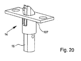
Fig. 15 , - Fig. 20
- eine perspektivische Ansicht eines zusammengesetzten Schaltschlosses,
- Fig. 21
bis 25 Darstellungen des Bewegungsablaufs des Schaltschlosses unter ei-nem Schließblech ohne Öffnung einer zugeordneten Tür,- Fig. 26
bis 32 - Darstellungen des Bewegungsablaufs des Schaltschlosses bei Bewegung einer zugeordneten Tür.
- Fig. 1
- a perspective view of a counter box according to the invention,
- Fig. 2
- a plan view of the mating box
Fig. 1 with omitted lock cover and extended bar connections, - Fig. 3
- one of the
Fig. 2 corresponding view with partially retracted bar connections, - Fig. 4
- one of the
Fig. 3 corresponding view of the counter box with fully retracted bar connections, - Fig. 5
- one of the
Fig. 4 corresponding view omitting various components of the lock mechanism, - Fig. 6
- a view of the counter box according to the invention with rods and one of the upper rod associated switching mechanism in the activated state,
- Fig. 7
- a view of the counter box
Fig. 6 omitting the rods and various components of the lock mechanism, - Fig. 8
- one of the
Fig. 6 corresponding view of the counter box with fully extended rods, - Fig. 9
- a view of the counter box
Fig. 8 omitting the rods and various components of the lock mechanism, - Fig. 10
- a schematic representation of a counter box with a switch lock,
- Fig. 11
- an enlarged view of the switching mechanism
Fig. 10 . - Fig. 12
- a representation of the individual parts of the bolt of the switching mechanism
Fig. 11 . - Fig. 13
- a perspective view of the individual components of the bolt immediately before installation,
- Fig. 14
- a perspective view of the composite bolt,
- Fig. 15
- a perspective view of the bolt guide of the switching mechanism according to the invention,
- Fig. 16
- a view of the bolt guide
Fig. 15 from the bottom, - Fig. 17
- a view of the bolt guide
Fig. 15 from the cuff side, - Fig. 18
- a side view of the bolt guide
Fig. 15 . - Fig. 19
- another side view of the bolt guide
Fig. 15 . - Fig. 20
- a perspective view of an assembled switch lock,
- Fig. 21
- to 25 representations of the sequence of movement of the switch lock under a strike plate without opening an associated door,
- Fig. 26 to 32
- Representations of the movement sequence of the switching mechanism when moving an associated door.
In
Der Gegenkasten 1 weist ein Schlossgehäuse 2 mit einem Schlosskasten 3 und einer Schlossdecke 4 auf. Stirnseitig ist am Schlosskasten 3 ein Stulp 5 vorgesehen. Im Stulp 5 befinden sich neben verschiedenen Befestigungsöffnungen eine Öffnung 6 für einen Fallenauswerfer 7 und eine Öffnung 8 für einen Riegelauswerfer 9. Bei dem Fallenauswerfer 7 und dem Riegelauswerfer 9 handelt es sich um charakteristische Bauteile eines Gegenkastens 1, die bei einem Einsteckschloss nicht vorgesehen sind. Statt dessen weist das Einsteckschloss eine Falle und einen Riegel auf.The
Weiterhin weist der Gegenkasten 1 zwei Stangenanschlüsse 10, 11, nämlich einen oberen Stangenanschluss 10 und einen unteren Stangenanschluss 11, auf, die jeweils zum Anschluss einer Stange 12, 13 vorgesehen sind. Die Stangen 12, 13 sind durch die nicht dargestellte Tür geführt und greifen endseitig in entsprechende Öffnungen von Schließblechen am Rahmen der Tür bzw. Boden ein. Bei den in den
Weiterhin weist der Gegenkasten ein eine Schaltnuss 17 auf, die über nicht dargestellte Drücker aktiv betätigt wird. Durch Betätigung der Schaltnuss 17 werden zum einen über die Schlossmechanik die Stangenanschlüssse 10, 11 von ihrer ausgefahrenen Stellung, die in den
Der Schwenkhebel 19, der im dargestellten Ausführungsbeispiel letztlich eine Sperrfunktion hat und an sich als Sperrhebel fungiert, worauf vorliegend jedoch nicht weiter eingegangen wird, ist schwenkbar gelagert und weist ein oberes Ende 20 und eine unteres Ende 21 auf. Zum Einziehen des oberen Stangenanschlusses 10 wirkt ein an einem Arm 22 der Schaltnuss 17 vorgesehener Betätigungsabschnitt 23, bei dem es sich vorliegend um einen Dorn handelt, auf eine Ablauffläche 24 am oberen Ende 20 des Schwenkhebels 19. Hierdurch wird der Schwenkhebel 19 herabgeschwenkt und der obere Stangenanschluss 10 eingezogen, wie sich dies aus einem Vergleich der
Der untere Stangenanschluss 11 ist mit einer Zugstange 25 verbunden und Ober diese mit der Schaltnuss 17 gekoppelt. Hierzu ist am oberen Ende der Zugstange 25 ein Angriffsabschnitt, vorliegend in Form eines Dorns 26, vorgesehen, der von einem in
Gleichzeitig mit dem Einziehen der Stangenanschlüsse 10, 11 werden bei Betätigung der Schaltnuss 17 der Fallenauswerfer 7 und der Riegelauswerfer 9 aus ihrer in
Vorgesehen ist nun, dass die Schlossmechanik des Gegenkastens 1 derart ausgebildet ist, dass zum Verriegeln der Stangen 12, 13 zunächst nur der obere Stangenanschluss 10 ausfährt, während der untere Stangenanschluss 11 in der eingezogenen Stellung über eine Sperreinrichtung 31 gesperrt ist. Erst nach Erreichen einer vorgegebenen Ausfahrstellung des oberen Stangenanschlusses 10, das heißt wenn die Tür in die geschlossene Stellung geschwenkt worden ist und die Stangen 12, 13 in einer Flucht mit den zugehörigen Schließblechen am Rahmen der Tür und am Boden sind, wird die Sperreinrichtung 30 entsperrt und der untere Stangenanschluss 11 aus seiner eingezogenen Stellung freigegeben. Hierdurch ergibt sich eine verzögerte Ausfahrbewegung des unteren Stangenanschlusses 11 gegenüber dem oberen Stangenanschluss, worauf nachfolgend noch näher eingegangen wird.It is now provided that the lock mechanism of the
Die Sperreinrichtung 31 weist vorliegend einen schwenkbar gelagerten Sperrhebel 32 auf, der über eine Feder 33 in Richtung auf die Zugstange 25 bzw. den Stulp 5 des Gegenkastens 1 federbelastet ist. Der Sperrhebel 32 weist an seinem freien Ende einen Gegenanschlag in Form eines Dorns 34 auf. Zum Dorn 34 korrespondiert ein Anschlag in Form einer verlängerten Nase 35 an der Zugstange 25. Die Nase 35 weist einen unterseitigen Anlageabschnitt 36 und eine oberseitige Auflaufschräge 37 auf.The locking
Bei dem in
Während nach dem durch die Feder 38 unterstützten Zurückschwenken bzw. -drehen der Schaltnuss 17 der untere Stangenanschluss 11 aufgrund der Sperreinrichtung 31 bzw. der Anlage der Nase 35 auf dem Dorn 34 gesperrt ist, fährt der obere Stangenanschluss 10 zumindest teilweise wieder aus. Damit der obere Stangenanschluss 10 nicht vollständig ausfährt, ist bei der in
Wird die betreffende Tür nun in die Schließstellung geschwenkt, schlägt der Riegel 15 des aktivierten Schaltschlosses 14 zunächst am Schließblech im Türrahmen an, wird aktiviert und taucht bei der abschließenden Schwenkbewegung der Tür in die Öffnung des nicht dargestellten Schließblechs im Rahmen ein. Dabei wird der obere Stangenanschluss 10 nach oben bewegt. In diesem Zusammenhang wird auf den oberen Teil der Darstellung gemäß
Der Entsperrhebel 40 selbst ist grundsätzlich als solcher nicht federbelastet. Der Entsperrhebel 40 liegt aufgrund seiner Eigengewichtskraft stets am Dorn 34 des Sperrhebels 32 an und wird entweder vom federunterstützten Sperrhebel 32 oder aber vom Schwenkhebel 19 bewegt.The unlocking
Aus
In
In
Vorgesehen ist dabei, dass am Riegel 15 ein Rasthebel 109 schwenkbar gelagert ist, der zum Zusammenwirken mit der Riegelführung 107 vorgesehen ist. Dabei wirkt der Rasthebel 109 zwischen der Rückzugstellung des Riegels 15, wie sie beispielsweise in den
In den
Der untere Teil des Riegels 15 weist eine Aufnahme 117 zur Anordnung der Treibstange 12 auf. Riegel 15 ist eine Öffnung 118 vorgesehen, die in die Aufnahme 117 mündet, so dass das korrekte Einstecken der Treibstange 12 in die Aufnahme optisch überprüft werden kann.The lower part of the
Der Rasthebel 109 weist, wie sich insbesondere aus
In den
Im Übrigen befindet sich in der Riegelhülse 122 am Übergang zum Stulp 121 eine Durchgriffsöffnung 127, die einen Eingriff des Rasthebels 109 an den Stulp 121 über die Rastausnehmung 120 ermöglicht.Incidentally, in the locking
Wie sich im Übrigen insbesondere aus den
Auf der Ausschwenkseite 119 des Rasthebels 109 befindet sich im Übrigen im Anschluss an die Rastausnehmung 120 ein Überbrückungsbereich 130, der letztlich zur Überbrückung des Spalts 131 zwischen dem Stulp 121 und dem Schließblech 105 vorgesehen ist. Der Überbrückungsbereich 130 geht über eine Einführschräge 132 in eine gerundete Spitze 133 über, die das Einführen des Rasthebels 109 in die Öffnung 134 des Schließblechs 104 gewährleistet.On the
Im Übrigen ergibt sich aus den einzelnen Darstellungen, dass zwischen der Riegelführung 107 und dem Riegel 15 kein Federelement vorgesehen ist, um den Riegel 15 aus der Rückzugstellung in die Verriegelungsstellung zu bewegen. Zwar ist der Riegel 15 zur Bewegung in Verriegelungsstellung federbelastet, die Federbelastung wird jedoch außerhalb des Schaltschlosses 14 aufgebracht, nämlich innerhalb des Gegenkastens 1, wobei die Federkraft dabei über die Treibstange 12 auf den Riegel 15 übertragen wird.Incidentally, it follows from the individual representations that no spring element is provided between the
Nachfolgend wird auf die Funktion des Schaltschlosses 14 anhand der
In
In
Die weitere Abwärtsbewegung des Riegels 15, hervorgerufen durch eine entsprechende Betätigung über den nicht dargestellten Drücker des Gegenkastens 1, führt zu der in
Wird nun der nicht dargestellte Drücker am Gegenkasten 1 wieder nach oben bewegt, wird diese Bewegung über die Treibstange 12 auf den Riegel 15 übertragen. In
Die weitere Bewegung des Drückers zurück in den Ursprungszustand - in der Regel bei horizontal angeordnetem Drückergriff - führt den Riegel 15 zu der in
In den
In
Anschließend wird der Drücker in seine Normal- oder Ursprungsstellung zurückbewegt. Dies führt zu einem Ausfahren des Riegels 15 gegenüber der Riegelführung 107.
Im Folgenden wird die Tür erneut geschlossen. Kurz vor Erreichen der Schließstellung der Tür schlägt der Riegel 15 mit der Fallenschräge 110 an der Randkante des Schließblechs 105 an. Dieser Zustand ist in
Durch die weitere Schwenkbewegung der Tür wird der Riegel 15 über die Fallenschräge 110 in eine Abwärtsbewegung relativ zur Riegelführung 107 gezwungen. Parallel zur Abwärtsbewegung des Riegels 5 wird der Rasthebel 109 über die Auflaufschräge 122 zu einem Hineinschwenken in die Hebelaufnahme 113 gezwungen. Dies ist in
Bei einer weiteren Schließbewegung der Tür wird der Riegel 15, sobald er sich vollständig unterhalb der Öffnung 134 im Schließblech 105 befindet, durch die Federkraft der im Gegenkasten 1 vorgesehenen, nicht dargestellten Feder nach oben gedrückt. Dabei ergibt sich zunächst der in
- 11
- GegenkastenStrike box
- 22
- Schlossgehäuselock housing
- 33
- Schlosskastenlock case
- 44
- Schlossdeckelock cover
- 55
- Stulpstulp
- 66
- Öffnungopening
- 77
- FallenauswerferFallenauswerfer
- 88th
- Öffnungopening
- 99
- RiegelauswerferRiegelauswerfer
- 1010
- oberer Stangenanschlussupper bar connection
- 1111
- unterer Stangenanschlusslower bar connection
- 1212
- obere Stangeupper bar
- 1313
- untere Stangelower bar
- 1414
- Schaltschlossswitch lock
- 1515
- Riegelbars
- 1616
- Führungguide
- 1717
- Schaltnussswitching nut
- 1818
- Gestängelinkage
- 1919
- Schwenkhebelpivoting lever
- 2020
- oberes Endetop end
- 2121
- unteres Endelower end
- 2222
- Armpoor
- 2323
- Betätigungsabschnittactuating section
- 2424
- Ablaufflächedrainage area
- 2525
- Zugstangepull bar
- 2626
- Dornmandrel
- 2727
- Armpoor
- 2828
- Gestängelinkage
- 2929
- Dornmandrel
- 3030
- Ablaufflächedrainage area
- 3131
- Sperreinrichtunglocking device
- 3232
- Sperrhebellocking lever
- 3333
- Federfeather
- 3434
- Dornmandrel
- 3535
- Nasenose
- 3636
- Anlageabschnittcontact section
- 3737
- Auflaufschrägeapproach ramp
- 3838
- Federfeather
- 3939
- Stulpstulp
- 4040
- Entsperrhebelrelease lever
- 4141
- LanglochLong hole
- 4242
- Dornmandrel
- 4343
- oberes Endetop end
- 4444
- unteres Endelower end
- 105105
- Schließblechstriking plate
- 107107
- Riegelführungbolt guide
- 109109
- Rasthebellocking lever
- 110110
- Fallenschrägecatch slope
- 111111
- Abflachungflattening
- 112112
- Anschlagattack
- 113113
- Hebelaufnahmelever accommodation
- 114114
- Lagerstiftbearing pin
- 115115
- Bohrungdrilling
- 116116
- Bohrungdrilling
- 117117
- Aufnahmeadmission
- 118118
- Öffnungopening
- 119119
- AusschwenkseiteAusschwenkseite
- 120120
- Rastausnehmungrecess
- 120a120a
- Auflaufschrägeapproach ramp
- 121121
- Stulpstulp
- 122122
- Riegelhülselocking sleeve
- 123123
- Schrauböffnungscrew opening
- 124124
- StulpöffnungStulpöffnung
- 125125
- Abflachungflattening
- 126126
- Anschlagattack
- 127127
- DurchgriffsöffnungThrough opening
- 128128
- Schraubenfedercoil spring
- 129129
- EinschwenkseiteEinschwenkseite
- 130130
- Überbrückungsbereichbridging region
- 131131
- Spaltgap
- 132132
- Einführschrägechamfer
- 133133
- Spitzetop
- 134134
- Öffnungopening
Claims (15)
dadurch gekennzeichnet,
dass dem oberen Stangenanschluss (11) ein Schaltschloss (14) mit Riegel (15) zugeordnet ist, das zur Schaltung von einem aktivierten Zustand insbesondere mit geringerem Riegelüberstand in einen verriegelten Zustand insbesondere mit maximalem Riegelüberstand vorgesehen ist und dass die Schlossmechanik derart ausgebildet ist, dass die Freigabe des unteren Stangenanschlusses (11) erst eingeleitet wird, wenn das Schaltschloss (14) von dem aktivierten Zustand in den verriegelten Zustand schaltet.Counter box (1) or mortise lock, with an upper bar connection (10) for connecting an upper bar (12), a lower bar connection (11) for connection of a lower bar (13) and a lock nut (17) for actuation lock mechanism for retracting and extending the rod terminals (10, 11), wherein the lock mechanism is designed such that for locking the rods (12, 13) initially only the upper rod terminal (10) extends, while the lower rod terminal (11) in the retracted position via a Locking device (31) is locked and wherein only after reaching a predetermined extended position of the upper bar connection (10) the locking device (31) unlocked and the lower bar connection (11) is released from the retracted position and extends, so that a delayed extension movement of the lower Bar connection (11) opposite the upper bar connection (10),
characterized,
in that a switch lock (14) with latch (15) is assigned to the upper bar connection (11), which is provided for switching from an activated state, in particular with a smaller bar projection, into a locked state, in particular with maximum bar projection, and in that the lock mechanism is designed such that the release of the lower bar connection (11) is only initiated when the switching mechanism (14) switches from the activated state to the locked state.
Priority Applications (1)
| Application Number | Priority Date | Filing Date | Title |
|---|---|---|---|
| PL14000107T PL2754801T5 (en) | 2013-01-11 | 2014-01-13 | Strike box or mortise lock |
Applications Claiming Priority (2)
| Application Number | Priority Date | Filing Date | Title |
|---|---|---|---|
| DE102013000355 | 2013-01-11 | ||
| DE102013001821.8A DE102013001821A1 (en) | 2013-01-11 | 2013-02-04 | Counter box or mortise lock |
Publications (4)
| Publication Number | Publication Date |
|---|---|
| EP2754801A2 true EP2754801A2 (en) | 2014-07-16 |
| EP2754801A3 EP2754801A3 (en) | 2015-07-22 |
| EP2754801B1 EP2754801B1 (en) | 2016-10-12 |
| EP2754801B2 EP2754801B2 (en) | 2019-07-10 |
Family
ID=49955884
Family Applications (1)
| Application Number | Title | Priority Date | Filing Date |
|---|---|---|---|
| EP14000107.4A Active EP2754801B2 (en) | 2013-01-11 | 2014-01-13 | Strike box or mortise lock |
Country Status (3)
| Country | Link |
|---|---|
| EP (1) | EP2754801B2 (en) |
| DE (1) | DE102013001821A1 (en) |
| PL (1) | PL2754801T5 (en) |
Cited By (1)
| Publication number | Priority date | Publication date | Assignee | Title |
|---|---|---|---|---|
| WO2015144785A1 (en) | 2014-03-25 | 2015-10-01 | Assa Abloy Sicherheitstechnik Gmbh | Switch lock for locking bar with time-delay function |
Families Citing this family (1)
| Publication number | Priority date | Publication date | Assignee | Title |
|---|---|---|---|---|
| DE202015008574U1 (en) | 2015-12-03 | 2016-01-26 | Wilh. Schlechtendahl & Söhne GmbH & Co. KG | Strike box |
Citations (1)
| Publication number | Priority date | Publication date | Assignee | Title |
|---|---|---|---|---|
| DE3903633A1 (en) | 1989-02-08 | 1990-08-09 | Fuhr Carl Gmbh & Co | DRIVE ROD LOCK |
Family Cites Families (24)
| Publication number | Priority date | Publication date | Assignee | Title |
|---|---|---|---|---|
| FR2482649A1 (en) | 1980-05-14 | 1981-11-20 | Parlebas Gerard | Emergency door release bar - is carried by facing strip which attaches to mounting surface on door |
| DE9104553U1 (en) | 1991-04-13 | 1991-06-06 | Bks Gmbh, 5620 Velbert, De | |
| IT1259256B (en) | 1992-03-24 | 1996-03-11 | Italiana Serrature Affini | COUNTERLOCK FOR TWO LEAF SECURITY DOORS |
| PL181353B1 (en) | 1995-10-31 | 2001-07-31 | Hoermann Kg Freisen | Locking device |
| US5816017A (en) | 1996-02-02 | 1998-10-06 | Yale Security Inc. | Fire retardant door and exit device for same |
| DE19626745C1 (en) | 1996-07-03 | 1997-10-16 | Dorma Gmbh & Co Kg | Self-securing panic door lock with spring-loaded cruciform latch |
| DE19652601C1 (en) | 1996-12-18 | 1998-06-25 | Dorma Gmbh & Co Kg | Unlocking and locking for a door with a passive leaf and an active leaf |
| GB9814262D0 (en) * | 1998-07-02 | 1998-09-02 | Nemef B V | Automatic door lock |
| DE29909660U1 (en) | 1999-06-02 | 1999-08-05 | Gretsch Unitas Gmbh | Door lock |
| DE10318352B3 (en) | 2003-04-23 | 2004-10-14 | Wilka Schließtechnik GmbH | Switching lock for a door has clamping elements formed as clamping tappets guided in guiding grooves of a guiding sleeve |
| DE102004009973B4 (en) | 2004-03-01 | 2007-03-22 | Wilh. Schlechtendahl & Söhne GmbH & Co KG | Counter box for a panic door lock |
| ITBO20050013A1 (en) | 2005-01-13 | 2006-07-14 | Cisa Spa | NOZZLE FOR SECONDARY DOOR OF FIREPROOF DOORS |
| DE102006030552A1 (en) | 2005-07-14 | 2007-01-18 | Kfv Karl Fliether Gmbh & Co. Kg | Escape door lock |
| DE202006001383U1 (en) | 2006-01-27 | 2006-04-13 | Bks Gmbh | Shot-bolt lock |
| DE202006005051U1 (en) | 2006-03-21 | 2007-03-08 | Gretsch-Unitas GmbH Baubeschläge | Lock e.g. mortise lock, for door, has safety catch with locking unit that holds catch in partially extended intermediate position, and blocking unit that is provided in intermediate position, is connected to rod and is controlled by catch |
| DE102007012613B4 (en) | 2007-03-13 | 2018-03-08 | Dormakaba Deutschland Gmbh | panic lock |
| DE202010006955U1 (en) | 2010-05-19 | 2010-08-19 | Kfv Karl Fliether Gmbh & Co. Kg | Espagnolette lock with multiple latch links |
| US8523250B2 (en) | 2010-12-06 | 2013-09-03 | Lynn Chiung-Ling Chen | Top-and-bottom latch structure for lock |
| DE102011000553A1 (en) | 2011-02-08 | 2012-08-09 | Dorma Gmbh & Co Kg | Lock system for a double-leaf door system with panic function |
| DE202013001050U1 (en) | 2013-01-11 | 2013-03-25 | Wilh. Schlechtendahl & Söhne GmbH & Co. KG | Counter box or mortise lock |
| DE202013001052U1 (en) | 2013-01-11 | 2013-03-25 | Wilh. Schlechtendahl & Söhne GmbH & Co. KG | Strike box |
| DE202013001049U1 (en) | 2013-01-11 | 2013-03-25 | Wilh. Schlechtendahl & Söhne GmbH & Co. KG | Counter box or mortise lock |
| DE202013001051U1 (en) | 2013-01-11 | 2013-03-25 | Wilh. Schlechtendahl & Söhne GmbH & Co. KG | Strike box |
| DE202013001053U1 (en) | 2013-01-11 | 2013-03-25 | Wilh. Schlechtendahl & Söhne GmbH & Co. KG | Counter box or mortise lock |
-
2013
- 2013-02-04 DE DE102013001821.8A patent/DE102013001821A1/en not_active Ceased
-
2014
- 2014-01-13 EP EP14000107.4A patent/EP2754801B2/en active Active
- 2014-01-13 PL PL14000107T patent/PL2754801T5/en unknown
Patent Citations (1)
| Publication number | Priority date | Publication date | Assignee | Title |
|---|---|---|---|---|
| DE3903633A1 (en) | 1989-02-08 | 1990-08-09 | Fuhr Carl Gmbh & Co | DRIVE ROD LOCK |
Cited By (1)
| Publication number | Priority date | Publication date | Assignee | Title |
|---|---|---|---|---|
| WO2015144785A1 (en) | 2014-03-25 | 2015-10-01 | Assa Abloy Sicherheitstechnik Gmbh | Switch lock for locking bar with time-delay function |
Also Published As
| Publication number | Publication date |
|---|---|
| PL2754801T3 (en) | 2017-04-28 |
| DE102013001821A1 (en) | 2014-07-17 |
| EP2754801A3 (en) | 2015-07-22 |
| EP2754801B2 (en) | 2019-07-10 |
| PL2754801T5 (en) | 2019-12-31 |
| EP2754801B1 (en) | 2016-10-12 |
Similar Documents
| Publication | Publication Date | Title |
|---|---|---|
| EP1970507B1 (en) | Anti panic lock | |
| DE102009025469B3 (en) | Shoot bolt lock | |
| WO2017036795A1 (en) | Device for positioning two sliding doors and furniture | |
| EP0942135A1 (en) | Locking device | |
| EP0509217A1 (en) | Door lock with several bolts | |
| EP2754800B1 (en) | Strike box or mortise lock | |
| EP2754801B2 (en) | Strike box or mortise lock | |
| DE102015000606A1 (en) | Locking device for a pivotally mounted wing | |
| EP0381820B1 (en) | Espagnolette lock | |
| EP3122969B1 (en) | Locking rod/clamping lock | |
| EP3034728B1 (en) | Opening limiter device | |
| EP2746506B1 (en) | Trigger lock | |
| WO2017140573A1 (en) | Fitting assembly for the connection of a tilt and slide leaf | |
| DE202012012085U1 (en) | switch lock | |
| EP3112564A1 (en) | Self-locking latch lock | |
| DE202013001053U1 (en) | Counter box or mortise lock | |
| EP2453086B1 (en) | Connecting rod for the fixed leaf of double-leafed windows or doors without mullion | |
| DE102015015543B3 (en) | Strike box | |
| DE102014104101A1 (en) | Switch lock for locking bar | |
| AT502543A1 (en) | DEVICE FOR OPENING AND CLOSING A CLOSURE ELEMENT | |
| EP3628801A1 (en) | Lock device for a door | |
| EP3078791B1 (en) | Fixed lead lock, in particular panic lock | |
| DE102013013547A1 (en) | Lock with latch with unlocking pin | |
| EP3299556A1 (en) | Locking device for a pivoting mounted wing | |
| EP1905930B1 (en) | Spring catcher for balcony or terrace doors |
Legal Events
| Date | Code | Title | Description |
|---|---|---|---|
| PUAI | Public reference made under article 153(3) epc to a published international application that has entered the european phase |
Free format text: ORIGINAL CODE: 0009012 |
|
| 17P | Request for examination filed |
Effective date: 20140113 |
|
| AK | Designated contracting states |
Kind code of ref document: A2 Designated state(s): AL AT BE BG CH CY CZ DE DK EE ES FI FR GB GR HR HU IE IS IT LI LT LU LV MC MK MT NL NO PL PT RO RS SE SI SK SM TR |
|
| AX | Request for extension of the european patent |
Extension state: BA ME |
|
| PUAL | Search report despatched |
Free format text: ORIGINAL CODE: 0009013 |
|
| AK | Designated contracting states |
Kind code of ref document: A3 Designated state(s): AL AT BE BG CH CY CZ DE DK EE ES FI FR GB GR HR HU IE IS IT LI LT LU LV MC MK MT NL NO PL PT RO RS SE SI SK SM TR |
|
| AX | Request for extension of the european patent |
Extension state: BA ME |
|
| RIC1 | Information provided on ipc code assigned before grant |
Ipc: E05C 7/04 20060101ALN20150615BHEP Ipc: E05B 15/10 20060101ALN20150615BHEP Ipc: E05B 63/20 20060101AFI20150615BHEP Ipc: E05C 9/18 20060101ALN20150615BHEP Ipc: E05C 9/04 20060101ALI20150615BHEP |
|
| R17P | Request for examination filed (corrected) |
Effective date: 20151126 |
|
| RBV | Designated contracting states (corrected) |
Designated state(s): AL AT BE BG CH CY CZ DE DK EE ES FI FR GB GR HR HU IE IS IT LI LT LU LV MC MK MT NL NO PL PT RO RS SE SI SK SM TR |
|
| REG | Reference to a national code |
Ref country code: DE Ref legal event code: R079 Ref document number: 502014001653 Country of ref document: DE Free format text: PREVIOUS MAIN CLASS: E05C0009040000 Ipc: E05B0063200000 |
|
| GRAP | Despatch of communication of intention to grant a patent |
Free format text: ORIGINAL CODE: EPIDOSNIGR1 |
|
| RIC1 | Information provided on ipc code assigned before grant |
Ipc: E05C 7/04 20060101ALN20160304BHEP Ipc: E05C 9/18 20060101ALN20160304BHEP Ipc: E05B 63/20 20060101AFI20160304BHEP Ipc: E05C 9/04 20060101ALI20160304BHEP Ipc: E05B 15/10 20060101ALN20160304BHEP |
|
| INTG | Intention to grant announced |
Effective date: 20160323 |
|
| GRAS | Grant fee paid |
Free format text: ORIGINAL CODE: EPIDOSNIGR3 |
|
| GRAA | (expected) grant |
Free format text: ORIGINAL CODE: 0009210 |
|
| AK | Designated contracting states |
Kind code of ref document: B1 Designated state(s): AL AT BE BG CH CY CZ DE DK EE ES FI FR GB GR HR HU IE IS IT LI LT LU LV MC MK MT NL NO PL PT RO RS SE SI SK SM TR |
|
| REG | Reference to a national code |
Ref country code: GB Ref legal event code: FG4D Free format text: NOT ENGLISH |
|
| REG | Reference to a national code |
Ref country code: CH Ref legal event code: EP |
|
| REG | Reference to a national code |
Ref country code: AT Ref legal event code: REF Ref document number: 836671 Country of ref document: AT Kind code of ref document: T Effective date: 20161015 |
|
| REG | Reference to a national code |
Ref country code: IE Ref legal event code: FG4D Free format text: LANGUAGE OF EP DOCUMENT: GERMAN |
|
| REG | Reference to a national code |
Ref country code: DE Ref legal event code: R096 Ref document number: 502014001653 Country of ref document: DE |
|
| REG | Reference to a national code |
Ref country code: FR Ref legal event code: PLFP Year of fee payment: 4 |
|
| REG | Reference to a national code |
Ref country code: LT Ref legal event code: MG4D |
|
| REG | Reference to a national code |
Ref country code: NL Ref legal event code: MP Effective date: 20161012 |
|
| PG25 | Lapsed in a contracting state [announced via postgrant information from national office to epo] |
Ref country code: LV Free format text: LAPSE BECAUSE OF FAILURE TO SUBMIT A TRANSLATION OF THE DESCRIPTION OR TO PAY THE FEE WITHIN THE PRESCRIBED TIME-LIMIT Effective date: 20161012 |
|
| PG25 | Lapsed in a contracting state [announced via postgrant information from national office to epo] |
Ref country code: GR Free format text: LAPSE BECAUSE OF FAILURE TO SUBMIT A TRANSLATION OF THE DESCRIPTION OR TO PAY THE FEE WITHIN THE PRESCRIBED TIME-LIMIT Effective date: 20170113 Ref country code: NO Free format text: LAPSE BECAUSE OF FAILURE TO SUBMIT A TRANSLATION OF THE DESCRIPTION OR TO PAY THE FEE WITHIN THE PRESCRIBED TIME-LIMIT Effective date: 20170112 Ref country code: SE Free format text: LAPSE BECAUSE OF FAILURE TO SUBMIT A TRANSLATION OF THE DESCRIPTION OR TO PAY THE FEE WITHIN THE PRESCRIBED TIME-LIMIT Effective date: 20161012 Ref country code: LT Free format text: LAPSE BECAUSE OF FAILURE TO SUBMIT A TRANSLATION OF THE DESCRIPTION OR TO PAY THE FEE WITHIN THE PRESCRIBED TIME-LIMIT Effective date: 20161012 |
|
| PG25 | Lapsed in a contracting state [announced via postgrant information from national office to epo] |
Ref country code: FI Free format text: LAPSE BECAUSE OF FAILURE TO SUBMIT A TRANSLATION OF THE DESCRIPTION OR TO PAY THE FEE WITHIN THE PRESCRIBED TIME-LIMIT Effective date: 20161012 Ref country code: NL Free format text: LAPSE BECAUSE OF FAILURE TO SUBMIT A TRANSLATION OF THE DESCRIPTION OR TO PAY THE FEE WITHIN THE PRESCRIBED TIME-LIMIT Effective date: 20161012 Ref country code: ES Free format text: LAPSE BECAUSE OF FAILURE TO SUBMIT A TRANSLATION OF THE DESCRIPTION OR TO PAY THE FEE WITHIN THE PRESCRIBED TIME-LIMIT Effective date: 20161012 Ref country code: PT Free format text: LAPSE BECAUSE OF FAILURE TO SUBMIT A TRANSLATION OF THE DESCRIPTION OR TO PAY THE FEE WITHIN THE PRESCRIBED TIME-LIMIT Effective date: 20170213 Ref country code: RS Free format text: LAPSE BECAUSE OF FAILURE TO SUBMIT A TRANSLATION OF THE DESCRIPTION OR TO PAY THE FEE WITHIN THE PRESCRIBED TIME-LIMIT Effective date: 20161012 Ref country code: HR Free format text: LAPSE BECAUSE OF FAILURE TO SUBMIT A TRANSLATION OF THE DESCRIPTION OR TO PAY THE FEE WITHIN THE PRESCRIBED TIME-LIMIT Effective date: 20161012 Ref country code: IS Free format text: LAPSE BECAUSE OF FAILURE TO SUBMIT A TRANSLATION OF THE DESCRIPTION OR TO PAY THE FEE WITHIN THE PRESCRIBED TIME-LIMIT Effective date: 20170212 |
|
| REG | Reference to a national code |
Ref country code: DE Ref legal event code: R026 Ref document number: 502014001653 Country of ref document: DE |
|
| PLBI | Opposition filed |
Free format text: ORIGINAL CODE: 0009260 |
|
| PG25 | Lapsed in a contracting state [announced via postgrant information from national office to epo] |
Ref country code: RO Free format text: LAPSE BECAUSE OF FAILURE TO SUBMIT A TRANSLATION OF THE DESCRIPTION OR TO PAY THE FEE WITHIN THE PRESCRIBED TIME-LIMIT Effective date: 20161012 Ref country code: EE Free format text: LAPSE BECAUSE OF FAILURE TO SUBMIT A TRANSLATION OF THE DESCRIPTION OR TO PAY THE FEE WITHIN THE PRESCRIBED TIME-LIMIT Effective date: 20161012 Ref country code: SK Free format text: LAPSE BECAUSE OF FAILURE TO SUBMIT A TRANSLATION OF THE DESCRIPTION OR TO PAY THE FEE WITHIN THE PRESCRIBED TIME-LIMIT Effective date: 20161012 Ref country code: CZ Free format text: LAPSE BECAUSE OF FAILURE TO SUBMIT A TRANSLATION OF THE DESCRIPTION OR TO PAY THE FEE WITHIN THE PRESCRIBED TIME-LIMIT Effective date: 20161012 Ref country code: DK Free format text: LAPSE BECAUSE OF FAILURE TO SUBMIT A TRANSLATION OF THE DESCRIPTION OR TO PAY THE FEE WITHIN THE PRESCRIBED TIME-LIMIT Effective date: 20161012 |
|
| 26 | Opposition filed |
Opponent name: DORMAKABA DEUTSCHLAND GMBH Effective date: 20170712 |
|
| PG25 | Lapsed in a contracting state [announced via postgrant information from national office to epo] |
Ref country code: BG Free format text: LAPSE BECAUSE OF FAILURE TO SUBMIT A TRANSLATION OF THE DESCRIPTION OR TO PAY THE FEE WITHIN THE PRESCRIBED TIME-LIMIT Effective date: 20170112 Ref country code: SM Free format text: LAPSE BECAUSE OF FAILURE TO SUBMIT A TRANSLATION OF THE DESCRIPTION OR TO PAY THE FEE WITHIN THE PRESCRIBED TIME-LIMIT Effective date: 20161012 |
|
| PLAX | Notice of opposition and request to file observation + time limit sent |
Free format text: ORIGINAL CODE: EPIDOSNOBS2 |
|
| PG25 | Lapsed in a contracting state [announced via postgrant information from national office to epo] |
Ref country code: MC Free format text: LAPSE BECAUSE OF FAILURE TO SUBMIT A TRANSLATION OF THE DESCRIPTION OR TO PAY THE FEE WITHIN THE PRESCRIBED TIME-LIMIT Effective date: 20161012 |
|
| REG | Reference to a national code |
Ref country code: IE Ref legal event code: MM4A |
|
| PG25 | Lapsed in a contracting state [announced via postgrant information from national office to epo] |
Ref country code: LU Free format text: LAPSE BECAUSE OF NON-PAYMENT OF DUE FEES Effective date: 20170113 Ref country code: SI Free format text: LAPSE BECAUSE OF FAILURE TO SUBMIT A TRANSLATION OF THE DESCRIPTION OR TO PAY THE FEE WITHIN THE PRESCRIBED TIME-LIMIT Effective date: 20161012 |
|
| PLBB | Reply of patent proprietor to notice(s) of opposition received |
Free format text: ORIGINAL CODE: EPIDOSNOBS3 |
|
| REG | Reference to a national code |
Ref country code: FR Ref legal event code: PLFP Year of fee payment: 5 |
|
| PG25 | Lapsed in a contracting state [announced via postgrant information from national office to epo] |
Ref country code: IE Free format text: LAPSE BECAUSE OF NON-PAYMENT OF DUE FEES Effective date: 20170113 |
|
| GBPC | Gb: european patent ceased through non-payment of renewal fee |
Effective date: 20180113 |
|
| PG25 | Lapsed in a contracting state [announced via postgrant information from national office to epo] |
Ref country code: MT Free format text: LAPSE BECAUSE OF FAILURE TO SUBMIT A TRANSLATION OF THE DESCRIPTION OR TO PAY THE FEE WITHIN THE PRESCRIBED TIME-LIMIT Effective date: 20161012 |
|
| PG25 | Lapsed in a contracting state [announced via postgrant information from national office to epo] |
Ref country code: GB Free format text: LAPSE BECAUSE OF NON-PAYMENT OF DUE FEES Effective date: 20180113 |
|
| REG | Reference to a national code |
Ref country code: CH Ref legal event code: PK Free format text: BERICHTIGUNGEN |
|
| REG | Reference to a national code |
Ref country code: CH Ref legal event code: PK Free format text: BERICHTIGUNGEN |
|
| RIC2 | Information provided on ipc code assigned after grant |
Ipc: E05C 9/04 20060101ALI20181130BHEP Ipc: E05C 9/18 20060101ALN20181130BHEP Ipc: E05C 7/04 20060101ALN20181130BHEP Ipc: E05B 63/20 20060101AFI20181130BHEP Ipc: E05B 15/10 20060101ALN20181130BHEP |
|
| RIC2 | Information provided on ipc code assigned after grant |
Ipc: E05C 9/18 20060101ALN20181207BHEP Ipc: E05B 15/10 20060101ALN20181207BHEP Ipc: E05C 7/04 20060101ALN20181207BHEP Ipc: E05C 9/04 20060101ALI20181207BHEP Ipc: E05B 63/20 20060101AFI20181207BHEP |
|
| PUAH | Patent maintained in amended form |
Free format text: ORIGINAL CODE: 0009272 |
|
| STAA | Information on the status of an ep patent application or granted ep patent |
Free format text: STATUS: PATENT MAINTAINED AS AMENDED |
|
| REG | Reference to a national code |
Ref country code: CH Ref legal event code: AELC |
|
| PG25 | Lapsed in a contracting state [announced via postgrant information from national office to epo] |
Ref country code: HU Free format text: LAPSE BECAUSE OF FAILURE TO SUBMIT A TRANSLATION OF THE DESCRIPTION OR TO PAY THE FEE WITHIN THE PRESCRIBED TIME-LIMIT; INVALID AB INITIO Effective date: 20140113 |
|
| 27A | Patent maintained in amended form |
Effective date: 20190710 |
|
| AK | Designated contracting states |
Kind code of ref document: B2 Designated state(s): AL AT BE BG CH CY CZ DE DK EE ES FI FR GB GR HR HU IE IS IT LI LT LU LV MC MK MT NL NO PL PT RO RS SE SI SK SM TR |
|
| REG | Reference to a national code |
Ref country code: DE Ref legal event code: R102 Ref document number: 502014001653 Country of ref document: DE |
|
| PG25 | Lapsed in a contracting state [announced via postgrant information from national office to epo] |
Ref country code: CY Free format text: LAPSE BECAUSE OF NON-PAYMENT OF DUE FEES Effective date: 20161012 |
|
| PG25 | Lapsed in a contracting state [announced via postgrant information from national office to epo] |
Ref country code: MK Free format text: LAPSE BECAUSE OF FAILURE TO SUBMIT A TRANSLATION OF THE DESCRIPTION OR TO PAY THE FEE WITHIN THE PRESCRIBED TIME-LIMIT Effective date: 20161012 |
|
| PG25 | Lapsed in a contracting state [announced via postgrant information from national office to epo] |
Ref country code: TR Free format text: LAPSE BECAUSE OF FAILURE TO SUBMIT A TRANSLATION OF THE DESCRIPTION OR TO PAY THE FEE WITHIN THE PRESCRIBED TIME-LIMIT Effective date: 20161012 |
|
| PG25 | Lapsed in a contracting state [announced via postgrant information from national office to epo] |
Ref country code: AL Free format text: LAPSE BECAUSE OF FAILURE TO SUBMIT A TRANSLATION OF THE DESCRIPTION OR TO PAY THE FEE WITHIN THE PRESCRIBED TIME-LIMIT Effective date: 20161012 |
|
| PGFP | Annual fee paid to national office [announced via postgrant information from national office to epo] |
Ref country code: FR Payment date: 20230124 Year of fee payment: 10 |
|
| PGFP | Annual fee paid to national office [announced via postgrant information from national office to epo] |
Ref country code: PL Payment date: 20230105 Year of fee payment: 10 Ref country code: IT Payment date: 20230120 Year of fee payment: 10 Ref country code: BE Payment date: 20230119 Year of fee payment: 10 |
|
| P01 | Opt-out of the competence of the unified patent court (upc) registered |
Effective date: 20230613 |
|
| PGFP | Annual fee paid to national office [announced via postgrant information from national office to epo] |
Ref country code: AT Payment date: 20240122 Year of fee payment: 11 |
|
| PGFP | Annual fee paid to national office [announced via postgrant information from national office to epo] |
Ref country code: DE Payment date: 20240123 Year of fee payment: 11 Ref country code: CH Payment date: 20240201 Year of fee payment: 11 |