EP2754618A1 - Food container having nanostructured hydrophobic surface and manufacturing method thereof - Google Patents
Food container having nanostructured hydrophobic surface and manufacturing method thereof Download PDFInfo
- Publication number
- EP2754618A1 EP2754618A1 EP12829733.0A EP12829733A EP2754618A1 EP 2754618 A1 EP2754618 A1 EP 2754618A1 EP 12829733 A EP12829733 A EP 12829733A EP 2754618 A1 EP2754618 A1 EP 2754618A1
- Authority
- EP
- European Patent Office
- Prior art keywords
- nano
- thin film
- food container
- hydrophobic thin
- gas blocking
- Prior art date
- Legal status (The legal status is an assumption and is not a legal conclusion. Google has not performed a legal analysis and makes no representation as to the accuracy of the status listed.)
- Withdrawn
Links
Images




Classifications
-
- A—HUMAN NECESSITIES
- A47—FURNITURE; DOMESTIC ARTICLES OR APPLIANCES; COFFEE MILLS; SPICE MILLS; SUCTION CLEANERS IN GENERAL
- A47J—KITCHEN EQUIPMENT; COFFEE MILLS; SPICE MILLS; APPARATUS FOR MAKING BEVERAGES
- A47J47/00—Kitchen containers, stands or the like, not provided for in other groups of this subclass; Cutting-boards, e.g. for bread
- A47J47/02—Closed containers for foodstuffs
-
- B—PERFORMING OPERATIONS; TRANSPORTING
- B65—CONVEYING; PACKING; STORING; HANDLING THIN OR FILAMENTARY MATERIAL
- B65D—CONTAINERS FOR STORAGE OR TRANSPORT OF ARTICLES OR MATERIALS, e.g. BAGS, BARRELS, BOTTLES, BOXES, CANS, CARTONS, CRATES, DRUMS, JARS, TANKS, HOPPERS, FORWARDING CONTAINERS; ACCESSORIES, CLOSURES, OR FITTINGS THEREFOR; PACKAGING ELEMENTS; PACKAGES
- B65D25/00—Details of other kinds or types of rigid or semi-rigid containers
- B65D25/14—Linings or internal coatings
-
- A—HUMAN NECESSITIES
- A47—FURNITURE; DOMESTIC ARTICLES OR APPLIANCES; COFFEE MILLS; SPICE MILLS; SUCTION CLEANERS IN GENERAL
- A47G—HOUSEHOLD OR TABLE EQUIPMENT
- A47G19/00—Table service
- A47G19/02—Plates, dishes or the like
-
- B—PERFORMING OPERATIONS; TRANSPORTING
- B32—LAYERED PRODUCTS
- B32B—LAYERED PRODUCTS, i.e. PRODUCTS BUILT-UP OF STRATA OF FLAT OR NON-FLAT, e.g. CELLULAR OR HONEYCOMB, FORM
- B32B27/00—Layered products comprising a layer of synthetic resin
- B32B27/06—Layered products comprising a layer of synthetic resin as the main or only constituent of a layer, which is next to another layer of the same or of a different material
-
- B—PERFORMING OPERATIONS; TRANSPORTING
- B65—CONVEYING; PACKING; STORING; HANDLING THIN OR FILAMENTARY MATERIAL
- B65D—CONTAINERS FOR STORAGE OR TRANSPORT OF ARTICLES OR MATERIALS, e.g. BAGS, BARRELS, BOTTLES, BOXES, CANS, CARTONS, CRATES, DRUMS, JARS, TANKS, HOPPERS, FORWARDING CONTAINERS; ACCESSORIES, CLOSURES, OR FITTINGS THEREFOR; PACKAGING ELEMENTS; PACKAGES
- B65D1/00—Rigid or semi-rigid containers having bodies formed in one piece, e.g. by casting metallic material, by moulding plastics, by blowing vitreous material, by throwing ceramic material, by moulding pulped fibrous material or by deep-drawing operations performed on sheet material
- B65D1/40—Details of walls
-
- B—PERFORMING OPERATIONS; TRANSPORTING
- B65—CONVEYING; PACKING; STORING; HANDLING THIN OR FILAMENTARY MATERIAL
- B65D—CONTAINERS FOR STORAGE OR TRANSPORT OF ARTICLES OR MATERIALS, e.g. BAGS, BARRELS, BOTTLES, BOXES, CANS, CARTONS, CRATES, DRUMS, JARS, TANKS, HOPPERS, FORWARDING CONTAINERS; ACCESSORIES, CLOSURES, OR FITTINGS THEREFOR; PACKAGING ELEMENTS; PACKAGES
- B65D65/00—Wrappers or flexible covers; Packaging materials of special type or form
- B65D65/38—Packaging materials of special type or form
- B65D65/40—Applications of laminates for particular packaging purposes
-
- B—PERFORMING OPERATIONS; TRANSPORTING
- B65—CONVEYING; PACKING; STORING; HANDLING THIN OR FILAMENTARY MATERIAL
- B65D—CONTAINERS FOR STORAGE OR TRANSPORT OF ARTICLES OR MATERIALS, e.g. BAGS, BARRELS, BOTTLES, BOXES, CANS, CARTONS, CRATES, DRUMS, JARS, TANKS, HOPPERS, FORWARDING CONTAINERS; ACCESSORIES, CLOSURES, OR FITTINGS THEREFOR; PACKAGING ELEMENTS; PACKAGES
- B65D81/00—Containers, packaging elements, or packages, for contents presenting particular transport or storage problems, or adapted to be used for non-packaging purposes after removal of contents
- B65D81/24—Adaptations for preventing deterioration or decay of contents; Applications to the container or packaging material of food preservatives, fungicides, pesticides or animal repellants
-
- C—CHEMISTRY; METALLURGY
- C23—COATING METALLIC MATERIAL; COATING MATERIAL WITH METALLIC MATERIAL; CHEMICAL SURFACE TREATMENT; DIFFUSION TREATMENT OF METALLIC MATERIAL; COATING BY VACUUM EVAPORATION, BY SPUTTERING, BY ION IMPLANTATION OR BY CHEMICAL VAPOUR DEPOSITION, IN GENERAL; INHIBITING CORROSION OF METALLIC MATERIAL OR INCRUSTATION IN GENERAL
- C23C—COATING METALLIC MATERIAL; COATING MATERIAL WITH METALLIC MATERIAL; SURFACE TREATMENT OF METALLIC MATERIAL BY DIFFUSION INTO THE SURFACE, BY CHEMICAL CONVERSION OR SUBSTITUTION; COATING BY VACUUM EVAPORATION, BY SPUTTERING, BY ION IMPLANTATION OR BY CHEMICAL VAPOUR DEPOSITION, IN GENERAL
- C23C16/00—Chemical coating by decomposition of gaseous compounds, without leaving reaction products of surface material in the coating, i.e. chemical vapour deposition [CVD] processes
- C23C16/22—Chemical coating by decomposition of gaseous compounds, without leaving reaction products of surface material in the coating, i.e. chemical vapour deposition [CVD] processes characterised by the deposition of inorganic material, other than metallic material
- C23C16/30—Deposition of compounds, mixtures or solid solutions, e.g. borides, carbides, nitrides
- C23C16/40—Oxides
- C23C16/401—Oxides containing silicon
-
- C—CHEMISTRY; METALLURGY
- C23—COATING METALLIC MATERIAL; COATING MATERIAL WITH METALLIC MATERIAL; CHEMICAL SURFACE TREATMENT; DIFFUSION TREATMENT OF METALLIC MATERIAL; COATING BY VACUUM EVAPORATION, BY SPUTTERING, BY ION IMPLANTATION OR BY CHEMICAL VAPOUR DEPOSITION, IN GENERAL; INHIBITING CORROSION OF METALLIC MATERIAL OR INCRUSTATION IN GENERAL
- C23C—COATING METALLIC MATERIAL; COATING MATERIAL WITH METALLIC MATERIAL; SURFACE TREATMENT OF METALLIC MATERIAL BY DIFFUSION INTO THE SURFACE, BY CHEMICAL CONVERSION OR SUBSTITUTION; COATING BY VACUUM EVAPORATION, BY SPUTTERING, BY ION IMPLANTATION OR BY CHEMICAL VAPOUR DEPOSITION, IN GENERAL
- C23C16/00—Chemical coating by decomposition of gaseous compounds, without leaving reaction products of surface material in the coating, i.e. chemical vapour deposition [CVD] processes
- C23C16/22—Chemical coating by decomposition of gaseous compounds, without leaving reaction products of surface material in the coating, i.e. chemical vapour deposition [CVD] processes characterised by the deposition of inorganic material, other than metallic material
- C23C16/30—Deposition of compounds, mixtures or solid solutions, e.g. borides, carbides, nitrides
- C23C16/40—Oxides
- C23C16/401—Oxides containing silicon
- C23C16/402—Silicon dioxide
-
- C—CHEMISTRY; METALLURGY
- C23—COATING METALLIC MATERIAL; COATING MATERIAL WITH METALLIC MATERIAL; CHEMICAL SURFACE TREATMENT; DIFFUSION TREATMENT OF METALLIC MATERIAL; COATING BY VACUUM EVAPORATION, BY SPUTTERING, BY ION IMPLANTATION OR BY CHEMICAL VAPOUR DEPOSITION, IN GENERAL; INHIBITING CORROSION OF METALLIC MATERIAL OR INCRUSTATION IN GENERAL
- C23C—COATING METALLIC MATERIAL; COATING MATERIAL WITH METALLIC MATERIAL; SURFACE TREATMENT OF METALLIC MATERIAL BY DIFFUSION INTO THE SURFACE, BY CHEMICAL CONVERSION OR SUBSTITUTION; COATING BY VACUUM EVAPORATION, BY SPUTTERING, BY ION IMPLANTATION OR BY CHEMICAL VAPOUR DEPOSITION, IN GENERAL
- C23C16/00—Chemical coating by decomposition of gaseous compounds, without leaving reaction products of surface material in the coating, i.e. chemical vapour deposition [CVD] processes
- C23C16/44—Chemical coating by decomposition of gaseous compounds, without leaving reaction products of surface material in the coating, i.e. chemical vapour deposition [CVD] processes characterised by the method of coating
-
- C—CHEMISTRY; METALLURGY
- C23—COATING METALLIC MATERIAL; COATING MATERIAL WITH METALLIC MATERIAL; CHEMICAL SURFACE TREATMENT; DIFFUSION TREATMENT OF METALLIC MATERIAL; COATING BY VACUUM EVAPORATION, BY SPUTTERING, BY ION IMPLANTATION OR BY CHEMICAL VAPOUR DEPOSITION, IN GENERAL; INHIBITING CORROSION OF METALLIC MATERIAL OR INCRUSTATION IN GENERAL
- C23C—COATING METALLIC MATERIAL; COATING MATERIAL WITH METALLIC MATERIAL; SURFACE TREATMENT OF METALLIC MATERIAL BY DIFFUSION INTO THE SURFACE, BY CHEMICAL CONVERSION OR SUBSTITUTION; COATING BY VACUUM EVAPORATION, BY SPUTTERING, BY ION IMPLANTATION OR BY CHEMICAL VAPOUR DEPOSITION, IN GENERAL
- C23C16/00—Chemical coating by decomposition of gaseous compounds, without leaving reaction products of surface material in the coating, i.e. chemical vapour deposition [CVD] processes
- C23C16/44—Chemical coating by decomposition of gaseous compounds, without leaving reaction products of surface material in the coating, i.e. chemical vapour deposition [CVD] processes characterised by the method of coating
- C23C16/50—Chemical coating by decomposition of gaseous compounds, without leaving reaction products of surface material in the coating, i.e. chemical vapour deposition [CVD] processes characterised by the method of coating using electric discharges
- C23C16/505—Chemical coating by decomposition of gaseous compounds, without leaving reaction products of surface material in the coating, i.e. chemical vapour deposition [CVD] processes characterised by the method of coating using electric discharges using radio frequency discharges
Definitions
- the present invention relates to a food container and a manufacturing method thereof, and more particularly, to a food container having a nano-structured hydrophobic surface having hydrophobicity and a gas blocking property, and a manufacturing method thereof.
- a food container which is used for storing food and the like, is mainly formed of a plastic material, such as polypropylene (PP) or polyethylene terephthalate (PET) by reason of manufacturing easiness and a low cost.
- PP polypropylene
- PET polyethylene terephthalate
- a plastic material having relatively low surface energy is a hydrophilic material having a contact angle of 50 to 80° with respect to pure water.
- a fact that a surface has hydrophilicity means that the surface prefers a contact with water to a contact with air, and water attached to the surface has a wide contact area with the surface and is not well separated from the surface. That is, food is stably attached to the surface.
- An object of the present invention is to provide a food container having a nano-structured hydrophobic surface capable of preventing a stain generated due to a contact of food containing water with a surface of the food container, decreasing food residual left on the surface of the food container, and preventing a harmful influence from the food container by minimizing a contact area of food and the food container, and a manufacturing method thereof.
- the present invention provides a food container made of a plastic material and having a nano-structured hydrophobic surface, including: a plurality of nano-structures formed on a surface of the food container; and a first hydrophobic thin film coated on an upper side of the surface, on which the nano-structures are formed.
- the food container may further include a gas blocking film formed between the surface of the food container and the first hydrophobic thin film.
- the food container may further include a second hydrophobic thin film formed between the surface of the food container and the gas blocking film.
- the nano-structure may have any one shape among a nano-pillar shape, a nano-rod shape, a nano-dot shape, and a nano-wire shape.
- the nano-structure may have a width of 1 to 100 nm and a height of 1 to 1000 nm.
- a contact angle of the first hydrophobic thin film may be equal to or larger than 90°, and contact angle hysteresis of the first hydrophobic thin film may be less than 30°.
- a sum of a thickness of the first hydrophobic thin film and a thickness of the gas blocking film may be a half of a height of the nano-structure or lower.
- a sum of a thickness of the first hydrophobic thin film, a thickness of the gas blocking film, and a thickness of the second hydrophobic thin film may be a half of a height of the nano-structure or lower.
- the first hydrophobic thin film is formed of hexamethyldisiloxane
- gas blocking film may be formed of silicon oxide.
- the second hydrophobic thin film may be formed of hexamethyldisiloxane
- gas blocking film and the first and second hydrophobic thin films may be discontinuously combined.
- gas blocking film and the first and second hydrophobic thin films may be continuously combined according to a continuous change in mutual chemical composition.
- a method of manufacturing a food container having a nano-structured hydrophobic surface of the present invention includes: forming a plurality of nano-structures on a surface of the food container formed of a plastic material; and coating a first hydrophobic thin film on an upper side of the surface, on which the nano-structures are formed.
- the method may further include coating a gas blocking film on the upper side of the surface, on which the nano-structures are formed, between the forming of the plurality of nano-structures and the coating of the first hydrophobic thin film.
- the method may further include coating a second hydrophobic thin film on the upper side of the surface, on which the nano-structures are formed, between the forming of the plurality of nano-structures and the coating of the gas blocking film.
- the nano-structure may have any one shape among a nano-pillar shape, a nano-rod shape, a nano-dot shape, and a nano-wire shape.
- the nano-structure may have a width of 1 to 100 nm and a height of 1 to 1000 nm.
- a contact angle of the first hydrophobic thin film may be equal to or larger than 90°, and contact angle hysteresis of the first hydrophobic thin film may be less than 30°.
- a sum of a thickness of the first hydrophobic thin film and a thickness of the gas blocking film may be a half of a height of the nano-structure or lower.
- a sum of a thickness of the first hydrophobic thin film, a thickness of the gas blocking film, and a thickness of the second hydrophobic thin film may be a half of a height of the nano-structure or lower.
- the first hydrophobic thin film may be formed of hexamethyldisiloxane
- the gas blocking film may be formed of silicon oxide.
- the second hydrophobic thin film may be formed of hexamethyldisiloxane
- gas blocking film and the first and second hydrophobic thin films may be discontinuously combined.
- gas blocking film and the first and second hydrophobic thin films may be continuously combined according to a continuous change in mutual chemical composition.
- the food container having the nano-structured hydrophobic surface capable of preventing a stain generated due to a contact of food containing water with a surface of the food container, decreasing food residual left on the surface of the food container, and preventing a harmful influence from the food container by minimizing a contact area of food and the food container, and a manufacturing method thereof.
- the food container having the nano-structured hydrophobic surface capable of having excellent gas blocking performance, as well as hydrophobicity, by additionally forming the gas blocking film, and the manufacturing method thereof.
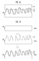
- FIG. 1A is a diagram illustrating a food container having a nano-structured hydrophobic surface according to a first exemplary embodiment of the present invention.
- a food container 100 having a nano-structured hydrophobic surface (hereinafter, referred to as a "food container") according to a first exemplary embodiment of the present invention includes a plurality of nano-structures 20 and a first hydrophobic thin film 30.
- the food container 100 is formed of a plastic material, such as polypropylene (PP), polyethylene terephthalate (PET), polyethylene (PE), polystyrene (PS) and the like.
- PP polypropylene
- PET polyethylene terephthalate
- PE polyethylene
- PS polystyrene
- the food container 100 has hydrophilicity, so that food is attached to the food container 100) of the food container 100 formed of the plastic material
- the food container 100 according to the exemplary embodiment is formed of the plurality of nano-structures 20 on a surface thereof.
- an air membrane is stably positioned in a space between the respective nano structures 20, so that the surface of the food container 100 has a very small contact area with food 60 containing water. Accordingly, the surface of the food container 100 has the hydrophobicity.
- a first hydrophobic thin film 30 may be coated on an upper side of the surface of the food container 100, on which the nano-structures are formed.
- the first hydrophobic thin film 30 may be implemented by a material, which has low surface energy to have hydrophobicity, and may be preferably implemented by hexamethyldisiloxane (HMDSO), but may also adopt polytetrafluoroethylene (PTFE) or alkyl keton dimer (AKD), which is a conventionally well-known hydrophobic thin film.
- HMDSO hexamethyldisiloxane
- PTFE polytetrafluoroethylene
- ALD alkyl keton dimer
- a contact angle of a water drop, which is in contact with the first hydrophobic thin film 30, is 90° or more through the forming of the nano-structures 20 and the first hydrophobic thin film 30, and contact angle hysteresis is also less than 30°.
- a contact angle is defined as an angle between a liquid surface and a solid surface in a liquid and a solid which are in contact with each other, and is generally represented by an angle formed between a tangent line from a contact point of a droplet and a solid leaded to a droplet surface and the solid surface.
- the contact angle is used as a criterion indicating wettability of the solid surface.
- Contact angle hysteresis may be defined by a difference between an advancing contact angle, at which a liquid starts to move forward from the surface, and a receding contact angle, at which the liquid starts to move backward from the surface, and the fact that a value of the contact angle hysteresis is large means that a liquid is not well detached from a surface, and the fact that a value of the contact angle hysteresis is small means that a liquid is well detached from a surface.
- the contact angle of the first hydrophobic thin film 30 may be formed to be 90° or greater to achieve hydrophobicity, and the contact angle hysteresis may be formed to be less than 30°, thereby making the food 60 be well detached from the surface of the food container 100.
- the shape of the nano-structure 20 may be variously implemented, and an example thereof may include any one of a nanopillar shape, a nanorod shape, a nanodot shape, and a nanowire shape.
- a width of the nano-structure 20 may be set to be 1 to 100 nm, and a height thereof may be set to be 1 to 1000 nm.
- FIG. 1B is a diagram illustrating a method of manufacturing the food container illustrated in FIG. 1A . That is, a method of manufacturing the food container 100 according to the first exemplary embodiment of the present invention includes a food container preparing step S100, a nano-structure forming step S110, and a first hydrophobic thin film coating step S120.
- the food container 100 which is formed of a plastic material and has a flat surface, is prepared.
- the nano-structure forming step S110 of forming the plurality of nano-structures 20 on the surface of the food container 100 is performed.
- the nano-structure forming step S110 dust on the surface of the food container 100 is removed by using a nitrogen gun (not shown). Then, the food container 100 is positioned within a chamber of Radio Frequency-Chemical Vapor Deposition (RF-CVD) equipment (not shown), and a vacuum state is formed.
- RF-CVD Radio Frequency-Chemical Vapor Deposition
- a vacuum pressure within the chamber of the RF-CVD equipment is adjusted to a predetermined value by using a pump and the like, and plasma processing starts on the surface of the food container 100.
- a plasma state is generated by RF-power. Then, the plurality of nano-structures 20 is formed on the surface of the food container 100 by a chemical reaction between the food container 100 and oxygen plasma.
- a height of the nano-structure 20 is increased, and a width thereof is decreased. That is, the sharper and longer nano-structure is formed.
- the first hydrophobic thin film coating step S 120 is performed.
- the first hydrophobic thin film coating step S120 after the oxygen plasma processing performed in the nano-structure forming step S110 is completed, a first hydrophobic thin film forming material in a gas state is inserted into the chamber of the RF-CVD equipment. Then, the plasma state is generated by the RF-power again, so that the first hydrophobic thin film forming material in the gas state may be deposited on the surface of the food container 100 in which the nano-structures 20 are formed. Accordingly, the first hydrophobic thin film 30 is finally coated on the surface of the food container 100.
- the first hydrophobic thin film 30 made of plasma polymerized HMDSO (pp-HMDSO) may be formed.
- the first hydrophobic thin film 30 made of plasma polymerized HMDSO (pp-HMDSO) has low surface energy to have hydrophobicity.
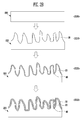
- FIG. 2A is a diagram illustrating a food container having a nano-structured hydrophobic surface according to a second exemplary embodiment of the present invention.
- a food container 200 having a nano-structured hydrophobic surface (hereinafter, referred to as a "food container") according to a second exemplary embodiment of the present invention includes a plurality of nano-structures 20, a first hydrophobic thin film 30, and a gas blocking film 40.
- the present exemplary embodiment is different from the first exemplary embodiment in that the gas blocking film 40 is further included, so that the present exemplary embodiment will be described based on the gas blocking film 40, and descriptions overlapping those of the first exemplary embodiment will be omitted.
- the gas blocking film 40 is formed between the surface of the food container 200 and the first hydrophobic thin film 30.
- first hydrophobic thin film 30 is coated on the surface of the food container 200 in which the gas blocking film 40 is formed.
- the gas blocking film 40 is inserted between the food container 200 and the first hydrophobic thin film 30, so that the food container 200 according to the exemplary embodiment of the present invention may have excellent gas blocking performance. Accordingly, food stored inside the food container 200 may be preserved for a long time.
- the gas blocking film 40 has a high thin film density, so that the gas blocking film 40 may be silicon oxide having excellent gas blocking performance.
- a sum of a thickness h3 of the first hydrophobic thin film 30 and a thickness h4 of the gas blocking film 40 is set to be excessively large, a space between the nano-structures 20 is decreased, thereby causing a problem in that hydrophobicity deteriorates, so that the sum of the thickness h3 of the first hydrophobic thin film 30 and the thickness h4 of the gas blocking film 40 may be set to be a half of a height h2 of the nano-structure 20 or smaller.
- FIG. 2B is a diagram illustrating a method of manufacturing the food container illustrated in FIG. 2A . That is, a method of manufacturing the food container 200 according to the second exemplary embodiment of the present invention includes a food container preparing step S200, a nano-structure forming step S210, a gas blocking film coating step S220, and a first hydrophobic thin film coating step S230.
- the food container preparing step S200 and the nano-structure forming step S210 are identically performed to those aforementioned the first exemplary embodiment.
- the gas blocking film coating step S220 is performed before the first hydrophobic thin film coating step S230.
- gas blocking film coating step S220 the gas blocking film 40 is coated on the surface of the food container 200 in which the nano-structures 20 are formed.
- the process may be performed within the chamber of the RF-CVD equipment using plasma.
- the gas blocking film 40 has a high thin film density, so that the gas blocking film 40 may be silicon oxide having excellent gas blocking performance.
- the first hydrophobic thin film coating step S230 of coating the first hydrophobic thin film 30 on the gas blocking film 40 is performed.
- the first hydrophobic thin film coating step S230 may be identically performed to that described in the first exemplary embodiment.
- gas blocking film coating step S220 and the first hydrophobic thin film coating step S230 may be discontinuously or continuously performed.
- the plasma state is released after the gas blocking film 40 is formed, and the plasma state is generated again after confirming that gas for coating the first hydrophobic thin film 30 stably flows into the chamber to coat the first hydrophobic thin film 30.
- the gas blocking film 40 and the first hydrophobic thin film 30 are discontinuously combined so as to prevent mutual composition from being continuously changed.
- the plasma state is continuously maintained even after the gas blocking film 40 is formed, and gas flowing into the chamber is continuously changed from gas forming the gas blocking film 40 to gas forming the first hydrophobic thin film 30.
- the continuous process may be used for reducing a time consumed for changing gas in a factory performing mass production, and has an effect in that difference in stress applied to the thin films is released during discontinuous deposition.
- the nano-structures 20, the gas blocking film 40, and the first hydrophobic thin film 30 are sequentially positioned on the surface of the food container 200 as a result.
- FIG. 3A is a diagram illustrating a food container having a nano-structured hydrophobic surface according to a third exemplary embodiment of the present invention.
- a food container 300 having a nano-structured hydrophobic surface (hereinafter, referred to as a "food container") according to a third exemplary embodiment of the present invention includes a plurality of nano-structures 20, a first hydrophobic thin film 30, a gas blocking film 40, and a second hydrophobic thin film 50.
- the present exemplary embodiment is different from the second exemplary embodiment in that the second hydrophobic thin film 50 is further included, so that the present exemplary embodiment will be described based on the second hydrophobic thin film 50, and descriptions overlapping those of the second exemplary embodiment will be omitted.
- the second hydrophobic thin film 50 is formed between a surface of the food container 300 and the gas blocking film 40. That is, the second hydrophobic thin film 50 is first coated on the surface of the food container 300, and then the gas blocking film 40 is formed on the second hydrophobic thin film 50.
- the gas blocking film 40 is coated, and then the first hydrophobic thin film 30 is coated on the gas blocking film 40.
- the second hydrophobic thin film 50, the gas blocking film 40, and the first hydrophobic thin film 30 are sequentially positioned on the nano-structures 20 of the food container 300.
- the gas blocking film 40 having flexibility is directly coated on the food container 300, there is a problem in that strong residual stress is left, and the second hydrophobic thin film 50 positioned at the lowermost side serves as a buffer thin film (buffer layer) for releasing the problem.
- the second hydrophobic thin film 50 may be formed of the same material as that of the first hydrophobic thin film 30. Accordingly, the second hydrophobic thin film 50 may also be implemented by hexamethyldisiloxane (HMDSO), but may also adopt polytetrafluoroethylene (PTFE) or alkyl keton dimer (AKD), which is a conventionally well-known hydrophobic thin film.
- HMDSO hexamethyldisiloxane
- PTFE polytetrafluoroethylene
- ALD alkyl keton dimer
- a sum of a thickness h3 of the first hydrophobic thin film 30, a thickness h4 of the gas blocking film 40, and a thickness h5 of the second hydrophobic thin film 50 is set to be excessively large, a space between the nano-structures 20 is decreased, thereby causing a problem in that hydrophobicity deteriorates, so that the sum of the thickness h3 of the first hydrophobic thin film 30, the thickness h4 of the gas blocking film 40, and a thickness h5 of the second hydrophobic thin film 50 may be set to be a half of a height h2 of the nano-structure 20 or smaller.
- FIG. 3B is a diagram illustrating a method of manufacturing the food container illustrated in FIG. 3A . That is, a method of manufacturing the food container 300 according to the third exemplary embodiment of the present invention includes a food container preparing step S300, a nano-structure forming step S310, a second hydrophobic thin film coating step S320, a gas blocking film coating step S330, and a first hydrophobic thin film coating step S340.
- the food container preparing step S300 and the nano-structure forming step S310 are identically performed to those aforementioned the first and second exemplary embodiments.
- the second hydrophobic thin film coating step S320 is performed before the gas blocking film coating step S330.
- the second hydrophobic thin film 50 is coated on the surface of the food container 300 in which the nano-structures 20 are formed, which may be performed by the same method as that of the first hydrophobic thin film coating step S120 in the aforementioned first exemplary embodiment.
- gas blocking film coating step S330 and the first hydrophobic thin film coating step S340 are sequentially performed equally to those of the second exemplary embodiment.
- the gas blocking film 40 is coated on the second hydrophobic thin film 50, and in the first hydrophobic thin film coating step S340, the first hydrophobic thin film 30 is coated on the gas blocking film 40.
- the second hydrophobic thin film coating step S320, the gas blocking film coating step S330, and the first hydrophobic thin film coating step S340 may be discontinuously performed similar to the second exemplary embodiment, or may be continuously performed.
- the plasma state is released after the second hydrophobic thin film 50 is formed, the plasma state is generated again after confirming that gas coated on the gas blocking film 40 stably flows into the chamber to form the gas blocking film 40, the plasma state is released after forming the gas blocking film 40, and the plasma state is generated again after confirming that gas coated on the first hydrophobic thin film 30 stably flows into the chamber to coat the first hydrophobic thin film 30.
- the second hydrophobic thin film 50, the gas blocking film 40, and the first hydrophobic thin film 30 are discontinuously combined so as to prevent mutual composition from being continuously changed.
- the plasma state is continuously maintained even after the second hydrophobic thin film 50 is formed, and gas flowing into the chamber is continuously changed from gas forming the second hydrophobic thin film 50 to the gas forming the gas blocking film 40. Further, the plasma state is continuously maintained even after the gas blocking film 40 is formed, and gas flowing into the chamber is continuously changed from gas forming the gas blocking film 40 to gas forming the first hydrophobic thin film 30.
- the continuous process it is possible to form a thin film structure in which composition is gradually changed from the second hydrophobic thin film 50 to the first hydrophobic thin film 30 via the gas blocking film 40. That is, as another expression, it is possible to form a thin film structure in which thin films are continuously connected.
- the continuous process may be used for reducing a time consumed for changing gas in a factory performing mass production, and has an effect in that difference in stress applied to the thin films is released during discontinuous deposition.
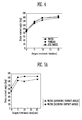
- FIG. 4 is a graph illustrating a static contact angle between water, vinegar, and soy sauce measured according to a time of oxygen plasma processing performed on the food container.
- an x-axis indicates a time of oxygen plasma processing performed before coating the hydrophobic thin film and the gas blocking film
- a y-axis indicates a static contact angle measured in a state where a corresponding liquid droplet is stopped.
- a vacuum pressure within the chamber is decreased with high vacuum of 10-6 mtorr by using a rotary pump and a turbo pump, and then plasma processing starts to be performed on the surface of the PP sheet.
- the plasma state is formed by RF-power.
- the plurality of nano-structures 20 is formed on the surface of the PP sheet by chemical reaction between the PP sheet and the oxygen plasma.
- the second hydrophobic thin film 50, the gas blocking film 40, the first hydrophobic thin film 30 are sequentially coated.
- the first hydrophobic thin film 30 and the second hydrophobic thin film 50 are formed of pp-hexamethyldisiloxane (pp-HMDSO), and the gas blocking film 40 is formed of silicon oxide.
- first hydrophobic thin film 30 and the second hydrophobic thin film 50 are coated with a thickness of 30 nm, and the gas blocking film 40 is coated with a thickness of 30 nm.
- FIG. 5A is a graph illustrating a dynamic contact angle of water according to a time of oxygen plasma processing performed on the food container
- FIG. 5B is a graph illustrating a dynamic contact angle of vinegar according to a time of oxygen plasma processing performed on the food container
- FIG. 5C is a graph illustrating a dynamic contact angle of soy sauce according to a time of oxygen plasma processing performed on the food container.
- an x-axis indicates a time of oxygen plasma processing performed before coating the hydrophobic thin film and the gas blocking film
- a y-axis indicates a dynamic contact angle.
- a fact that the contact angle hysteresis is small means that even though a surface is slightly inclined, the liquid easily flows down on the surface. That is, it means that as the contact angle hysteresis is small, the liquid is not attached to the surface.
- FIGS. 5A to 5C as a time of the oxygen plasma processing is increased, the contact angle hysteresis of water, vinegar, and soy sauce is decreased.
- Nano-structure 30 First hydrophobic thin film 40: Gas blocking film 50: Second hydrophobic thin film 60: Food 100, 200, 300: Food container
Landscapes
- Chemical & Material Sciences (AREA)
- Engineering & Computer Science (AREA)
- Mechanical Engineering (AREA)
- General Chemical & Material Sciences (AREA)
- Chemical Kinetics & Catalysis (AREA)
- Materials Engineering (AREA)
- Metallurgy (AREA)
- Organic Chemistry (AREA)
- Food Science & Technology (AREA)
- Inorganic Chemistry (AREA)
- Ceramic Engineering (AREA)
- Physics & Mathematics (AREA)
- Plasma & Fusion (AREA)
- Details Of Rigid Or Semi-Rigid Containers (AREA)
- Packging For Living Organisms, Food Or Medicinal Products That Are Sensitive To Environmental Conditiond (AREA)
- Laminated Bodies (AREA)
- Wrappers (AREA)
Abstract
Description
- The present invention relates to a food container and a manufacturing method thereof, and more particularly, to a food container having a nano-structured hydrophobic surface having hydrophobicity and a gas blocking property, and a manufacturing method thereof.
- Recently, a food container, which is used for storing food and the like, is mainly formed of a plastic material, such as polypropylene (PP) or polyethylene terephthalate (PET) by reason of manufacturing easiness and a low cost.
- A plastic material having relatively low surface energy is a hydrophilic material having a contact angle of 50 to 80° with respect to pure water.
- A fact that a surface has hydrophilicity means that the surface prefers a contact with water to a contact with air, and water attached to the surface has a wide contact area with the surface and is not well separated from the surface. That is, food is stably attached to the surface.
- In a case where an attachment degree of food is high, a stain is generated on a surface of the food container even after the food is removed, and further, there is a problem in that food residue is left on the surface of the food container by the stable contact between the surface of the food container and the food.
- An object of the present invention is to provide a food container having a nano-structured hydrophobic surface capable of preventing a stain generated due to a contact of food containing water with a surface of the food container, decreasing food residual left on the surface of the food container, and preventing a harmful influence from the food container by minimizing a contact area of food and the food container, and a manufacturing method thereof.
- In order to achieve the aforementioned object, the present invention provides a food container made of a plastic material and having a nano-structured hydrophobic surface, including: a plurality of nano-structures formed on a surface of the food container; and a first hydrophobic thin film coated on an upper side of the surface, on which the nano-structures are formed.
- Further, the food container may further include a gas blocking film formed between the surface of the food container and the first hydrophobic thin film.
- Further, the food container may further include a second hydrophobic thin film formed between the surface of the food container and the gas blocking film.
- Further, the nano-structure may have any one shape among a nano-pillar shape, a nano-rod shape, a nano-dot shape, and a nano-wire shape.
- Further, the nano-structure may have a width of 1 to 100 nm and a height of 1 to 1000 nm.
- Further, a contact angle of the first hydrophobic thin film may be equal to or larger than 90°, and contact angle hysteresis of the first hydrophobic thin film may be less than 30°.
- Further, a sum of a thickness of the first hydrophobic thin film and a thickness of the gas blocking film may be a half of a height of the nano-structure or lower.
- Further, a sum of a thickness of the first hydrophobic thin film, a thickness of the gas blocking film, and a thickness of the second hydrophobic thin film may be a half of a height of the nano-structure or lower.
- Further, the first hydrophobic thin film is formed of hexamethyldisiloxane
- Further, the gas blocking film may be formed of silicon oxide.
- Further, the second hydrophobic thin film may be formed of hexamethyldisiloxane
- Further, the gas blocking film and the first and second hydrophobic thin films may be discontinuously combined.
- Further, the gas blocking film and the first and second hydrophobic thin films may be continuously combined according to a continuous change in mutual chemical composition.
- A method of manufacturing a food container having a nano-structured hydrophobic surface of the present invention includes: forming a plurality of nano-structures on a surface of the food container formed of a plastic material; and coating a first hydrophobic thin film on an upper side of the surface, on which the nano-structures are formed.
- Further, the method may further include coating a gas blocking film on the upper side of the surface, on which the nano-structures are formed, between the forming of the plurality of nano-structures and the coating of the first hydrophobic thin film.
- Further, the method may further include coating a second hydrophobic thin film on the upper side of the surface, on which the nano-structures are formed, between the forming of the plurality of nano-structures and the coating of the gas blocking film.
- Further, the nano-structure may have any one shape among a nano-pillar shape, a nano-rod shape, a nano-dot shape, and a nano-wire shape.
- Further, the nano-structure may have a width of 1 to 100 nm and a height of 1 to 1000 nm.
- Further, a contact angle of the first hydrophobic thin film may be equal to or larger than 90°, and contact angle hysteresis of the first hydrophobic thin film may be less than 30°.
- Further, a sum of a thickness of the first hydrophobic thin film and a thickness of the gas blocking film may be a half of a height of the nano-structure or lower.
- Further, a sum of a thickness of the first hydrophobic thin film, a thickness of the gas blocking film, and a thickness of the second hydrophobic thin film may be a half of a height of the nano-structure or lower.
- Further, the first hydrophobic thin film may be formed of hexamethyldisiloxane Further, the gas blocking film may be formed of silicon oxide.
- Further, the second hydrophobic thin film may be formed of hexamethyldisiloxane
- Further, the gas blocking film and the first and second hydrophobic thin films may be discontinuously combined.
- Further, the gas blocking film and the first and second hydrophobic thin films may be continuously combined according to a continuous change in mutual chemical composition.
- As described above, according to the present invention, it is possible to provide the food container having the nano-structured hydrophobic surface capable of preventing a stain generated due to a contact of food containing water with a surface of the food container, decreasing food residual left on the surface of the food container, and preventing a harmful influence from the food container by minimizing a contact area of food and the food container, and a manufacturing method thereof.
- Further, according to the present invention, it is possible to provide the food container having the nano-structured hydrophobic surface capable of having excellent gas blocking performance, as well as hydrophobicity, by additionally forming the gas blocking film, and the manufacturing method thereof.
-
-
FIG. 1A is a diagram illustrating a food container having a nano-structured hydrophobic surface according to a first exemplary embodiment of the present invention. -
FIG. 1B is a diagram illustrating a method of manufacturing the food container illustrated inFIG. 1A . -
FIG. 2A is a diagram illustrating a food container having a nano-structured hydrophobic surface according to a second exemplary embodiment of the present invention. -
FIG. 2B is a diagram illustrating a method of manufacturing the food container illustrated inFIG. 2A . -
FIG. 3A is a diagram illustrating a food container having a nano-structured hydrophobic surface according to a third exemplary embodiment of the present invention. -
FIG. 3B is a diagram illustrating a method of manufacturing the food container illustrated inFIG. 3A . -
FIG. 4 is a graph illustrating a static contact angle between water, vinegar, and soy sauce measured according to a time of oxygen plasma processing performed on the food container. -
FIG. 5A is a graph illustrating a dynamic contact angle of water according to a time of oxygen plasma processing performed on the food container. -
FIG. 5B is a graph illustrating a dynamic contact angle of vinegar according to a time of oxygen plasma processing performed on the food container. -
FIG. 5C is a graph illustrating a dynamic contact angle of soy sauce according to a time of oxygen plasma processing performed on the food container. - Other detailed matters of the exemplary embodiments are included in the detailed description and the drawings.
- Various advantages and features of the present disclosure and methods accomplishing thereof will become apparent from the following detailed description of exemplary embodiments with reference to the accompanying drawings. However, the present invention is not limited to the exemplary embodiments set forth below, and may be embodied in various other forms. The present exemplary embodiments are for rendering the description of the present invention complete and are set forth to provide a complete understanding of the scope of the invention to a person with ordinary skill in the technical field to which the present invention pertains, and the present invention will only be defined by the scope of the claims. Like reference numerals indicate like elements throughout the specification.
- Hereinafter, a food container having a nano-structured hydrophobic surface and a method of manufacturing the same according to the present invention will be described with reference to the exemplary embodiment of the present invention and the drawings for describing the exemplary embodiment of the present invention.
-
FIG. 1A is a diagram illustrating a food container having a nano-structured hydrophobic surface according to a first exemplary embodiment of the present invention. - Referring to
FIG. 1A , afood container 100 having a nano-structured hydrophobic surface (hereinafter, referred to as a "food container") according to a first exemplary embodiment of the present invention includes a plurality of nano-structures 20 and a first hydrophobicthin film 30. - The
food container 100 is formed of a plastic material, such as polypropylene (PP), polyethylene terephthalate (PET), polyethylene (PE), polystyrene (PS) and the like. - In order to solve a problem (the
food container 100 has hydrophilicity, so that food is attached to the food container 100) of thefood container 100 formed of the plastic material, thefood container 100 according to the exemplary embodiment is formed of the plurality of nano-structures 20 on a surface thereof. - That is, an air membrane is stably positioned in a space between the
respective nano structures 20, so that the surface of thefood container 100 has a very small contact area withfood 60 containing water. Accordingly, the surface of thefood container 100 has the hydrophobicity. - Further, in order to improve the hydrophobicity of the surface of the
food container 100, a first hydrophobicthin film 30 may be coated on an upper side of the surface of thefood container 100, on which the nano-structures are formed. - The first hydrophobic
thin film 30 may be implemented by a material, which has low surface energy to have hydrophobicity, and may be preferably implemented by hexamethyldisiloxane (HMDSO), but may also adopt polytetrafluoroethylene (PTFE) or alkyl keton dimer (AKD), which is a conventionally well-known hydrophobic thin film. - Further, in the
food container 100 in the present exemplary embodiment, a contact angle of a water drop, which is in contact with the first hydrophobicthin film 30, is 90° or more through the forming of the nano-structures 20 and the first hydrophobicthin film 30, and contact angle hysteresis is also less than 30°. - A contact angle is defined as an angle between a liquid surface and a solid surface in a liquid and a solid which are in contact with each other, and is generally represented by an angle formed between a tangent line from a contact point of a droplet and a solid leaded to a droplet surface and the solid surface. The contact angle is used as a criterion indicating wettability of the solid surface.
- That is, as a contact angle is small, hydrophilicity is large, and as a contact angle is large, hydrophobicity is large.
- Contact angle hysteresis may be defined by a difference between an advancing contact angle, at which a liquid starts to move forward from the surface, and a receding contact angle, at which the liquid starts to move backward from the surface, and the fact that a value of the contact angle hysteresis is large means that a liquid is not well detached from a surface, and the fact that a value of the contact angle hysteresis is small means that a liquid is well detached from a surface.
- Accordingly, as described above, the contact angle of the first hydrophobic
thin film 30 may be formed to be 90° or greater to achieve hydrophobicity, and the contact angle hysteresis may be formed to be less than 30°, thereby making thefood 60 be well detached from the surface of thefood container 100. - Here, the shape of the nano-
structure 20 may be variously implemented, and an example thereof may include any one of a nanopillar shape, a nanorod shape, a nanodot shape, and a nanowire shape. - Further, a width of the nano-
structure 20 may be set to be 1 to 100 nm, and a height thereof may be set to be 1 to 1000 nm. -
FIG. 1B is a diagram illustrating a method of manufacturing the food container illustrated inFIG. 1A . That is, a method of manufacturing thefood container 100 according to the first exemplary embodiment of the present invention includes a food container preparing step S100, a nano-structure forming step S110, and a first hydrophobic thin film coating step S120. - First, in the food container preparing step S100, the
food container 100, which is formed of a plastic material and has a flat surface, is prepared. - Then, the nano-structure forming step S110 of forming the plurality of nano-
structures 20 on the surface of thefood container 100 is performed. - In the nano-structure forming step S110, dust on the surface of the
food container 100 is removed by using a nitrogen gun (not shown). Then, thefood container 100 is positioned within a chamber of Radio Frequency-Chemical Vapor Deposition (RF-CVD) equipment (not shown), and a vacuum state is formed. - A vacuum pressure within the chamber of the RF-CVD equipment is adjusted to a predetermined value by using a pump and the like, and plasma processing starts on the surface of the
food container 100. - To this end, after oxygen gas is inserted into the chamber, a plasma state is generated by RF-power. Then, the plurality of nano-
structures 20 is formed on the surface of thefood container 100 by a chemical reaction between thefood container 100 and oxygen plasma. - As the time of the oxygen plasma processing on the
food container 100 is increased, a height of the nano-structure 20 is increased, and a width thereof is decreased. That is, the sharper and longer nano-structure is formed. - Next, the first hydrophobic thin film
coating step S 120 is performed. - In the first hydrophobic thin film coating step S120, after the oxygen plasma processing performed in the nano-structure forming step S110 is completed, a first hydrophobic thin film forming material in a gas state is inserted into the chamber of the RF-CVD equipment. Then, the plasma state is generated by the RF-power again, so that the first hydrophobic thin film forming material in the gas state may be deposited on the surface of the
food container 100 in which the nano-structures 20 are formed. Accordingly, the first hydrophobicthin film 30 is finally coated on the surface of thefood container 100. - For example, when hexamethyldisiloxane (HMDSO) gas is inserted as the first hydrophobic thin film forming material, the first hydrophobic
thin film 30 made of plasma polymerized HMDSO (pp-HMDSO) may be formed. The first hydrophobicthin film 30 made of plasma polymerized HMDSO (pp-HMDSO) has low surface energy to have hydrophobicity. - It is possible to manufacture the food container having hydrophobicity through the aforementioned manufacturing method, and thus it is possible to prevent a phenomenon in that liquid-state food is attached to the surface of the food container, thereby preventing a phenomenon in that a stain is generated on the surface of the food container and minimizing the amount of food left on the surface of the food container.
- Further, it is possible to minimize a contact area between the food and the food container, thereby preventing harmful ingredients from being transferred from the food container to the food.
-
FIG. 2A is a diagram illustrating a food container having a nano-structured hydrophobic surface according to a second exemplary embodiment of the present invention. - Referring to
FIG. 2A , afood container 200 having a nano-structured hydrophobic surface (hereinafter, referred to as a "food container") according to a second exemplary embodiment of the present invention includes a plurality of nano-structures 20, a first hydrophobicthin film 30, and agas blocking film 40. - That is, the present exemplary embodiment is different from the first exemplary embodiment in that the
gas blocking film 40 is further included, so that the present exemplary embodiment will be described based on thegas blocking film 40, and descriptions overlapping those of the first exemplary embodiment will be omitted. - The
gas blocking film 40 is formed between the surface of thefood container 200 and the first hydrophobicthin film 30. - Further, the first hydrophobic
thin film 30 is coated on the surface of thefood container 200 in which thegas blocking film 40 is formed. - The
gas blocking film 40 is inserted between thefood container 200 and the first hydrophobicthin film 30, so that thefood container 200 according to the exemplary embodiment of the present invention may have excellent gas blocking performance. Accordingly, food stored inside thefood container 200 may be preserved for a long time. - In this case, the
gas blocking film 40 has a high thin film density, so that thegas blocking film 40 may be silicon oxide having excellent gas blocking performance. - Further, in a case where a sum of a thickness h3 of the first hydrophobic
thin film 30 and a thickness h4 of thegas blocking film 40 is set to be excessively large, a space between the nano-structures 20 is decreased, thereby causing a problem in that hydrophobicity deteriorates, so that the sum of the thickness h3 of the first hydrophobicthin film 30 and the thickness h4 of thegas blocking film 40 may be set to be a half of a height h2 of the nano-structure 20 or smaller. -
FIG. 2B is a diagram illustrating a method of manufacturing the food container illustrated inFIG. 2A . That is, a method of manufacturing thefood container 200 according to the second exemplary embodiment of the present invention includes a food container preparing step S200, a nano-structure forming step S210, a gas blocking film coating step S220, and a first hydrophobic thin film coating step S230. - The food container preparing step S200 and the nano-structure forming step S210 are identically performed to those aforementioned the first exemplary embodiment.
- Next, differently from the first exemplary embodiment, in the present exemplary embodiment, the gas blocking film coating step S220 is performed before the first hydrophobic thin film coating step S230.
- In gas blocking film coating step S220, the
gas blocking film 40 is coated on the surface of thefood container 200 in which the nano-structures 20 are formed. - The process may be performed within the chamber of the RF-CVD equipment using plasma.
- For example, the
gas blocking film 40 has a high thin film density, so that thegas blocking film 40 may be silicon oxide having excellent gas blocking performance. - Then, the first hydrophobic thin film coating step S230 of coating the first hydrophobic
thin film 30 on thegas blocking film 40 is performed. - The first hydrophobic thin film coating step S230 may be identically performed to that described in the first exemplary embodiment.
- Here, the gas blocking film coating step S220 and the first hydrophobic thin film coating step S230 may be discontinuously or continuously performed.
- According to the discontinuous process, the plasma state is released after the
gas blocking film 40 is formed, and the plasma state is generated again after confirming that gas for coating the first hydrophobicthin film 30 stably flows into the chamber to coat the first hydrophobicthin film 30. - Accordingly, the
gas blocking film 40 and the first hydrophobicthin film 30 are discontinuously combined so as to prevent mutual composition from being continuously changed. - In the meantime, according to the continuous process, the plasma state is continuously maintained even after the
gas blocking film 40 is formed, and gas flowing into the chamber is continuously changed from gas forming thegas blocking film 40 to gas forming the first hydrophobicthin film 30. - According to the continuous process, it is possible to form a thin film structure in which composition is gradually changed from the
gas blocking film 40 to the first hydrophobicthin film 30. That is, as another expression, it is possible to form a thin film structure in which thin films are continuously connected. - The continuous process may be used for reducing a time consumed for changing gas in a factory performing mass production, and has an effect in that difference in stress applied to the thin films is released during discontinuous deposition.
- According to the aforementioned process, the nano-
structures 20, thegas blocking film 40, and the first hydrophobicthin film 30 are sequentially positioned on the surface of thefood container 200 as a result. -
FIG. 3A is a diagram illustrating a food container having a nano-structured hydrophobic surface according to a third exemplary embodiment of the present invention. - Referring to
FIG. 3A , afood container 300 having a nano-structured hydrophobic surface (hereinafter, referred to as a "food container") according to a third exemplary embodiment of the present invention includes a plurality of nano-structures 20, a first hydrophobicthin film 30, agas blocking film 40, and a second hydrophobicthin film 50. - That is, the present exemplary embodiment is different from the second exemplary embodiment in that the second hydrophobic
thin film 50 is further included, so that the present exemplary embodiment will be described based on the second hydrophobicthin film 50, and descriptions overlapping those of the second exemplary embodiment will be omitted. - The second hydrophobic
thin film 50 is formed between a surface of thefood container 300 and thegas blocking film 40. That is, the second hydrophobicthin film 50 is first coated on the surface of thefood container 300, and then thegas blocking film 40 is formed on the second hydrophobicthin film 50. - Further, after the
gas blocking film 40 is coated, and then the first hydrophobicthin film 30 is coated on thegas blocking film 40. - Accordingly, the second hydrophobic
thin film 50, thegas blocking film 40, and the first hydrophobicthin film 30 are sequentially positioned on the nano-structures 20 of thefood container 300. - When the
gas blocking film 40 having flexibility is directly coated on thefood container 300, there is a problem in that strong residual stress is left, and the second hydrophobicthin film 50 positioned at the lowermost side serves as a buffer thin film (buffer layer) for releasing the problem. - The second hydrophobic
thin film 50 may be formed of the same material as that of the first hydrophobicthin film 30. Accordingly, the second hydrophobicthin film 50 may also be implemented by hexamethyldisiloxane (HMDSO), but may also adopt polytetrafluoroethylene (PTFE) or alkyl keton dimer (AKD), which is a conventionally well-known hydrophobic thin film. - Further, in a case where a sum of a thickness h3 of the first hydrophobic
thin film 30, a thickness h4 of thegas blocking film 40, and a thickness h5 of the second hydrophobicthin film 50 is set to be excessively large, a space between the nano-structures 20 is decreased, thereby causing a problem in that hydrophobicity deteriorates, so that the sum of the thickness h3 of the first hydrophobicthin film 30, the thickness h4 of thegas blocking film 40, and a thickness h5 of the second hydrophobicthin film 50 may be set to be a half of a height h2 of the nano-structure 20 or smaller. -
FIG. 3B is a diagram illustrating a method of manufacturing the food container illustrated inFIG. 3A . That is, a method of manufacturing thefood container 300 according to the third exemplary embodiment of the present invention includes a food container preparing step S300, a nano-structure forming step S310, a second hydrophobic thin film coating step S320, a gas blocking film coating step S330, and a first hydrophobic thin film coating step S340. - The food container preparing step S300 and the nano-structure forming step S310 are identically performed to those aforementioned the first and second exemplary embodiments.
- Next, differently from the second exemplary embodiment, in the present exemplary embodiment, the second hydrophobic thin film coating step S320 is performed before the gas blocking film coating step S330.
- In the second hydrophobic thin film coating step S320, the second hydrophobic
thin film 50 is coated on the surface of thefood container 300 in which the nano-structures 20 are formed, which may be performed by the same method as that of the first hydrophobic thin film coating step S120 in the aforementioned first exemplary embodiment. - Then, the gas blocking film coating step S330 and the first hydrophobic thin film coating step S340 are sequentially performed equally to those of the second exemplary embodiment.
- In the gas blocking film coating step S330, the
gas blocking film 40 is coated on the second hydrophobicthin film 50, and in the first hydrophobic thin film coating step S340, the first hydrophobicthin film 30 is coated on thegas blocking film 40. - Here, the second hydrophobic thin film coating step S320, the gas blocking film coating step S330, and the first hydrophobic thin film coating step S340 may be discontinuously performed similar to the second exemplary embodiment, or may be continuously performed.
- According to the discontinuous process, the plasma state is released after the second hydrophobic
thin film 50 is formed, the plasma state is generated again after confirming that gas coated on thegas blocking film 40 stably flows into the chamber to form thegas blocking film 40, the plasma state is released after forming thegas blocking film 40, and the plasma state is generated again after confirming that gas coated on the first hydrophobicthin film 30 stably flows into the chamber to coat the first hydrophobicthin film 30. - Accordingly, the second hydrophobic
thin film 50, thegas blocking film 40, and the first hydrophobicthin film 30 are discontinuously combined so as to prevent mutual composition from being continuously changed. - In the meantime, according to the continuous process, the plasma state is continuously maintained even after the second hydrophobic
thin film 50 is formed, and gas flowing into the chamber is continuously changed from gas forming the second hydrophobicthin film 50 to the gas forming thegas blocking film 40. Further, the plasma state is continuously maintained even after thegas blocking film 40 is formed, and gas flowing into the chamber is continuously changed from gas forming thegas blocking film 40 to gas forming the first hydrophobicthin film 30. - According to the continuous process, it is possible to form a thin film structure in which composition is gradually changed from the second hydrophobic
thin film 50 to the first hydrophobicthin film 30 via thegas blocking film 40. That is, as another expression, it is possible to form a thin film structure in which thin films are continuously connected. - The continuous process may be used for reducing a time consumed for changing gas in a factory performing mass production, and has an effect in that difference in stress applied to the thin films is released during discontinuous deposition.
-
FIG. 4 is a graph illustrating a static contact angle between water, vinegar, and soy sauce measured according to a time of oxygen plasma processing performed on the food container. In this case, an x-axis indicates a time of oxygen plasma processing performed before coating the hydrophobic thin film and the gas blocking film, and a y-axis indicates a static contact angle measured in a state where a corresponding liquid droplet is stopped. - An experiment is performed by using a polypropylene (PP) sheet, which is a plastic material widely used as the food container.
- In order to form the nano-structures on a surface of the PP sheet, dust on the surface of the PP sheet is first clearly blown by using a nitrogen gun for one minute, and then the PP sheet is positioned within the chamber of the Radio Frequency-Chemical Vapor Deposition (RF-CVD) equipment (not shown), and a vacuum state is formed.
- A vacuum pressure within the chamber is decreased with high vacuum of 10-6 mtorr by using a rotary pump and a turbo pump, and then plasma processing starts to be performed on the surface of the PP sheet. To this end, after inserting oxygen gas into the chamber, the plasma state is formed by RF-power. Then, the plurality of nano-
structures 20 is formed on the surface of the PP sheet by chemical reaction between the PP sheet and the oxygen plasma. - Then, the second hydrophobic
thin film 50, thegas blocking film 40, the first hydrophobicthin film 30 are sequentially coated. In this case, the first hydrophobicthin film 30 and the second hydrophobicthin film 50 are formed of pp-hexamethyldisiloxane (pp-HMDSO), and thegas blocking film 40 is formed of silicon oxide. - Further, the first hydrophobic
thin film 30 and the second hydrophobicthin film 50 are coated with a thickness of 30 nm, and thegas blocking film 40 is coated with a thickness of 30 nm. - As can be seen in the graph illustrated in
FIG. 4 , as the time of the oxygen plasma processing is increased, the contact angle is increased. That is, it can be seen that hydrophobicity of the surface of the PP sheet is improved. -
FIG. 5A is a graph illustrating a dynamic contact angle of water according to a time of oxygen plasma processing performed on the food container,FIG. 5B is a graph illustrating a dynamic contact angle of vinegar according to a time of oxygen plasma processing performed on the food container, andFIG. 5C is a graph illustrating a dynamic contact angle of soy sauce according to a time of oxygen plasma processing performed on the food container. In this case, an x-axis indicates a time of oxygen plasma processing performed before coating the hydrophobic thin film and the gas blocking film, and a y-axis indicates a dynamic contact angle. - Particularly, in order to recognize the contact angle hysteresis, an advancing contact angle and a receding contact angle of a corresponding liquid droplet are separately illustrated.
- A fact that the contact angle hysteresis is small means that even though a surface is slightly inclined, the liquid easily flows down on the surface. That is, it means that as the contact angle hysteresis is small, the liquid is not attached to the surface. As can be seen in
FIGS. 5A to 5C , as a time of the oxygen plasma processing is increased, the contact angle hysteresis of water, vinegar, and soy sauce is decreased. - It will be appreciated by those skilled in the art that the present invention described above may be implemented into other specific forms without departing from the technical spirit thereof or essential characteristics. Thus, it is to be appreciated that exemplary embodiments described above are intended to be illustrative in every sense, and not restrictive. The scope of the present invention is represented by the claims to be described below rather than the detailed description, and it is to be interpreted that the meaning and scope of the claims and all the changes or modified forms derived from the equivalents thereof come within the scope of the present invention.
-
20: Nano-structure 30: First hydrophobic thin film 40: Gas blocking film 50: Second hydrophobic thin film 60: Food 100, 200, 300: Food container
Claims (26)
- A food container made of a plastic material and having a nano-structured hydrophobic surface, comprising:a plurality of nano-structures formed on a surface of the food container; anda first hydrophobic thin film coated on an upper side of the surface, on which the nano-structures are formed.
- The food container of claim 1, further comprising:a gas blocking film formed between the surface of the food container and the first hydrophobic thin film.
- The food container of claim 2, further comprising:a second hydrophobic thin film formed between the surface of the food container and the gas blocking film.
- The food container of claim 1, wherein the nano-structure has any one shape among a nano-pillar shape, a nano-rod shape, a nano-dot shape, and a nano-wire shape.
- The food container of claim 1, wherein the nano-structure has a width of 1 to 100 nm and a height of 1 to 1000 nm.
- The food container of claim 1, wherein a contact angle of the first hydrophobic thin film is equal to or larger than 90°, and contact angle hysteresis of the first hydrophobic thin film is less than 30°.
- The food container of claim 2, wherein a sum of a thickness of the first hydrophobic thin film and a thickness of the gas blocking film is a half of a height of the nano-structure or lower.
- The food container of claim 3, wherein a sum of a thickness of the first hydrophobic thin film, a thickness of the gas blocking film, and a thickness of the second hydrophobic thin film is a half of a height of the nano-structure or lower.
- The food container of claim 1, wherein the first hydrophobic thin film is formed of hexamethyldisiloxane
- The food container of claim 2, wherein the gas blocking film is formed of silicon oxide.
- The food container of claim 3, wherein the second hydrophobic thin film is formed of hexamethyldisiloxane
- The food container of claim 3, wherein the gas blocking film and the first and second hydrophobic thin films are discontinuously combined.
- The food container of claim 3, wherein the gas blocking film and the first and second hydrophobic thin films are continuously combined according to a continuous change in mutual chemical composition.
- A method of manufacturing a food container having a nano-structured hydrophobic surface, comprising:forming a plurality of nano-structures on a surface of the food container formed of a plastic material; andcoating a first hydrophobic thin film on an upper side of the surface, on which the nano-structures are formed.
- The method of claim 14, further comprising:coating a gas blocking film on the upper side of the surface, on which the nano-structures are formed, between the forming of the plurality of nano-structures and the coating of the first hydrophobic thin film.
- The method of claim 15, further comprising:coating a second hydrophobic thin film on the upper side of the surface, on which the nano-structures are formed, between the forming of the plurality of nano-structures and the coating of the gas blocking film.
- The method of claim 14, wherein the nano-structure has any one shape among a nano-pillar shape, a nano-rod shape, a nano-dot shape, and a nano-wire shape.
- The method of claim 14, wherein the nano-structure has a width of 1 to 100 nm and a height of 1 to 1000 nm.
- The method of claim 14, wherein a contact angle of the first hydrophobic thin film is equal to or larger than 90°, and contact angle hysteresis of the first hydrophobic thin film is less than 30°.
- The method of claim 15, wherein a sum of a thickness of the first hydrophobic thin film and a thickness of the gas blocking film is a half of a height of the nano-structure or lower.
- The method of claim 16, wherein a sum of a thickness of the first hydrophobic thin film, a thickness of the gas blocking film, and a thickness of the second hydrophobic thin film is a half of a height of the nano-structure or lower.
- The method of claim 14, wherein the first hydrophobic thin film is formed of hexamethyldisiloxane
- The method of claim 15, wherein the gas blocking film is formed of silicon oxide.
- The method of claim 16, wherein the second hydrophobic thin film is formed of hexamethyldisiloxane
- The method of claim 16, wherein the gas blocking film and the first and second hydrophobic thin films are discontinuously combined.
- The method of claim 16, wherein the gas blocking film and the first and second hydrophobic thin films are continuously combined according to a continuous change in mutual chemical composition.
Applications Claiming Priority (2)
| Application Number | Priority Date | Filing Date | Title |
|---|---|---|---|
| KR1020110091338A KR20130027852A (en) | 2011-09-08 | 2011-09-08 | Food container having hydrophobic surface consisting of nanostructure and the manufacturing method thereof |
| PCT/KR2012/007177 WO2013036042A1 (en) | 2011-09-08 | 2012-09-06 | Food container having nanostructured hydrophobic surface and manufacturing method thereof |
Publications (2)
| Publication Number | Publication Date |
|---|---|
| EP2754618A1 true EP2754618A1 (en) | 2014-07-16 |
| EP2754618A4 EP2754618A4 (en) | 2015-04-22 |
Family
ID=47832404
Family Applications (1)
| Application Number | Title | Priority Date | Filing Date |
|---|---|---|---|
| EP12829733.0A Withdrawn EP2754618A4 (en) | 2011-09-08 | 2012-09-06 | FOOD CONTAINER HAVING NANOSTRUCTURED HYDROPHOBIC SURFACE AND METHOD FOR MANUFACTURING THE SAME |
Country Status (6)
| Country | Link |
|---|---|
| US (2) | US20140246429A1 (en) |
| EP (1) | EP2754618A4 (en) |
| JP (1) | JP6085302B2 (en) |
| KR (1) | KR20130027852A (en) |
| CN (1) | CN103826978A (en) |
| WO (1) | WO2013036042A1 (en) |
Families Citing this family (8)
| Publication number | Priority date | Publication date | Assignee | Title |
|---|---|---|---|---|
| KR101821324B1 (en) * | 2012-07-13 | 2018-03-08 | 도요세이칸 그룹 홀딩스 가부시키가이샤 | Packaging container with excellent content slipperiness |
| WO2015042118A1 (en) * | 2013-09-17 | 2015-03-26 | LiquiGlide Inc. | Articles and methods for forming liquid films on surfaces of articles |
| CN108883596B (en) * | 2016-03-14 | 2021-06-18 | 电化株式会社 | Liquid repellent resin sheet and articles using the liquid repellent resin sheet |
| US10524598B2 (en) | 2016-05-03 | 2020-01-07 | Benny Green | Easily cleanable drinking assembly |
| CN105966017A (en) * | 2016-06-08 | 2016-09-28 | 竹菱(大连)实业有限公司 | Nanometer non-sticky film |
| CN106752214B (en) * | 2017-01-13 | 2020-01-31 | 吉林大学 | bionic anti-icing surface based on improvement of non-continuous wettability |
| CA3074724A1 (en) * | 2017-09-27 | 2019-04-04 | Kimberly-Clark Worldwide, Inc. | Dispenser |
| KR20240133142A (en) | 2023-02-27 | 2024-09-04 | 이현서 | Food container with a nano-coated surface |
Family Cites Families (22)
| Publication number | Priority date | Publication date | Assignee | Title |
|---|---|---|---|---|
| SE469080B (en) * | 1991-10-28 | 1993-05-10 | Eka Nobel Ab | PACKAGING MATERIAL, PROCEDURE FOR PREPARATION OF PACKAGING MATERIAL, APPLICATION OF HYDROPHOBIC ZEOLITE FOR PREPARATION OF PACKAGING MATERIAL AND USE OF PACKAGING MATERIAL |
| DE4438359C2 (en) * | 1994-10-27 | 2001-10-04 | Schott Glas | Plastic container with a barrier coating |
| SE520491C2 (en) * | 1999-04-07 | 2003-07-15 | Tetra Laval Holdings & Finance | Packaging laminate with barrier properties against gas and flavorings |
| JP3678361B2 (en) * | 2001-06-08 | 2005-08-03 | 大日本印刷株式会社 | Gas barrier film |
| JP2003095273A (en) * | 2001-09-18 | 2003-04-03 | Dainippon Printing Co Ltd | Plastic container |
| JP4467868B2 (en) * | 2002-06-19 | 2010-05-26 | 大日本印刷株式会社 | High water-repellent laminate |
| EP1388594B1 (en) * | 2002-08-07 | 2010-01-06 | Schott Ag | Composite material with smooth barrier layer and process for its production |
| CN1550326B (en) * | 2003-05-06 | 2010-08-25 | 三菱瓦斯化学株式会社 | multilayer container |
| JP4424033B2 (en) * | 2003-08-08 | 2010-03-03 | 東洋製罐株式会社 | Deposition film by plasma CVD method |
| US7258731B2 (en) * | 2004-07-27 | 2007-08-21 | Ut Battelle, Llc | Composite, nanostructured, super-hydrophobic material |
| US7150904B2 (en) * | 2004-07-27 | 2006-12-19 | Ut-Battelle, Llc | Composite, ordered material having sharp surface features |
| JP2006082814A (en) * | 2004-09-14 | 2006-03-30 | Dainippon Printing Co Ltd | Gas barrier plastic container |
| CN1693153B (en) * | 2005-05-25 | 2010-04-21 | 四川大学 | Multi-layer polymer composite packaging container with nano-layer texture and processing method thereof |
| JP2007223098A (en) * | 2006-02-22 | 2007-09-06 | Toppan Printing Co Ltd | Plastic container |
| US20090011222A1 (en) * | 2006-03-27 | 2009-01-08 | Georgia Tech Research Corporation | Superhydrophobic surface and method for forming same |
| DE102006056578A1 (en) * | 2006-11-30 | 2008-06-05 | Fraunhofer-Gesellschaft zur Förderung der angewandten Forschung e.V. | Process for producing a nanostructure on a plastic surface |
| JP5256765B2 (en) * | 2008-02-13 | 2013-08-07 | 凸版印刷株式会社 | Thin film coated plastic container |
| CN102056739B (en) * | 2008-06-12 | 2013-07-31 | Dic株式会社 | Structures coated with ultrahydrophobic nanostructure composite and processes for producing the same |
| US8734929B2 (en) * | 2008-08-25 | 2014-05-27 | Snu R&Db Foundation | Hydrophobic composites and methods of making the same |
| US9435916B2 (en) * | 2008-12-30 | 2016-09-06 | 3M Innovative Properties Company | Antireflective articles and methods of making the same |
| CN101554991B (en) * | 2009-05-11 | 2012-01-18 | 北京大学 | Processing method of diverse nano structure |
| EP2566681B1 (en) * | 2010-05-03 | 2018-09-26 | 3M Innovative Properties Company | Method of making a nanostructure |
-
2011
- 2011-09-08 KR KR1020110091338A patent/KR20130027852A/en not_active Ceased
-
2012
- 2012-09-06 JP JP2014529614A patent/JP6085302B2/en active Active
- 2012-09-06 WO PCT/KR2012/007177 patent/WO2013036042A1/en not_active Ceased
- 2012-09-06 US US14/343,574 patent/US20140246429A1/en not_active Abandoned
- 2012-09-06 EP EP12829733.0A patent/EP2754618A4/en not_active Withdrawn
- 2012-09-06 CN CN201280043931.9A patent/CN103826978A/en active Pending
-
2016
- 2016-12-20 US US15/384,995 patent/US20170101220A1/en not_active Abandoned
Also Published As
| Publication number | Publication date |
|---|---|
| CN103826978A (en) | 2014-05-28 |
| WO2013036042A1 (en) | 2013-03-14 |
| KR20130027852A (en) | 2013-03-18 |
| JP2014532012A (en) | 2014-12-04 |
| EP2754618A4 (en) | 2015-04-22 |
| JP6085302B2 (en) | 2017-02-22 |
| US20140246429A1 (en) | 2014-09-04 |
| US20170101220A1 (en) | 2017-04-13 |
Similar Documents
| Publication | Publication Date | Title |
|---|---|---|
| US20170101220A1 (en) | Food container having nanostructured hydrophobic surface and manufacturing method thereof | |
| KR101149435B1 (en) | Superhydrophobic surface material with micro and nano hybrid porous structure and a fabrication method thereof | |
| US8945409B2 (en) | Porous medium with increased hydrophobicity and method of manufacturing the same | |
| US9742038B2 (en) | Method for manufacturing all solid electrode having solid electrolyte concentration gradient | |
| JP5362941B2 (en) | Composite materials with improved chemical resistance | |
| JP6477462B2 (en) | Laminate and gas barrier film | |
| US20150191868A1 (en) | Super-hydrophobic fiber having needle-shaped nano structure on its surface, method for fabricating the same and fiber product comprising the same | |
| MX2014009161A (en) | Vapour deposition foam. | |
| US20150246477A1 (en) | Featured surface and method of making featured surface | |
| ITMI20101529A1 (en) | PLASTIC OPTICAL ELEMENTS WITH ANTI-FOLDING CHARACTERISTICS AND METHOD FOR THEIR REALIZATION | |
| KR20250022959A (en) | Polydopamine composite material and manufacturing method thereof | |
| JP5037505B2 (en) | Low wetting hysteresis polysiloxane-based material and deposition method thereof | |
| KR101350668B1 (en) | Food container having hydrophobic surface consisting of nanostructure and the manufacturing method thereof | |
| KR101734461B1 (en) | Disposable absorbent article and manufacturing method thereof | |
| JP4403093B2 (en) | Composite material and method of manufacturing the same | |
| JP4593213B2 (en) | Gas barrier plastic container and manufacturing method thereof | |
| JP4513332B2 (en) | Deposition equipment | |
| US20140332437A1 (en) | Food container having improved oxygen barrier properties and manufacturing methed thereof | |
| JP4867906B2 (en) | Transparent barrier film | |
| JP6660647B1 (en) | Resin packaging container having composite silicon oxide film or composite metal oxide film, and method for producing the same | |
| JP4333382B2 (en) | Gas barrier plastic container | |
| JP2004168325A (en) | Barrier plastic container | |
| CN112391603B (en) | System and method for preparing hollow electrode side wall insulating layer based on vapor deposition method | |
| JP2019177496A (en) | Gas barrier molded body | |
| JP2006082814A (en) | Gas barrier plastic container |
Legal Events
| Date | Code | Title | Description |
|---|---|---|---|
| PUAI | Public reference made under article 153(3) epc to a published international application that has entered the european phase |
Free format text: ORIGINAL CODE: 0009012 |
|
| 17P | Request for examination filed |
Effective date: 20140307 |
|
| AK | Designated contracting states |
Kind code of ref document: A1 Designated state(s): AL AT BE BG CH CY CZ DE DK EE ES FI FR GB GR HR HU IE IS IT LI LT LU LV MC MK MT NL NO PL PT RO RS SE SI SK SM TR |
|
| DAX | Request for extension of the european patent (deleted) | ||
| RA4 | Supplementary search report drawn up and despatched (corrected) |
Effective date: 20150325 |
|
| RIC1 | Information provided on ipc code assigned before grant |
Ipc: B65D 81/24 20060101ALI20150319BHEP Ipc: A47G 19/02 20060101ALI20150319BHEP Ipc: B65D 25/14 20060101AFI20150319BHEP Ipc: B32B 27/06 20060101ALI20150319BHEP Ipc: B65D 65/40 20060101ALI20150319BHEP |
|
| 17Q | First examination report despatched |
Effective date: 20160229 |
|
| GRAP | Despatch of communication of intention to grant a patent |
Free format text: ORIGINAL CODE: EPIDOSNIGR1 |
|
| INTG | Intention to grant announced |
Effective date: 20160808 |
|
| STAA | Information on the status of an ep patent application or granted ep patent |
Free format text: STATUS: GRANT OF PATENT IS INTENDED |
|
| STAA | Information on the status of an ep patent application or granted ep patent |
Free format text: STATUS: THE APPLICATION IS DEEMED TO BE WITHDRAWN |
|
| 18D | Application deemed to be withdrawn |
Effective date: 20161220 |