EP2753975B1 - Laser probe with an electrically steerable light beam - Google Patents
Laser probe with an electrically steerable light beam Download PDFInfo
- Publication number
- EP2753975B1 EP2753975B1 EP12830381.5A EP12830381A EP2753975B1 EP 2753975 B1 EP2753975 B1 EP 2753975B1 EP 12830381 A EP12830381 A EP 12830381A EP 2753975 B1 EP2753975 B1 EP 2753975B1
- Authority
- EP
- European Patent Office
- Prior art keywords
- voltages
- prism
- beam steering
- steering cell
- disposed
- Prior art date
- Legal status (The legal status is an assumption and is not a legal conclusion. Google has not performed a legal analysis and makes no representation as to the accuracy of the status listed.)
- Not-in-force
Links
Images


Classifications
-
- G—PHYSICS
- G02—OPTICS
- G02F—OPTICAL DEVICES OR ARRANGEMENTS FOR THE CONTROL OF LIGHT BY MODIFICATION OF THE OPTICAL PROPERTIES OF THE MEDIA OF THE ELEMENTS INVOLVED THEREIN; NON-LINEAR OPTICS; FREQUENCY-CHANGING OF LIGHT; OPTICAL LOGIC ELEMENTS; OPTICAL ANALOGUE/DIGITAL CONVERTERS
- G02F1/00—Devices or arrangements for the control of the intensity, colour, phase, polarisation or direction of light arriving from an independent light source, e.g. switching, gating or modulating; Non-linear optics
- G02F1/29—Devices or arrangements for the control of the intensity, colour, phase, polarisation or direction of light arriving from an independent light source, e.g. switching, gating or modulating; Non-linear optics for the control of the position or the direction of light beams, i.e. deflection
-
- G—PHYSICS
- G02—OPTICS
- G02F—OPTICAL DEVICES OR ARRANGEMENTS FOR THE CONTROL OF LIGHT BY MODIFICATION OF THE OPTICAL PROPERTIES OF THE MEDIA OF THE ELEMENTS INVOLVED THEREIN; NON-LINEAR OPTICS; FREQUENCY-CHANGING OF LIGHT; OPTICAL LOGIC ELEMENTS; OPTICAL ANALOGUE/DIGITAL CONVERTERS
- G02F1/00—Devices or arrangements for the control of the intensity, colour, phase, polarisation or direction of light arriving from an independent light source, e.g. switching, gating or modulating; Non-linear optics
- G02F1/01—Devices or arrangements for the control of the intensity, colour, phase, polarisation or direction of light arriving from an independent light source, e.g. switching, gating or modulating; Non-linear optics for the control of the intensity, phase, polarisation or colour
- G02F1/13—Devices or arrangements for the control of the intensity, colour, phase, polarisation or direction of light arriving from an independent light source, e.g. switching, gating or modulating; Non-linear optics for the control of the intensity, phase, polarisation or colour based on liquid crystals, e.g. single liquid crystal display cells
- G02F1/133—Constructional arrangements; Operation of liquid crystal cells; Circuit arrangements
- G02F1/1333—Constructional arrangements; Manufacturing methods
- G02F1/1334—Constructional arrangements; Manufacturing methods based on polymer dispersed liquid crystals, e.g. microencapsulated liquid crystals
Definitions
- the present disclosure relates generally to laser probes, and more particularly to a laser probe with an electrically steerable light beam.
- Laser probes have one or more optical fibers that emit light beams.
- Laser probes typically use mechanical approaches to steer the emitted light beams.
- an optical fiber may be placed in a tube that can be bent or straightened to emit a light beam in a particular direction.
- prisms rotated by motors may steer light beams passing through the prisms.
- a laser probe may have different optical fibers that direct a light beam in different directions, and a light beam is focused onto a particular fiber to direct the beam in a particular direction.
- Known laser probes may not be able to steer emitted light beams in a satisfactory manner in certain situations.
- the present invention provides a system and method for a laser probe with an electrically steerable light beam, in accordance with claims which follow.
- the laser probe may include a housing, an optical waveguide, and a beam steering cell.
- the housing has a tubular shape defining an interior region.
- the optical waveguide is disposed within the interior region and is configured to emit a light beam travelling in a first direction.
- the beam steering cell is disposed within the housing and comprises an electro-optical (EO) material.
- the beam steering cell is configured to receive one or more voltages and electrically steer the light beam with the OE material to a second direction.
- the laser probe may be a directional laser probe or a multi-spot laser probe.
- FIGURE 1 illustrates an example of a system 10 that can electrically steer light in a laser probe according to certain embodiments.
- system 10 may inserted into a human (or other living or previously living) body for medical purposes, such as for ophthalmic surgery.
- system 10 may be an endoilluminator surgical instrument for projecting light into an interior of an eyeball.
- system 10 includes a cannula 20 (or other housing), an inner cylinder 24 disposed within cannula 20, a sleeve 26 disposed within inner cylinder 24, and an optical fiber 28 (or other optical waveguide) disposed within sleeve 26.
- Electrodes 30 (30a-b) are disposed within the walls of inner cylinder 24.
- Optical fiber 28 emits a beam 32.
- Lens 34 and a beam steering cell 40 are disposed within inner cylinder 24 in the direction of beam 32.
- Beam steering cell 40 comprises, in the direction of beam 32, a cover plate 42, an electrode layer 44a, an electro-optical (EO) element 46, a prism 48, and an electrode layer 44b.
- EO electro-optical
- optical fiber 28 emits a light beam travelling in a first direction.
- Beam steering cell 40 receives one or more voltages and the light beam, and electrically steers the light beam to a second direction.
- the housing may have any suitable shape and size.
- the housing may have a tubular (or cylindrical) shape with a cylindrical axis 22 and any suitable length and diameter, such as a length in the range of one to two inches, an outer diameter (OD) in the range of 0.05 to 0.02 inches, and an inner diameter (ID) in the range of 0.04 to 0.01 inches (but of course can be larger or smaller).
- the size may depend on the gauge (ga) of the cannula.
- 20ga cannulas may be approximately 0.0365" in OD and 0.031" in ID; 23ga cannulas may be approximately 0.0255" in OD and 0.021" in ID; and 25ga cannulas may be approximately 0.0205" in OD and 0.0156" in ID.
- This disclosure contemplates even smaller (higher gauge) cannulas.
- the housing may have an interior surface that defines an interior region 50.
- the surface of the housing may define at least one opening, such a distal end opening 52, and may also define another opening, such a proximal end opening.
- the housing may comprise any suitable material, e.g., a metal such as stainless steel.
- the housing may be a cannula 20 that can be inserted into the body for medical purposes, such as for ophthalmic surgery.
- Inner cylinder 24 disposed within cannula 20 may further define interior region 50.
- inner cylinder 24 electrically insulates interior region 50 from the region exterior to inner cylinder 24.
- Inner cylinder 24 may comprise any suitable material, e.g., ceramic.
- Sleeve 26 disposed within inner cylinder 24 supports and holds the optical waveguide (such as optical fiber 28) in position to direct beam 32 to lens 34.
- Optical fiber 26 is a transparent fiber that operates as a waveguide to transmit light from a laser source to emit a light beam 32.
- Light beam 32 may be travelling in a first direction, which may substantially coincide with cylindrical axis 22 of cannula 20.
- Lens 34 receives and collimates light beam 32.
- Lens 34 may be any lens suitable for collimating a light beam, such as a gradient-index (GRIN) lens.
- GRIN gradient-index
- Beam steering cell 40 electrically steers light beam 32 from the first direction to a second direction different from the first direction.
- beam steering cell 40 may receive one or more voltages and electrically steer the light beam with the EO material 46 to in response to the voltages.
- the beam may be steered to a divergence angle ⁇ with respect to a cylindrical axis 22 of cannula 20.
- Divergence angle ⁇ may have any suitable value, such as a value in the range of 0 to 90 degrees.
- Cover plate 42 of beam steering cell 40 may comprise any suitable transparent material, such as glass, and may have any suitable shape and size, such as a flat planar shape with a thickness in the range of 10 to 200 microns.
- Electrode layers 44 (44a-b) conduct electrical current from a power source 31 to apply voltage to EO element 46.
- Electrode layers 44 may comprise any suitable conductive material, such as indium tin oxide (ITO).
- EO element 46 changes its refractive index in response to an applied electrical field. Accordingly, EO element 46 may change the direction of a light beam in response to an applied voltage.
- EO element 46 may comprise any suitable EO material, such as an optically transparent electrically conductive (OTEC) material. Examples of OTEC material are described with reference to FIGURE 2 .
- Prism 48 is a transparent optical element that refracts light beam 32.
- EO element 46 and prism 48 are configured such that a portion of light beam 32 passes through more EO element 46 than another portion passes through, and less of prism 48 than the other portion passes through.
- portions 60 (60a-b) of an optical path go through EO element 46 and prism 48.
- EO element 46 and prism 48 each have a wedge shape where the length of the optical path through each varies for different parts of beam 32.
- Portion 60a has an OE part 64a and prism part 66a
- portion 60b has a OE part 64b and prism part 66b.
- OE part 64a is greater than OE part 64b
- prism part 66a is less than prism part 66b.
- EO element 46 and prism 48 may have any suitable size.
- the thickest portion of EO element 46 may be in the range of 30 to 600 microns, and the thinnest portion may be in the range of 0 to 100 microns.
- the thickest portion of prism 48 may be in the range of 130 to 700 microns, and the thinnest portion may be in the range of 100 to 200 microns.
- Power source 31 supplies electricity to electrodes 30 to apply voltage to beam steering cell 40 to steer light beam 32.
- power source 31 may change the voltages to change the direction of light beam 32 to yield a pattern of emitted light. Examples of this are described in more detail with reference to FIGURE 7 .
- FIGURES 2A and 2B illustrate an example of an electro-optical (EO) material that may be used in a system that electrically steers light according to certain embodiments.
- EO material 46 is disposed between electrodes 30.
- EO material 46 may be a liquid crystal (LC) such as a polymer-dispersed liquid crystal (PDLC) material.
- LC liquid crystal
- PDLC polymer-dispersed liquid crystal
- tiny circular or quasi-circular LC droplets 70 with LC molecules 74 are immersed within a medium of hardened polymer 72.
- Droplets 70 are immobilized within polymer 72, but LC molecules 74 within droplets 70 are free to rotate.
- LC molecules 74 tend to orient more and more along the direction of the electric field, and the refractive index of droplet 70 changes from n LCo to n LC (V).
- V max maximum voltage
- LC molecules 74 have aligned with the electric field, and the refractive of LC droplet 70 is n LC (V max ) ( FIGURE 2B ).
- LC droplets 70 may be on the order of a wavelength of laser light or smaller to avoid scattering light from the incident beam off LC droplets 70.
- the PDLC material illuminated by the laser beam appears as an effective medium with an effective refractive index n eff , which is dependent on the constant polymer index n polymer and the voltage-dependent LC droplet effective index n LC . Therefore, the effective index n eff is also voltage-dependent and varies from n effo at 0 volts to n eff-max at V max .
- ⁇ V n g ⁇ n eff V / n m ⁇
- the beam can be steered continuously between 0 degrees and ⁇ max , (which typically occurs at V max ).
- FIGURES 3 and 4 illustrate another example of a system 10 that can electrically steer light in a laser probe according to certain embodiments.
- System 10 steers light by applying different voltages across different portions of beam steering cell 40.
- beam steering cell 40 includes cover plate 42, electrode layer 44 disposed outwardly from cover plate 42, OE element 46 disposed outwardly from electrode layer 44, electrode layer 90 disposed outwardly from OE element 46, and a cover plate 96.
- Electrode layers 44 and 90 apply different voltages across OE element 46.
- electrode layer 90 comprises strip electrodes 92, where at least two strip electrodes 92 apply different voltages.
- a strip electrode 92 may comprise any conductive material, such as ITO.
- strip electrodes 92 are individually addressable to yield monotonically changing voltage vs. position pattern.
- FIGURES 5A through 5D illustrate an example of voltages applied to beam steering cell 40 of FIGURES 3 and 4 according to certain embodiments.
- the figures show how voltages may be applied to beam steering cell 40 with strip electrodes 92 to yield a monotonically changing refractive index versus position pattern.
- FIGURE 5A illustrates an example of a beam steering cell 40 with strip electrodes 92 and sides A and B.
- Different strip electrodes 92 may apply different voltages to yield a voltage vs. position pattern. Any suitable voltages may be applied.
- the voltages monotonically change with respect to position from side A to side B, e.g., from a voltage in a range of 10 to 250 volts at side A to a voltage in a range of 0 to 5 volts at side B.
- the voltage vs. position pattern yields a refractive index vs. position pattern.
- the refractive index monotonically changes with respect to position from side A to side B, e.g., from a refractive index in a range of 1.5 to 1.8 at side A to a refractive index in a range of 1.4 to 1.6 at side B. Accordingly, beam steering cell 40 may operate similarly to a wedge-shaped prism of FIGURE 5D .
- the time for a beam to pass through an optical element is inversely dependent on its optical thickness, which is product of the refractive index and thickness of cell 40 where the beam is traveling.
- the cell thickness is constant across the entire cell 40 and the refractive index varies across cell 40, so the optical thickness, and thus the beam transit time, varies monotonically across the cell.
- the refractive index is lower on the B side of the cell than the A side, so the beam passes through the B side of the cell faster than on the A side.
- incident and emitted beams are collimated.
- a collimated beam is normally incident on cell 40 of FIGURE 5A , the beam reaches an outer surface 98 of plate 96 on the B side more quickly than it does on the A side because the reflective index is lower on the B side than on the A side.
- the beam emerging from surface 98 should be planar, with the wavefront perpendicular to the beam direction.
- the same principle applies for the wedge prism, except in that case, the refractive index is constant and the prism thickness varies with lateral position. But the end result is the same: the planar striped LC cell has the same effect on incident light as a constant-index wedge prism.
- FIGURE 6 illustrates an example of a system 10 that can electrically steer light in two dimensions according to certain embodiments.
- Two or more beam steering cells 40 (40a-b) may be positioned in different directions to steer light beam 32 in two dimensions.
- two beam steering cells 40 may be position orthogonally such that cell 40a moves beam 32 along a first coordinate axis and cell 40b moves beam 32 along a second coordinate axis orthogonal to the first coordinate axis to allow for two-dimensional beam steering.
- FIGURE 7 illustrates an example of a pattern of diversion angles that may be used to yield a pattern of emitted light.
- the voltages applied to beam steering cell 40 may be changed to change divergence angle ⁇ .
- the changes in divergence angle ⁇ may yield a particular pattern of emitted light.
- graph 114 shows the pattern of emitted light resulting from the changes in divergence angle ⁇ .
- the laser power may be synchronized to be on when divergence angle ⁇ is at a desired angle ⁇ i , but off when divergence angle ⁇ transitioning between desired angles ⁇ i .
- the resulting light pattern may have clearer, less blurry, spots.
- the changes in voltage may be performed by a component that may include an interface, logic, memory, and/or other suitable element, any of which may include hardware and/or software.
- An interface can receive input, send output, process the input and/or output, and/or perform other suitable operations.
- Logic can perform the operations of a component, for example, execute instructions to generate output from input.
- Logic may be encoded in memory and may perform operations when executed by a computer.
- Logic may be a processor, such as one or more computers, one or more microprocessors, one or more applications, and/or other logic.
- a memory can store information and may comprise one or more tangible, computer-readable, and/or computer-executable storage medium.
- RAM Random Access Memory
- ROM Read Only Memory
- mass storage media for example, a hard disk
- removable storage media for example, a Compact Disk (CD) or a Digital Video Disk (DVD)
- database and/or network storage for example, a server
- network storage for example, a server
Description
- The present disclosure relates generally to laser probes, and more particularly to a laser probe with an electrically steerable light beam.
- Laser probes have one or more optical fibers that emit light beams. Laser probes typically use mechanical approaches to steer the emitted light beams. For example, an optical fiber may be placed in a tube that can be bent or straightened to emit a light beam in a particular direction. As another example, prisms rotated by motors may steer light beams passing through the prisms. As yet another example, a laser probe may have different optical fibers that direct a light beam in different directions, and a light beam is focused onto a particular fiber to direct the beam in a particular direction. Known laser probes, however, may not be able to steer emitted light beams in a satisfactory manner in certain situations.
- The present state of the art is represented by
EP 1,105,765 A1 andJP 2003/195274 A - The present invention provides a system and method for a laser probe with an electrically steerable light beam, in accordance with claims which follow.
- Certain embodiments are directed towards a laser probe that electrically steers emitted light beam. The laser probe may include a housing, an optical waveguide, and a beam steering cell. The housing has a tubular shape defining an interior region. The optical waveguide is disposed within the interior region and is configured to emit a light beam travelling in a first direction. The beam steering cell is disposed within the housing and comprises an electro-optical (EO) material. The beam steering cell is configured to receive one or more voltages and electrically steer the light beam with the OE material to a second direction. The laser probe may be a directional laser probe or a multi-spot laser probe.
- Exemplary embodiments of the present disclosure are described by way of example in greater detail with reference to the attached figures, in which:
-
FIGURE 1 illustrates an example of a system that can electrically steer light in a laser probe according to certain embodiments; -
FIGURES 2A and 2B illustrate an example of an electro-optical (EO) material that may be used in a system that electrically steers light according to certain embodiments; -
FIGURES 3 and4 illustrate another example of a system that can electrically steer light in a laser probe according to certain embodiments; -
FIGURES 5A through 5D illustrate an example of voltages applied to a beam steering cell according to certain embodiments; -
FIGURE 6 illustrates an example of a system that can electrically steer light in two dimensions according to certain embodiments; and -
FIGURE 7 illustrates an example of a pattern of divergence angles that may be used to yield a pattern of emitted light according to certain embodiments. - Referring now to the description and drawings, example embodiments of the disclosed apparatuses, systems, and methods are shown in detail. The description and drawings are not intended to be exhaustive or otherwise limit or restrict the claims to the specific embodiments shown in the drawings and disclosed in the description. Although the drawings represent possible embodiments, the drawings are not necessarily to scale and certain features may be exaggerated, removed, or partially sectioned to better illustrate the embodiments.
-
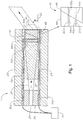
FIGURE 1 illustrates an example of asystem 10 that can electrically steer light in a laser probe according to certain embodiments. In certain embodiments,system 10 may inserted into a human (or other living or previously living) body for medical purposes, such as for ophthalmic surgery. For example,system 10 may be an endoilluminator surgical instrument for projecting light into an interior of an eyeball. - In the illustrated example,
system 10 includes a cannula 20 (or other housing), aninner cylinder 24 disposed withincannula 20, asleeve 26 disposed withininner cylinder 24, and an optical fiber 28 (or other optical waveguide) disposed withinsleeve 26. Electrodes 30 (30a-b) are disposed within the walls ofinner cylinder 24.Optical fiber 28 emits abeam 32.Lens 34 and abeam steering cell 40 are disposed withininner cylinder 24 in the direction ofbeam 32.Beam steering cell 40 comprises, in the direction ofbeam 32, acover plate 42, anelectrode layer 44a, an electro-optical (EO)element 46, aprism 48, and anelectrode layer 44b. In an example of operation,optical fiber 28 emits a light beam travelling in a first direction.Beam steering cell 40 receives one or more voltages and the light beam, and electrically steers the light beam to a second direction. - The housing (e.g., cannula 20) may have any suitable shape and size. The housing may have a tubular (or cylindrical) shape with a
cylindrical axis 22 and any suitable length and diameter, such as a length in the range of one to two inches, an outer diameter (OD) in the range of 0.05 to 0.02 inches, and an inner diameter (ID) in the range of 0.04 to 0.01 inches (but of course can be larger or smaller). For cannulas, the size may depend on the gauge (ga) of the cannula. For example, 20ga cannulas may be approximately 0.0365" in OD and 0.031" in ID; 23ga cannulas may be approximately 0.0255" in OD and 0.021" in ID; and 25ga cannulas may be approximately 0.0205" in OD and 0.0156" in ID. This disclosure contemplates even smaller (higher gauge) cannulas. - In certain embodiments, the housing may have an interior surface that defines an
interior region 50. The surface of the housing may define at least one opening, such a distal end opening 52, and may also define another opening, such a proximal end opening. The housing may comprise any suitable material, e.g., a metal such as stainless steel. In certain embodiments, the housing may be acannula 20 that can be inserted into the body for medical purposes, such as for ophthalmic surgery. -
Inner cylinder 24 disposed withincannula 20 may further defineinterior region 50. In certain embodiments,inner cylinder 24 electrically insulatesinterior region 50 from the region exterior toinner cylinder 24.Inner cylinder 24 may comprise any suitable material, e.g., ceramic.Sleeve 26 disposed withininner cylinder 24 supports and holds the optical waveguide (such as optical fiber 28) in position todirect beam 32 tolens 34. -
Optical fiber 26 is a transparent fiber that operates as a waveguide to transmit light from a laser source to emit alight beam 32.Light beam 32 may be travelling in a first direction, which may substantially coincide withcylindrical axis 22 ofcannula 20.Lens 34 receives and collimateslight beam 32.Lens 34 may be any lens suitable for collimating a light beam, such as a gradient-index (GRIN) lens. -
Beam steering cell 40 electrically steerslight beam 32 from the first direction to a second direction different from the first direction. In certain embodiments,beam steering cell 40 may receive one or more voltages and electrically steer the light beam with theEO material 46 to in response to the voltages. The beam may be steered to a divergence angle θ with respect to acylindrical axis 22 ofcannula 20. Divergence angle θ may have any suitable value, such as a value in the range of 0 to 90 degrees. -
Cover plate 42 ofbeam steering cell 40 may comprise any suitable transparent material, such as glass, and may have any suitable shape and size, such as a flat planar shape with a thickness in the range of 10 to 200 microns. Electrode layers 44 (44a-b) conduct electrical current from apower source 31 to apply voltage toEO element 46.Electrode layers 44 may comprise any suitable conductive material, such as indium tin oxide (ITO). -
EO element 46 changes its refractive index in response to an applied electrical field. Accordingly,EO element 46 may change the direction of a light beam in response to an applied voltage.EO element 46 may comprise any suitable EO material, such as an optically transparent electrically conductive (OTEC) material. Examples of OTEC material are described with reference toFIGURE 2 .Prism 48 is a transparent optical element that refractslight beam 32. -
EO element 46 andprism 48 are configured such that a portion oflight beam 32 passes throughmore EO element 46 than another portion passes through, and less ofprism 48 than the other portion passes through. In the illustrated example, portions 60 (60a-b) of an optical path go throughEO element 46 andprism 48.EO element 46 andprism 48 each have a wedge shape where the length of the optical path through each varies for different parts ofbeam 32.Portion 60a has anOE part 64a andprism part 66a, andportion 60b has aOE part 64b andprism part 66b.OE part 64a is greater thanOE part 64b, andprism part 66a is less thanprism part 66b.EO element 46 andprism 48 may have any suitable size. For example, the thickest portion ofEO element 46 may be in the range of 30 to 600 microns, and the thinnest portion may be in the range of 0 to 100 microns. The thickest portion ofprism 48 may be in the range of 130 to 700 microns, and the thinnest portion may be in the range of 100 to 200 microns. -
Power source 31 supplies electricity to electrodes 30 to apply voltage tobeam steering cell 40 to steerlight beam 32. In certain embodiments,power source 31 may change the voltages to change the direction oflight beam 32 to yield a pattern of emitted light. Examples of this are described in more detail with reference toFIGURE 7 . -
FIGURES 2A and 2B illustrate an example of an electro-optical (EO) material that may be used in a system that electrically steers light according to certain embodiments. In the example,EO material 46 is disposed between electrodes 30. -
EO material 46 may be a liquid crystal (LC) such as a polymer-dispersed liquid crystal (PDLC) material. In PDLC material, tiny circular orquasi-circular LC droplets 70 withLC molecules 74 are immersed within a medium ofhardened polymer 72.Droplets 70 are immobilized withinpolymer 72, butLC molecules 74 withindroplets 70 are free to rotate. In the absence of an electric field, the orientations ofLC molecules 74 tend to be random, and the resulting effective refractive index ofLC droplet 70 is nLC (V = 0) = nLCo (FIGURE 2A ). - As increasing voltage is applied to the PDLC material,
LC molecules 74 tend to orient more and more along the direction of the electric field, and the refractive index ofdroplet 70 changes from nLCo to nLC(V). At maximum voltage Vmax,LC molecules 74 have aligned with the electric field, and the refractive ofLC droplet 70 is nLC(Vmax) (FIGURE 2B ). -
LC droplets 70 may be on the order of a wavelength of laser light or smaller to avoid scattering light from the incident beam offLC droplets 70. The PDLC material illuminated by the laser beam appears as an effective medium with an effective refractive index neff, which is dependent on the constant polymer index npolymer and the voltage-dependent LC droplet effective index nLC. Therefore, the effective index neff is also voltage-dependent and varies from neffo at 0 volts to neff-max at Vmax. - In the example of
FIGURE 1 , divergence angle θ may be given by:

- Therefore, the beam can be steered continuously between 0 degrees and θmax, (which typically occurs at Vmax).
-
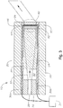
FIGURES 3 and4 illustrate another example of asystem 10 that can electrically steer light in a laser probe according to certain embodiments.System 10 steers light by applying different voltages across different portions ofbeam steering cell 40. In the example,beam steering cell 40 includescover plate 42,electrode layer 44 disposed outwardly fromcover plate 42,OE element 46 disposed outwardly fromelectrode layer 44,electrode layer 90 disposed outwardly fromOE element 46, and acover plate 96. - Electrode layers 44 and 90 apply different voltages across
OE element 46. In certain embodiments,electrode layer 90 comprisesstrip electrodes 92, where at least twostrip electrodes 92 apply different voltages. Astrip electrode 92 may comprise any conductive material, such as ITO. In certain embodiments,strip electrodes 92 are individually addressable to yield monotonically changing voltage vs. position pattern. -
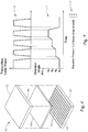
FIGURES 5A through 5D illustrate an example of voltages applied tobeam steering cell 40 ofFIGURES 3 and4 according to certain embodiments. The figures show how voltages may be applied tobeam steering cell 40 withstrip electrodes 92 to yield a monotonically changing refractive index versus position pattern. -
FIGURE 5A illustrates an example of abeam steering cell 40 withstrip electrodes 92 and sides A and B.Different strip electrodes 92 may apply different voltages to yield a voltage vs. position pattern. Any suitable voltages may be applied. In the example ofFIGURE 5B , the voltages monotonically change with respect to position from side A to side B, e.g., from a voltage in a range of 10 to 250 volts at side A to a voltage in a range of 0 to 5 volts at side B. The voltage vs. position pattern yields a refractive index vs. position pattern. In the example ofFIGURE 5C , the refractive index monotonically changes with respect to position from side A to side B, e.g., from a refractive index in a range of 1.5 to 1.8 at side A to a refractive index in a range of 1.4 to 1.6 at side B. Accordingly,beam steering cell 40 may operate similarly to a wedge-shaped prism ofFIGURE 5D . - The time for a beam to pass through an optical element is inversely dependent on its optical thickness, which is product of the refractive index and thickness of
cell 40 where the beam is traveling. In the illustrated example, the cell thickness is constant across theentire cell 40 and the refractive index varies acrosscell 40, so the optical thickness, and thus the beam transit time, varies monotonically across the cell. The refractive index is lower on the B side of the cell than the A side, so the beam passes through the B side of the cell faster than on the A side. - In certain situations, incident and emitted beams are collimated. When a collimated beam is normally incident on
cell 40 ofFIGURE 5A , the beam reaches anouter surface 98 ofplate 96 on the B side more quickly than it does on the A side because the reflective index is lower on the B side than on the A side. According to optical principles, the beam emerging fromsurface 98 should be planar, with the wavefront perpendicular to the beam direction. Thus, there is beam steering to the A side as the beam exitscell 40. Accordingly, rays between the planar wave front incident on the cell and the planar wave front exiting the cell have the same total optical path length. The same principle applies for the wedge prism, except in that case, the refractive index is constant and the prism thickness varies with lateral position. But the end result is the same: the planar striped LC cell has the same effect on incident light as a constant-index wedge prism. -
FIGURE 6 illustrates an example of asystem 10 that can electrically steer light in two dimensions according to certain embodiments. Two or more beam steering cells 40 (40a-b) may be positioned in different directions to steerlight beam 32 in two dimensions. For example, twobeam steering cells 40 may be position orthogonally such thatcell 40a movesbeam 32 along a first coordinate axis andcell 40b movesbeam 32 along a second coordinate axis orthogonal to the first coordinate axis to allow for two-dimensional beam steering. -
FIGURE 7 illustrates an example of a pattern of diversion angles that may be used to yield a pattern of emitted light. In certain embodiments, the voltages applied tobeam steering cell 40 may be changed to change divergence angle θ. In the example,graph 112 shows divergence angle θ changing with respect to time from θi = θ1 to θ4. The changes in divergence angle θ may yield a particular pattern of emitted light. In the example,graph 114 shows the pattern of emitted light resulting from the changes in divergence angle θ. In certain embodiments, the laser power may be synchronized to be on when divergence angle θ is at a desired angle θi, but off when divergence angle θ transitioning between desired angles θi. The resulting light pattern may have clearer, less blurry, spots. - In certain embodiments, the changes in voltage may be performed by a component that may include an interface, logic, memory, and/or other suitable element, any of which may include hardware and/or software. An interface can receive input, send output, process the input and/or output, and/or perform other suitable operations. Logic can perform the operations of a component, for example, execute instructions to generate output from input. Logic may be encoded in memory and may perform operations when executed by a computer. Logic may be a processor, such as one or more computers, one or more microprocessors, one or more applications, and/or other logic. A memory can store information and may comprise one or more tangible, computer-readable, and/or computer-executable storage medium. Examples of memory include computer memory (for example, Random Access Memory (RAM) or Read Only Memory (ROM)), mass storage media (for example, a hard disk), removable storage media (for example, a Compact Disk (CD) or a Digital Video Disk (DVD)), database and/or network storage (for example, a server), and/or other computer-readable media.
- Although this disclosure has been described in terms of certain embodiments, modifications (such as changes, substitutions, additions, omissions, and/or other modifications) of the embodiments will be apparent to those skilled in the art. Accordingly, modifications may be made to the embodiments without departing from the scope of the invention. For example, modifications may be made to the systems and apparatuses disclosed herein. The components of the systems and apparatuses may be integrated or separated, and the operations of the systems and apparatuses may be performed by more, fewer, or other components. As another example, modifications may be made to the methods disclosed herein. The methods may include more, fewer, or other steps, and the steps may be performed in any suitable order.
- Other modifications are possible without departing from the scope of the invention. For example, the description illustrates embodiments in particular practical applications, yet other applications will be apparent to those skilled in the art. In addition, future developments will occur in the arts discussed herein, and the disclosed systems, apparatuses, and methods will be utilized with such future developments.
- The scope of the invention should not be determined with reference to the description. In accordance with patent statutes, the description explains and illustrates the principles and modes of operation of the invention using exemplary embodiments. The description enables others skilled in the art to utilize the systems, apparatuses, and methods in various embodiments and with various modifications, but should not be used to determine the scope of the invention.
- The scope of the invention should be determined with reference to the claims and the full scope of equivalents to which the claims are entitled. All claims terms should be given their broadest reasonable constructions and their ordinary meanings as understood by those skilled in the art, unless an explicit indication to the contrary is made herein. For example, use of the singular articles such as "a," "the," etc. should be read to recite one or more of the indicated elements, unless a claim recites an explicit limitation to the contrary. As another example, "each" refers to each member of a set or each member of a subset of a set, where a set may include zero, one, or more than one element. In sum, the invention is capable of modification, and the scope of the invention should be determined, not with reference to the description, but with reference to the claims and their full scope of equivalents.
Claims (10)
- A system (10) comprising:a housing (20) having a tubular shape defining an interior region and at least one opening;an optical waveguide (28) disposed within the interior region, the optical waveguide configured to emit a light beam (32) travelling in a first direction; anda beam steering cell (40) disposed within the housing, the beam steering cell comprising an electro-optical (EO) element (46) that includes an electro-optical material that changes its refractive index in response to applied voltage, the beam steering cell configured to:receive one or more voltages; andelectrically steer the light beam with the EO material to a second direction different than the first direction in response to the one or more voltages;characterized in that the beam steering cell (40) comprises:a first electrode layer (44a);a wedge-shaped EO element (46) comprising the EO material and disposed outwardly from the first electrode layer;a prism (48) disposed outwardly from the EO element, wherein an optical path through the EO element and the prism defines a first portion (60a) comprising a first EO part (64a) and a first prism part (66a) and a second portion (60b) comprising a second EO part (64b) and a second prism part (66b), the first EO part being greater than the second EO part; anda second electrode layer (44b) disposed outwardly from the prism.
- The system of Claim 1, the housing (20) comprising a cannula.
- The system of Claim 1, the EO material comprising a polymer-dispersed liquid crystal (PDLC) material.
- The system of Claim 1, wherein each electrode layer (44a,44b) comprises an optically transparent electrically conductive (OTEC) material.
- The system of Claim 1, further comprising:
a power source (31) configured to apply the one or more voltages. - The system of Claim 1, further comprising:
a power source (31) configured to change the one or more voltages to change the second angle to yield a pattern of emitted light. - The system of any one of claims 1 to 6, comprising:
a plurality of beam steering cells (40) disposed within the housing, a first beam steering cell positioned orthogonally with respect to a second beam steering cell, each beam steering cell comprising an electro-optical (EO) material, each beam steering cell configured to:receive one or more voltages; andelectrically steer the light beam with the EO material to a second direction in response to the one or more voltages. - A method comprising:emitting, by an optical waveguide disposed within an interior region of a housing, a light beam travelling in a first direction, the housing having a tubular shape defining the interior region and at least one opening;receiving, by a beam steering cell disposed within the housing, one or more voltages, wherein the beam steering cell (40) comprises:a first electrode layer (44a);a wedge-shaped EO element (46) comprising the EO material and disposed outwardly from the first electrode layer;a prism (48) disposed outwardly from the EO element, wherein an optical path through the EO element and the prism defines a first portion (60a) comprising a first EO part (64a) and a first prism part (66a) and a second portion (60b) comprising a second EO part (64b) and a second prism part (66b), the first EO part being greater than the second EO part; anda second electrode layer (44b) disposed outwardly from the prism;receiving, by the beam steering cell, the light beam; andelectrically steering the light beam with the EO material to a second direction in response to the one or more voltages, by applying the one or more voltages to the EO element (46), an optical path through the EO element having a first portion (60a) comprising a first EO part (64a) and a second portion (60b) comprising a second EO part (64b), the first EO part having a greater thickness than the second EO part.
- The method of Claim 8, further comprising:
changing the one or more voltages to change the second angle. - The method of Claim 8, further comprising:
changing the one or more voltages to change the second angle to yield a pattern of emitted light.
Applications Claiming Priority (2)
| Application Number | Priority Date | Filing Date | Title |
|---|---|---|---|
| US13/226,675 US9086608B2 (en) | 2011-09-07 | 2011-09-07 | Laser probe with an electrically steerable light beam |
| PCT/US2012/043504 WO2013036314A2 (en) | 2011-09-07 | 2012-06-21 | Laser probe with an electrically steerable light beam |
Publications (3)
| Publication Number | Publication Date |
|---|---|
| EP2753975A2 EP2753975A2 (en) | 2014-07-16 |
| EP2753975A4 EP2753975A4 (en) | 2015-01-14 |
| EP2753975B1 true EP2753975B1 (en) | 2018-09-19 |
Family
ID=47752926
Family Applications (1)
| Application Number | Title | Priority Date | Filing Date |
|---|---|---|---|
| EP12830381.5A Not-in-force EP2753975B1 (en) | 2011-09-07 | 2012-06-21 | Laser probe with an electrically steerable light beam |
Country Status (10)
| Country | Link |
|---|---|
| US (1) | US9086608B2 (en) |
| EP (1) | EP2753975B1 (en) |
| JP (1) | JP6185471B2 (en) |
| CN (1) | CN103930824A (en) |
| AU (1) | AU2012304914B2 (en) |
| BR (1) | BR112014005230A2 (en) |
| CA (1) | CA2845236C (en) |
| ES (1) | ES2702548T3 (en) |
| RU (1) | RU2608324C2 (en) |
| WO (1) | WO2013036314A2 (en) |
Families Citing this family (5)
| Publication number | Priority date | Publication date | Assignee | Title |
|---|---|---|---|---|
| US9849034B2 (en) | 2011-11-07 | 2017-12-26 | Alcon Research, Ltd. | Retinal laser surgery |
| US8939964B2 (en) * | 2011-12-01 | 2015-01-27 | Alcon Research, Ltd. | Electrically switchable multi-spot laser probe |
| US8888734B2 (en) | 2012-06-05 | 2014-11-18 | Alcon Research, Ltd. | Functionally graded material tube and method for use of the same in implantation |
| US9413461B2 (en) * | 2013-11-04 | 2016-08-09 | California Institute Of Technology | High bandwidth optical links for micro-satellite support |
| CN104932087A (en) * | 2015-05-15 | 2015-09-23 | 奥普多威(开曼)控股有限公司 | Integrated optical coherent detection probe |
Citations (2)
| Publication number | Priority date | Publication date | Assignee | Title |
|---|---|---|---|---|
| EP1105765A1 (en) * | 1998-08-19 | 2001-06-13 | Boston Scientific Limited | Optical scanning and imaging system and method |
| JP2003195274A (en) * | 2001-12-28 | 2003-07-09 | Ricoh Co Ltd | Light deflector element, optical path switching device and image display device |
Family Cites Families (20)
| Publication number | Priority date | Publication date | Assignee | Title |
|---|---|---|---|---|
| JPS61125337A (en) * | 1984-11-21 | 1986-06-13 | オリンパス光学工業株式会社 | Laser knife apparatus |
| US5363126A (en) * | 1992-09-25 | 1994-11-08 | Xerox Corporation | Device and apparatus for high speed tracking in a raster output scanner |
| US6821457B1 (en) * | 1998-07-29 | 2004-11-23 | Science Applications International Corporation | Electrically switchable polymer-dispersed liquid crystal materials including switchable optical couplers and reconfigurable optical interconnects |
| US6031658A (en) | 1998-09-25 | 2000-02-29 | University Of Central Florida | Digital control polarization based optical scanner |
| US6984230B2 (en) | 2000-04-07 | 2006-01-10 | Synergetics, Inc. | Directional laser probe |
| US6832028B2 (en) * | 2002-10-08 | 2004-12-14 | Innovative Technology Licensing, Llc | Liquid crystal adaptive coupler for steering a light beam relative to a light-receiving end of an optical waveguide |
| US6958851B2 (en) | 2003-12-03 | 2005-10-25 | Northrop Grumman Corporation | Electronically modulated prism |
| US8463080B1 (en) * | 2004-01-22 | 2013-06-11 | Vescent Photonics, Inc. | Liquid crystal waveguide having two or more control voltages for controlling polarized light |
| EP1612596A1 (en) | 2004-06-29 | 2006-01-04 | Fraunhofer-Gesellschaft zur Förderung der angewandten Forschung e.V. | High-efficient, tuneable and switchable optical elements based on polymer-liquid crystal composites and films, mixtures and a method for their production |
| US7411724B2 (en) * | 2004-12-06 | 2008-08-12 | Northrop Grumman Corporation | Electro-optic crystal, diffraction-based, beam-steering element |
| US7400787B2 (en) | 2005-04-07 | 2008-07-15 | Photonic Systems, Inc. | Optical modulator with coupled coplanar strip electrode and domain inversion |
| US20070024978A1 (en) | 2005-08-01 | 2007-02-01 | Jackson John E | Conformal beam steering devices having a minimal volume and window area utilizing risley prisms and diffraction gratings |
| US10098781B2 (en) | 2006-03-24 | 2018-10-16 | Topcon Medical Laser Systems Inc. | Multi-spot optical fiber endophotocoagulation probe |
| US7566173B2 (en) | 2007-07-09 | 2009-07-28 | Alcon, Inc. | Multi-spot ophthalmic laser probe |
| US8903475B2 (en) | 2009-03-08 | 2014-12-02 | Oprobe, Llc | Multi-function optical probe system for medical and veterinary applications |
| JP5325640B2 (en) * | 2009-04-08 | 2013-10-23 | オリンパス株式会社 | Endoscope apparatus and optical scanning method thereof |
| US8515217B2 (en) | 2009-09-02 | 2013-08-20 | Alcatel Lucent | Vertical optically emitting photonic devices with electronic steering capability |
| JP5809163B2 (en) | 2009-12-15 | 2015-11-10 | アルコン リサーチ, リミテッド | Multi-spot laser probe |
| US20120075639A1 (en) * | 2010-09-24 | 2012-03-29 | Jeffrey Brennan | Imaging systems and methods incorporating non-mechanical scanning beam actuation |
| CN102207514B (en) * | 2011-03-23 | 2013-07-17 | 吉林大学 | Electrooptical probe based on fluid electrooptical materials, and method of using electrooptical probe to detect electric field |
-
2011
- 2011-09-07 US US13/226,675 patent/US9086608B2/en active Active
-
2012
- 2012-06-21 CA CA2845236A patent/CA2845236C/en not_active Expired - Fee Related
- 2012-06-21 BR BR112014005230A patent/BR112014005230A2/en not_active Application Discontinuation
- 2012-06-21 EP EP12830381.5A patent/EP2753975B1/en not_active Not-in-force
- 2012-06-21 AU AU2012304914A patent/AU2012304914B2/en not_active Ceased
- 2012-06-21 ES ES12830381T patent/ES2702548T3/en active Active
- 2012-06-21 CN CN201280043495.5A patent/CN103930824A/en active Pending
- 2012-06-21 JP JP2014529712A patent/JP6185471B2/en not_active Expired - Fee Related
- 2012-06-21 WO PCT/US2012/043504 patent/WO2013036314A2/en active Application Filing
- 2012-06-21 RU RU2014113388A patent/RU2608324C2/en not_active IP Right Cessation
Patent Citations (2)
| Publication number | Priority date | Publication date | Assignee | Title |
|---|---|---|---|---|
| EP1105765A1 (en) * | 1998-08-19 | 2001-06-13 | Boston Scientific Limited | Optical scanning and imaging system and method |
| JP2003195274A (en) * | 2001-12-28 | 2003-07-09 | Ricoh Co Ltd | Light deflector element, optical path switching device and image display device |
Also Published As
| Publication number | Publication date |
|---|---|
| BR112014005230A2 (en) | 2017-04-11 |
| EP2753975A2 (en) | 2014-07-16 |
| WO2013036314A3 (en) | 2014-05-01 |
| CA2845236A1 (en) | 2013-03-14 |
| AU2012304914A1 (en) | 2014-03-06 |
| US20130057821A1 (en) | 2013-03-07 |
| WO2013036314A2 (en) | 2013-03-14 |
| ES2702548T3 (en) | 2019-03-01 |
| AU2012304914B2 (en) | 2015-07-02 |
| CN103930824A (en) | 2014-07-16 |
| RU2608324C2 (en) | 2017-01-17 |
| CA2845236C (en) | 2019-08-20 |
| US9086608B2 (en) | 2015-07-21 |
| JP6185471B2 (en) | 2017-08-23 |
| JP2014529103A (en) | 2014-10-30 |
| RU2014113388A (en) | 2015-10-20 |
| EP2753975A4 (en) | 2015-01-14 |
Similar Documents
| Publication | Publication Date | Title |
|---|---|---|
| US9910338B2 (en) | Electrically switchable multi-spot laser probe | |
| EP2753975B1 (en) | Laser probe with an electrically steerable light beam | |
| US7324287B1 (en) | Multi-fluid lenses and optical devices incorporating the same | |
| US10585330B2 (en) | Liquid crystal light deflector and holographic display having the liquid crystal light deflector | |
| JP2009237276A (en) | Optical waveguide | |
| Kabanova et al. | Electrically controlled waveguide liquid-crystal elements | |
| JP2014529103A5 (en) | ||
| US20210116776A1 (en) | Liquid crystal mixtures for pitch variable optical elements | |
| US20140194750A1 (en) | Optical zoom probe | |
| KR102607856B1 (en) | 2D steering device | |
| US20220397791A1 (en) | Optical layer and optical system | |
| KR102208740B1 (en) | Beam steering apparatus using plasmonics | |
| US9411103B2 (en) | Contact focusing hollow-core fiber microprobes | |
| TWI727542B (en) | Electrowetting controlled optical scanning probe | |
| US20190302492A1 (en) | Light modulator, optical observation device and optical irradiation device | |
| KR20220058285A (en) | Beam deflector and 3-dimensional display device including the same | |
| US20200019037A1 (en) | Mapping optics for liquid crystal beamsteerer | |
| KR20230004260A (en) | Laser processing apparatus and laser processing method | |
| CN105954869A (en) | Light path selector based on double liquid lens and realization method thereof |
Legal Events
| Date | Code | Title | Description |
|---|---|---|---|
| PUAI | Public reference made under article 153(3) epc to a published international application that has entered the european phase |
Free format text: ORIGINAL CODE: 0009012 |
|
| 17P | Request for examination filed |
Effective date: 20140213 |
|
| AK | Designated contracting states |
Kind code of ref document: A2 Designated state(s): AL AT BE BG CH CY CZ DE DK EE ES FI FR GB GR HR HU IE IS IT LI LT LU LV MC MK MT NL NO PL PT RO RS SE SI SK SM TR |
|
| A4 | Supplementary search report drawn up and despatched |
Effective date: 20141215 |
|
| RIC1 | Information provided on ipc code assigned before grant |
Ipc: G02F 1/035 20060101ALI20141209BHEP Ipc: G02F 1/03 20060101AFI20141209BHEP |
|
| DAX | Request for extension of the european patent (deleted) | ||
| 17Q | First examination report despatched |
Effective date: 20160922 |
|
| STAA | Information on the status of an ep patent application or granted ep patent |
Free format text: STATUS: EXAMINATION IS IN PROGRESS |
|
| GRAP | Despatch of communication of intention to grant a patent |
Free format text: ORIGINAL CODE: EPIDOSNIGR1 |
|
| STAA | Information on the status of an ep patent application or granted ep patent |
Free format text: STATUS: GRANT OF PATENT IS INTENDED |
|
| INTG | Intention to grant announced |
Effective date: 20180515 |
|
| GRAS | Grant fee paid |
Free format text: ORIGINAL CODE: EPIDOSNIGR3 |
|
| GRAA | (expected) grant |
Free format text: ORIGINAL CODE: 0009210 |
|
| STAA | Information on the status of an ep patent application or granted ep patent |
Free format text: STATUS: THE PATENT HAS BEEN GRANTED |
|
| AK | Designated contracting states |
Kind code of ref document: B1 Designated state(s): AL AT BE BG CH CY CZ DE DK EE ES FI FR GB GR HR HU IE IS IT LI LT LU LV MC MK MT NL NO PL PT RO RS SE SI SK SM TR |
|
| REG | Reference to a national code |
Ref country code: GB Ref legal event code: FG4D |
|
| REG | Reference to a national code |
Ref country code: CH Ref legal event code: EP |
|
| REG | Reference to a national code |
Ref country code: AT Ref legal event code: REF Ref document number: 1043927 Country of ref document: AT Kind code of ref document: T Effective date: 20181015 |
|
| REG | Reference to a national code |
Ref country code: IE Ref legal event code: FG4D |
|
| REG | Reference to a national code |
Ref country code: DE Ref legal event code: R096 Ref document number: 602012051374 Country of ref document: DE |
|
| REG | Reference to a national code |
Ref country code: NL Ref legal event code: MP Effective date: 20180919 |
|
| PG25 | Lapsed in a contracting state [announced via postgrant information from national office to epo] |
Ref country code: NO Free format text: LAPSE BECAUSE OF FAILURE TO SUBMIT A TRANSLATION OF THE DESCRIPTION OR TO PAY THE FEE WITHIN THE PRESCRIBED TIME-LIMIT Effective date: 20181219 Ref country code: LT Free format text: LAPSE BECAUSE OF FAILURE TO SUBMIT A TRANSLATION OF THE DESCRIPTION OR TO PAY THE FEE WITHIN THE PRESCRIBED TIME-LIMIT Effective date: 20180919 Ref country code: BG Free format text: LAPSE BECAUSE OF FAILURE TO SUBMIT A TRANSLATION OF THE DESCRIPTION OR TO PAY THE FEE WITHIN THE PRESCRIBED TIME-LIMIT Effective date: 20181219 Ref country code: FI Free format text: LAPSE BECAUSE OF FAILURE TO SUBMIT A TRANSLATION OF THE DESCRIPTION OR TO PAY THE FEE WITHIN THE PRESCRIBED TIME-LIMIT Effective date: 20180919 Ref country code: GR Free format text: LAPSE BECAUSE OF FAILURE TO SUBMIT A TRANSLATION OF THE DESCRIPTION OR TO PAY THE FEE WITHIN THE PRESCRIBED TIME-LIMIT Effective date: 20181220 Ref country code: RS Free format text: LAPSE BECAUSE OF FAILURE TO SUBMIT A TRANSLATION OF THE DESCRIPTION OR TO PAY THE FEE WITHIN THE PRESCRIBED TIME-LIMIT Effective date: 20180919 Ref country code: SE Free format text: LAPSE BECAUSE OF FAILURE TO SUBMIT A TRANSLATION OF THE DESCRIPTION OR TO PAY THE FEE WITHIN THE PRESCRIBED TIME-LIMIT Effective date: 20180919 |
|
| REG | Reference to a national code |
Ref country code: LT Ref legal event code: MG4D |
|
| PG25 | Lapsed in a contracting state [announced via postgrant information from national office to epo] |
Ref country code: AL Free format text: LAPSE BECAUSE OF FAILURE TO SUBMIT A TRANSLATION OF THE DESCRIPTION OR TO PAY THE FEE WITHIN THE PRESCRIBED TIME-LIMIT Effective date: 20180919 Ref country code: LV Free format text: LAPSE BECAUSE OF FAILURE TO SUBMIT A TRANSLATION OF THE DESCRIPTION OR TO PAY THE FEE WITHIN THE PRESCRIBED TIME-LIMIT Effective date: 20180919 Ref country code: HR Free format text: LAPSE BECAUSE OF FAILURE TO SUBMIT A TRANSLATION OF THE DESCRIPTION OR TO PAY THE FEE WITHIN THE PRESCRIBED TIME-LIMIT Effective date: 20180919 |
|
| REG | Reference to a national code |
Ref country code: ES Ref legal event code: FG2A Ref document number: 2702548 Country of ref document: ES Kind code of ref document: T3 Effective date: 20190301 |
|
| REG | Reference to a national code |
Ref country code: AT Ref legal event code: MK05 Ref document number: 1043927 Country of ref document: AT Kind code of ref document: T Effective date: 20180919 |
|
| PG25 | Lapsed in a contracting state [announced via postgrant information from national office to epo] |
Ref country code: PL Free format text: LAPSE BECAUSE OF FAILURE TO SUBMIT A TRANSLATION OF THE DESCRIPTION OR TO PAY THE FEE WITHIN THE PRESCRIBED TIME-LIMIT Effective date: 20180919 Ref country code: EE Free format text: LAPSE BECAUSE OF FAILURE TO SUBMIT A TRANSLATION OF THE DESCRIPTION OR TO PAY THE FEE WITHIN THE PRESCRIBED TIME-LIMIT Effective date: 20180919 Ref country code: AT Free format text: LAPSE BECAUSE OF FAILURE TO SUBMIT A TRANSLATION OF THE DESCRIPTION OR TO PAY THE FEE WITHIN THE PRESCRIBED TIME-LIMIT Effective date: 20180919 Ref country code: IS Free format text: LAPSE BECAUSE OF FAILURE TO SUBMIT A TRANSLATION OF THE DESCRIPTION OR TO PAY THE FEE WITHIN THE PRESCRIBED TIME-LIMIT Effective date: 20190119 Ref country code: RO Free format text: LAPSE BECAUSE OF FAILURE TO SUBMIT A TRANSLATION OF THE DESCRIPTION OR TO PAY THE FEE WITHIN THE PRESCRIBED TIME-LIMIT Effective date: 20180919 Ref country code: NL Free format text: LAPSE BECAUSE OF FAILURE TO SUBMIT A TRANSLATION OF THE DESCRIPTION OR TO PAY THE FEE WITHIN THE PRESCRIBED TIME-LIMIT Effective date: 20180919 Ref country code: CZ Free format text: LAPSE BECAUSE OF FAILURE TO SUBMIT A TRANSLATION OF THE DESCRIPTION OR TO PAY THE FEE WITHIN THE PRESCRIBED TIME-LIMIT Effective date: 20180919 |
|
| PG25 | Lapsed in a contracting state [announced via postgrant information from national office to epo] |
Ref country code: SK Free format text: LAPSE BECAUSE OF FAILURE TO SUBMIT A TRANSLATION OF THE DESCRIPTION OR TO PAY THE FEE WITHIN THE PRESCRIBED TIME-LIMIT Effective date: 20180919 Ref country code: PT Free format text: LAPSE BECAUSE OF FAILURE TO SUBMIT A TRANSLATION OF THE DESCRIPTION OR TO PAY THE FEE WITHIN THE PRESCRIBED TIME-LIMIT Effective date: 20190119 Ref country code: SM Free format text: LAPSE BECAUSE OF FAILURE TO SUBMIT A TRANSLATION OF THE DESCRIPTION OR TO PAY THE FEE WITHIN THE PRESCRIBED TIME-LIMIT Effective date: 20180919 |
|
| REG | Reference to a national code |
Ref country code: DE Ref legal event code: R097 Ref document number: 602012051374 Country of ref document: DE |
|
| PLBE | No opposition filed within time limit |
Free format text: ORIGINAL CODE: 0009261 |
|
| STAA | Information on the status of an ep patent application or granted ep patent |
Free format text: STATUS: NO OPPOSITION FILED WITHIN TIME LIMIT |
|
| PG25 | Lapsed in a contracting state [announced via postgrant information from national office to epo] |
Ref country code: DK Free format text: LAPSE BECAUSE OF FAILURE TO SUBMIT A TRANSLATION OF THE DESCRIPTION OR TO PAY THE FEE WITHIN THE PRESCRIBED TIME-LIMIT Effective date: 20180919 |
|
| PGFP | Annual fee paid to national office [announced via postgrant information from national office to epo] |
Ref country code: IT Payment date: 20190620 Year of fee payment: 8 Ref country code: DE Payment date: 20190612 Year of fee payment: 8 |
|
| 26N | No opposition filed |
Effective date: 20190620 |
|
| PGFP | Annual fee paid to national office [announced via postgrant information from national office to epo] |
Ref country code: FR Payment date: 20190604 Year of fee payment: 8 |
|
| PG25 | Lapsed in a contracting state [announced via postgrant information from national office to epo] |
Ref country code: SI Free format text: LAPSE BECAUSE OF FAILURE TO SUBMIT A TRANSLATION OF THE DESCRIPTION OR TO PAY THE FEE WITHIN THE PRESCRIBED TIME-LIMIT Effective date: 20180919 |
|
| PGFP | Annual fee paid to national office [announced via postgrant information from national office to epo] |
Ref country code: GB Payment date: 20190619 Year of fee payment: 8 Ref country code: ES Payment date: 20190701 Year of fee payment: 8 |
|
| PG25 | Lapsed in a contracting state [announced via postgrant information from national office to epo] |
Ref country code: MC Free format text: LAPSE BECAUSE OF FAILURE TO SUBMIT A TRANSLATION OF THE DESCRIPTION OR TO PAY THE FEE WITHIN THE PRESCRIBED TIME-LIMIT Effective date: 20180919 |
|
| REG | Reference to a national code |
Ref country code: CH Ref legal event code: PL |
|
| REG | Reference to a national code |
Ref country code: GB Ref legal event code: 732E Free format text: REGISTERED BETWEEN 20200109 AND 20200115 |
|
| REG | Reference to a national code |
Ref country code: GB Ref legal event code: 732E Free format text: REGISTERED BETWEEN 20200116 AND 20200122 |
|
| REG | Reference to a national code |
Ref country code: DE Ref legal event code: R081 Ref document number: 602012051374 Country of ref document: DE Owner name: ALCON INC., CH Free format text: FORMER OWNER: ALCON RESEARCH, LTD., FORT WORTH, TEX., US |
|
| REG | Reference to a national code |
Ref country code: BE Ref legal event code: MM Effective date: 20190630 |
|
| PG25 | Lapsed in a contracting state [announced via postgrant information from national office to epo] |
Ref country code: TR Free format text: LAPSE BECAUSE OF FAILURE TO SUBMIT A TRANSLATION OF THE DESCRIPTION OR TO PAY THE FEE WITHIN THE PRESCRIBED TIME-LIMIT Effective date: 20180919 |
|
| REG | Reference to a national code |
Ref country code: ES Ref legal event code: PC2A Owner name: ALCON INC. Effective date: 20200407 |
|
| PG25 | Lapsed in a contracting state [announced via postgrant information from national office to epo] |
Ref country code: IE Free format text: LAPSE BECAUSE OF NON-PAYMENT OF DUE FEES Effective date: 20190621 |
|
| PG25 | Lapsed in a contracting state [announced via postgrant information from national office to epo] |
Ref country code: LI Free format text: LAPSE BECAUSE OF NON-PAYMENT OF DUE FEES Effective date: 20190630 Ref country code: LU Free format text: LAPSE BECAUSE OF NON-PAYMENT OF DUE FEES Effective date: 20190621 Ref country code: BE Free format text: LAPSE BECAUSE OF NON-PAYMENT OF DUE FEES Effective date: 20190630 Ref country code: CH Free format text: LAPSE BECAUSE OF NON-PAYMENT OF DUE FEES Effective date: 20190630 |
|
| REG | Reference to a national code |
Ref country code: DE Ref legal event code: R119 Ref document number: 602012051374 Country of ref document: DE |
|
| GBPC | Gb: european patent ceased through non-payment of renewal fee |
Effective date: 20200621 |
|
| PG25 | Lapsed in a contracting state [announced via postgrant information from national office to epo] |
Ref country code: FR Free format text: LAPSE BECAUSE OF NON-PAYMENT OF DUE FEES Effective date: 20200630 Ref country code: GB Free format text: LAPSE BECAUSE OF NON-PAYMENT OF DUE FEES Effective date: 20200621 |
|
| PG25 | Lapsed in a contracting state [announced via postgrant information from national office to epo] |
Ref country code: CY Free format text: LAPSE BECAUSE OF FAILURE TO SUBMIT A TRANSLATION OF THE DESCRIPTION OR TO PAY THE FEE WITHIN THE PRESCRIBED TIME-LIMIT Effective date: 20180919 Ref country code: DE Free format text: LAPSE BECAUSE OF NON-PAYMENT OF DUE FEES Effective date: 20210101 |
|
| PG25 | Lapsed in a contracting state [announced via postgrant information from national office to epo] |
Ref country code: HU Free format text: LAPSE BECAUSE OF FAILURE TO SUBMIT A TRANSLATION OF THE DESCRIPTION OR TO PAY THE FEE WITHIN THE PRESCRIBED TIME-LIMIT; INVALID AB INITIO Effective date: 20120621 Ref country code: MT Free format text: LAPSE BECAUSE OF FAILURE TO SUBMIT A TRANSLATION OF THE DESCRIPTION OR TO PAY THE FEE WITHIN THE PRESCRIBED TIME-LIMIT Effective date: 20180919 |
|
| PG25 | Lapsed in a contracting state [announced via postgrant information from national office to epo] |
Ref country code: IT Free format text: LAPSE BECAUSE OF NON-PAYMENT OF DUE FEES Effective date: 20200621 |
|
| PG25 | Lapsed in a contracting state [announced via postgrant information from national office to epo] |
Ref country code: ES Free format text: LAPSE BECAUSE OF NON-PAYMENT OF DUE FEES Effective date: 20200622 |
|
| PG25 | Lapsed in a contracting state [announced via postgrant information from national office to epo] |
Ref country code: MK Free format text: LAPSE BECAUSE OF FAILURE TO SUBMIT A TRANSLATION OF THE DESCRIPTION OR TO PAY THE FEE WITHIN THE PRESCRIBED TIME-LIMIT Effective date: 20180919 |