EP2753975B1 - Lasersonde mit einem elektrisch verstellbaren lichtbündel - Google Patents
Lasersonde mit einem elektrisch verstellbaren lichtbündel Download PDFInfo
- Publication number
- EP2753975B1 EP2753975B1 EP12830381.5A EP12830381A EP2753975B1 EP 2753975 B1 EP2753975 B1 EP 2753975B1 EP 12830381 A EP12830381 A EP 12830381A EP 2753975 B1 EP2753975 B1 EP 2753975B1
- Authority
- EP
- European Patent Office
- Prior art keywords
- voltages
- prism
- beam steering
- steering cell
- disposed
- Prior art date
- Legal status (The legal status is an assumption and is not a legal conclusion. Google has not performed a legal analysis and makes no representation as to the accuracy of the status listed.)
- Not-in-force
Links
Images


Classifications
-
- G—PHYSICS
- G02—OPTICS
- G02F—OPTICAL DEVICES OR ARRANGEMENTS FOR THE CONTROL OF LIGHT BY MODIFICATION OF THE OPTICAL PROPERTIES OF THE MEDIA OF THE ELEMENTS INVOLVED THEREIN; NON-LINEAR OPTICS; FREQUENCY-CHANGING OF LIGHT; OPTICAL LOGIC ELEMENTS; OPTICAL ANALOGUE/DIGITAL CONVERTERS
- G02F1/00—Devices or arrangements for the control of the intensity, colour, phase, polarisation or direction of light arriving from an independent light source, e.g. switching, gating or modulating; Non-linear optics
- G02F1/29—Devices or arrangements for the control of the intensity, colour, phase, polarisation or direction of light arriving from an independent light source, e.g. switching, gating or modulating; Non-linear optics for the control of the position or the direction of light beams, i.e. deflection
-
- G—PHYSICS
- G02—OPTICS
- G02F—OPTICAL DEVICES OR ARRANGEMENTS FOR THE CONTROL OF LIGHT BY MODIFICATION OF THE OPTICAL PROPERTIES OF THE MEDIA OF THE ELEMENTS INVOLVED THEREIN; NON-LINEAR OPTICS; FREQUENCY-CHANGING OF LIGHT; OPTICAL LOGIC ELEMENTS; OPTICAL ANALOGUE/DIGITAL CONVERTERS
- G02F1/00—Devices or arrangements for the control of the intensity, colour, phase, polarisation or direction of light arriving from an independent light source, e.g. switching, gating or modulating; Non-linear optics
- G02F1/01—Devices or arrangements for the control of the intensity, colour, phase, polarisation or direction of light arriving from an independent light source, e.g. switching, gating or modulating; Non-linear optics for the control of the intensity, phase, polarisation or colour
- G02F1/13—Devices or arrangements for the control of the intensity, colour, phase, polarisation or direction of light arriving from an independent light source, e.g. switching, gating or modulating; Non-linear optics for the control of the intensity, phase, polarisation or colour based on liquid crystals, e.g. single liquid crystal display cells
- G02F1/133—Constructional arrangements; Operation of liquid crystal cells; Circuit arrangements
- G02F1/1333—Constructional arrangements; Manufacturing methods
- G02F1/1334—Constructional arrangements; Manufacturing methods based on polymer dispersed liquid crystals, e.g. microencapsulated liquid crystals
Definitions
- the present disclosure relates generally to laser probes, and more particularly to a laser probe with an electrically steerable light beam.
- Laser probes have one or more optical fibers that emit light beams.
- Laser probes typically use mechanical approaches to steer the emitted light beams.
- an optical fiber may be placed in a tube that can be bent or straightened to emit a light beam in a particular direction.
- prisms rotated by motors may steer light beams passing through the prisms.
- a laser probe may have different optical fibers that direct a light beam in different directions, and a light beam is focused onto a particular fiber to direct the beam in a particular direction.
- Known laser probes may not be able to steer emitted light beams in a satisfactory manner in certain situations.
- the present invention provides a system and method for a laser probe with an electrically steerable light beam, in accordance with claims which follow.
- the laser probe may include a housing, an optical waveguide, and a beam steering cell.
- the housing has a tubular shape defining an interior region.
- the optical waveguide is disposed within the interior region and is configured to emit a light beam travelling in a first direction.
- the beam steering cell is disposed within the housing and comprises an electro-optical (EO) material.
- the beam steering cell is configured to receive one or more voltages and electrically steer the light beam with the OE material to a second direction.
- the laser probe may be a directional laser probe or a multi-spot laser probe.
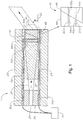
- FIGURE 1 illustrates an example of a system 10 that can electrically steer light in a laser probe according to certain embodiments.
- system 10 may inserted into a human (or other living or previously living) body for medical purposes, such as for ophthalmic surgery.
- system 10 may be an endoilluminator surgical instrument for projecting light into an interior of an eyeball.
- system 10 includes a cannula 20 (or other housing), an inner cylinder 24 disposed within cannula 20, a sleeve 26 disposed within inner cylinder 24, and an optical fiber 28 (or other optical waveguide) disposed within sleeve 26.
- Electrodes 30 (30a-b) are disposed within the walls of inner cylinder 24.
- Optical fiber 28 emits a beam 32.
- Lens 34 and a beam steering cell 40 are disposed within inner cylinder 24 in the direction of beam 32.
- Beam steering cell 40 comprises, in the direction of beam 32, a cover plate 42, an electrode layer 44a, an electro-optical (EO) element 46, a prism 48, and an electrode layer 44b.
- EO electro-optical
- optical fiber 28 emits a light beam travelling in a first direction.
- Beam steering cell 40 receives one or more voltages and the light beam, and electrically steers the light beam to a second direction.
- the housing may have any suitable shape and size.
- the housing may have a tubular (or cylindrical) shape with a cylindrical axis 22 and any suitable length and diameter, such as a length in the range of one to two inches, an outer diameter (OD) in the range of 0.05 to 0.02 inches, and an inner diameter (ID) in the range of 0.04 to 0.01 inches (but of course can be larger or smaller).
- the size may depend on the gauge (ga) of the cannula.
- 20ga cannulas may be approximately 0.0365" in OD and 0.031" in ID; 23ga cannulas may be approximately 0.0255" in OD and 0.021" in ID; and 25ga cannulas may be approximately 0.0205" in OD and 0.0156" in ID.
- This disclosure contemplates even smaller (higher gauge) cannulas.
- the housing may have an interior surface that defines an interior region 50.
- the surface of the housing may define at least one opening, such a distal end opening 52, and may also define another opening, such a proximal end opening.
- the housing may comprise any suitable material, e.g., a metal such as stainless steel.
- the housing may be a cannula 20 that can be inserted into the body for medical purposes, such as for ophthalmic surgery.
- Inner cylinder 24 disposed within cannula 20 may further define interior region 50.
- inner cylinder 24 electrically insulates interior region 50 from the region exterior to inner cylinder 24.
- Inner cylinder 24 may comprise any suitable material, e.g., ceramic.
- Sleeve 26 disposed within inner cylinder 24 supports and holds the optical waveguide (such as optical fiber 28) in position to direct beam 32 to lens 34.
- Optical fiber 26 is a transparent fiber that operates as a waveguide to transmit light from a laser source to emit a light beam 32.
- Light beam 32 may be travelling in a first direction, which may substantially coincide with cylindrical axis 22 of cannula 20.
- Lens 34 receives and collimates light beam 32.
- Lens 34 may be any lens suitable for collimating a light beam, such as a gradient-index (GRIN) lens.
- GRIN gradient-index
- Beam steering cell 40 electrically steers light beam 32 from the first direction to a second direction different from the first direction.
- beam steering cell 40 may receive one or more voltages and electrically steer the light beam with the EO material 46 to in response to the voltages.
- the beam may be steered to a divergence angle ⁇ with respect to a cylindrical axis 22 of cannula 20.
- Divergence angle ⁇ may have any suitable value, such as a value in the range of 0 to 90 degrees.
- Cover plate 42 of beam steering cell 40 may comprise any suitable transparent material, such as glass, and may have any suitable shape and size, such as a flat planar shape with a thickness in the range of 10 to 200 microns.
- Electrode layers 44 (44a-b) conduct electrical current from a power source 31 to apply voltage to EO element 46.
- Electrode layers 44 may comprise any suitable conductive material, such as indium tin oxide (ITO).
- EO element 46 changes its refractive index in response to an applied electrical field. Accordingly, EO element 46 may change the direction of a light beam in response to an applied voltage.
- EO element 46 may comprise any suitable EO material, such as an optically transparent electrically conductive (OTEC) material. Examples of OTEC material are described with reference to FIGURE 2 .
- Prism 48 is a transparent optical element that refracts light beam 32.
- EO element 46 and prism 48 are configured such that a portion of light beam 32 passes through more EO element 46 than another portion passes through, and less of prism 48 than the other portion passes through.
- portions 60 (60a-b) of an optical path go through EO element 46 and prism 48.
- EO element 46 and prism 48 each have a wedge shape where the length of the optical path through each varies for different parts of beam 32.
- Portion 60a has an OE part 64a and prism part 66a
- portion 60b has a OE part 64b and prism part 66b.
- OE part 64a is greater than OE part 64b
- prism part 66a is less than prism part 66b.
- EO element 46 and prism 48 may have any suitable size.
- the thickest portion of EO element 46 may be in the range of 30 to 600 microns, and the thinnest portion may be in the range of 0 to 100 microns.
- the thickest portion of prism 48 may be in the range of 130 to 700 microns, and the thinnest portion may be in the range of 100 to 200 microns.
- Power source 31 supplies electricity to electrodes 30 to apply voltage to beam steering cell 40 to steer light beam 32.
- power source 31 may change the voltages to change the direction of light beam 32 to yield a pattern of emitted light. Examples of this are described in more detail with reference to FIGURE 7 .
- FIGURES 2A and 2B illustrate an example of an electro-optical (EO) material that may be used in a system that electrically steers light according to certain embodiments.
- EO material 46 is disposed between electrodes 30.
- EO material 46 may be a liquid crystal (LC) such as a polymer-dispersed liquid crystal (PDLC) material.
- LC liquid crystal
- PDLC polymer-dispersed liquid crystal
- tiny circular or quasi-circular LC droplets 70 with LC molecules 74 are immersed within a medium of hardened polymer 72.
- Droplets 70 are immobilized within polymer 72, but LC molecules 74 within droplets 70 are free to rotate.
- LC molecules 74 tend to orient more and more along the direction of the electric field, and the refractive index of droplet 70 changes from n LCo to n LC (V).
- V max maximum voltage
- LC molecules 74 have aligned with the electric field, and the refractive of LC droplet 70 is n LC (V max ) ( FIGURE 2B ).
- LC droplets 70 may be on the order of a wavelength of laser light or smaller to avoid scattering light from the incident beam off LC droplets 70.
- the PDLC material illuminated by the laser beam appears as an effective medium with an effective refractive index n eff , which is dependent on the constant polymer index n polymer and the voltage-dependent LC droplet effective index n LC . Therefore, the effective index n eff is also voltage-dependent and varies from n effo at 0 volts to n eff-max at V max .
- ⁇ V n g ⁇ n eff V / n m ⁇
- the beam can be steered continuously between 0 degrees and ⁇ max , (which typically occurs at V max ).
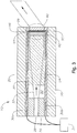
- FIGURES 3 and 4 illustrate another example of a system 10 that can electrically steer light in a laser probe according to certain embodiments.
- System 10 steers light by applying different voltages across different portions of beam steering cell 40.
- beam steering cell 40 includes cover plate 42, electrode layer 44 disposed outwardly from cover plate 42, OE element 46 disposed outwardly from electrode layer 44, electrode layer 90 disposed outwardly from OE element 46, and a cover plate 96.
- Electrode layers 44 and 90 apply different voltages across OE element 46.
- electrode layer 90 comprises strip electrodes 92, where at least two strip electrodes 92 apply different voltages.
- a strip electrode 92 may comprise any conductive material, such as ITO.
- strip electrodes 92 are individually addressable to yield monotonically changing voltage vs. position pattern.
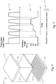
- FIGURES 5A through 5D illustrate an example of voltages applied to beam steering cell 40 of FIGURES 3 and 4 according to certain embodiments.
- the figures show how voltages may be applied to beam steering cell 40 with strip electrodes 92 to yield a monotonically changing refractive index versus position pattern.
- FIGURE 5A illustrates an example of a beam steering cell 40 with strip electrodes 92 and sides A and B.
- Different strip electrodes 92 may apply different voltages to yield a voltage vs. position pattern. Any suitable voltages may be applied.
- the voltages monotonically change with respect to position from side A to side B, e.g., from a voltage in a range of 10 to 250 volts at side A to a voltage in a range of 0 to 5 volts at side B.
- the voltage vs. position pattern yields a refractive index vs. position pattern.
- the refractive index monotonically changes with respect to position from side A to side B, e.g., from a refractive index in a range of 1.5 to 1.8 at side A to a refractive index in a range of 1.4 to 1.6 at side B. Accordingly, beam steering cell 40 may operate similarly to a wedge-shaped prism of FIGURE 5D .
- the time for a beam to pass through an optical element is inversely dependent on its optical thickness, which is product of the refractive index and thickness of cell 40 where the beam is traveling.
- the cell thickness is constant across the entire cell 40 and the refractive index varies across cell 40, so the optical thickness, and thus the beam transit time, varies monotonically across the cell.
- the refractive index is lower on the B side of the cell than the A side, so the beam passes through the B side of the cell faster than on the A side.
- incident and emitted beams are collimated.
- a collimated beam is normally incident on cell 40 of FIGURE 5A , the beam reaches an outer surface 98 of plate 96 on the B side more quickly than it does on the A side because the reflective index is lower on the B side than on the A side.
- the beam emerging from surface 98 should be planar, with the wavefront perpendicular to the beam direction.
- the same principle applies for the wedge prism, except in that case, the refractive index is constant and the prism thickness varies with lateral position. But the end result is the same: the planar striped LC cell has the same effect on incident light as a constant-index wedge prism.
- FIGURE 6 illustrates an example of a system 10 that can electrically steer light in two dimensions according to certain embodiments.
- Two or more beam steering cells 40 (40a-b) may be positioned in different directions to steer light beam 32 in two dimensions.
- two beam steering cells 40 may be position orthogonally such that cell 40a moves beam 32 along a first coordinate axis and cell 40b moves beam 32 along a second coordinate axis orthogonal to the first coordinate axis to allow for two-dimensional beam steering.
- FIGURE 7 illustrates an example of a pattern of diversion angles that may be used to yield a pattern of emitted light.
- the voltages applied to beam steering cell 40 may be changed to change divergence angle ⁇ .
- the changes in divergence angle ⁇ may yield a particular pattern of emitted light.
- graph 114 shows the pattern of emitted light resulting from the changes in divergence angle ⁇ .
- the laser power may be synchronized to be on when divergence angle ⁇ is at a desired angle ⁇ i , but off when divergence angle ⁇ transitioning between desired angles ⁇ i .
- the resulting light pattern may have clearer, less blurry, spots.
- the changes in voltage may be performed by a component that may include an interface, logic, memory, and/or other suitable element, any of which may include hardware and/or software.
- An interface can receive input, send output, process the input and/or output, and/or perform other suitable operations.
- Logic can perform the operations of a component, for example, execute instructions to generate output from input.
- Logic may be encoded in memory and may perform operations when executed by a computer.
- Logic may be a processor, such as one or more computers, one or more microprocessors, one or more applications, and/or other logic.
- a memory can store information and may comprise one or more tangible, computer-readable, and/or computer-executable storage medium.
- RAM Random Access Memory
- ROM Read Only Memory
- mass storage media for example, a hard disk
- removable storage media for example, a Compact Disk (CD) or a Digital Video Disk (DVD)
- database and/or network storage for example, a server
- network storage for example, a server
Landscapes
- Physics & Mathematics (AREA)
- Nonlinear Science (AREA)
- General Physics & Mathematics (AREA)
- Optics & Photonics (AREA)
- Chemical & Material Sciences (AREA)
- Dispersion Chemistry (AREA)
- Mathematical Physics (AREA)
- Crystallography & Structural Chemistry (AREA)
- Optical Modulation, Optical Deflection, Nonlinear Optics, Optical Demodulation, Optical Logic Elements (AREA)
- Liquid Crystal (AREA)
- Laser Surgery Devices (AREA)
- Mechanical Light Control Or Optical Switches (AREA)
Claims (10)
- System (10), welches umfasst:ein Gehäuse (20), das eine rohrförmige Gestalt, die einen inneren Bereich definiert, und wenigstens eine Öffnung aufweist;einen Lichtwellenleiter (28), der innerhalb des inneren Bereichs angeordnet ist, wobei der Lichtwellenleiter dafür ausgelegt ist, ein Lichtbündel (32) auszusenden, das in einer ersten Richtung verläuft; undeine Bündelsteuerungszelle (40), die innerhalb des Gehäuses angeordnet ist, wobei die Bündelsteuerungszelle ein elektrooptisches (EO) Element (46) umfasst, welches ein elektrooptisches Material aufweist, dessen Brechungsindex sich in Reaktion auf eine angelegte Spannung ändert, wobei die Bündelsteuerungszelle dafür ausgelegt ist:eine oder mehrere Spannungen zu empfangen; unddas Lichtbündel mit dem EO Material in Reaktion auf die eine oder die mehreren Spannungen elektrisch in eine zweite Richtung zu steuern, die von der ersten Richtung verschieden ist;dadurch gekennzeichnet, dass die Bündelsteuerungszelle (40) umfasst:eine erste Elektrodenschicht (44a);ein keilförmiges EO Element (46), welches das EO Material umfasst und außerhalb von der ersten Elektrodenschicht angeordnet ist;ein Prisma (48), das außerhalb von dem EO Element angeordnet ist, wobei ein optischer Weg durch das EO Element und das Prisma hindurch einen ersten Abschnitt (60a), der einen ersten EO Teil (64a) und einen ersten Prismateil (66a) umfasst, und einen zweiten Abschnitt (60b), der einen zweiten EO Teil (64b) und einen zweiten Prismateil (66b) umfasst, definiert, wobei der erste EO Teil größer als der zweite EO Teil ist; undeine zweite Elektrodenschicht (44b), die außerhalb von dem Prisma angeordnet ist.
- System nach Anspruch 1, wobei das Gehäuse (20) eine Kanüle umfasst.
- System nach Anspruch 1, wobei das EO Material ein Material aus polymereingebetteten Flüssigkristallen (Polymer-Dispersed Liquid Crystal, PDLC) umfasst.
- System nach Anspruch 1, wobei jede Elektrodenschicht (44a, 44b) ein optisch transparentes, elektrisch leitendes (Optically Transparent Electrically Conductive, OTEC) Material umfasst.
- System nach Anspruch 1, welches ferner umfasst:
eine Stromquelle (31), die dafür ausgelegt ist, die eine oder die mehreren Spannungen anzulegen. - System nach Anspruch 1, welches ferner umfasst:
eine Stromquelle (31), die dafür ausgelegt ist, die eine oder die mehreren Spannungen zu ändern, um den zweiten Winkel zu ändern, um ein Muster von ausgesendetem Licht zu erhalten. - System nach einem der Ansprüche 1 bis 6, welches umfasst:mehrere Bündelsteuerungszellen (40), die innerhalb des Gehäuses angeordnet sind, wobei eine erste Bündelsteuerungszelle orthogonal bezüglich einer zweiten Bündelsteuerungszelle angeordnet ist,wobei jede Bündelsteuerungszelle ein elektrooptisches (EO) Material umfasst, wobei jede Bündelsteuerungszelle dafür ausgelegt ist:eine oder mehrere Spannungen zu empfangen; unddas Lichtbündel mit dem EO Material in Reaktion auf die eine oder die mehreren Spannungen elektrisch in eine zweite Richtung zu steuern.
- Verfahren, welches umfasst:Aussenden, durch einen Lichtwellenleiter, der innerhalb eines inneren Bereichs eines Gehäuses angeordnet ist, eines Lichtbündels, das in einer ersten Richtung verläuft, wobei das Gehäuse eine rohrförmige Gestalt, die den inneren Bereich definiert, und wenigstens eine Öffnung aufweist;Empfangen, durch eine innerhalb des Gehäuses angeordnete Bündelsteuerungszelle, einer oder mehrerer Spannungen, wobei die Bündelsteuerungszelle (40) umfasst:eine erste Elektrodenschicht (44a);ein keilförmiges EO Element (46), welches das EO Material umfasst und außerhalb von der ersten Elektrodenschicht angeordnet ist;ein Prisma (48), das außerhalb von dem EO Element angeordnet ist, wobei ein optischer Weg durch das EO Element und das Prisma hindurch einen ersten Abschnitt (60a), der einen ersten EO Teil (64a) und einen ersten Prismateil (66a) umfasst, und einen zweiten Abschnitt (60b), der einen zweiten EO Teil (64b) und einen zweiten Prismateil (66b) umfasst, definiert, wobei der erste EO Teil größer als der zweite EO Teil ist; undeine zweite Elektrodenschicht (44b), die außerhalb von dem Prisma angeordnet ist;Empfangen, durch die Bündelsteuerungszelle, des Lichtbündels; undelektrisches Steuern des Lichtbündels mit dem EO Material in eine zweite Richtung in Reaktion auf die eine oder die mehreren Spannungen durch Anlegen der einen oder der mehreren Spannungen an das EO Element (46), wobei ein optischer Weg durch das EO Element hindurch einen ersten Abschnitt (60a), der einen ersten EO Teil (64a) umfasst, und einen zweiten Abschnitt (60b), der einen zweiten EO Teil (64b) umfasst, aufweist, wobei der erste EO Teil eine größere Dicke als der zweite EO Teil aufweist.
- Verfahren nach Anspruch 8, welches ferner umfasst:
Ändern der einen oder der mehreren Spannungen, um den zweiten Winkel zu ändern. - Verfahren nach Anspruch 8, welches ferner umfasst:
Ändern der einen oder der mehreren Spannungen, um den zweiten Winkel zu ändern, um ein Muster von ausgesendetem Licht zu erhalten.
Applications Claiming Priority (2)
| Application Number | Priority Date | Filing Date | Title |
|---|---|---|---|
| US13/226,675 US9086608B2 (en) | 2011-09-07 | 2011-09-07 | Laser probe with an electrically steerable light beam |
| PCT/US2012/043504 WO2013036314A2 (en) | 2011-09-07 | 2012-06-21 | Laser probe with an electrically steerable light beam |
Publications (3)
| Publication Number | Publication Date |
|---|---|
| EP2753975A2 EP2753975A2 (de) | 2014-07-16 |
| EP2753975A4 EP2753975A4 (de) | 2015-01-14 |
| EP2753975B1 true EP2753975B1 (de) | 2018-09-19 |
Family
ID=47752926
Family Applications (1)
| Application Number | Title | Priority Date | Filing Date |
|---|---|---|---|
| EP12830381.5A Not-in-force EP2753975B1 (de) | 2011-09-07 | 2012-06-21 | Lasersonde mit einem elektrisch verstellbaren lichtbündel |
Country Status (10)
| Country | Link |
|---|---|
| US (1) | US9086608B2 (de) |
| EP (1) | EP2753975B1 (de) |
| JP (1) | JP6185471B2 (de) |
| CN (1) | CN103930824A (de) |
| AU (1) | AU2012304914B2 (de) |
| BR (1) | BR112014005230A2 (de) |
| CA (1) | CA2845236C (de) |
| ES (1) | ES2702548T3 (de) |
| RU (1) | RU2608324C2 (de) |
| WO (1) | WO2013036314A2 (de) |
Families Citing this family (5)
| Publication number | Priority date | Publication date | Assignee | Title |
|---|---|---|---|---|
| US9849034B2 (en) | 2011-11-07 | 2017-12-26 | Alcon Research, Ltd. | Retinal laser surgery |
| US8939964B2 (en) * | 2011-12-01 | 2015-01-27 | Alcon Research, Ltd. | Electrically switchable multi-spot laser probe |
| US8888734B2 (en) | 2012-06-05 | 2014-11-18 | Alcon Research, Ltd. | Functionally graded material tube and method for use of the same in implantation |
| US9413461B2 (en) * | 2013-11-04 | 2016-08-09 | California Institute Of Technology | High bandwidth optical links for micro-satellite support |
| CN104932087A (zh) * | 2015-05-15 | 2015-09-23 | 奥普多威(开曼)控股有限公司 | 集成光学相干检测探头 |
Citations (2)
| Publication number | Priority date | Publication date | Assignee | Title |
|---|---|---|---|---|
| EP1105765A1 (de) * | 1998-08-19 | 2001-06-13 | Boston Scientific Limited | Optisches abtast - und abbildungssytem und verfahren |
| JP2003195274A (ja) * | 2001-12-28 | 2003-07-09 | Ricoh Co Ltd | 光偏向素子、光路切替デバイスおよび画像表示装置 |
Family Cites Families (20)
| Publication number | Priority date | Publication date | Assignee | Title |
|---|---|---|---|---|
| JPS61125337A (ja) * | 1984-11-21 | 1986-06-13 | オリンパス光学工業株式会社 | レ−ザ−メス装置 |
| US5363126A (en) * | 1992-09-25 | 1994-11-08 | Xerox Corporation | Device and apparatus for high speed tracking in a raster output scanner |
| US6821457B1 (en) * | 1998-07-29 | 2004-11-23 | Science Applications International Corporation | Electrically switchable polymer-dispersed liquid crystal materials including switchable optical couplers and reconfigurable optical interconnects |
| US6031658A (en) | 1998-09-25 | 2000-02-29 | University Of Central Florida | Digital control polarization based optical scanner |
| US6984230B2 (en) | 2000-04-07 | 2006-01-10 | Synergetics, Inc. | Directional laser probe |
| US6832028B2 (en) * | 2002-10-08 | 2004-12-14 | Innovative Technology Licensing, Llc | Liquid crystal adaptive coupler for steering a light beam relative to a light-receiving end of an optical waveguide |
| US6958851B2 (en) | 2003-12-03 | 2005-10-25 | Northrop Grumman Corporation | Electronically modulated prism |
| US8463080B1 (en) * | 2004-01-22 | 2013-06-11 | Vescent Photonics, Inc. | Liquid crystal waveguide having two or more control voltages for controlling polarized light |
| EP1612596A1 (de) | 2004-06-29 | 2006-01-04 | Fraunhofer-Gesellschaft zur Förderung der angewandten Forschung e.V. | Abstimmbare, schaltbare optische Elemente aus Flüssigkristallpolymerverbundwerkstoffen und Filmen, Mischungen und Verfahren zur deren Herstellung. |
| US7411724B2 (en) * | 2004-12-06 | 2008-08-12 | Northrop Grumman Corporation | Electro-optic crystal, diffraction-based, beam-steering element |
| US7400787B2 (en) | 2005-04-07 | 2008-07-15 | Photonic Systems, Inc. | Optical modulator with coupled coplanar strip electrode and domain inversion |
| US20070024978A1 (en) | 2005-08-01 | 2007-02-01 | Jackson John E | Conformal beam steering devices having a minimal volume and window area utilizing risley prisms and diffraction gratings |
| US10098781B2 (en) | 2006-03-24 | 2018-10-16 | Topcon Medical Laser Systems Inc. | Multi-spot optical fiber endophotocoagulation probe |
| US7566173B2 (en) | 2007-07-09 | 2009-07-28 | Alcon, Inc. | Multi-spot ophthalmic laser probe |
| WO2010104752A2 (en) | 2009-03-08 | 2010-09-16 | Oprobe, Llc | Multi-function optical probe system for medical and veterinary applications |
| JP5325640B2 (ja) * | 2009-04-08 | 2013-10-23 | オリンパス株式会社 | 内視鏡装置及びその光走査方法 |
| US8515217B2 (en) | 2009-09-02 | 2013-08-20 | Alcatel Lucent | Vertical optically emitting photonic devices with electronic steering capability |
| CN102655906B (zh) | 2009-12-15 | 2015-03-25 | 爱尔康研究有限公司 | 多点激光探针 |
| US20120075639A1 (en) * | 2010-09-24 | 2012-03-29 | Jeffrey Brennan | Imaging systems and methods incorporating non-mechanical scanning beam actuation |
| CN102207514B (zh) * | 2011-03-23 | 2013-07-17 | 吉林大学 | 一种基于流体电光材料的电光探头及用于探测电场的方法 |
-
2011
- 2011-09-07 US US13/226,675 patent/US9086608B2/en active Active
-
2012
- 2012-06-21 AU AU2012304914A patent/AU2012304914B2/en not_active Ceased
- 2012-06-21 ES ES12830381T patent/ES2702548T3/es active Active
- 2012-06-21 WO PCT/US2012/043504 patent/WO2013036314A2/en active Application Filing
- 2012-06-21 RU RU2014113388A patent/RU2608324C2/ru not_active IP Right Cessation
- 2012-06-21 EP EP12830381.5A patent/EP2753975B1/de not_active Not-in-force
- 2012-06-21 CN CN201280043495.5A patent/CN103930824A/zh active Pending
- 2012-06-21 JP JP2014529712A patent/JP6185471B2/ja not_active Expired - Fee Related
- 2012-06-21 BR BR112014005230A patent/BR112014005230A2/pt not_active Application Discontinuation
- 2012-06-21 CA CA2845236A patent/CA2845236C/en not_active Expired - Fee Related
Patent Citations (2)
| Publication number | Priority date | Publication date | Assignee | Title |
|---|---|---|---|---|
| EP1105765A1 (de) * | 1998-08-19 | 2001-06-13 | Boston Scientific Limited | Optisches abtast - und abbildungssytem und verfahren |
| JP2003195274A (ja) * | 2001-12-28 | 2003-07-09 | Ricoh Co Ltd | 光偏向素子、光路切替デバイスおよび画像表示装置 |
Also Published As
| Publication number | Publication date |
|---|---|
| BR112014005230A2 (pt) | 2017-04-11 |
| ES2702548T3 (es) | 2019-03-01 |
| CA2845236C (en) | 2019-08-20 |
| EP2753975A2 (de) | 2014-07-16 |
| US9086608B2 (en) | 2015-07-21 |
| CA2845236A1 (en) | 2013-03-14 |
| WO2013036314A3 (en) | 2014-05-01 |
| CN103930824A (zh) | 2014-07-16 |
| WO2013036314A2 (en) | 2013-03-14 |
| RU2014113388A (ru) | 2015-10-20 |
| RU2608324C2 (ru) | 2017-01-17 |
| US20130057821A1 (en) | 2013-03-07 |
| JP2014529103A (ja) | 2014-10-30 |
| EP2753975A4 (de) | 2015-01-14 |
| JP6185471B2 (ja) | 2017-08-23 |
| AU2012304914B2 (en) | 2015-07-02 |
| AU2012304914A1 (en) | 2014-03-06 |
Similar Documents
| Publication | Publication Date | Title |
|---|---|---|
| US9910338B2 (en) | Electrically switchable multi-spot laser probe | |
| EP2753975B1 (de) | Lasersonde mit einem elektrisch verstellbaren lichtbündel | |
| US7324287B1 (en) | Multi-fluid lenses and optical devices incorporating the same | |
| KR102411662B1 (ko) | 액정 광 편향기 및 액정 광 편향기를 구비한 홀로그래픽 디스플레이 | |
| US20210116776A1 (en) | Liquid crystal mixtures for pitch variable optical elements | |
| US9411103B2 (en) | Contact focusing hollow-core fiber microprobes | |
| US20140194750A1 (en) | Optical zoom probe | |
| KR102607856B1 (ko) | 2차원 빔 스티어링 소자 | |
| US20220397791A1 (en) | Optical layer and optical system | |
| KR102208740B1 (ko) | 플라즈모닉스를 이용한 빔 스티어링 장치 | |
| US9335572B2 (en) | Image display apparatus | |
| US11156816B2 (en) | Reflective spatial light modulator having non-conducting adhesive material, optical observation device and optical irradiation device | |
| TWI727542B (zh) | 電濕潤控制光學掃描探頭 | |
| US11236885B1 (en) | Switchable flood and spot illuminator | |
| KR20220058285A (ko) | 빔 편향기 및 이를 포함하는 3차원 디스플레이 장치 | |
| KR20230004260A (ko) | 레이저 가공 장치 및 레이저 가공 방법 | |
| JPH01100506A (ja) | 光ファイバ結合器 |
Legal Events
| Date | Code | Title | Description |
|---|---|---|---|
| PUAI | Public reference made under article 153(3) epc to a published international application that has entered the european phase |
Free format text: ORIGINAL CODE: 0009012 |
|
| 17P | Request for examination filed |
Effective date: 20140213 |
|
| AK | Designated contracting states |
Kind code of ref document: A2 Designated state(s): AL AT BE BG CH CY CZ DE DK EE ES FI FR GB GR HR HU IE IS IT LI LT LU LV MC MK MT NL NO PL PT RO RS SE SI SK SM TR |
|
| A4 | Supplementary search report drawn up and despatched |
Effective date: 20141215 |
|
| RIC1 | Information provided on ipc code assigned before grant |
Ipc: G02F 1/035 20060101ALI20141209BHEP Ipc: G02F 1/03 20060101AFI20141209BHEP |
|
| DAX | Request for extension of the european patent (deleted) | ||
| 17Q | First examination report despatched |
Effective date: 20160922 |
|
| STAA | Information on the status of an ep patent application or granted ep patent |
Free format text: STATUS: EXAMINATION IS IN PROGRESS |
|
| GRAP | Despatch of communication of intention to grant a patent |
Free format text: ORIGINAL CODE: EPIDOSNIGR1 |
|
| STAA | Information on the status of an ep patent application or granted ep patent |
Free format text: STATUS: GRANT OF PATENT IS INTENDED |
|
| INTG | Intention to grant announced |
Effective date: 20180515 |
|
| GRAS | Grant fee paid |
Free format text: ORIGINAL CODE: EPIDOSNIGR3 |
|
| GRAA | (expected) grant |
Free format text: ORIGINAL CODE: 0009210 |
|
| STAA | Information on the status of an ep patent application or granted ep patent |
Free format text: STATUS: THE PATENT HAS BEEN GRANTED |
|
| AK | Designated contracting states |
Kind code of ref document: B1 Designated state(s): AL AT BE BG CH CY CZ DE DK EE ES FI FR GB GR HR HU IE IS IT LI LT LU LV MC MK MT NL NO PL PT RO RS SE SI SK SM TR |
|
| REG | Reference to a national code |
Ref country code: GB Ref legal event code: FG4D |
|
| REG | Reference to a national code |
Ref country code: CH Ref legal event code: EP |
|
| REG | Reference to a national code |
Ref country code: AT Ref legal event code: REF Ref document number: 1043927 Country of ref document: AT Kind code of ref document: T Effective date: 20181015 |
|
| REG | Reference to a national code |
Ref country code: IE Ref legal event code: FG4D |
|
| REG | Reference to a national code |
Ref country code: DE Ref legal event code: R096 Ref document number: 602012051374 Country of ref document: DE |
|
| REG | Reference to a national code |
Ref country code: NL Ref legal event code: MP Effective date: 20180919 |
|
| PG25 | Lapsed in a contracting state [announced via postgrant information from national office to epo] |
Ref country code: NO Free format text: LAPSE BECAUSE OF FAILURE TO SUBMIT A TRANSLATION OF THE DESCRIPTION OR TO PAY THE FEE WITHIN THE PRESCRIBED TIME-LIMIT Effective date: 20181219 Ref country code: LT Free format text: LAPSE BECAUSE OF FAILURE TO SUBMIT A TRANSLATION OF THE DESCRIPTION OR TO PAY THE FEE WITHIN THE PRESCRIBED TIME-LIMIT Effective date: 20180919 Ref country code: BG Free format text: LAPSE BECAUSE OF FAILURE TO SUBMIT A TRANSLATION OF THE DESCRIPTION OR TO PAY THE FEE WITHIN THE PRESCRIBED TIME-LIMIT Effective date: 20181219 Ref country code: FI Free format text: LAPSE BECAUSE OF FAILURE TO SUBMIT A TRANSLATION OF THE DESCRIPTION OR TO PAY THE FEE WITHIN THE PRESCRIBED TIME-LIMIT Effective date: 20180919 Ref country code: GR Free format text: LAPSE BECAUSE OF FAILURE TO SUBMIT A TRANSLATION OF THE DESCRIPTION OR TO PAY THE FEE WITHIN THE PRESCRIBED TIME-LIMIT Effective date: 20181220 Ref country code: RS Free format text: LAPSE BECAUSE OF FAILURE TO SUBMIT A TRANSLATION OF THE DESCRIPTION OR TO PAY THE FEE WITHIN THE PRESCRIBED TIME-LIMIT Effective date: 20180919 Ref country code: SE Free format text: LAPSE BECAUSE OF FAILURE TO SUBMIT A TRANSLATION OF THE DESCRIPTION OR TO PAY THE FEE WITHIN THE PRESCRIBED TIME-LIMIT Effective date: 20180919 |
|
| REG | Reference to a national code |
Ref country code: LT Ref legal event code: MG4D |
|
| PG25 | Lapsed in a contracting state [announced via postgrant information from national office to epo] |
Ref country code: AL Free format text: LAPSE BECAUSE OF FAILURE TO SUBMIT A TRANSLATION OF THE DESCRIPTION OR TO PAY THE FEE WITHIN THE PRESCRIBED TIME-LIMIT Effective date: 20180919 Ref country code: LV Free format text: LAPSE BECAUSE OF FAILURE TO SUBMIT A TRANSLATION OF THE DESCRIPTION OR TO PAY THE FEE WITHIN THE PRESCRIBED TIME-LIMIT Effective date: 20180919 Ref country code: HR Free format text: LAPSE BECAUSE OF FAILURE TO SUBMIT A TRANSLATION OF THE DESCRIPTION OR TO PAY THE FEE WITHIN THE PRESCRIBED TIME-LIMIT Effective date: 20180919 |
|
| REG | Reference to a national code |
Ref country code: ES Ref legal event code: FG2A Ref document number: 2702548 Country of ref document: ES Kind code of ref document: T3 Effective date: 20190301 |
|
| REG | Reference to a national code |
Ref country code: AT Ref legal event code: MK05 Ref document number: 1043927 Country of ref document: AT Kind code of ref document: T Effective date: 20180919 |
|
| PG25 | Lapsed in a contracting state [announced via postgrant information from national office to epo] |
Ref country code: PL Free format text: LAPSE BECAUSE OF FAILURE TO SUBMIT A TRANSLATION OF THE DESCRIPTION OR TO PAY THE FEE WITHIN THE PRESCRIBED TIME-LIMIT Effective date: 20180919 Ref country code: EE Free format text: LAPSE BECAUSE OF FAILURE TO SUBMIT A TRANSLATION OF THE DESCRIPTION OR TO PAY THE FEE WITHIN THE PRESCRIBED TIME-LIMIT Effective date: 20180919 Ref country code: AT Free format text: LAPSE BECAUSE OF FAILURE TO SUBMIT A TRANSLATION OF THE DESCRIPTION OR TO PAY THE FEE WITHIN THE PRESCRIBED TIME-LIMIT Effective date: 20180919 Ref country code: IS Free format text: LAPSE BECAUSE OF FAILURE TO SUBMIT A TRANSLATION OF THE DESCRIPTION OR TO PAY THE FEE WITHIN THE PRESCRIBED TIME-LIMIT Effective date: 20190119 Ref country code: RO Free format text: LAPSE BECAUSE OF FAILURE TO SUBMIT A TRANSLATION OF THE DESCRIPTION OR TO PAY THE FEE WITHIN THE PRESCRIBED TIME-LIMIT Effective date: 20180919 Ref country code: NL Free format text: LAPSE BECAUSE OF FAILURE TO SUBMIT A TRANSLATION OF THE DESCRIPTION OR TO PAY THE FEE WITHIN THE PRESCRIBED TIME-LIMIT Effective date: 20180919 Ref country code: CZ Free format text: LAPSE BECAUSE OF FAILURE TO SUBMIT A TRANSLATION OF THE DESCRIPTION OR TO PAY THE FEE WITHIN THE PRESCRIBED TIME-LIMIT Effective date: 20180919 |
|
| PG25 | Lapsed in a contracting state [announced via postgrant information from national office to epo] |
Ref country code: SK Free format text: LAPSE BECAUSE OF FAILURE TO SUBMIT A TRANSLATION OF THE DESCRIPTION OR TO PAY THE FEE WITHIN THE PRESCRIBED TIME-LIMIT Effective date: 20180919 Ref country code: PT Free format text: LAPSE BECAUSE OF FAILURE TO SUBMIT A TRANSLATION OF THE DESCRIPTION OR TO PAY THE FEE WITHIN THE PRESCRIBED TIME-LIMIT Effective date: 20190119 Ref country code: SM Free format text: LAPSE BECAUSE OF FAILURE TO SUBMIT A TRANSLATION OF THE DESCRIPTION OR TO PAY THE FEE WITHIN THE PRESCRIBED TIME-LIMIT Effective date: 20180919 |
|
| REG | Reference to a national code |
Ref country code: DE Ref legal event code: R097 Ref document number: 602012051374 Country of ref document: DE |
|
| PLBE | No opposition filed within time limit |
Free format text: ORIGINAL CODE: 0009261 |
|
| STAA | Information on the status of an ep patent application or granted ep patent |
Free format text: STATUS: NO OPPOSITION FILED WITHIN TIME LIMIT |
|
| PG25 | Lapsed in a contracting state [announced via postgrant information from national office to epo] |
Ref country code: DK Free format text: LAPSE BECAUSE OF FAILURE TO SUBMIT A TRANSLATION OF THE DESCRIPTION OR TO PAY THE FEE WITHIN THE PRESCRIBED TIME-LIMIT Effective date: 20180919 |
|
| PGFP | Annual fee paid to national office [announced via postgrant information from national office to epo] |
Ref country code: IT Payment date: 20190620 Year of fee payment: 8 Ref country code: DE Payment date: 20190612 Year of fee payment: 8 |
|
| 26N | No opposition filed |
Effective date: 20190620 |
|
| PGFP | Annual fee paid to national office [announced via postgrant information from national office to epo] |
Ref country code: FR Payment date: 20190604 Year of fee payment: 8 |
|
| PG25 | Lapsed in a contracting state [announced via postgrant information from national office to epo] |
Ref country code: SI Free format text: LAPSE BECAUSE OF FAILURE TO SUBMIT A TRANSLATION OF THE DESCRIPTION OR TO PAY THE FEE WITHIN THE PRESCRIBED TIME-LIMIT Effective date: 20180919 |
|
| PGFP | Annual fee paid to national office [announced via postgrant information from national office to epo] |
Ref country code: GB Payment date: 20190619 Year of fee payment: 8 Ref country code: ES Payment date: 20190701 Year of fee payment: 8 |
|
| PG25 | Lapsed in a contracting state [announced via postgrant information from national office to epo] |
Ref country code: MC Free format text: LAPSE BECAUSE OF FAILURE TO SUBMIT A TRANSLATION OF THE DESCRIPTION OR TO PAY THE FEE WITHIN THE PRESCRIBED TIME-LIMIT Effective date: 20180919 |
|
| REG | Reference to a national code |
Ref country code: CH Ref legal event code: PL |
|
| REG | Reference to a national code |
Ref country code: GB Ref legal event code: 732E Free format text: REGISTERED BETWEEN 20200109 AND 20200115 |
|
| REG | Reference to a national code |
Ref country code: GB Ref legal event code: 732E Free format text: REGISTERED BETWEEN 20200116 AND 20200122 |
|
| REG | Reference to a national code |
Ref country code: DE Ref legal event code: R081 Ref document number: 602012051374 Country of ref document: DE Owner name: ALCON INC., CH Free format text: FORMER OWNER: ALCON RESEARCH, LTD., FORT WORTH, TEX., US |
|
| REG | Reference to a national code |
Ref country code: BE Ref legal event code: MM Effective date: 20190630 |
|
| PG25 | Lapsed in a contracting state [announced via postgrant information from national office to epo] |
Ref country code: TR Free format text: LAPSE BECAUSE OF FAILURE TO SUBMIT A TRANSLATION OF THE DESCRIPTION OR TO PAY THE FEE WITHIN THE PRESCRIBED TIME-LIMIT Effective date: 20180919 |
|
| REG | Reference to a national code |
Ref country code: ES Ref legal event code: PC2A Owner name: ALCON INC. Effective date: 20200407 |
|
| PG25 | Lapsed in a contracting state [announced via postgrant information from national office to epo] |
Ref country code: IE Free format text: LAPSE BECAUSE OF NON-PAYMENT OF DUE FEES Effective date: 20190621 |
|
| PG25 | Lapsed in a contracting state [announced via postgrant information from national office to epo] |
Ref country code: LI Free format text: LAPSE BECAUSE OF NON-PAYMENT OF DUE FEES Effective date: 20190630 Ref country code: LU Free format text: LAPSE BECAUSE OF NON-PAYMENT OF DUE FEES Effective date: 20190621 Ref country code: BE Free format text: LAPSE BECAUSE OF NON-PAYMENT OF DUE FEES Effective date: 20190630 Ref country code: CH Free format text: LAPSE BECAUSE OF NON-PAYMENT OF DUE FEES Effective date: 20190630 |
|
| REG | Reference to a national code |
Ref country code: DE Ref legal event code: R119 Ref document number: 602012051374 Country of ref document: DE |
|
| GBPC | Gb: european patent ceased through non-payment of renewal fee |
Effective date: 20200621 |
|
| PG25 | Lapsed in a contracting state [announced via postgrant information from national office to epo] |
Ref country code: FR Free format text: LAPSE BECAUSE OF NON-PAYMENT OF DUE FEES Effective date: 20200630 Ref country code: GB Free format text: LAPSE BECAUSE OF NON-PAYMENT OF DUE FEES Effective date: 20200621 |
|
| PG25 | Lapsed in a contracting state [announced via postgrant information from national office to epo] |
Ref country code: CY Free format text: LAPSE BECAUSE OF FAILURE TO SUBMIT A TRANSLATION OF THE DESCRIPTION OR TO PAY THE FEE WITHIN THE PRESCRIBED TIME-LIMIT Effective date: 20180919 Ref country code: DE Free format text: LAPSE BECAUSE OF NON-PAYMENT OF DUE FEES Effective date: 20210101 |
|
| PG25 | Lapsed in a contracting state [announced via postgrant information from national office to epo] |
Ref country code: HU Free format text: LAPSE BECAUSE OF FAILURE TO SUBMIT A TRANSLATION OF THE DESCRIPTION OR TO PAY THE FEE WITHIN THE PRESCRIBED TIME-LIMIT; INVALID AB INITIO Effective date: 20120621 Ref country code: MT Free format text: LAPSE BECAUSE OF FAILURE TO SUBMIT A TRANSLATION OF THE DESCRIPTION OR TO PAY THE FEE WITHIN THE PRESCRIBED TIME-LIMIT Effective date: 20180919 |
|
| PG25 | Lapsed in a contracting state [announced via postgrant information from national office to epo] |
Ref country code: IT Free format text: LAPSE BECAUSE OF NON-PAYMENT OF DUE FEES Effective date: 20200621 |
|
| PG25 | Lapsed in a contracting state [announced via postgrant information from national office to epo] |
Ref country code: ES Free format text: LAPSE BECAUSE OF NON-PAYMENT OF DUE FEES Effective date: 20200622 |
|
| PG25 | Lapsed in a contracting state [announced via postgrant information from national office to epo] |
Ref country code: MK Free format text: LAPSE BECAUSE OF FAILURE TO SUBMIT A TRANSLATION OF THE DESCRIPTION OR TO PAY THE FEE WITHIN THE PRESCRIBED TIME-LIMIT Effective date: 20180919 |