EP2753871B1 - Lighting device and lighting control method - Google Patents
Lighting device and lighting control method Download PDFInfo
- Publication number
- EP2753871B1 EP2753871B1 EP12829863.5A EP12829863A EP2753871B1 EP 2753871 B1 EP2753871 B1 EP 2753871B1 EP 12829863 A EP12829863 A EP 12829863A EP 2753871 B1 EP2753871 B1 EP 2753871B1
- Authority
- EP
- European Patent Office
- Prior art keywords
- light emitting
- emitting devices
- emitting device
- white light
- disposed
- Prior art date
- Legal status (The legal status is an assumption and is not a legal conclusion. Google has not performed a legal analysis and makes no representation as to the accuracy of the status listed.)
- Active
Links
- 238000000034 method Methods 0.000 title claims description 35
- 230000003287 optical effect Effects 0.000 claims description 62
- 239000000758 substrate Substances 0.000 claims description 49
- 230000005284 excitation Effects 0.000 claims description 46
- 238000010586 diagram Methods 0.000 claims description 41
- 230000005457 Black-body radiation Effects 0.000 claims description 35
- 239000000203 mixture Substances 0.000 claims description 31
- 150000001875 compounds Chemical class 0.000 claims description 4
- 239000003822 epoxy resin Substances 0.000 claims description 4
- 229920000647 polyepoxide Polymers 0.000 claims description 4
- 229920002050 silicone resin Polymers 0.000 claims description 4
- 229920002803 thermoplastic polyurethane Polymers 0.000 claims description 4
- OAICVXFJPJFONN-UHFFFAOYSA-N Phosphorus Chemical compound [P] OAICVXFJPJFONN-UHFFFAOYSA-N 0.000 description 72
- 230000001276 controlling effect Effects 0.000 description 11
- 230000004044 response Effects 0.000 description 11
- BPQQTUXANYXVAA-UHFFFAOYSA-N Orthosilicate Chemical compound [O-][Si]([O-])([O-])[O-] BPQQTUXANYXVAA-UHFFFAOYSA-N 0.000 description 7
- 238000013461 design Methods 0.000 description 7
- 239000002223 garnet Substances 0.000 description 7
- 229910019655 synthetic inorganic crystalline material Inorganic materials 0.000 description 7
- 230000004907 flux Effects 0.000 description 6
- 239000000463 material Substances 0.000 description 5
- 238000009877 rendering Methods 0.000 description 4
- 230000003247 decreasing effect Effects 0.000 description 3
- 238000004088 simulation Methods 0.000 description 3
- 229910003564 SiAlON Inorganic materials 0.000 description 2
- 238000002474 experimental method Methods 0.000 description 2
- 238000004519 manufacturing process Methods 0.000 description 2
- 150000004767 nitrides Chemical class 0.000 description 2
- 230000005855 radiation Effects 0.000 description 2
- 229920005989 resin Polymers 0.000 description 2
- 239000011347 resin Substances 0.000 description 2
- 239000000126 substance Substances 0.000 description 2
- UCKMPCXJQFINFW-UHFFFAOYSA-N Sulphide Chemical compound [S-2] UCKMPCXJQFINFW-UHFFFAOYSA-N 0.000 description 1
- 239000002390 adhesive tape Substances 0.000 description 1
- 229910052782 aluminium Inorganic materials 0.000 description 1
- 230000015556 catabolic process Effects 0.000 description 1
- 229910019990 cerium-doped yttrium aluminum garnet Inorganic materials 0.000 description 1
- 239000003086 colorant Substances 0.000 description 1
- 229910052802 copper Inorganic materials 0.000 description 1
- 230000002596 correlated effect Effects 0.000 description 1
- 238000006731 degradation reaction Methods 0.000 description 1
- 239000002019 doping agent Substances 0.000 description 1
- 230000000694 effects Effects 0.000 description 1
- 230000003760 hair shine Effects 0.000 description 1
- 229910052909 inorganic silicate Inorganic materials 0.000 description 1
- 239000002184 metal Substances 0.000 description 1
- 229910052751 metal Inorganic materials 0.000 description 1
- 239000007769 metal material Substances 0.000 description 1
- 229910052759 nickel Inorganic materials 0.000 description 1
- 238000011160 research Methods 0.000 description 1
- 230000032554 response to blue light Effects 0.000 description 1
- 229910052709 silver Inorganic materials 0.000 description 1
- 239000002904 solvent Substances 0.000 description 1
- 238000001228 spectrum Methods 0.000 description 1
- 229910052718 tin Inorganic materials 0.000 description 1
- 238000012546 transfer Methods 0.000 description 1
Images


Classifications
-
- H—ELECTRICITY
- H05—ELECTRIC TECHNIQUES NOT OTHERWISE PROVIDED FOR
- H05B—ELECTRIC HEATING; ELECTRIC LIGHT SOURCES NOT OTHERWISE PROVIDED FOR; CIRCUIT ARRANGEMENTS FOR ELECTRIC LIGHT SOURCES, IN GENERAL
- H05B45/00—Circuit arrangements for operating light-emitting diodes [LED]
- H05B45/20—Controlling the colour of the light
-
- F—MECHANICAL ENGINEERING; LIGHTING; HEATING; WEAPONS; BLASTING
- F21—LIGHTING
- F21K—NON-ELECTRIC LIGHT SOURCES USING LUMINESCENCE; LIGHT SOURCES USING ELECTROCHEMILUMINESCENCE; LIGHT SOURCES USING CHARGES OF COMBUSTIBLE MATERIAL; LIGHT SOURCES USING SEMICONDUCTOR DEVICES AS LIGHT-GENERATING ELEMENTS; LIGHT SOURCES NOT OTHERWISE PROVIDED FOR
- F21K9/00—Light sources using semiconductor devices as light-generating elements, e.g. using light-emitting diodes [LED] or lasers
- F21K9/60—Optical arrangements integrated in the light source, e.g. for improving the colour rendering index or the light extraction
- F21K9/62—Optical arrangements integrated in the light source, e.g. for improving the colour rendering index or the light extraction using mixing chambers, e.g. housings with reflective walls
-
- F—MECHANICAL ENGINEERING; LIGHTING; HEATING; WEAPONS; BLASTING
- F21—LIGHTING
- F21K—NON-ELECTRIC LIGHT SOURCES USING LUMINESCENCE; LIGHT SOURCES USING ELECTROCHEMILUMINESCENCE; LIGHT SOURCES USING CHARGES OF COMBUSTIBLE MATERIAL; LIGHT SOURCES USING SEMICONDUCTOR DEVICES AS LIGHT-GENERATING ELEMENTS; LIGHT SOURCES NOT OTHERWISE PROVIDED FOR
- F21K9/00—Light sources using semiconductor devices as light-generating elements, e.g. using light-emitting diodes [LED] or lasers
- F21K9/60—Optical arrangements integrated in the light source, e.g. for improving the colour rendering index or the light extraction
- F21K9/64—Optical arrangements integrated in the light source, e.g. for improving the colour rendering index or the light extraction using wavelength conversion means distinct or spaced from the light-generating element, e.g. a remote phosphor layer
-
- H—ELECTRICITY
- H05—ELECTRIC TECHNIQUES NOT OTHERWISE PROVIDED FOR
- H05B—ELECTRIC HEATING; ELECTRIC LIGHT SOURCES NOT OTHERWISE PROVIDED FOR; CIRCUIT ARRANGEMENTS FOR ELECTRIC LIGHT SOURCES, IN GENERAL
- H05B45/00—Circuit arrangements for operating light-emitting diodes [LED]
- H05B45/20—Controlling the colour of the light
- H05B45/24—Controlling the colour of the light using electrical feedback from LEDs or from LED modules
-
- F—MECHANICAL ENGINEERING; LIGHTING; HEATING; WEAPONS; BLASTING
- F21—LIGHTING
- F21Y—INDEXING SCHEME ASSOCIATED WITH SUBCLASSES F21K, F21L, F21S and F21V, RELATING TO THE FORM OR THE KIND OF THE LIGHT SOURCES OR OF THE COLOUR OF THE LIGHT EMITTED
- F21Y2113/00—Combination of light sources
- F21Y2113/10—Combination of light sources of different colours
- F21Y2113/13—Combination of light sources of different colours comprising an assembly of point-like light sources
Description
- This embodiment relates to a lighting device and a lighting control method.
-
EP 2211083 A1 is considered the closest prior art and shows all of the features of the preamble of claim 1. - A white light emitting device is now increasingly used in, for example, an LCD backlight unit, a camera phone flash, an electric sign, a lighting device and the like. Therefore, many researches are now being actively devoted to the white light emitting device.
- A method for manufacturing the white light emitting device includes a method using a single chip and a method using multi-chips. The method using a single chip is to obtain white light by adding a phosphor on a blue LED chip or an UV LED chip. The method using multi-chips is to obtain white light by combining two or three LED chips emitting lights having mutually different wavelengths.
- One of the methods using multi-chips is to create white light by combining three R, G and B LED chips. However, an operating voltage of each of the LED chips is not uniform and the output of each of the LED chips is changed according to an ambient temperature, so that the color coordinate of the LED chip is changed. Therefore, generally, the white light emitting device is easily and efficiently manufactured by the method using a single chip. For example, a white LED is manufactured by combining a blue LED and a phosphor which is excited by the blue LED and emitsyellow light. Also, the white light is created by mixing UV LED light and light which has multiple wavelengths and is excited by the UV LED. Here, UV light is wholly used to excite the phosphor and does not contribute directly to the generation of the white light.
- Meanwhile, an indicator for analyzing the characteristic of white light includes a correlated color temperature (CCT)and a color rendering index (CRI). Regarding an object emits visible light and shines, when the color of the object is the same as a color thata certain temperature black body radiates, the temperature of the black body and the temperature of the object are considered to be the same as each other. Here, the CCT represents the temperature. Since the color of white light having a low color temperature seems to be warmer and the color of white light having a high color temperature seems to be colder, it is possible to create various color senses by controlling the color temperature.
- When sunlight is irradiated to an object and artificial lighting isirradiated, the color of the object is changed. Here, the CRI represents how much the color of the object is changed. When the color of the object is the same as the color under sunlight,the CRI is defined to be 100. That is, the CRI represents how similar the color of the object under the artificial lighting is to the color of the object under sunlight. The CRI has values from 0 to 100. The closer the CRI of a white light source is to 100, the light from the white light source seems to be more similar to sunlight. While the CRI of an incandescent bulb is greater than 80 and the CRI of a fluorescent lamp is greater than 75, the CRI of a commercially used white LED is approximately 70 to 75.
- Therefore, there is a requirement that white light should be seem to be similar to natural light by improving color rendering property.
- The objective of the present invention is to provide a lighting device and a lighting control method which cause the color coordinate of light emitted a white light emitting device to be located on a black body radiation curve within a 1931 CIE chromaticity diagram, and then provide white light similar to natural light. As a result, optical efficiency and color rendering property can be more improved.
- One example is a lighting device. The lighting device includes: a first to a fourth light emitting devices which are disposed on a substrate a first and a second pulse width modulation controllers which perform a pulse width modulation on currents applied to the first and the second light emitting devices respectively; and a first and a second controllers which control respectively currents applied to the third and the fourth light emitting devices having color temperatures different from those of the first and the second light emitting devices. An (x, y) coordinate, which is determined by the mixture of the lights emitted from the first to the fourth light emitting devices and is located within a 1931 CIE chromaticity diagram, is moved onto a black body radiation curve within the 1931 CIE chromaticity diagram through the pulse width modulation of the first and the second pulse width modulation controllers and the control of the first and the second controllers.
- The first light emitting device, the second light emitting device, the third light emitting device and the fourth light emitting devices are disposed in the form of a linear array in the order listed.
- Color temperatures of the first and the third light emitting devices are higher than those of the second and the fourth light emitting devices.
- The lighting device further includes a mixing chamber which receives the first to the fourth light emitting devices and has an open upper portion; and an optical excitation plate which is disposed on the mixing chamber and is spaced apart from the first to the fourth light emitting devices.
- A distance between the optical excitation plate and the first to the fourth light emitting devices is determined by an optical orientation angle of each of the light emitting devices and a distance between the light emitting devices.
- When a distance between the first to the fourth light emitting devices and the optical excitation plate is "H" and the optical orientation angle of each of the light emitting devices is "θ", the distance G between the light emitting devices is calculated by an equation of G = 2Htan(θ/2).
- A distance "L"between an inner wall of the mixing chamber and a light emitting device located at the outermost among the first to the fourth light emitting devices is calculated by an equation of L≥G/2.
- When a plurality of the light emitting devices are symmetrically disposed, the distance "G" between the light emitting devices is minimized.
- The distance "H" between the first to the fourth light emitting devices and the optical excitation plate is determined within a range in which lights generated from each of the light emitting devices are not superposed on each other or are superposed on each other by less than 10 %.
- The distance "G" between the light emitting devices is between 25 mm and 30 mm.
- Both inner walls of the mixing chamber are equally vertical or equally inclined.
- The lighting device further includes a reflector which is disposed to have the same inclined surfaces on both inner walls of the mixing chamber.
- The lighting device further includes a lens unit which is disposed on the optical excitation plate and adjusts an orientation angle of the light.
- The lens unit has any one of a concave shape, a convex shape and a hemispherical shape and is formed of any one of an epoxy resin, a silicone resin, a urethane resin or a compound of them.
- Another example is a lighting device. The lighting device includes: a first white light emitting device which includes a first light emitting chip disposed on a substrate and a first phosphor converting first light emitted from the first light emitting chip; a second white light emitting device which includes a second light emitting chip disposed on the substrate and a second phosphor converting second light emitted from the second light emitting chip; and a red light emitting device which is disposed on the substrate and emits red light. An (x, y) coordinate, which is determined by the mixture of the lights emitted from the first and the second white light emitting devices and the red light emitting device and is located within a 1931 CIE chromaticity diagram, is moved onto a black body radiation curve within the 1931 CIE chromaticity diagram by wavelength deviations of 1 nm to 70 nm of the first and the second lights.
- Further another example is a lighting device. The lighting device includes: a light source which includes a first light emitting device emitting first light, a second light emitting device emitting second light, and a red light emitting device emitting red light, wherein the first light emitting device, the second light emitting device and the red light emitting device are disposed on a substrate; and an optical excitation plate which is disposed on the light source and is disposed apart at a predetermined interval from the first light emitting device, the second light emitting device and the red light emitting device, and includes a yellow phosphor. An (x, y) coordinate, which is determined by the mixture of the lights emitted from the first and the second light emitting devices and the red light emitting device and is located within a 1931 CIE chromaticity diagram, is moved onto a black body radiation curve within the 1931 CIE chromaticity diagram by wavelength deviations of 1 nm to 70 nm of the first and the second lights.
- The first and the second lights have a wavelength of from 420 nm to 490 nm.
- The larger the deviations of the wavelengths of the first and the second lights become, the smaller the magnitudes of currents applied to the first and the second white light emitting devices, so that a color of the emitted light is changed.
- The larger the deviations of the wavelengths of the first and the second lights become, the smaller the magnitudes of currents applied to the first and the second light emitting devices, so that a color of the emitted light is changed.
- The substrate includes a first substrate and a second substrate disposed apart from the first substrate. The first white light emitting device is disposed on the first substrate. The second white light emitting device is disposed on the second substrate. The phosphor is a garnet (including YAG) phosphor or an oxynitride phosphor
- A distance between the optical excitation plate and each of the light emitting devices of the light source is determined by an optical orientation angle of each of the light emitting devices and a distance between the light emitting devices.
- When a distance between the first and the second light emitting devices and the red light emitting device and the optical excitation plate is "H" and the optical orientation angle of each of the light emitting devices is "θ", the distance G between the light emitting devices is calculated by an equation of G = 2Htan(θ/2).
- The lighting device further includes a mixing chamber which receives the light source and has an open upper portion.
- A distance "L" between an inner wall of the mixing chamber and a light emitting device located at the outermost among the light emitting devices of the light source is calculated by an equation of L≥G/2.
- When a plurality of the light emitting devices are symmetrically disposed, the distance "G" between the light emitting devices is minimized.
- The distance "H" between each of the light emitting devices of the light source and the optical excitation plate is determined within a range in which lights generated from each of the light emitting devices are not superposed on each other or are superposed on each other by less than 10 %.
- The distance "G" between the light emitting devices is between 25 mm and 30 mm.
- Both inner walls of the mixing chamber are equally vertical or equally inclined.
- The lighting device further includes a reflector which is disposed to have the same inclined surfaces on both inner walls of the mixing chamber.
- The lighting device further includes a lens unit which is disposed on the optical excitation plate and adjusts an orientation angle of the light.
- The lens unit has any one of a concave shape, a convex shape and a hemispherical shape and is formed of any one of an epoxy resin, a silicone resin, a urethane resin or a compound of them.
- Yet another embodiment is a lighting control method. The method includes: a first step of applying first set current and second set current to a first and a second light emitting devices respectively, and of obtaining a (x, y) coordinate which is determined by the mixture of the lights emitted from the first and the second light emitting devices and is located within a 1931 CIE chromaticity diagram a second step of respectively applying third set current and fourth set current to a third and a fourth light emitting devices having color temperatures different from thoseof the first and the second light emitting devices, and of obtaining a (x, y) coordinate which is determined by the mixture of the lights emitted from the first to the fourth light emitting devices and is located within the 1931 CIE chromaticity diagram and a third step of pulse-width modulating the current applied to at least one of the first and the second light emitting devices, of controlling the current applied to at least one of the third and the fourth light emitting devices, and of moving the (x, y) coordinate determined by the mixture of the lights emitted from the first to the fourth light emitting devices onto a black body radiation curve within the 1931 CIE chromaticity diagram.
- In the third step, the currents applied to the first to the fourth light emitting devices are independently controlled.
- In the third step, an x value and a y value of the (x, y) coordinate become smaller with the decrease of a pulse-width of the current applied to the first light emitting device or the second light emitting device.
- Still another example is a lighting control method. The method includes: a first step of applying first set current to a first light emitting device, and of obtaining a (x, y) coordinate which is determined by light emitted from the first light emitting device and is located within a 1931 CIE chromaticity diagram a second step of applying second set current to a red light emitting device, and of obtaining a (x, y) coordinate which is determined by the mixture of the lights emitted from the first light emitting device and the red light emitting device; a third step of applying third set current to a second light emitting device, and of obtaining a (x, y) coordinate which is determined by the mixture of the lights emitted from the first light emitting device, the red light emitting device and the second light emitting device; and a fourth step of controlling the current applied to at least one of the first light emitting device, the second light emitting device and the red light emittingdevice, and of moving the (x, y) coordinate determined by the mixture of the lights emitted from the first light emitting device, the red light emitting device and the second light emitting device onto a black body radiation curve within the 1931 CIE chromaticity diagram.
- The first light emitting device and the second light emitting device use a light emitting chip emitting blue light and light excited by phosphor emitting light having a wavelength different from that of the blue light in response to the blue light, so that the color coordinate is obtained.
- In the fourth step, the current applied to at least one of the first light emitting device, the second light emitting device and the red light emitting device is controlled, and then the (x, y) coordinate moves along the black body radiation curve in a direction in which the value of x is reduced.
- The first light emitting device and the second light emitting device are a white light emitting device.
- In the fourth step, the currents applied to the first light emitting device, the red light emitting device and the second light emitting device are independently controlled.
- A lighting device and a lighting control method according to the claimed embodiment cause the color coordinate of light emitted a white light emitting device to be located on a black body radiation curve within a 1931 CIE chromaticity diagram, and then provide white light similar to natural light. As a result, optical efficiency and color rendering property can be more improved.
-
-
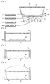
Fig. 1 is a view schematically showing a lighting device according to a first example; -
Fig. 2 is a cross sectional view showing a lighting design under an optimum condition by means of a light emitting device and an optical excitation plate ofFig. 1 -
Fig. 3 is a cross sectional view showing that a reflector are disposed on both inner walls a mixing chamber ofFig. 2 ; -
Fig. 4 is a cross sectional view showing that a lens unit is disposed on the optical excitation plate ofFig. 2 ; -
Fig. 5 is a mimetic diagram for describing a method of calculating a distance between the light emitting devices ofFigs. 2 to 4 ; -
Fig. 6 is a view showing a distance between the inner wall of the mixing chamber and the light emitting device located at the outermost ofFigs. 2 to 4 ; -
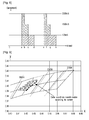
Fig. 7 is a graph showing a luminous flux change according to the distance between the light emitting devices ofFigs. 2 to 4 ; -
Fig. 8 is a graph showing a current magnitude by pulse width modulation according to the first example; -
Fig. 9 is a graph showing a color coordinate change by the pulse width modulation ofFig. 8 ; -
Fig. 10 is a view for describing a lighting control method on a black body radiation curve according to the first example; -
Fig. 11 is a view showing a principle in which a color coordinate is obtained on the black body radiation curve according to the first example; -
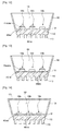
Fig. 12 is a schematic view of a lighting device according to a second example; -
Fig. 13 is a schematic view of the lighting device including two light sources according to the second example; -
Fig. 14 is a schematic view of the lighting device including an optical excitation plate according to the second example; -
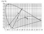
Fig. 15 is a view showing a principle in which a color coordinate is obtained on the black body radiation curve according to the second example. - Hereafter, a thickness or size of each layer is magnified, omitted or schematically shown for the purpose of convenience and clearness of description. The size of each component does not necessarily mean its actual size.
- In description of examples of the present invention, when it is mentioned that an element is formed "on" or "under"another element, it means that the mention includes a case where two elements are formed directly contacting with each other or are formed such that at least one separate element is interposed between the two elements. The "on" and "under" will be described to include the upward and downward directions based on one element.
-
Fig. 1 is a view schematically showing a lighting device according to a first example. - Referring to
Fig. 1 , the lighting device according to the first example may include aheat sink 110, alight source 130, areflector 150, anoptical excitation plate 170, a first pulse width modulation (PWM)controller 200, a second pulse width modulation (PWM)controller 300, afirst controller 400 and asecond controller 500. - First, amixing chamber (without a reference numeral) is formed by the
reflector 150 and theheat sink 110. The mixing chamber receives thelight source 130. A mixingspace 160 may be formed within the mixing chamber. The optical excitation plate 170is disposed on the upper portion of the open mixing chamber. Here, the lights which are emitted from thelight source 130 or the lights which are emitted from thelight source 130 and are reflected by thereflector 150 are mixed in the mixingspace 160. - The
heat sink 110 may receive heat from thelight source 130 and radiate the heat. Theheat sink 110 has one surface on which thelight source 130 is disposed. Here, the surface on which thelight source 130 is disposed may be flat or may have a predetermined curvature. - Also, the
heat sink 110 may have aheat radiating fin 115. Theheat radiating fin 115 may project or extend outwardly from one side of theheat sink 110. Theheat radiating fin 115 increases the heat radiating area of theheat sink 110. Therefore, heat radiation efficiency of the lighting device may be improved by theheat radiating fin 115. - Also, the
heat sink 110 may be formed of a metallic material or a resin material, each of which has excellent heat radiation efficiency. However, there is no limit to the material of theheat sink 110. For example, the material of theheat sink 110 may include at least one of Al, Ni, Cu, Ag and Sn. - The
light source 130 is disposed on theheat sink 110 and emits predetermined light above theheat sink 110. Thelight source 130 may include asubstrate 131 and alight emitting device 133. - The
substrate 131 may be one of a common PCB, a metal core PCB (MCPCB), a standard FR-4 PCB or a flexible PCB. Thesubstrate 131 may directly contact with theheat sink 110. Thesubstrate 131 may be disposed on one side of theheat sink 110. - Also, at least one light emitting
device 133 is disposed on thesubstrate 131. A light reflective material may be coated or deposited on thesubstrate 131 in order to easily reflect the light from thelight emitting device 133. - For structural purpose or so as to enhance the heat transfer to the
heat sink 110, thesubstrate 131 may selectively include a thermally conductive adhesive tape or a thermal pad. - A plurality of the
light emitting devices 133 may be disposed on thesubstrate 131. The plurality of thelight emitting devices 133 may emit light having the same wavelength or lights having mutually different wavelengths. The plurality of the light emitting devices 133may emit light having the same color or lights having mutually different colors. - Also, the
light emitting device 133 may be one of a blue light emitting device emitting blue light, a green light emitting device emitting green light, a red light emitting device emitting red light, a white light emitting device emitting white light. - The
light emitting device 133 may include a light emitting diode (LED) chip. The LED chip may be one of a blue LED chip emitting blue light in a visible light spectrum, a green LED chip emitting green light, and a red LED chip emitting red light. Here, the blue LED chip has a dominant wavelength of from about 430 nm to 480 nm. The green LED chip has a dominant wavelength of from about 510 nm to 535 nm. The red LED chip has a dominant wavelength of from about 600 nm to 630 nm. - Here, a lighting design under an optimum condition by means of the
light emitting device 133 and theoptical excitation plate 170 will be described below. - First, the mixing chamber will be omitted or schematically shown in
Figs. 2 to 4 for the sake of convenience and clarity of the following description. -
Fig. 2 is a cross sectional view showing a lighting design under an optimum condition by means of the light emitting device and the optical excitation plate ofFig. 1 . - Referring to
Fig. 2 , for the purpose of a lighting design under the optimum condition, in a state where the height of thelight emitting device 133 is fixed, the disposition interval of thelight emitting devices 133, which maximizes luminous efficiency, may be determined by using the optical orientation angle of thelight emitting device 133 and a distance between the light emittingdevice 133 and theoptical excitation plate 170. -
Fig. 3 is a cross sectional view showing that a reflector are disposed on both inner walls a mixing chamber ofFig. 2 . - Referring to
Fig. 3 , in the lighting device according to the first example, a reflector40 having the same inclined surface may be further disposed on both inner walls of a mixingchamber 10. Here, the reflector 40is disposed to totally reflect the light emitted from thelight emitting device 133. The reflector 40may be formed vertically or formed inclined to some degree. -
Fig. 4 is a cross sectional view showing that a lens unit is disposed on the optical excitation plate ofFig. 2 . - Referring to
Fig. 4 , the lighting device according to the first example may be configured by forming alens unit 50 on theoptical excitation plate 170. - Here, the
lens unit 50 may be formed with a lens so as to increase the orientation angle of the light emitted from thelight emitting device 133. Through this, thelens unit 50 is able to improve the uniformity of a linear light source of the lighting device according to the first example. - The
lens unit 50 may have any one of a concave shape, a convex shape and a hemispherical shape. Thelens unit 50 may be formed of an epoxy resin, a silicone resin, a urethane resin or a compound of them. -
Fig. 5 is a mimetic diagram for describing a method of calculating a distance between the light emitting devices ofFigs. 2 to 4 .Fig. 6 is a view showing a distance between the inner wall of the mixing chamber and the light emitting device located at the outermost ofFigs. 2 to 4 . - First, the
light emitting device 133 may be comprised of a single or a plurality of blue LEDs having a wavelength of 430 nm to 480 nm. Theoptical excitation plate 170 may be comprised of a single or a plurality of yellow phosphors and a single or a plurality of green phosphors. Here, when thelight emitting device 133 has an optical orientation angle of 100° to 120°and theoptical excitation plate 170 is comprised of a single or a plurality of yellow phosphors and a single or a plurality of green phosphors, light which passes through theoptical excitation plate 170 and is emitted may have a wavelength of 510 nm to 585nm. - Referring to
Fig. 5 , assuming that a distance between the light emittingdevice 133 and theoptical excitation plate 170 is denoted by "H" and the optical orientation angle of thelight emitting device 133 is denoted by "θ", a distance "G" between the light emittingdevices 133 can be represented by the following equation (1).
- Here, it is recommended that the distance "H" between the light emitting
device 133 and theoptical excitation plate 170 should be determined within a range in which the lights generated from thelight emitting device 133 is not superposed on each other. However, there may be an error range of less than 10 % depending on the number of thelight emitting devices 133. - In addition, when the plurality of the
light emitting devices 133 are symmetrically disposed, the distance "G" between the light emitting devices 133is minimized. - Preferably, the distance "G" between the light emitting devices 133is between 25 mm and 30 mm.
- As shown in equation (1), it can be seen that the distance "H" between the light emitting
device 133 and theoptical excitation plate 170 is determined by the distance "G" between the light emittingdevices 133 and the optical orientation angle "θ" of thelight emitting device 133. Therefore, when the distance "G" between the light emittingdevices 133 and the optical orientation angle "θ" of thelight emitting device 133 are known, the distance "H" between the light emittingdevice 133 and theoptical excitation plate 170 can be obtained by the equation (1). - Moreover, when the distance between the light emitting
device 133 and theoptical excitation plate 170 and the optical orientation angle of thelight emitting device 133 are known, the distance between the light emittingdevices 133 can be also obtained. - Next, referring to
Fig. 6 , a distance "L" between the inner wall of the mixing chamber 10and a light emitting device located at the outermost among thelight emitting devices 133 can be represented by the following equation (2).
- As shown in equation (2), the distance "L" between the inner wall of the mixing chamber 10and the
light emitting device 133 located at the outermost may be formed to be larger than a half of the distance "G" between the light emittingdevices 133. -
Fig. 7 is a graph showing a luminous flux change according to the distance between the light emitting devices ofFigs. 2 to 4 . - First, when six light emitting
devices 133 are, as shown inFig. 6 , disposed symmetrically with respect to the center, there is an experiment in which a luminous flux is changed while the disposition area of thelight emitting devices 133 is changed from 14 mm × 14 mm to 40 mm x 40 mm. - The graph of
Fig. 7 shows the result of the experiment. The result shows that the more widely thelight emitting devices 133 are distributed (that is, the larger the distance between the light emitting devices 133), the more the luminous flux is increased and then is decreased when the disposition area is greater than a certain area (for example, 27 mm x 27 mm to 29 mm x 29 mm). - In the simulation result, the maximum luminous flux is obtained when the disposition area of the
light emitting devices 133 is within a range of 27 mm x 27 mm to 29 mm x 29 mm. - As shown in the simulation result, it can be found that the luminous flux becomes different in accordance with the distance between the light emitting
devices 133 and there exists an optimum distance between the light emitting devices. - As described in
Figs. 2 to 7 , it is possible to obtain the distance between the light emittingdevices 133, which maximizes luminous efficiency, by using the optical orientation angle of thelight emitting device 133 and the distance between the light emittingdevice 133 and theoptical excitation plate 170. - Also, the distance between the light emitting
devices 133, which maximizes luminous efficiency, is represented by a relational expression, thereby obtaining a lighting design under the optimum condition. - Moreover, it is also possible to obtain the distance between the light emitting
device 133 and theoptical excitation plate 170, which maximizes luminous efficiency, only by means of the distance between the light emittingdevices 133 and the optical orientation angle of thelight emitting device 133. - Moreover, in a state where the height of the
light emitting device 133 is fixed, it is also possible to obtain a distance between the light emittingdevices 133, which maximizes luminous efficiency, only by means of the distance between the light emittingdevice 133 and theoptical excitation plate 170 and the optical orientation angle of thelight emitting device 133. - Moreover, it is also possible to overcome luminous efficiency degradation caused by the disposition of the
light emitting devices 133 and errors caused by color coordinate deviation. Accordingly, the reliability of a product can be remarkably enhanced. - Moreover, even in a case of mass production, luminous efficiency becomes higher and a desired color coordinate can be obtained.
- Moreover, in a state where the light emitting devices are disposed in such a manner as to obtain the optimum luminous efficiency, the
lens unit 50 is further disposed on theoptical excitation plate 170, so that it is possible to satisfy both of the luminous efficiency and color coordinate and to control the orientation angle of the light. - Further, Referring to
Fig. 1 , thelight emitting device 133 may further include a phosphor. The phosphor may be mixed with a solvent of resin and cover the LED chip. The phosphor may be at least one of a yellow phosphor, a green phosphor and a red phosphor. - The yellow phosphor may emit yellow light having a dominant wavelength of from 540 nm to 585 nm in response to blue light (430 nm to 480 nm) from the blue LEDchip. The green phosphor may emit green light having a dominant wavelength of from 510 nm to 535 nm in response to the blue light (430 nm to 480 nm). The red phosphor may emit red light having a dominant wavelength of from 600 nm to 650 nm in response to the blue light (430 nm to 480 nm).
- The yellow phosphor may be a silicate phosphor, a YAG of a garnet phosphor and an oxynitride phosphor. The yellow phosphor may emit light having a dominant wavelength of from 555 nm to 585 nm in response to the blue light. The yellow phosphor may be selected from Y3A15O12:Ce3+(Ce:YAG), CaAlSiN3:Ce3+ and Eu2+-SiAlON phosphor and/or may be selected from BOSE phosphor. The yellow phosphor may be doped at an arbitrary appropriate level so as to provide light output of a desired wavelength. Ce and/or Eu may be doped in the phosphor at a dopant concentration of about 0.1 % to about 20 %. A phosphor appropriate for this purpose may include products produced by Mitsubishi Chemical Company (Tokyo, Japan), Leuchtstoffwerk Breitungen GmbH(Breitungen, Germany) and Intermatix Company (Fremont, California).
- The green phosphor may be a silicate phosphor, a nitride phosphor and an oxynitride phosphor. The green phosphor may emit light having a dominant wavelength of from 510 nm to 535 nm in response to the blue light.
- The red phosphor may be a nitride phosphor and a sulfide phosphor. The red phosphor may emit light having a dominant wavelength of from 600 nm to 650 nm in response to the blue light. The red phosphor may include CaAlSiN3:Eu2+ and Sr2Si5N8:Eu2+. These phosphors are able to cause a quantum efficiency to be maintained greater than 80 % at a temperature higher than 150 °C Another usable red phosphor may be selected from not only CaSiN2:Ce3+ and CaSiN2:Eu2+ but Eu2+-SiAlON phosphor and/or may be selected from (Ca,Si,Ba)SiO4:Eu2+(BOSE) phosphor. Particularly, a CaAlSiN:Eu2+ phosphor of the Mitsubishi Chemical Company may have a dominant wavelength of about 624 nm, a peak wavelength ofabout 628 nm and FWHM of about 100 nm.
- The plurality of the
light emitting devices 133 may be comprised by combining the blue light emitting devices and the red light emitting devices or by combining the blue light emitting devices, the red light emitting devices and the green light emitting devices or may be comprised of only the white light emitting devices. - The
reflector 150 reflects the light emitted from thelight source 130. Thereflector 150 surrounds thelight source 130. Thereflector 150 is able to easily reflect outwardly the light emitted from thelight source 130. - The
reflector 150 may include a reflective surface which reflects the light emitted from thelight source 130. The reflective surface may substantially form a right angle with thesubstrate 131 or may substantially form an obtuse angle with the top surface of thesubstrate 131. The reflective surface may be coated or deposited with a material capable of easily reflecting the light. - In the first example, the
light emitting device 133 comprised of a first white light emitting device, a second white light emitting device, a third white light emitting device and a fourth white light emitting device will be taken as an example. The first white light emitting device, the second white light emitting device, the third white light emitting device and the fourth white light emitting devices are disposed in the form of a linear array in the order listed. The color temperatures of the first and the third white light emitting devices are higher than those of the second and the fourth white light emitting devices. That is, the first and the third white light emitting devices are a cool white light emitting device. The second and the fourth white light emitting devices are a warm white light emitting device. Currents applied to the first and the second white light emitting devices are pulse-width modulated respectively by thefirst PWM controller 200 and thesecond PWM controller 300, and currents applied to the third and the fourth white light emitting devices having color temperatures different from those of the first and the second white light emitting devices are controlled respectively by thefirst controller 400 and thesecond controller 500 in such a manner that a (x, y) coordinate determined by the mixture of the lights emitted from the first to the fourth white light emitting devices moves onto a black body radiation curve within a 1931 CIE chromaticity diagram. - As such, through the pulse widthmodulation of the first and the
second PWM controllers - As compared with the first and the
second controller first PWM controller 200 and thesecond PWM controller 300 generate momentarily a high pulse. Therefore, the PWM controller is broken many times. Here, even though one of the first and thesecond PWM controllers first controller 400 and thesecond controller 500. -
Fig. 8 is a graph showing a current magnitude by the pulse width modulation according to the first example.Fig. 9 is a graph showing a color coordinate change by the pulse width modulation ofFig. 8 . - Referring to
Fig. 8 , it is possible to recognize how the magnitude of the current applied to the white light emitting device is changed according to the lapse of time. Here, a duty cycle is e-a(t). - The magnitudes of the currents applied to the first white light emitting devices can be changed by the pulse width modulation of the first PWM controller. Here, an area representing the magnitude of the current during turn-on time corresponds to the brightness of the white light emitting device. Likewise, the magnitudes of the currents applied to the second white light emitting devices can be changed by the pulse width modulation of the second PWM controller.
- When the turn-on time is b-a, the current flowing through the white light emitting device is 2,500 mA. When the turn-on time is c-b, the current flowing through the white light emitting device is 1,500 mA. When the turn-on time is d-c, the current flowing through the white light emitting device is 175 mA.
- Here, the magnitudes of the currents flowing during the turn-on time are different from each other in the three cases. However, the brightnesses of the three cases are the same as each other.
- With regard to this,
Figs. 8 and 9 show the color coordinates when the current applied to the white light emitting device is 175mA, 350mA, 700mA, 1,000mA, 1,500mA, 2,000mA and2,500mA. It can be seen that the more the magnitude of the current is increased, the more (x, y) values on the (x, y) color coordinates is decreased. - In other words, when the pulse width of the current applied to the white light emitting device is modulated and decreased, the magnitude of the current flowing through the white light emitting device is increased. Therefore, the (x, y) color coordinate is located on the bottom left in the graph.
-
Fig. 10 is a view for describing a lighting control method on the black body radiation curve according to the first example. Here, the first and the second PWM controllers perform a control for the pulse width modulation of the current. The first and the second controllers perform a general control for the current. - Referring to
Fig. 10 , points A and B represent two end points of a range in which the (x, y) color coordinate of the light emitted by controlling the current applied to the cool white light emitting device (or by controlling the pulse width modulation of the current) is able to move. Points A' and B' represent two end points of a range in which the (x, y) color coordinate of the light emitted by controlling the current applied to the warm white light emitting device (or by controlling the pulse width modulation of the current) is able to move. An range in which the (x, y) color coordinate of the light emitted through the pulse width modulation of the current applied to the cool white light emitting device is able to move is located on the bottom left of a range in which the (x, y) color coordinate of the light emitted through the pulse width modulation of the current applied to the warm white light emitting device is able to move. - The first PWM controller performs a pulse width modulation on the current applied to the first white light emitting device. The second PWM controller performs a pulse width modulation on the current applied to the second white light emitting device. Due to the pulse width modulation of the first PWM controller, the cool white light emitting device has the (x, y) color coordinate on a straight line connecting the point A with the point B. Due to the pulse width modulation of the second PWM controller, the warm white light emitting device has the (x, y) color coordinate on a straight line connecting the point A' with the point B'.
- The first controller controls the current applied to the third white light emitting device. The second controller controls the current applied to the fourth white light emitting device. Due to the control of the first controller, the cool white light emitting device has the (x, y) color coordinate on a straight line connecting the point A with the point B. Due to the control of the second controller, the warm white light emitting device has the (x, y) color coordinate on a straight line connecting the point A' with the point B'.
- Here, the (x, y) color coordinate determined by the mixture of the lights emitted from the first to the fourth white light emitting devices may exist on four ranges. That is, the four ranges include 1) a range represented by a straight line connecting the point A with the point A', 2) a range a range represented by a straight line connecting the point A with the point B', 3) a range represented by a straight line connecting the point B with the point A', and 4) a range represented by a straight line connecting the point B with the point B'.
- From the above-mentioned principle, the current applied to at least one of the first and the second white light emitting devices is pulse-width modulated and the current applied to at least one of the third and the fourth white light emitting devices is controlled, so that the (x, y) coordinate determined by the mixture of the lights emitted from the first to the fourth white light emitting devices can be moved onto the black body radiation curve within the 1931 CIE chromaticity diagram.
-
Fig. 11 is a view showing a principle in which a color coordinate is obtained on the black body radiation curve according to the first example. Referring toFig. 11 , the lighting control method according to the first example will be described below. - First, a first set current and a second set current are respectively applied to the first and the second white light emitting devices disposed on the substrate, and then a (x, y) coordinate is obtained, which is determined by the mixture of the lights emitted from the first and the second white light emitting devices and is located within the 1931 CIE chromaticity diagram. Here, the (x, y) coordinate, which is determined by the mixture of the lights emitted from the first and the second white light emitting devices and is located within the 1931 CIE chromaticity diagram, exists, for example, like a point P1, within a range represented by a straight line connecting the point A and the point A'.
- Subsequently, a third set current and a fourth set current are respectively applied to the third and the fourth white light emitting devices which are disposed on the substrate and have color temperatures different from those of the first and the second white light emitting devices, and then a (x, y) coordinate is obtained, which is determined by the mixture of the lights emitted from the first to the fourth white light emitting devices and is located within the 1931 CIE chromaticity diagram. Here, the (x, y) coordinate, which is determined by the mixture of the lights emitted from the third and the fourth white light emitting devices and is located within the 1931 CIE chromaticity diagram, exists, for example, like a point P2, within a range represented by a straight line connecting the point B and the point B'. A new coordinate is obtained by mixing the obtained (x, y) coordinate which is determined by the mixture of the lights emitted from the first and the second white light emitting devices and is located within the 1931 CIE chromaticity diagram with the (x, y) coordinate, which is determined by the mixture of the lights emitted from the first to the fourth white light emitting devices and is located within the 1931 CIE chromaticity diagram. Here, there is a high probability that the new coordinate is not a point, for example, a point P3, which is located on the black body radiation curve.
- Subsequently, the current applied to at least one of the first and the second white light emitting devices is pulse-width modulated and the current applied to at least one of the third and the fourth white light emitting devices is controlled, and then the (x, y) coordinate determined by the mixture of the lights emitted from the first to the fourth white light emitting devices is moved onto the black body radiation curve within the 1931 CIE chromaticity diagram. Since the obtained the (x, y) coordinate, which is determined by the mixture of the lights emitted from the first to the fourth white light emitting devices and is located within the 1931 CIE chromaticity diagram, is not a point, for example, the point P3, which is located on the black body radiation curve, the (x, y) coordinate is moved onto a point like the point P3 on the black body radiation curve by controlling the current. Here, the currents applied to the first to the fourth white light emitting devices are independently controlled, the x value and y value of the (x, y) coordinate become smaller with the decrease of the pulse-width of the current applied to the first white light emitting device or the second white light emitting device.
-
Fig. 12 is a schematic view of a lighting device according to a second example.Fig. 13 is a schematic view of the lighting device including two light sources according to the second example.Fig. 14 is a schematic view of the lighting device including an optical excitation plate according to the second example. - Referring to
Figs. 12 to 13 , the lighting device according to the second example may include theheat sink 110, the light source and thereflector 150. - Also, referring to
Fig. 14 , the lighting device according to the second example may further include theoptical excitation plate 170. - Since the configurations of the
heat sink 110, thereflector 150 and theoptical excitation plate 170 are the same as those of the first example, detailed descriptions thereof will be omitted. - Hereafter, a description of how a light emitting device is disposed will be described in detail with the second example.
- Referring to the figure, the lighting device includes a first white
light emitting device 133a, a second whitelight emitting device 133b and a redlight emitting device 133c. - The first white
light emitting device 133a includes a first blue light emitting chip which is disposed on thesubstrate 131 and emits first blue light, and a yellow phosphor which emits yellow light in response to the first blue light emitted from the first blue light emitting chip. The yellow phosphor is a garnet (including YAG) phosphor or a silicate phosphor. - The second white
light emitting device 133b includes a second blue light emitting chip which is disposed on thesubstrate 131 and emits second blue light, and a yellow phosphor which emits yellow light in response to the second blue light emitted from the second blue light emitting chip. The first blue light and the second blue light have a wavelength of from 420 nm to 490 nm. The deviation of the wavelength has a range between 1 nm and 70 nm. For example, the wavelengths of the first blue light and the second blue light may be 455 nm and 480 nm respectively. The larger the deviations of the wavelengths of the first blue light and the second blue light become, the smaller the magnitudes of the currents applied to the first and the whitelight emitting devices133aand 133b, so that the color of the emitted light is changed. In other words, when the deviations of the wavelengths of the first blue light and the second blue light arerelatively large, the magnitude of the current required for changing the color of the emitted light is small. Like the first whitelight emitting device 133a, the yellow phosphor is a garnet (including YAG) phosphor of a silicate phosphor. - The red
light emitting device 133c is disposed on thesubstrate 131 and includes a red light emitting chip emitting red light. - Referring to the figure, the lighting device includes a first light source and a second light source.
- The first light source includes the first white
light emitting device 133a and the redlight emitting device 133c. The first whitelight emitting device 133a includes the first blue light emitting chip which is disposed on a first substrate and emits the first blue light, and the yellow phosphor which emits yellow light in response to the first blue light emitted from the first blue light emitting chip. The redlight emitting device 133c is disposed on the first substrate and includes a red light emitting chip emitting red light. The yellow phosphor is a garnet (including YAG) phosphor or a silicate phosphor. - The second light source includes the second white
light emitting device 133b. The second white light emitting device 133bincludes the second blue light emitting chip which is disposed on a second substrate and emits the second blue light, and the yellow phosphor which emits yellow light in response to the second blue light emitted from the second blue light emitting chip. The first blue light and the second blue light have a wavelength of from 420 nm to 490 nm. The deviation of the wavelength has a range between 1 nm and 70 nm. For example, the wavelengths of the first blue light and the second blue light may be 455 nm and 480 nm respectively. The larger the deviations of the wavelengths of the first blue light and the second blue light become, the smaller the magnitudes of the currents applied to the first and the white light emitting devices 133aand 133b, so that the color of the emitted light is changed. In other words, when the deviations of the wavelengths of the first blue light and the second blue light are relatively large, the magnitude of the current required for changing the color of the emitted light is small. Like the first whitelight emitting device 133a, the yellow phosphor is a garnet (including YAG) phosphor of a silicate phosphor. - While one substrate is used in the first example, the two substrates, i.e., the first and the second substrates are used and the red light emitting device is disposed only on the first substrate in the second example. However, the red light emitting device may be disposed only on the second substrate or may be disposed on both of the first and the second substrates.
- Referring to the figure, the lighting device includes a light source and the
optical excitation plate 170. - The light source includes a first blue
light emitting device 133a emitting the first blue light, a second bluelight emitting device 133b emitting the second blue light, and a redlight emitting device 133c emitting the red light. The first bluelight emitting device 133a, the second bluelight emitting device 133b and the redlight emitting device 133c are disposed on thesubstrate 131. The first blue light and the second blue light have a wavelength of from 420 nm to 490 nm. The deviation of the wavelength has a range between 1 nm and 70 nm. For example, the wavelengths of the first blue light and the second blue light may be 455 nm and 480 nm respectively. The larger the deviations of the wavelengths of the first blue light and the second blue light become, the smaller the magnitudes of the currents applied to the first and the bluelight emitting devices133aand 133b, so that the color of the emitted light is changed. In other words, when the deviations of the wavelengths of the first blue light and the second blue light are relatively large, the magnitude of the current required for changing the color of the emitted light is small. - The
optical excitation plate 170 is disposed on the light source and is disposed apart at a predetermined interval from the first bluelight emitting device 133a, the second bluelight emitting device 133b and the redlight emitting device 133c. The optical excitation plate 170includes the yellow phosphor. The yellow phosphor is a garnet (including YAG) phosphor of a silicate phosphor. Unlike the first and the second examples, since the first bluelight emitting device 133a and the second blue light emitting device 133bare not covered with the yellow phosphor, theoptical excitation plate 170 including the yellow phosphor is required to emit the white light. - Here, a lighting design under an optimum condition by means of the
light emitting devices optical excitation plate 170 is the same as that of the above-described first example, a detailed description thereof will be omitted. -
Fig. 15 is a view showing a principle in which a color coordinate is obtained on the black body radiation curve according to the second example. Here, the wavelength of the first blue light emitted from the first blue light emitting chip included in the first white light emitting device (or the first blue light emitting device) is 455 nm. The wavelength of the second blue light emitted from the second blue light emitting chip included in the second white light emitting device (or the second blue light emitting device) is 480 nm. The wavelength of the light that the yellow phosphor included in the first and the second white light emitting devices (or the yellow phosphor of the optical excitation plate) emits in response to the first blue light or the second blue light is 555 nm. The wavelength of the red light emitted from the redlight emitting device 620 nm. - Referring to
Figs. 12 and15 , a lighting control method according to the example shown inFig. 12 will be described below. - First, a first set current is applied to the first white
light emitting device 133a disposed on thesubstrate 131, and then P1, i.e., (x, y) color coordinate of the light emitted from the first whitelight emitting device 133a is obtained, which is located within the 1931 CIE chromaticity diagram. - Subsequently, a second set current is applied to the red
light emitting device 133c disposed on thesubstrate 131, and then P2, i.e., (x, y) color coordinate determined by the mixture of the lights emitted from the first whitelight emitting device 133a and the redlight emitting device 133c is obtained. - Subsequently, a third set current is applied to the second white
light emitting device 133b disposed on thesubstrate 131, and then P4, i.e., (x, y) color coordinate is obtained, which is determined by the mixture of the lights emitted from the first whitelight emitting device 133a, the redlight emitting device 133c and the second whitelight emitting device 133b. That is, while P3, i.e., (x, y) color coordinate of the light emitted from the second whitelight emitting device 133b is obtained, which is located within the 1931 CIE chromaticity diagram by applying the third set current to the second whitelight emitting device 133b disposed on thesubstrate 131, the P4, i.e., (x, y) color coordinate is obtained by mixing the lights emitted from the first whitelight emitting device 133a and the redlight emitting device 133c. - Subsequently, the current applied to at least one of the first white
light emitting device 133a, the second whitelight emitting device 133b and the redlight emitting device 133c is controlled, so that the (x, y) coordinate determined by the mixture of the lights emitted from the first whitelight emitting device 133a, the redlight emitting device 133c and the second whitelight emitting device 133b is moved onto a point P5 which is located on the black body radiation curve within the 1931 CIE chromaticity diagram. That is, since the P4 is not located on the black body radiation curve, the P4 is moved by the current control to the point P5located on the black body radiation curve. Here, the (x, y) coordinate is moved along the black body radiation curve in a direction in which the value of x is reduced. The currents applied to the first whitelight emitting device 133a, the redlight emitting device 133c and the second whitelight emitting device 133b are independently controlled. - In the lighting control method according to the example shown in
Fig. 12 , a current control device, for example, the pulse width modulation (PWM) controller, the current controller and the like is used so as to apply and control the current applied to at least one of the first whitelight emitting device 133a, the second whitelight emitting device 133b and the redlight emitting device 133c. However, there is no limit to this. Any device capable of controlling the current may be used in the lighting control method. - Referring to
Figs. 13 and15 , a lighting control method according to the example shown inFig. 13 will be described below. - First, the first set current is applied to the first white
light emitting device 133a disposed on the first substrate, and then P1, i.e., (x, y) color coordinate of the light emitted from the first whitelight emitting device 133a is obtained, which is located within the 1931 CIE chromaticity diagram. - Subsequently, the second set current is applied to the red
light emitting device 133c disposed on the first substrate, and then P2, i.e., (x, y) color coordinate determined by the mixture of the lights emitted from the first whitelight emitting device 133a and the redlight emitting device 133c is obtained. - Subsequently, the third set current is applied to the second white
light emitting device 133b disposed on the second substrate, and then P4, i.e., (x, y) color coordinate is obtained, which is determined by the mixture of the lights emitted from the first whitelight emitting device 133a, the redlight emitting device 133c and the second whitelight emitting device 133b. That is, while P3, i.e., (x, y) color coordinate of the light emitted from the second whitelight emitting device 133b is obtained, which is located within the 1931 CIE chromaticity diagram by applying the third set current to the second whitelight emitting device 133b disposed on the second substrate, the P4, i.e., (x, y) color coordinate is obtained by mixing the lights emitted from the first whitelight emitting device 133a and the redlight emitting device 133c. - Subsequently, the current applied to at least one of the first white
light emitting device 133a, the redlight emitting device 133c and the second whitelight emitting device 133b is controlled, so that the (x, y) coordinate determined by the mixture of the lights emitted from the first whitelight emitting device 133a, the redlight emitting device 133c and the second whitelight emitting device 133b is moved onto the black body radiation curve within the 1931 CIE chromaticity diagram. That is, since the P4 is not located on the black body radiation curve, the P4 is moved by the current control to the point P5located on the black body radiation curve. Here, the (x, y) coordinate is moved along the black body radiation curve in a direction in which the value of x is reduced. The currents applied to the first whitelight emitting device 133a, the redlight emitting device 133c and the second whitelight emitting device 133b are independently controlled. - In the lighting control method according to the example shown in
Fig. 13 , a current control device, for example, the pulse width modulation (PWM) controller, the current controller and the like is used so as to apply and control the current applied to at least one of the first whitelight emitting device 133a, the second whitelight emitting device 133b and the redlight emitting device 133c. However, there is no limit to this. Any device capable of controlling the current may be used in the lighting control method. - Referring to
Figs. 14 and15 , a lighting control method according to the example shown inFig. 14 will be described below. - First, the first set current is applied to the first blue
light emitting device 133a disposed on thesubstrate 131, and then P1, i.e., (x, y) color coordinate of light formed by a process in which a part of the light emitted from the first bluelight emitting device 133a is excited by the yellow phosphor is obtained, which is located within the 1931 CIE chromaticity diagram. - Subsequently, the second set current is applied to the red
light emitting device 133c disposed on thesubstrate 131, and then P2, i.e., (x, y) color coordinate of light formed by a process in which a part of the lights emitted from the first bluelight emitting device 133a and the redlight emitting device 133c is excited by the yellow phosphor is obtained. - Subsequently, the third set current is applied to the second blue
light emitting device 133b disposed on thesubstrate 131, and then P4 , i.e., (x, y) color coordinate of light formed by a process in which a part of the lights emitted from the first bluelight emitting device 133a, the redlight emitting device 133c and the second bluelight emitting device 133b is excited by the yellow phosphor is obtained. That is, while P3, i.e., (x, y) color coordinate of the light emitted from the second whitelight emitting device 133b is obtained, which is located within the 1931 CIE chromaticity diagram by applying the third set current to the second whitelight emitting device 133b disposed on thesubstrate 131, the P4, i.e., (x, y) color coordinate is obtained by mixing the lights emitted from the first whitelight emitting device 133a and the redlight emitting device 133c. - Subsequently, the current applied to at least one of the first blue
light emitting device 133a, the redlight emitting device 133c and the second bluelight emitting device 133b is controlled, so that the (x, y) coordinate of light formed by a process in which a part of the lights emitted from the first whitelight emitting device 133a, the redlight emitting device 133c and the second bluelight emitting device 133b is excited by the yellow phosphor is moved onto the black body radiation curve within the 1931 CIE chromaticity diagram. That is, since the P4 is not located on the black body radiation curve, the P4 is moved by the current control to the point P5located on the black body radiation curve. Here, the (x, y) coordinate is moved along the black body radiation curve in a direction in which the value of x is reduced. The currents applied to the first bluelight emitting device 133a, the redlight emitting device 133c and the second bluelight emitting device 133b are independently controlled. - In the lighting control method according to the example shown in
Fig. 14 , a current control device, for example, the pulse width modulation (PWM) controller, the current controller and the like is used so as to apply and control the current applied to at least one of the first bluelight emitting device 133a, the second bluelight emitting device 133b and the redlight emitting device 133c. However, there is no limit to this. Any device capable of controlling the current may be used in the lighting control method.
Claims (11)
- A lighting device comprising:a first to a fourth light emitting devices (133) which are disposed on a substrate (131);a first and a second pulse width modulation controllers (200, 300) which perform a pulse width modulation on currents applied to the first and the second light emitting devices respectively; anda first and a second controllers (400, 500) which control respectively currents applied to the third and the fourth light emitting devices having color temperatures different from those of the first and the second light emitting devices,wherein an "x, y" coordinate, which is determined by the mixture of the lights emitted from the first to the fourth light emitting devices (133) and is located within a 1931 CIE chromaticity diagram, is moved onto a black body radiation curve within the 1931 CIE chromaticity diagram through the pulse width modulation of the first and the second pulse width modulation controllers (200, 300) and the control of the first and the second controllers (400, 500),
wherein the lighting device comprises a mixing chamber (150, 10) which receives the first to the fourth light emitting devices (133) and has an open upper portion; and an optical excitation plate (170) which is disposed on the mixing chamber (150, 10) and is spaced apart from the first to the fourth light emitting devices (133), and
wherein a distance (H) between the optical excitation plate (170) and the first to the fourth light emitting devices (133) is determined by an optical orientation angle (θ) of each of the first to the fourth light emitting devices (133) and a distance (G) between the light emitting devices
wherein the first light emitting device, the second light emitting device, the third light emitting device and the fourth light emitting device are disposed in the form of a linear array in the order listed, characterized in that,
the distance (G) between the light emitting devices among the first to the fourth light emitting devices (133) is calculated by an equation of G = 2Htan(θ/2),
color temperatures of the first and the third light emitting devices are higher than those of the second and the fourth light emitting devices, the first to the fourth light emitting devices being symmetrically disposed, the distance (G) between the light emitting devices (133) being minimized. - The lighting device of claim 1, wherein the first and the third light emitting devices are a cool white light emitting device, and wherein the second and the fourth light emitting devices are a warm white light emitting device.
- The lighting device of any one claim of claims 1 or 2, wherein As compared with the first and the second controllers (400, 500), the first and the second PWM controllers (200, 300) generate momentarily a high pulse.
- The lighting device of any one claim of claims 1 to 3, wherein a distance (L) between an inner wall of the mixing chamber (150, 10) and a light emitting device located at the outermost among the first to the fourth light emitting devices (133) is calculated by an equation of L ≥ G/2.
- The lighting device of claim 1, wherein the distance (H) between the first to the fourth light emitting devices (133) and the optical excitation plate (170) is determined within a range in which lights generated from each of the light emitting devices are not superposed on each other or are superposed on each other by less than 10 %.
- The lighting device of claim 1, wherein the distance (G) between two adjacent light emitting devices among the first to the fourth light emitting devices (133) is between 25 mm and 30 mm.
- The lighting device of claim 1, wherein both inner walls of the mixing chamber (150, 10) are equally vertical or equally inclined.
- The lighting device of claim 1, further comprising a reflector (40) which is disposed to have the same inclined surfaces on both inner walls of the mixing chamber (10).
- The lighting device of claim 1, further comprising a lens unit (50) which is disposed on the optical excitation plate (170) and adjusts an orientation angle of the light.
- The lighting device of claim 9, wherein the lens unit (50) has any one of a concave shape, a convex shape and a hemispherical shape and is formed of any one of an epoxy resin, a silicone resin, a urethane resin or a compound of them.
- A lighting control method of any one claim of claims 1 to 10 comprising:a first step of applying a first set current and a second set current to the first and the second light emitting devices respectively, and of obtaining a "x, y" coordinate which is determined by the mixture of the lights emitted from the first and the second light emitting devices and is located within a 1931 CIE chromaticity diagrama second step of respectively applying a third set current and a fourth set current to the third and the fourth light emitting devices having color temperatures different from those of the first and the second light emitting devices, and of obtaining a "x, y" coordinate which is determined by the mixture of the lights emitted from the first to the fourth light emitting devices and is located within the 1931 CIE chromaticity diagram anda third step of pulse-width modulating the current applied to at least one of the first and the second light emitting devices, of controlling the current applied to at least one of the third and the fourth light emitting devices, and of moving the "x, y" coordinate determined by the mixture of the lights emitted from the first to the fourth light emitting devices onto a black body radiation curve within the 1931 CIE chromaticity diagram.
Priority Applications (1)
| Application Number | Priority Date | Filing Date | Title |
|---|---|---|---|
| EP16188395.4A EP3156722B1 (en) | 2011-09-08 | 2012-09-07 | Lighting device and lighting control method |
Applications Claiming Priority (4)
| Application Number | Priority Date | Filing Date | Title |
|---|---|---|---|
| KR1020110091148A KR20130027741A (en) | 2011-09-08 | 2011-09-08 | Lighting device and lighting control method |
| KR1020110091147A KR20130027740A (en) | 2011-09-08 | 2011-09-08 | Lighting device and lighting control method |
| KR1020110129351A KR101272691B1 (en) | 2011-12-06 | 2011-12-06 | Lighting device |
| PCT/KR2012/007223 WO2013036070A2 (en) | 2011-09-08 | 2012-09-07 | Lighting device and lighting control method |
Related Child Applications (2)
| Application Number | Title | Priority Date | Filing Date |
|---|---|---|---|
| EP16188395.4A Division EP3156722B1 (en) | 2011-09-08 | 2012-09-07 | Lighting device and lighting control method |
| EP16188395.4A Division-Into EP3156722B1 (en) | 2011-09-08 | 2012-09-07 | Lighting device and lighting control method |
Publications (3)
| Publication Number | Publication Date |
|---|---|
| EP2753871A2 EP2753871A2 (en) | 2014-07-16 |
| EP2753871A4 EP2753871A4 (en) | 2014-11-05 |
| EP2753871B1 true EP2753871B1 (en) | 2016-11-02 |
Family
ID=47832724
Family Applications (2)
| Application Number | Title | Priority Date | Filing Date |
|---|---|---|---|
| EP12829863.5A Active EP2753871B1 (en) | 2011-09-08 | 2012-09-07 | Lighting device and lighting control method |
| EP16188395.4A Active EP3156722B1 (en) | 2011-09-08 | 2012-09-07 | Lighting device and lighting control method |
Family Applications After (1)
| Application Number | Title | Priority Date | Filing Date |
|---|---|---|---|
| EP16188395.4A Active EP3156722B1 (en) | 2011-09-08 | 2012-09-07 | Lighting device and lighting control method |
Country Status (4)
| Country | Link |
|---|---|
| US (1) | US20140246990A1 (en) |
| EP (2) | EP2753871B1 (en) |
| JP (1) | JP6215207B2 (en) |
| WO (1) | WO2013036070A2 (en) |
Families Citing this family (24)
| Publication number | Priority date | Publication date | Assignee | Title |
|---|---|---|---|---|
| DE102013217055B4 (en) | 2013-05-17 | 2022-08-25 | Tridonic Gmbh & Co Kg | White light LED module for object lighting |
| CN103486466B (en) * | 2013-08-26 | 2015-07-08 | 深圳大学 | LED (light-emitting diode) lamp |
| JP2015092529A (en) * | 2013-10-01 | 2015-05-14 | ソニー株式会社 | Light-emitting device, light-emitting unit, display device, electronic apparatus, and light-emitting element |
| JP6682433B2 (en) * | 2013-11-13 | 2020-04-15 | エルジー イノテック カンパニー リミテッド | Blue-green phosphor, light emitting device package including the same, and lighting device |
| KR102112638B1 (en) * | 2014-02-07 | 2020-05-19 | 삼성디스플레이 주식회사 | Display apparatus |
| KR101616193B1 (en) | 2014-09-03 | 2016-04-29 | 송인실 | Apparstus for generating mixed light |
| KR20170069240A (en) * | 2014-10-01 | 2017-06-20 | 코닌클리케 필립스 엔.브이. | Light source with tunable emission spectrum |
| JP6367471B2 (en) * | 2015-03-23 | 2018-08-01 | 株式会社東芝 | Lighting system and lighting method for indoor exhibition lighting |
| JP6478755B2 (en) * | 2015-03-26 | 2019-03-06 | シャープ株式会社 | Backlight device and liquid crystal display device having the same |
| US10244601B2 (en) * | 2015-05-26 | 2019-03-26 | Philips Lighting Holding B.V. | Switchable high color contrast lighting |
| WO2017014564A1 (en) * | 2015-07-23 | 2017-01-26 | 서울반도체 주식회사 | Display device and method for manufacturing same |
| KR102417208B1 (en) * | 2015-09-02 | 2022-07-08 | 쑤저우 레킨 세미컨덕터 컴퍼니 리미티드 | Light emitting module and lighting apparatus |
| KR102524805B1 (en) | 2016-02-12 | 2023-04-25 | 삼성전자주식회사 | Lighting source module, display panel and display apparatus |
| JP6728931B2 (en) * | 2016-04-21 | 2020-07-22 | セイコーエプソン株式会社 | Light source device and projector |
| US10656019B2 (en) | 2016-07-22 | 2020-05-19 | Nichia Corporation | Method of determining chromaticity rank of light emitting device |
| KR102170024B1 (en) * | 2016-10-04 | 2020-10-26 | 도레이 카부시키가이샤 | Light source unit, and display and lighting devices using the same |
| JP6872720B2 (en) * | 2017-03-28 | 2021-05-19 | パナソニックIpマネジメント株式会社 | Lighting device |
| DE102018106958A1 (en) | 2017-03-24 | 2018-09-27 | Panasonic Intellectual Property Management Co., Ltd. | Lighting device and lighting system |
| CN107121837B (en) * | 2017-06-12 | 2020-01-03 | 武汉华星光电技术有限公司 | Backlight module and liquid crystal display device |
| EP3503687B1 (en) * | 2017-12-20 | 2020-08-05 | OSRAM GmbH | A lighting device and corresponding method for chromatic compensation |
| US10136489B1 (en) * | 2017-12-20 | 2018-11-20 | Lumileds Llc | Illumination system including tunable light engine |
| JP7089181B2 (en) | 2018-10-12 | 2022-06-22 | 日亜化学工業株式会社 | Light emitting device |
| JP2020140792A (en) * | 2019-02-27 | 2020-09-03 | ローム株式会社 | LED lighting device |
| CN112212986B (en) * | 2020-08-26 | 2021-12-28 | 武汉高德智感科技有限公司 | Infrared module data acquisition equipment and acquisition method |
Family Cites Families (18)
| Publication number | Priority date | Publication date | Assignee | Title |
|---|---|---|---|---|
| US7066623B2 (en) * | 2003-12-19 | 2006-06-27 | Soo Ghee Lee | Method and apparatus for producing untainted white light using off-white light emitting diodes |
| JP4770199B2 (en) * | 2005-03-01 | 2011-09-14 | パナソニック電工株式会社 | Illumination light source, illumination device, and display device |
| JP2007227681A (en) * | 2006-02-23 | 2007-09-06 | Matsushita Electric Works Ltd | White lighting system using light-emitting diode |
| KR101262092B1 (en) * | 2006-09-07 | 2013-05-14 | 엘지디스플레이 주식회사 | Structure of edge-type LED |
| CN101821544B (en) * | 2007-10-10 | 2012-11-28 | 科锐公司 | Lighting device and method of making |
| JP5320993B2 (en) * | 2007-11-12 | 2013-10-23 | 三菱化学株式会社 | Lighting device |
| US20100327306A1 (en) * | 2008-02-11 | 2010-12-30 | Koninklijke Philips Electronics N.V. | Led based light source for improved color saturation |
| JP4474491B1 (en) * | 2009-08-11 | 2010-06-02 | キヤノン・コンポーネンツ株式会社 | White light emitting device and line illumination device using the same |
| RU2508616C2 (en) * | 2008-02-27 | 2014-02-27 | Конинклейке Филипс Электроникс Н.В. | Illumination device with led and one or more transmitting windows |
| WO2010052640A1 (en) * | 2008-11-06 | 2010-05-14 | Koninklijke Philips Electronics N.V. | Illumination device |
| JP2010118531A (en) * | 2008-11-13 | 2010-05-27 | Stanley Electric Co Ltd | White lighting system and lighting fixture for vehicle |
| US8339029B2 (en) * | 2009-02-19 | 2012-12-25 | Cree, Inc. | Light emitting devices and systems having tunable chromaticity |
| JP2010250037A (en) * | 2009-04-15 | 2010-11-04 | Toppan Printing Co Ltd | Optical component, backlight unit and display apparatus |
| US8716952B2 (en) * | 2009-08-04 | 2014-05-06 | Cree, Inc. | Lighting device having first, second and third groups of solid state light emitters, and lighting arrangement |
| KR20110059666A (en) * | 2009-11-24 | 2011-06-03 | 엘지디스플레이 주식회사 | Back light unit, and liquid crystal display device using the same |
| CN102313249B (en) * | 2010-07-01 | 2014-11-26 | 惠州元晖光电股份有限公司 | Tunable white color methods and uses thereof |
| US8912905B2 (en) * | 2011-02-28 | 2014-12-16 | Chon Meng Wong | LED lighting system |
| US8847513B2 (en) * | 2011-03-08 | 2014-09-30 | Cree, Inc. | Method and apparatus for controlling light output color and/or brightness |
-
2012
- 2012-09-07 US US13/809,535 patent/US20140246990A1/en not_active Abandoned
- 2012-09-07 EP EP12829863.5A patent/EP2753871B1/en active Active
- 2012-09-07 WO PCT/KR2012/007223 patent/WO2013036070A2/en active Application Filing
- 2012-09-07 EP EP16188395.4A patent/EP3156722B1/en active Active
- 2012-09-07 JP JP2014529619A patent/JP6215207B2/en active Active
Also Published As
| Publication number | Publication date |
|---|---|
| WO2013036070A2 (en) | 2013-03-14 |
| JP6215207B2 (en) | 2017-10-18 |
| JP2014531709A (en) | 2014-11-27 |
| EP3156722A3 (en) | 2017-06-07 |
| EP2753871A4 (en) | 2014-11-05 |
| US20140246990A1 (en) | 2014-09-04 |
| EP2753871A2 (en) | 2014-07-16 |
| CN103782092A (en) | 2014-05-07 |
| EP3156722B1 (en) | 2019-05-22 |
| EP3156722A2 (en) | 2017-04-19 |
| WO2013036070A3 (en) | 2013-05-02 |
Similar Documents
| Publication | Publication Date | Title |
|---|---|---|
| EP2753871B1 (en) | Lighting device and lighting control method | |
| US9192013B1 (en) | Lighting devices with variable gamut | |
| EP3011804B1 (en) | Lighting device comprising at least two sets of light emitting diodes | |
| TWI463636B (en) | High cri lighting device with added long-wavelength blue color | |
| US8963168B1 (en) | LED lamp using blue and cyan LEDs and a phosphor | |
| US9241384B2 (en) | Solid state lighting devices with adjustable color point | |
| US9530944B2 (en) | High color-saturation lighting devices with enhanced long wavelength illumination | |
| US8884508B2 (en) | Solid state lighting device including multiple wavelength conversion materials | |
| US8664846B2 (en) | Solid state lighting device including green shifted red component | |
| US9215761B2 (en) | Solid state lighting devices with color point non-coincident with blackbody locus | |
| JP2008218485A (en) | Light emitting device | |
| KR20120093181A (en) | Solid state lighting devices including light mixtures | |
| CN103828487A (en) | Semiconductor light emitting devices having selectable and/or adjustable color points and related methods | |
| JP2008218486A (en) | Light emitting device | |
| US9593812B2 (en) | High CRI solid state lighting devices with enhanced vividness | |
| US10672957B2 (en) | LED apparatuses and methods for high lumen output density | |
| US20130221873A1 (en) | Led color channels including phosphor-based leds for high luminous efficacy light source | |
| KR20130027740A (en) | Lighting device and lighting control method | |
| KR20130027741A (en) | Lighting device and lighting control method | |
| CN103782092B (en) | Illuminator and illumination control method | |
| KR20130027739A (en) | Lighting device and lighting control method | |
| Galvez et al. | LED lamp |
Legal Events
| Date | Code | Title | Description |
|---|---|---|---|
| PUAI | Public reference made under article 153(3) epc to a published international application that has entered the european phase |
Free format text: ORIGINAL CODE: 0009012 |
|
| 17P | Request for examination filed |
Effective date: 20140314 |
|
| AK | Designated contracting states |
Kind code of ref document: A2 Designated state(s): AL AT BE BG CH CY CZ DE DK EE ES FI FR GB GR HR HU IE IS IT LI LT LU LV MC MK MT NL NO PL PT RO RS SE SI SK SM TR |
|
| A4 | Supplementary search report drawn up and despatched |
Effective date: 20141009 |
|
| RIC1 | Information provided on ipc code assigned before grant |
Ipc: F21V 14/00 20060101AFI20141002BHEP Ipc: F21V 9/08 20060101ALI20141002BHEP Ipc: G03B 21/20 20060101ALI20141002BHEP Ipc: H05B 37/02 20060101ALI20141002BHEP Ipc: F21K 99/00 20100101ALI20141002BHEP |
|
| DAX | Request for extension of the european patent (deleted) | ||
| 17Q | First examination report despatched |
Effective date: 20150708 |
|
| GRAP | Despatch of communication of intention to grant a patent |
Free format text: ORIGINAL CODE: EPIDOSNIGR1 |
|
| INTG | Intention to grant announced |
Effective date: 20160513 |
|
| GRAS | Grant fee paid |
Free format text: ORIGINAL CODE: EPIDOSNIGR3 |
|
| GRAA | (expected) grant |
Free format text: ORIGINAL CODE: 0009210 |
|
| AK | Designated contracting states |
Kind code of ref document: B1 Designated state(s): AL AT BE BG CH CY CZ DE DK EE ES FI FR GB GR HR HU IE IS IT LI LT LU LV MC MK MT NL NO PL PT RO RS SE SI SK SM TR |
|
| REG | Reference to a national code |
Ref country code: GB Ref legal event code: FG4D |
|
| REG | Reference to a national code |
Ref country code: AT Ref legal event code: REF Ref document number: 842212 Country of ref document: AT Kind code of ref document: T Effective date: 20161115 Ref country code: CH Ref legal event code: EP |
|
| REG | Reference to a national code |
Ref country code: IE Ref legal event code: FG4D |
|
| REG | Reference to a national code |
Ref country code: DE Ref legal event code: R096 Ref document number: 602012024986 Country of ref document: DE |
|
| REG | Reference to a national code |
Ref country code: NL Ref legal event code: FP |
|
| PG25 | Lapsed in a contracting state [announced via postgrant information from national office to epo] |
Ref country code: LV Free format text: LAPSE BECAUSE OF FAILURE TO SUBMIT A TRANSLATION OF THE DESCRIPTION OR TO PAY THE FEE WITHIN THE PRESCRIBED TIME-LIMIT Effective date: 20161102 |
|
| REG | Reference to a national code |
Ref country code: LT Ref legal event code: MG4D |
|
| REG | Reference to a national code |
Ref country code: AT Ref legal event code: MK05 Ref document number: 842212 Country of ref document: AT Kind code of ref document: T Effective date: 20161102 |
|
| PG25 | Lapsed in a contracting state [announced via postgrant information from national office to epo] |
Ref country code: LT Free format text: LAPSE BECAUSE OF FAILURE TO SUBMIT A TRANSLATION OF THE DESCRIPTION OR TO PAY THE FEE WITHIN THE PRESCRIBED TIME-LIMIT Effective date: 20161102 Ref country code: GR Free format text: LAPSE BECAUSE OF FAILURE TO SUBMIT A TRANSLATION OF THE DESCRIPTION OR TO PAY THE FEE WITHIN THE PRESCRIBED TIME-LIMIT Effective date: 20170203 Ref country code: SE Free format text: LAPSE BECAUSE OF FAILURE TO SUBMIT A TRANSLATION OF THE DESCRIPTION OR TO PAY THE FEE WITHIN THE PRESCRIBED TIME-LIMIT Effective date: 20161102 Ref country code: NO Free format text: LAPSE BECAUSE OF FAILURE TO SUBMIT A TRANSLATION OF THE DESCRIPTION OR TO PAY THE FEE WITHIN THE PRESCRIBED TIME-LIMIT Effective date: 20170202 |
|
| RAP2 | Party data changed (patent owner data changed or rights of a patent transferred) |
Owner name: LG INNOTEK CO., LTD. |
|
| PG25 | Lapsed in a contracting state [announced via postgrant information from national office to epo] |
Ref country code: AT Free format text: LAPSE BECAUSE OF FAILURE TO SUBMIT A TRANSLATION OF THE DESCRIPTION OR TO PAY THE FEE WITHIN THE PRESCRIBED TIME-LIMIT Effective date: 20161102 Ref country code: PL Free format text: LAPSE BECAUSE OF FAILURE TO SUBMIT A TRANSLATION OF THE DESCRIPTION OR TO PAY THE FEE WITHIN THE PRESCRIBED TIME-LIMIT Effective date: 20161102 Ref country code: RS Free format text: LAPSE BECAUSE OF FAILURE TO SUBMIT A TRANSLATION OF THE DESCRIPTION OR TO PAY THE FEE WITHIN THE PRESCRIBED TIME-LIMIT Effective date: 20161102 Ref country code: FI Free format text: LAPSE BECAUSE OF FAILURE TO SUBMIT A TRANSLATION OF THE DESCRIPTION OR TO PAY THE FEE WITHIN THE PRESCRIBED TIME-LIMIT Effective date: 20161102 Ref country code: HR Free format text: LAPSE BECAUSE OF FAILURE TO SUBMIT A TRANSLATION OF THE DESCRIPTION OR TO PAY THE FEE WITHIN THE PRESCRIBED TIME-LIMIT Effective date: 20161102 Ref country code: ES Free format text: LAPSE BECAUSE OF FAILURE TO SUBMIT A TRANSLATION OF THE DESCRIPTION OR TO PAY THE FEE WITHIN THE PRESCRIBED TIME-LIMIT Effective date: 20161102 Ref country code: IS Free format text: LAPSE BECAUSE OF FAILURE TO SUBMIT A TRANSLATION OF THE DESCRIPTION OR TO PAY THE FEE WITHIN THE PRESCRIBED TIME-LIMIT Effective date: 20170302 Ref country code: PT Free format text: LAPSE BECAUSE OF FAILURE TO SUBMIT A TRANSLATION OF THE DESCRIPTION OR TO PAY THE FEE WITHIN THE PRESCRIBED TIME-LIMIT Effective date: 20170302 |
|
| PG25 | Lapsed in a contracting state [announced via postgrant information from national office to epo] |
Ref country code: SK Free format text: LAPSE BECAUSE OF FAILURE TO SUBMIT A TRANSLATION OF THE DESCRIPTION OR TO PAY THE FEE WITHIN THE PRESCRIBED TIME-LIMIT Effective date: 20161102 Ref country code: DK Free format text: LAPSE BECAUSE OF FAILURE TO SUBMIT A TRANSLATION OF THE DESCRIPTION OR TO PAY THE FEE WITHIN THE PRESCRIBED TIME-LIMIT Effective date: 20161102 Ref country code: EE Free format text: LAPSE BECAUSE OF FAILURE TO SUBMIT A TRANSLATION OF THE DESCRIPTION OR TO PAY THE FEE WITHIN THE PRESCRIBED TIME-LIMIT Effective date: 20161102 Ref country code: RO Free format text: LAPSE BECAUSE OF FAILURE TO SUBMIT A TRANSLATION OF THE DESCRIPTION OR TO PAY THE FEE WITHIN THE PRESCRIBED TIME-LIMIT Effective date: 20161102 Ref country code: CZ Free format text: LAPSE BECAUSE OF FAILURE TO SUBMIT A TRANSLATION OF THE DESCRIPTION OR TO PAY THE FEE WITHIN THE PRESCRIBED TIME-LIMIT Effective date: 20161102 |
|
| REG | Reference to a national code |
Ref country code: DE Ref legal event code: R097 Ref document number: 602012024986 Country of ref document: DE |
|
| REG | Reference to a national code |
Ref country code: FR Ref legal event code: PLFP Year of fee payment: 6 |
|
| PG25 | Lapsed in a contracting state [announced via postgrant information from national office to epo] |
Ref country code: BE Free format text: LAPSE BECAUSE OF FAILURE TO SUBMIT A TRANSLATION OF THE DESCRIPTION OR TO PAY THE FEE WITHIN THE PRESCRIBED TIME-LIMIT Effective date: 20161102 Ref country code: SM Free format text: LAPSE BECAUSE OF FAILURE TO SUBMIT A TRANSLATION OF THE DESCRIPTION OR TO PAY THE FEE WITHIN THE PRESCRIBED TIME-LIMIT Effective date: 20161102 Ref country code: BG Free format text: LAPSE BECAUSE OF FAILURE TO SUBMIT A TRANSLATION OF THE DESCRIPTION OR TO PAY THE FEE WITHIN THE PRESCRIBED TIME-LIMIT Effective date: 20170202 Ref country code: IT Free format text: LAPSE BECAUSE OF FAILURE TO SUBMIT A TRANSLATION OF THE DESCRIPTION OR TO PAY THE FEE WITHIN THE PRESCRIBED TIME-LIMIT Effective date: 20161102 |
|
| PLBE | No opposition filed within time limit |
Free format text: ORIGINAL CODE: 0009261 |
|
| STAA | Information on the status of an ep patent application or granted ep patent |
Free format text: STATUS: NO OPPOSITION FILED WITHIN TIME LIMIT |
|
| 26N | No opposition filed |
Effective date: 20170803 |
|
| PG25 | Lapsed in a contracting state [announced via postgrant information from national office to epo] |
Ref country code: SI Free format text: LAPSE BECAUSE OF FAILURE TO SUBMIT A TRANSLATION OF THE DESCRIPTION OR TO PAY THE FEE WITHIN THE PRESCRIBED TIME-LIMIT Effective date: 20161102 |
|
| REG | Reference to a national code |
Ref country code: CH Ref legal event code: PL |
|
| PG25 | Lapsed in a contracting state [announced via postgrant information from national office to epo] |
Ref country code: MC Free format text: LAPSE BECAUSE OF FAILURE TO SUBMIT A TRANSLATION OF THE DESCRIPTION OR TO PAY THE FEE WITHIN THE PRESCRIBED TIME-LIMIT Effective date: 20161102 |
|
| REG | Reference to a national code |
Ref country code: IE Ref legal event code: MM4A |
|
| PG25 | Lapsed in a contracting state [announced via postgrant information from national office to epo] |
Ref country code: LU Free format text: LAPSE BECAUSE OF NON-PAYMENT OF DUE FEES Effective date: 20170907 |
|
| PG25 | Lapsed in a contracting state [announced via postgrant information from national office to epo] |
Ref country code: CH Free format text: LAPSE BECAUSE OF NON-PAYMENT OF DUE FEES Effective date: 20170930 Ref country code: IE Free format text: LAPSE BECAUSE OF NON-PAYMENT OF DUE FEES Effective date: 20170907 Ref country code: LI Free format text: LAPSE BECAUSE OF NON-PAYMENT OF DUE FEES Effective date: 20170930 |
|
| REG | Reference to a national code |
Ref country code: FR Ref legal event code: PLFP Year of fee payment: 7 |
|
| PG25 | Lapsed in a contracting state [announced via postgrant information from national office to epo] |
Ref country code: MT Free format text: LAPSE BECAUSE OF NON-PAYMENT OF DUE FEES Effective date: 20170907 |
|
| PG25 | Lapsed in a contracting state [announced via postgrant information from national office to epo] |
Ref country code: HU Free format text: LAPSE BECAUSE OF FAILURE TO SUBMIT A TRANSLATION OF THE DESCRIPTION OR TO PAY THE FEE WITHIN THE PRESCRIBED TIME-LIMIT; INVALID AB INITIO Effective date: 20120907 |
|
| PG25 | Lapsed in a contracting state [announced via postgrant information from national office to epo] |
Ref country code: CY Free format text: LAPSE BECAUSE OF NON-PAYMENT OF DUE FEES Effective date: 20161102 |
|
| PG25 | Lapsed in a contracting state [announced via postgrant information from national office to epo] |
Ref country code: MK Free format text: LAPSE BECAUSE OF FAILURE TO SUBMIT A TRANSLATION OF THE DESCRIPTION OR TO PAY THE FEE WITHIN THE PRESCRIBED TIME-LIMIT Effective date: 20161102 |
|
| PG25 | Lapsed in a contracting state [announced via postgrant information from national office to epo] |
Ref country code: TR Free format text: LAPSE BECAUSE OF FAILURE TO SUBMIT A TRANSLATION OF THE DESCRIPTION OR TO PAY THE FEE WITHIN THE PRESCRIBED TIME-LIMIT Effective date: 20161102 |
|
| PG25 | Lapsed in a contracting state [announced via postgrant information from national office to epo] |
Ref country code: AL Free format text: LAPSE BECAUSE OF FAILURE TO SUBMIT A TRANSLATION OF THE DESCRIPTION OR TO PAY THE FEE WITHIN THE PRESCRIBED TIME-LIMIT Effective date: 20161102 |
|
| REG | Reference to a national code |
Ref country code: NL Ref legal event code: PD Owner name: SUZHOU LEKIN SEMICONDUCTOR CO., LTD.; CN Free format text: DETAILS ASSIGNMENT: CHANGE OF OWNER(S), ASSIGNMENT; FORMER OWNER NAME: LG INNOTEK CO., LTD. Effective date: 20210719 Ref country code: GB Ref legal event code: 732E Free format text: REGISTERED BETWEEN 20210722 AND 20210728 |
|
| REG | Reference to a national code |
Ref country code: DE Ref legal event code: R081 Ref document number: 602012024986 Country of ref document: DE Owner name: SUZHOU LEKIN SEMICONDUCTOR CO. LTD., TAICANG, CN Free format text: FORMER OWNER: LG INNOTEK CO., LTD., SEOUL, KR |
|
| PGFP | Annual fee paid to national office [announced via postgrant information from national office to epo] |
Ref country code: NL Payment date: 20230816 Year of fee payment: 12 |
|
| PGFP | Annual fee paid to national office [announced via postgrant information from national office to epo] |
Ref country code: GB Payment date: 20230803 Year of fee payment: 12 |
|
| PGFP | Annual fee paid to national office [announced via postgrant information from national office to epo] |
Ref country code: FR Payment date: 20230808 Year of fee payment: 12 Ref country code: DE Payment date: 20230808 Year of fee payment: 12 |