EP2751592B1 - Flexibler röntgenstrahldetektor mit optischer formmessung - Google Patents
Flexibler röntgenstrahldetektor mit optischer formmessung Download PDFInfo
- Publication number
- EP2751592B1 EP2751592B1 EP12812343.7A EP12812343A EP2751592B1 EP 2751592 B1 EP2751592 B1 EP 2751592B1 EP 12812343 A EP12812343 A EP 12812343A EP 2751592 B1 EP2751592 B1 EP 2751592B1
- Authority
- EP
- European Patent Office
- Prior art keywords
- radiation
- sensor device
- optical
- dose
- cladding
- Prior art date
- Legal status (The legal status is an assumption and is not a legal conclusion. Google has not performed a legal analysis and makes no representation as to the accuracy of the status listed.)
- Not-in-force
Links
- 230000003287 optical effect Effects 0.000 title claims description 52
- 230000005855 radiation Effects 0.000 claims description 100
- 238000005253 cladding Methods 0.000 claims description 39
- 239000013307 optical fiber Substances 0.000 claims description 36
- 238000001959 radiotherapy Methods 0.000 claims description 35
- 238000000034 method Methods 0.000 claims description 33
- 239000000835 fiber Substances 0.000 claims description 21
- 230000035945 sensitivity Effects 0.000 claims description 7
- 238000005259 measurement Methods 0.000 description 16
- 206010028980 Neoplasm Diseases 0.000 description 11
- 230000033001 locomotion Effects 0.000 description 9
- 238000001228 spectrum Methods 0.000 description 6
- 230000008901 benefit Effects 0.000 description 5
- 238000003384 imaging method Methods 0.000 description 5
- 210000000056 organ Anatomy 0.000 description 4
- 239000000523 sample Substances 0.000 description 4
- 238000004458 analytical method Methods 0.000 description 3
- 239000011159 matrix material Substances 0.000 description 3
- 238000002168 optical frequency-domain reflectometry Methods 0.000 description 3
- 230000029058 respiratory gaseous exchange Effects 0.000 description 3
- 238000002560 therapeutic procedure Methods 0.000 description 3
- 238000005452 bending Methods 0.000 description 2
- 238000001514 detection method Methods 0.000 description 2
- 230000000694 effects Effects 0.000 description 2
- 239000011521 glass Substances 0.000 description 2
- 238000005305 interferometry Methods 0.000 description 2
- 238000013507 mapping Methods 0.000 description 2
- 238000012014 optical coherence tomography Methods 0.000 description 2
- 238000005070 sampling Methods 0.000 description 2
- 230000003595 spectral effect Effects 0.000 description 2
- VMYYKVWQPKPUIY-UHFFFAOYSA-N CCCCC1(CCCC2)C2C1C Chemical compound CCCCC1(CCCC2)C2C1C VMYYKVWQPKPUIY-UHFFFAOYSA-N 0.000 description 1
- 210000003484 anatomy Anatomy 0.000 description 1
- 230000009286 beneficial effect Effects 0.000 description 1
- 239000012472 biological sample Substances 0.000 description 1
- 230000000747 cardiac effect Effects 0.000 description 1
- 238000004891 communication Methods 0.000 description 1
- 230000001419 dependent effect Effects 0.000 description 1
- 238000002059 diagnostic imaging Methods 0.000 description 1
- 238000004980 dosimetry Methods 0.000 description 1
- 239000003814 drug Substances 0.000 description 1
- 230000005284 excitation Effects 0.000 description 1
- 238000002710 external beam radiation therapy Methods 0.000 description 1
- 239000011261 inert gas Substances 0.000 description 1
- 230000004807 localization Effects 0.000 description 1
- 239000000463 material Substances 0.000 description 1
- 238000009206 nuclear medicine Methods 0.000 description 1
- 238000012634 optical imaging Methods 0.000 description 1
- 239000002245 particle Substances 0.000 description 1
- 230000000737 periodic effect Effects 0.000 description 1
- 230000002572 peristaltic effect Effects 0.000 description 1
- 238000012545 processing Methods 0.000 description 1
- 230000000644 propagated effect Effects 0.000 description 1
- 238000011002 quantification Methods 0.000 description 1
- 238000002310 reflectometry Methods 0.000 description 1
- 230000011218 segmentation Effects 0.000 description 1
- 230000001960 triggered effect Effects 0.000 description 1
- 238000002604 ultrasonography Methods 0.000 description 1
- 238000012285 ultrasound imaging Methods 0.000 description 1
Images


Classifications
-
- A—HUMAN NECESSITIES
- A61—MEDICAL OR VETERINARY SCIENCE; HYGIENE
- A61N—ELECTROTHERAPY; MAGNETOTHERAPY; RADIATION THERAPY; ULTRASOUND THERAPY
- A61N5/00—Radiation therapy
- A61N5/10—X-ray therapy; Gamma-ray therapy; Particle-irradiation therapy
- A61N5/1048—Monitoring, verifying, controlling systems and methods
- A61N5/1064—Monitoring, verifying, controlling systems and methods for adjusting radiation treatment in response to monitoring
- A61N5/1065—Beam adjustment
- A61N5/1067—Beam adjustment in real time, i.e. during treatment
-
- G—PHYSICS
- G01—MEASURING; TESTING
- G01T—MEASUREMENT OF NUCLEAR OR X-RADIATION
- G01T1/00—Measuring X-radiation, gamma radiation, corpuscular radiation, or cosmic radiation
- G01T1/16—Measuring radiation intensity
- G01T1/161—Applications in the field of nuclear medicine, e.g. in vivo counting
-
- A—HUMAN NECESSITIES
- A61—MEDICAL OR VETERINARY SCIENCE; HYGIENE
- A61B—DIAGNOSIS; SURGERY; IDENTIFICATION
- A61B6/00—Apparatus or devices for radiation diagnosis; Apparatus or devices for radiation diagnosis combined with radiation therapy equipment
- A61B6/12—Arrangements for detecting or locating foreign bodies
-
- A—HUMAN NECESSITIES
- A61—MEDICAL OR VETERINARY SCIENCE; HYGIENE
- A61N—ELECTROTHERAPY; MAGNETOTHERAPY; RADIATION THERAPY; ULTRASOUND THERAPY
- A61N5/00—Radiation therapy
- A61N5/10—X-ray therapy; Gamma-ray therapy; Particle-irradiation therapy
- A61N5/1048—Monitoring, verifying, controlling systems and methods
- A61N5/1071—Monitoring, verifying, controlling systems and methods for verifying the dose delivered by the treatment plan
-
- G—PHYSICS
- G01—MEASURING; TESTING
- G01T—MEASUREMENT OF NUCLEAR OR X-RADIATION
- G01T1/00—Measuring X-radiation, gamma radiation, corpuscular radiation, or cosmic radiation
- G01T1/02—Dosimeters
- G01T1/023—Scintillation dose-rate meters
Definitions
- the present invention relates to a flexible x-ray detector with optical shape sensing.
- This present invention relates to medical imaging, and more particularly to systems and methods for mapping internal volumes using a combination of shape sensing and images during medical procedures.
- a minimally invasive device that can be localized with a high spatial accuracy in real time in 3D and that is able to measure the number of photons reaching the tip of the device may be valuable.
- such a device may be located in the close vicinity of a tumor or even be inserted into the tumor.
- the device may then measure the applied dose which is hitting the tumor accurately inside the body of the patient.
- the device may provide the 4D position of the tumor during radiation therapy.
- high precision radiation therapy can be applied to the tumor.
- the present invention generally concerns tracking of elongated devices, particularly optical tracking of medical devices (e.g., endoscopes, catheters and guidewires).
- the flexible x-ray detector with optical shape sensing may be used for a three-dimensional ("3D") shape reconstruction.
- the flexible x-ray detector with optical shape sensing utilizes an optical fiber embedded within an elongated device.
- the art of shape reconstruction of a multi-core fiber generally involves three steps.
- the first step involves a multi-core fiber being interrogated with optical frequency domain reflectometry, which results in the measurement of both an amplitude and a phase of a reflection for each core as a function of wavelength.
- the reflection may be invoked by embedded periodical structures (e.g., Fiber Bragg Gratings) or by non-periodic, random variations in the refractive index (e.g., Rayleigh scattering).
- the second step involves a calculation of strain in each core at multiple positions along the fiber from the reflection spectra.
- the third step involves a 3D shape reconstruction of the optical fiber by means of combining the various strain data.
- the strain measurements may be converted to rotation angles and the associated rotation matrices maybe used to update a tangent vector, a normal vector and a binormal vector (i.e. columns of a Jacobian matrix).
- the art fails to address how the line elements of the fiber are calculated or how the matrix for converting the strain measurements is established.
- US 7,791,046 B2 discloses a fiber-optic scintillation radiation detector including a cladding, a core extending within the cladding, and a scintillator contiguous with the core within the cladding responsive to particle and/or photon radiation by providing scintillation photons, which are then primarily propagated in the core.
- WO 2011/098926 A1 discloses an apparatus, system and method for determining a position, including a transducer device configured to receive signals from a console and generate images based upon reflected waves.
- a flexible cable is coupled to the transducer device to provide excitation energy to the transducer device from the console.
- An optical fiber has a shape and position corresponding to a shape and position of the cable during operation.
- a plurality of sensors is in optical communication with the optical fiber. The sensors are configured to measure deflections and bending in the optical fiber such that the deflections and bending in the optical fiber are employed to determine position information about the transducer device.
- the invention preferably seeks to mitigate, alleviate or eliminate one or more of the above mentioned disadvantages singly or in any combination.
- the present principles can provide benefits such as, e.g., better feedback for a physician on location and progress of radiation therapy within an anatomy of a patient.
- a radiation therapy system comprising a movable radiation source for directing and providing radiation to a designated target area or target volume, an elongated flexible instrument comprising a sensor device detecting dose of radiation received at the sensor device, the sensor device including a cladding converting incoming radiation into visible light, an optical shape sensing device disposed within the flexible instrument and configured to determine a shape of the flexible instrument relative to a reference, the shape sensing device configured to collect information based on its configuration to map an intraluminal structure during a procedure, a detector connected to the sensor device for detecting the visible light so as to determine the dose of radiation received at the sensor device, and a processor for operating the movable radiation source in relation to a predetermined target radiation dose and the determined dose of radiation.
- the radiation therapy system comprises a radiation source, such as an x-ray source or other suitable source for providing radiation for radiation therapy.
- the radiation source may be mounted on a movable arm thereby providing a movable radiation source for directing and providing radiation to a designated target area or target volume, e.g. direct the radiation to a tumor in a patient.
- an elongated flexible instrument is provided.
- the elongated flexible instrument is configured or adapted to be inserted into the patient and to be located in the target area or volume.
- the elongated flexible instrument comprises a sensor device, a cladding and an optical shape sensing device the elongated flexible instrument provides at least information relating to the position of the elongated flexible instrument and the amount of radiation received at that position. This allows for detection of movement of the patient, e.g. due to breathing or other reasons, and by detecting these movements, the radiation may be directed at the new location of the target area or target volume.
- the optical shape sensing system is employed to track position of the target volume or target area.
- the present system also permits for rapid acquisition of three-dimensional (3D) volumetric sweeps of a catheter or a scope's elongated distal segment. This provides an electronic mapping or position determination of a 3D volumetric space, and provides volumetric point clouds which can facilitate registration and segmentation of intra-/pre-procedurally acquired datasets.
- Optical coherence tomography allows minimally-invasive cross-sectional imaging of biological samples and has been investigated for numerous applications in biology and medicine.
- one-dimensional (depth) ranging is provided by low-coherence interferometry in which the optical path length difference between the interferometer reference and sample arms is scanned linearly in time.
- One form of the present invention includes an optical shape sensing system employing the elongated flexible instrument, an optical fiber embedded within the elongated flexible instrument with the optical fiber including one or more cores, an optical interrogation console and a 3D shape reconstructor.
- the optical interrogation console generates reflection spectrum data indicative of a measurement of both amplitude and phase of a reflection for each core of the optical fiber as a function of wavelength and the 3D shape reconstructor reconstructs a 3D shape of the optical fiber.
- the 3D shape reconstructor executes a generation of local strain data for a plurality of positions along the optical fiber responsive to the reflection spectrum data, a generation of local curvature and torsion angle data as a function of each local strain along the fiber, and a reconstruction of the 3D shape of the optical fiber as a function of each local curvature and torsion angle along the optical fiber.
- the cladding is a scintillating cladding.
- the cladding is preferably located on one or more optical fibers in the flexible instrument.
- the cladding may be optimized for different energies of the incoming radiation, e.g. for diagnostic X-ray energies or for photon energies used in radiation therapy.
- the sensor device comprises multiple areas of cladding distributed along a length of the sensing device.
- multiple sites or areas of cladding distributed along a part of the sensing device a better resolution is achieved.
- the sensor device includes a configurable volume having a cladding.
- the configurable volume may then be used in such a fashion that a more extended 3D spatial sampling of dose / spectral characteristics may be obtained and reconstructed when combining sparse measurements with an appropriate biophysical / dose model to obtain a 3D volumetric map of dose/radiation spectrum characteristics during, or after, the procedure.
- the configurable volume may be established using a deployable balloon, a filter device, a helix or a combination thereof. The specific embodiment may be selected based on the type of tissue that the device is to be inserted into.
- the optical shape sensing device may include an optical fiber having at least one of Fiber Bragg Gratings (FBGs) and/or a Rayleigh scatter interrogation setup for sensing strain in the fiber.
- FBGs Fiber Bragg Gratings
- the use of optical fiber or optical fibers allow for the device to be flexible. Other suitable materials or structures may be envisioned.
- the optical shape sensing device includes an area of higher sensitivity by including an area with a higher number of optical fibers having optical strain sensors.
- optical shape sensing device may have one area where one number of optical fibers having optical strain sensors are present, in another are another number of optical fibers having optical strain sensors is present, and thus an area having of higher sensitivity may be established.
- the higher sensitivity may help achieve a better resolution on the determination of the position of the device. It may be advantageous to have an area having one optical fiber having optical strain sensors defining an area having a first sensitivity, and another area having four optical fibers having optical strain sensors defining an area having a second sensitivity being higher than the first sensitivity.
- the optical shape sensing device may include one, or more, of a spiral shape, a ring shape, a straight or curved line and/or a loop shape.
- the different devises provide different effects e.g. better fitting to a specific organ and/or tumor, and the specific choice may depend on the intended clinical application.
- the present invention provides a sensor device for detecting dose of radiation received at the sensor device.
- the sensor device may comprise a flexible body having a cross-section being comparatively small relative to the length of the device, a cladding at the flexible body, the cladding converting incoming radiation into visible light, and an optical shape sensing device disposed within the flexible body and configured to determine a shape of the flexible instrument relative to a reference, the shape sensing device configured to collect information based on its configuration to map an intraluminal structure during a procedure.
- the sensor device according to the second aspect may include any of the features mentioned in relation to the first aspect.
- the cladding may advantageously be a scintillating cladding.
- the sensor may further comprise a configurable volume having a cladding.
- the configurable volume may be established using a deployable balloon, a basket, a filter device, a helix or a combination thereof.
- the configurable volume may be adapted to fit to or have a geometry corresponding to a specific organ or tumor shape.
- the present invention provides a method of operating a radiation therapy system comprising a movable radiation source for directing and providing radiation to a designated target area or target volume, an elongated flexible instrument comprising a sensor device detecting dose of radiation received at the sensor device, the sensor device including a cladding converting incoming radiation into visible light, an optical shape sensing device disposed within the flexible instrument and configured to determine a shape of the flexible instrument relative to a reference, the shape sensing device configured to collect information based on its configuration to map an intraluminal structure during a procedure, a detector connected to the sensor device for detecting the visible light so as to determine the dose of radiation received at the sensor device, and a processor for operating the movable radiation source in relation to a predetermined target radiation dose and the determined dose of radiation.
- the method may comprise the steps of positioning the movable radiation source so as to direct and provide radiation to the designated target area or target volume, detecting the dose of radiation received at the sensor device, and operating the movable radiation source in response to the detected dose of
- the method may be computer implemented so as to control the operation of a system, e.g. according to the first aspect of the present invention.
- the sensor device is preferably a sensor device according to the second aspect of the present invention.
- the method provides possibility to perform radiation therapy whilst taking into account movement in the patient, e.g. due to breathing as described above.
- movement in the patient e.g. due to breathing as described above.
- a more efficient radiation therapy is achieved and the patient is subjected to less radiation as the supplied radiation is more efficient, this may result in less radiation therapy sessions, reduced beam width of the radiation source as the beam may be better focused during therapy and other beneficial effect of tracking movement in the target volume or area.
- the method may comprise the step of determining the position of the sensor device using optical Rayleigh-scattering.
- the method may comprise the step of determining orientation of the elongated flexible member using the optical shape sensing device.
- the present disclosure describes systems and methods for a radiation dosage sensing device in combination with an optical shape sensing fiber tracking system.
- the device may additionally designed to be imagable using a range of different ways including, but not limited to kV or MV X-ray imaging in the radiotherapy setup, or Ultrasound, further pre-interventional imaging including but not limited to CT, MR, X-ray, Ultrasound imaging could be performed.
- the present embodiments make use of shape reconstruction capabilities of optical sensing shape-based volumetric definition for live processing of 3D imaging data for optimising radiation treatment.
- Fig. 1 schematically illustrates the principles in a configuration of a system 1 for optical frequency domain reflectometry using a tuneable light source 2 and a fiber-optic interferometer.
- the output of the light source 2 travels through a splitter 3 which directs a part of the signal into a reference arm 4 and the remaining part of the signal into a sample arm 5 which illuminates and receives the light reflected at the area 6.
- the area 6 corresponds to the cladding areas 54 described below.
- the interference between the signal returned from the reference arm and the signal returned from the sample-arm is detected with a square-law photo detector 7 while the wavelength of the monochromatic source is swept and the path lengths of the reference and sample arm are held constant.
- the axial reflectivity profile (A-line) is obtained by discrete Fourier transform (DFT) of the sampled detector signals. The principles are similar to those used in the systems described below.
- FIG. 2 schematically illustrates an optical shape sensing system which employs an optical core 10 embedded within an elongated device 20.
- optical fiber 10 may be any type of optical fiber suitable for optically tracking elongated device 20.
- Examples of optical fiber 10 include, but are not limited to, a flexible optically transparent glass or plastic fiber incorporating an array of fiber Bragg gratings integrated along a length of the fiber as known in the art, and a flexible optically transparent glass or plastic fiber having naturally variations in its optic refractive index occurring along a length of the fiber as known in the art (e.g., a Rayleigh scattering based optical fiber).
- Optical fiber 10 may be a single core fiber or preferably, a multi-core fiber.
- elongated device 20 may be any type of device suitable for embedding an optical fiber therein for purposes of optically tracking the elongated device.
- Examples of elongated device 20 include, but are not limited to, an endoscope of any type, a catheter and a guide wire.
- the system further employs an optical interrogation console 30 and a 3D shape reconstructor 40.
- optical interrogation console 30 may be any device or system structurally configured for transmitting light to optical fiber 10 and receiving reflected light from optical fiber 10.
- optical interrogation console 30 employs an optical Fourier domain reflectometer and other appropriate electronics/devices as known in the art.
- 3D shape reconstructor 40 is broadly defined herein as any device or system structurally configured for translating measured reflection spectra data of optical fiber 10 into a 3D shape of optical fiber 10 and elongated device 20.
- the 3D shape reconstructor 40 includes a processor for performing suitable calculations.
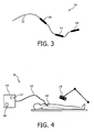
- FIG. 3 An embodiment of the invention is illustrated in Fig. 3 where a sensor device 50 for detecting dose of radiation received at the sensor device is schematically illustrated.
- the sensor device 50 comprises a flexible body 52 having a cross-section being comparatively small relative to the length of the device 50.
- the sensor device 50 includes cladding 54 at the flexible body 52, in this embodiment three cladding areas are illustrated, in other embodiments more or less areas may be provided.
- the cladding 54 converts incoming radiation into visible light.
- the sensor device 50 includes an optical shape sensing device disposed within the flexible body and configured to determine a shape of the flexible instrument relative to a reference, the shape sensing device configured to collect information based on its configuration to map an intraluminal structure during a procedure.
- the sensor 50 may be used in connection with an apparatus as described in relation to Fig. 1 and/or 2, e.g. the optical interrogation console 30.
- Fig. 4 schematically illustrates a radiation therapy system 56 comprising a movable radiation source 18 for directing and providing radiation to a designated target area or target volume 60.
- An elongated flexible instrument 62 is provided.
- the elongated flexible instrument 62 is of the type described in relation to Fig. 3 and comprise any features mentioned in relation to the discussed presented there.
- the sensor 62 is connected to an optical system 64 similar to the optical interrogation console 30 described above.
- the system 64 comprises a detector 67 that is connected to the sensor device for detecting the visible light. In this way, the detector is able to determine the dose of radiation received at the sensor device.
- the system 64 further comprises a processor 66 for performing the mentioned method steps described later.
- the processor 66 is configured or adapted to operating the movable radiation source 18 in relation to the predetermined target radiation dose and the determined dose of radiation.
- the processor may be configured or adapted via a software product implementing the steps of the method according to the present invention.
- the processor may in some embodiments be constituted by several processors, where one processor is configured or adapted to operate the radiation therapy part and another processor is adapted to perform measurements. Further the processor 66 is used for directing the radiation to the designated target area or volume 60 as the patient moves, e.g. breathes. This is done in response to the position determination of the fiber as described elsewhere.
- optical shape sensing utilizes special optical fibers which are integrated in a catheter or device and connected to an analysis unit outside the body of the patient. The position and the shape of the fiber is measured in real time using modeling and analysis of the optical Rayleigh scattering with respect to the analysis unit attached to one end of the device.
- one or more additional optical fibers are added which have a scintillating cladding at one or a number of distances along the device, which is illustrated e.g. in Fig. 3 .
- the scintillating claddings may be optimized for different energies of the incoming radiation, e.g. for diagnostic X-ray energies or for photon energies used in radiation therapy. They convert the incoming photons into visible light and therefore, they allow quantification of the radiation reaching different areas of the catheter or its tip.
- the device i.e. the elongated flexible instrument
- the elongated flexible instrument may advantageously be used as follows:
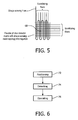
- a scintillating fiber dosimeter array 68 can be built having an interweaved shape sensing fiber or scintillating shape sensing fiber. This setup allows for a belt-type device or similar body/organ contour conforming matrix / flexible sensor array which can track organ deformation as well as locally applied dose for external beam radiation therapy.
- Fig. 6 schematically illustrates steps of an embodiment of a method 70 of operating a radiation therapy system
- a movable radiation source for directing and providing radiation to a designated target area or target volume
- an elongated flexible instrument comprising a sensor device detecting dose of radiation received at the sensor device, the sensor device including a cladding converting incoming radiation into visible light, an optical shape sensing device disposed within the flexible instrument and configured to determine a shape of the flexible instrument relative to a reference, the shape sensing device configured to collect information based on its configuration to map an intraluminal structure during a procedure, a detector connected to the sensor device for detecting the visible light so as to determine the dose of radiation received at the sensor device, and a processor for operating the movable radiation source in relation to a predetermined target radiation dose and the determined dose of radiation, the method comprising the steps positioning 72 the movable radiation source so as to direct and provide radiation to the designated target area or target volume, detecting 74 the dose of radiation received at the sensor device, and operating 76 the
- the method is preferably computer implemented and may include steps of operating any features of the system described in relation to Fig. 1 or 2 and/or using the device described in relation to Fig. 3 or 5 .
- Fig. 7 schematically illustrates a sensor device 80 having a configurable volume, here in the form of a balloon 82, in a relaxed state.
- the balloon 82 may be packed into a catheter when being inserted through the body of a patient and then be deployed to the state illustrated in Fig. 7 .
- a number of dose sensors 84 In the balloon 82, or on the surface thereof, is mounted a number of dose sensors 84.
- Fig. 8 schematically illustrates the sensor device 80 having a configurable volume, i.e. the balloon 82, in an engage state.
- the configurable volume may be engaged by use of an inert gas or the like.
Landscapes
- Health & Medical Sciences (AREA)
- Life Sciences & Earth Sciences (AREA)
- Engineering & Computer Science (AREA)
- Biomedical Technology (AREA)
- Physics & Mathematics (AREA)
- General Health & Medical Sciences (AREA)
- Nuclear Medicine, Radiotherapy & Molecular Imaging (AREA)
- High Energy & Nuclear Physics (AREA)
- Medical Informatics (AREA)
- Molecular Biology (AREA)
- Pathology (AREA)
- Radiology & Medical Imaging (AREA)
- Animal Behavior & Ethology (AREA)
- Public Health (AREA)
- Veterinary Medicine (AREA)
- General Physics & Mathematics (AREA)
- Spectroscopy & Molecular Physics (AREA)
- Optics & Photonics (AREA)
- Biophysics (AREA)
- Heart & Thoracic Surgery (AREA)
- Surgery (AREA)
- Radiation-Therapy Devices (AREA)
- Measurement Of Radiation (AREA)
Claims (15)
- Sensorvorrichtung (50, 80) zum Detektieren der an der Sensorvorrichtung (50, 80) empfangenen Strahlendosis, wobei die Sensorvorrichtung (50, 80) Folgendes umfasst:einen flexiblen Körper (52) mit einem Querschnitt, der im Vergleich zu der Länge der Vorrichtung relativ klein ist,eine Verkleidung (54, 84) an dem flexiblen Körper (52), wobei die Verkleidung die eintreffende Strahlung in sichtbares Licht umwandelt, gekennzeichnet durcheine optische Formsensorvorrichtung (20), die innerhalb des flexiblen Körpers angeordnet ist und dafür eingerichtet ist, eine Form der Sensorvorrichtung (50, 80) relativ zu einer Referenz zu ermitteln, wobei die Formsensorvorrichtung dafür eingerichtet ist, Informationen basierend auf ihrer Konfiguration zu erfassen, um eine intraluminale Struktur während einer Prozedur abzubilden.
- Sensorvorrichtung (50, 80) nach Anspruch 1, wobei die Verkleidung (54, 84) eine szintillierende Verkleidung ist.
- Sensorvorrichtung (50, 80) nach Anspruch 1, die weiterhin ein konfigurierbares Volumen (82) mit einer Verkleidung (54, 84) umfasst.
- Sensorvorrichtung (50, 80) nach Anspruch 3, wobei das konfigurierbare Volumen (82) mithilfe eines einsetzbaren Ballons, einer Korbvorrichtung, einer Filtervorrichtung, einer Helix oder einer Kombination hiervon geschaffen wird.
- Strahlentherapiesystem (56) mit einer Sensorvorrichtung (50, 80) nach Anspruch 1, wobei das Strahlentherapiesystem weiterhin Folgendes umfasst:eine bewegliche Strahlungsquelle (18) zum Lenken und Liefern einer Strahlung an einen bestimmten Zielbereich oder ein bestimmtes Zielvolumen (60),einen mit der Sensorvorrichtung verbundenen Detektor (67) zum Detektieren des sichtbaren Lichts, um so die an der Sensorvorrichtung empfangene Strahlendosis zu ermitteln,einen Prozessor (66) zum Betreiben der beweglichen Strahlungsquelle (18) in Bezug auf eine vorgegebene Zielstrahlendosis und die ermittelte Strahlendosis.
- Strahlentherapiesystem nach Anspruch 5, wobei die Verkleidung (54, 84) eine szintillierende Verkleidung ist.
- Strahlentherapiesystem nach Anspruch 5, wobei die Sensorvorrichtung (50, 80) mehrere Verkleidungsbereiche (54, 84) umfasst, die über die Länge der Sensorvorrichtung (50, 80) verteilt sind.
- Strahlentherapiesystem nach Anspruch 5, wobei die Sensorvorrichtung (50, 80) ein konfigurierbares Volumen (82) mit einer Verkleidung umfasst.
- Strahlentherapiesystem nach Anspruch 8, wobei das konfigurierbare Volumen (82) mithilfe eines einsetzbaren Ballons, einer Korbvorrichtung, einer Filtervorrichtung, einer Helix oder einer Kombination hiervon geschaffen wird.
- Strahlentherapiesystem nach Anspruch 5, wobei die optische Formsensorvorrichtung eine optische Faser (10) mit mindestens entweder Faser-Bragg-Gittern (engl. Fiber Bragg Gratings, FBGs) und/oder einer Konfiguration zur Abfrage der Rayleigh-Streuung zum Messen der Dehnung in der Faser umfasst.
- Strahlentherapiesystem nach Anspruch 5, wobei die optische Formsensorvorrichtung einen Bereich höherer Empfindlichkeit umfasst, indem sie einen Bereich mit einer höheren Anzahl an optischen Faser mit optischen Dehnungssensoren umfasst.
- Strahlentherapiesystem nach Anspruch 5, wobei die optische Formsensorvorrichtung entweder eine Spiralform, eine Ringform, eine gerade oder gekrümmte Linie und/oder eine Schleifenform umfasst.
- Verfahren zum Betreiben eines Strahlentherapiesystems (56) mit einer beweglichen Strahlungsquelle (18) zum Lenken und Liefern einer Strahlung an einen bestimmten Zielbereich oder ein bestimmtes Zielvolumen (60), einem länglichen flexiblen Instrument (50, 80) mit einer Sensorvorrichtung zum Detektieren der an der Sensorvorrichtung empfangenen Strahlendosis, wobei die Sensorvorrichtung Folgendes umfasst: eine Verkleidung (54, 84), die eintreffende Strahlung in sichtbares Licht umwandelt, eine optischen Formsensorvorrichtung, die innerhalb des flexiblen Instruments (50, 80) angeordnet ist und dafür eingerichtet ist, eine Form des flexiblen Instruments relativ zu einer Referenz zu ermitteln, wobei die Formsensorvorrichtung dafür eingerichtet ist, Informationen basierend auf ihrer Konfiguration zu erfassen, um während einer Prozedur eine intraluminale Struktur abzubilden, einen mit der Sensorvorrichtung verbundenen Detektor zum Detektieren des sichtbaren Lichts, um so die an der Sensorvorrichtung empfangene Strahlendosis zu ermitteln, und einen Prozessor (66) zum Betreiben der beweglichen Strahlungsquelle (18) in Bezug auf eine vorgegebene Zielstrahlendosis und die ermittelte Strahlendosis, wobei das Verfahren die folgenden Schritte umfasst:Positionieren (72) der beweglichen Strahlungsquelle (18), um Strahlung auf einen bestimmten Zielbereich oder ein bestimmtes Zielvolumen (60) zu lenken und an diesen Zielbereich oder dieses Zielvolumen zu liefern,Detektieren (74) der an der Sensorvorrichtung empfangenen Strahlendosis, undBetreiben (76) der beweglichen Strahlungsquelle (18) in Reaktion auf die detektierte empfangene Strahlendosis.
- Verfahren nach Anspruch 13, wobei die Position der Sensorvorrichtung unter Verwendung der optischen Rayleigh-Streuung ermittelt wird.
- Verfahren nach Anspruch 13, das weiterhin Folgendes umfasst:Ermitteln der Orientierung des länglichen flexiblen Elements unter Verwendung der optischen Formsensorvorrichtung.
Applications Claiming Priority (2)
| Application Number | Priority Date | Filing Date | Title |
|---|---|---|---|
| US201161556315P | 2011-11-07 | 2011-11-07 | |
| PCT/IB2012/055968 WO2013068877A2 (en) | 2011-11-07 | 2012-10-29 | Flexible x-ray, detector with optical shape sensing |
Publications (2)
| Publication Number | Publication Date |
|---|---|
| EP2751592A2 EP2751592A2 (de) | 2014-07-09 |
| EP2751592B1 true EP2751592B1 (de) | 2015-08-05 |
Family
ID=47520162
Family Applications (1)
| Application Number | Title | Priority Date | Filing Date |
|---|---|---|---|
| EP12812343.7A Not-in-force EP2751592B1 (de) | 2011-11-07 | 2012-10-29 | Flexibler röntgenstrahldetektor mit optischer formmessung |
Country Status (8)
| Country | Link |
|---|---|
| US (1) | US9987503B2 (de) |
| EP (1) | EP2751592B1 (de) |
| JP (1) | JP6149040B2 (de) |
| CN (1) | CN103917894B (de) |
| IN (1) | IN2014CN03975A (de) |
| MX (1) | MX2014005377A (de) |
| RU (1) | RU2014123202A (de) |
| WO (1) | WO2013068877A2 (de) |
Cited By (1)
| Publication number | Priority date | Publication date | Assignee | Title |
|---|---|---|---|---|
| EP4121799A4 (de) * | 2020-03-19 | 2024-04-24 | Duke University | Lokalisierte strahlungsmessung und meldung von oberflächen |
Families Citing this family (13)
| Publication number | Priority date | Publication date | Assignee | Title |
|---|---|---|---|---|
| WO2013144736A1 (en) * | 2012-03-26 | 2013-10-03 | Koninklijke Philips N.V. | System for planning radiation treatment therapy |
| EP2847651A1 (de) * | 2012-05-10 | 2015-03-18 | Koninklijke Philips N.V. | Gestensteuerung |
| EP2979113A4 (de) * | 2013-03-28 | 2016-11-30 | Atomic Energy Of Canada Ltd Énergie Atomique Du Canada Limitée | System und verfahren zur dreidimensionalen echtzeit-dosimetrie |
| JP6535020B2 (ja) * | 2014-03-02 | 2019-06-26 | ブイ.ティー.エム.(バーチャル テープ メジャー)テクノロジーズ リミテッド | 内視鏡画像内で可視の物体の3d距離および寸法を測定するシステム |
| WO2016038492A1 (en) * | 2014-09-08 | 2016-03-17 | Koninklijke Philips N.V. | Detection of surface contact with optical shape sensing |
| GB2532090A (en) * | 2014-11-10 | 2016-05-11 | Dosevue Nv | System and methods for distributed dosimetry on a single light guide |
| WO2017045963A1 (en) | 2015-09-16 | 2017-03-23 | Koninklijke Philips N.V. | Medical system using optical shape sensing fiber for triggering an event |
| DE102016123846A1 (de) * | 2016-12-08 | 2018-06-14 | Visus Health It Gmbh | Detektorband für Röntgenfilm |
| CN108535765A (zh) * | 2018-04-20 | 2018-09-14 | 南开大学 | 一种基于闪烁光纤的辐射成像装置及其实现方法 |
| CN109724778B (zh) * | 2019-01-14 | 2020-09-04 | 武汉理工大学 | 基于三芯光纤扭曲补偿的三维位姿恢复方法 |
| FR3094889B1 (fr) * | 2019-04-12 | 2022-08-19 | Quantum Surgical | Dispositif et procédé de contrôle de la respiration d’un patient pour un robot médical |
| US20240027633A1 (en) * | 2022-07-22 | 2024-01-25 | University Of Utah Research Foundation | Dose monitor for flash radiotherapy |
| EP4407350A1 (de) * | 2023-01-27 | 2024-07-31 | Fraunhofer-Gesellschaft zur Förderung der angewandten Forschung e.V. | Strahlungsdetektor und verfahren zu seiner verwendung |
Citations (2)
| Publication number | Priority date | Publication date | Assignee | Title |
|---|---|---|---|---|
| US7791046B2 (en) * | 2008-05-20 | 2010-09-07 | The Charles Stark Draper Laboratory, Inc. | High efficiency fiber-optic scintillator radiation detector |
| WO2011098926A1 (en) * | 2010-02-09 | 2011-08-18 | Koninklijke Philips Electronics N.V. | Apparatus, system and method for imaging and treatment using optical position sensing |
Family Cites Families (16)
| Publication number | Priority date | Publication date | Assignee | Title |
|---|---|---|---|---|
| US5088492A (en) | 1987-09-16 | 1992-02-18 | Olympus Optical Co., Ltd. | Radioactive ray detecting endoscope |
| US5793046A (en) * | 1996-10-23 | 1998-08-11 | Mcdermott Technology, Inc. | Active cladding scintillating-fiber radiation detector |
| US6514277B1 (en) | 1999-06-11 | 2003-02-04 | Photonics Research Ontario | Fiber optic multitasking probe |
| US6612992B1 (en) | 2000-03-02 | 2003-09-02 | Acuson Corp | Medical diagnostic ultrasound catheter and method for position determination |
| US6846286B2 (en) | 2001-05-22 | 2005-01-25 | Pentax Corporation | Endoscope system |
| JP2003098259A (ja) | 2001-09-27 | 2003-04-03 | Nihon Medi Physics Co Ltd | 放射線検出器 |
| JP2004251779A (ja) | 2003-02-20 | 2004-09-09 | Fuji Photo Optical Co Ltd | 長尺可撓部材の三次元形状検出装置 |
| US7297154B2 (en) * | 2003-02-24 | 2007-11-20 | Maxwell Sensors Inc. | Optical apparatus for detecting and treating vulnerable plaque |
| DE102004008373B3 (de) * | 2004-02-20 | 2005-09-29 | Siemens Ag | Vorrichtung zum Durchführen und Überwachen der endovaskulären Brachytherapie |
| JP4288351B2 (ja) | 2004-12-08 | 2009-07-01 | 国立大学法人 筑波大学 | 放射線照射時における標的臓器と線量分布の同時測定システム |
| US8568285B2 (en) | 2005-12-05 | 2013-10-29 | Hampton University | Apparatus and method for external beam radiation distribution mapping |
| US8989528B2 (en) | 2006-02-22 | 2015-03-24 | Hansen Medical, Inc. | Optical fiber grating sensors and methods of manufacture |
| US9186046B2 (en) | 2007-08-14 | 2015-11-17 | Koninklijke Philips Electronics N.V. | Robotic instrument systems and methods utilizing optical fiber sensor |
| EP2024761B1 (de) | 2006-05-16 | 2014-05-07 | SurgicEye GmbH | Verfahren und einrichtung zur 3d-beschaffung, 3d-visualisierung und computergeführten chirurgie unter verwendung von nuklearsonden |
| US7831016B2 (en) | 2007-03-01 | 2010-11-09 | Best Medical Canada | Radiation dosimetry apparatus and method, and dosimeter for use therein |
| JP2009045432A (ja) | 2007-07-26 | 2009-03-05 | Fujifilm Corp | 放射線画像撮影方法、並びにこの放射線画像撮影方法を実行する放射線画像撮影システム及び放射線情報システム |
-
2012
- 2012-10-29 JP JP2014539444A patent/JP6149040B2/ja not_active Expired - Fee Related
- 2012-10-29 US US14/356,188 patent/US9987503B2/en not_active Expired - Fee Related
- 2012-10-29 MX MX2014005377A patent/MX2014005377A/es active IP Right Grant
- 2012-10-29 IN IN3975CHN2014 patent/IN2014CN03975A/en unknown
- 2012-10-29 EP EP12812343.7A patent/EP2751592B1/de not_active Not-in-force
- 2012-10-29 WO PCT/IB2012/055968 patent/WO2013068877A2/en active Application Filing
- 2012-10-29 RU RU2014123202/28A patent/RU2014123202A/ru not_active Application Discontinuation
- 2012-10-29 CN CN201280054600.5A patent/CN103917894B/zh not_active Expired - Fee Related
Patent Citations (2)
| Publication number | Priority date | Publication date | Assignee | Title |
|---|---|---|---|---|
| US7791046B2 (en) * | 2008-05-20 | 2010-09-07 | The Charles Stark Draper Laboratory, Inc. | High efficiency fiber-optic scintillator radiation detector |
| WO2011098926A1 (en) * | 2010-02-09 | 2011-08-18 | Koninklijke Philips Electronics N.V. | Apparatus, system and method for imaging and treatment using optical position sensing |
Cited By (1)
| Publication number | Priority date | Publication date | Assignee | Title |
|---|---|---|---|---|
| EP4121799A4 (de) * | 2020-03-19 | 2024-04-24 | Duke University | Lokalisierte strahlungsmessung und meldung von oberflächen |
Also Published As
| Publication number | Publication date |
|---|---|
| RU2014123202A (ru) | 2015-12-20 |
| MX2014005377A (es) | 2014-07-28 |
| WO2013068877A3 (en) | 2013-10-24 |
| JP2014532505A (ja) | 2014-12-08 |
| WO2013068877A2 (en) | 2013-05-16 |
| US9987503B2 (en) | 2018-06-05 |
| EP2751592A2 (de) | 2014-07-09 |
| US20140357988A1 (en) | 2014-12-04 |
| CN103917894A (zh) | 2014-07-09 |
| JP6149040B2 (ja) | 2017-06-14 |
| CN103917894B (zh) | 2017-04-26 |
| IN2014CN03975A (de) | 2015-09-04 |
Similar Documents
| Publication | Publication Date | Title |
|---|---|---|
| EP2751592B1 (de) | Flexibler röntgenstrahldetektor mit optischer formmessung | |
| JP6226751B2 (ja) | インターベンショナル環境内への光ファイバ形状検知の統合 | |
| CN102753092B (zh) | 用于使用光学位置感测进行成像和处置的装置和系统 | |
| EP2830502B1 (de) | Eliminierung von artefakten mittels formmessung | |
| CN103607949B (zh) | 利用光学形状感测的动态约束 | |
| CN102573691B (zh) | 用于生物物理学参数的快速分布式测量的光学感测使能的介入仪器 | |
| US10029120B2 (en) | System for planning radiation treatment therapy | |
| WO2011141829A1 (en) | Method and apparatus for dynamic tracking of medical devices using fiber bragg gratings | |
| EP2688647A1 (de) | Vorrichtung und verfahren für eine elektronische brachytherapie | |
| RU2689179C2 (ru) | Медицинский инструмент для высокодозной брахитерапии | |
| JP2015518389A5 (de) | ||
| CN103957792B (zh) | 用于内脏器官的实时机械功能评估的形状感测装置 | |
| US10952810B2 (en) | Method and system for adaptive image guided intervention | |
| CN107072558A (zh) | 成像和/或压力测量导管及其使用方法 | |
| Parent et al. | Uv exposed optical fibers with frequency domain reflectometry for device tracking in intra-arterial procedures | |
| CN115363524A (zh) | 布置在检查对象内的医学目标物和检测医学目标物的系统 |
Legal Events
| Date | Code | Title | Description |
|---|---|---|---|
| PUAI | Public reference made under article 153(3) epc to a published international application that has entered the european phase |
Free format text: ORIGINAL CODE: 0009012 |
|
| 17P | Request for examination filed |
Effective date: 20140331 |
|
| AK | Designated contracting states |
Kind code of ref document: A2 Designated state(s): AL AT BE BG CH CY CZ DE DK EE ES FI FR GB GR HR HU IE IS IT LI LT LU LV MC MK MT NL NO PL PT RO RS SE SI SK SM TR |
|
| 17Q | First examination report despatched |
Effective date: 20141118 |
|
| DAX | Request for extension of the european patent (deleted) | ||
| GRAP | Despatch of communication of intention to grant a patent |
Free format text: ORIGINAL CODE: EPIDOSNIGR1 |
|
| INTG | Intention to grant announced |
Effective date: 20150217 |
|
| GRAS | Grant fee paid |
Free format text: ORIGINAL CODE: EPIDOSNIGR3 |
|
| GRAA | (expected) grant |
Free format text: ORIGINAL CODE: 0009210 |
|
| AK | Designated contracting states |
Kind code of ref document: B1 Designated state(s): AL AT BE BG CH CY CZ DE DK EE ES FI FR GB GR HR HU IE IS IT LI LT LU LV MC MK MT NL NO PL PT RO RS SE SI SK SM TR |
|
| REG | Reference to a national code |
Ref country code: GB Ref legal event code: FG4D |
|
| REG | Reference to a national code |
Ref country code: CH Ref legal event code: EP |
|
| REG | Reference to a national code |
Ref country code: AT Ref legal event code: REF Ref document number: 741024 Country of ref document: AT Kind code of ref document: T Effective date: 20150815 |
|
| REG | Reference to a national code |
Ref country code: IE Ref legal event code: FG4D |
|
| REG | Reference to a national code |
Ref country code: DE Ref legal event code: R096 Ref document number: 602012009416 Country of ref document: DE |
|
| REG | Reference to a national code |
Ref country code: FR Ref legal event code: PLFP Year of fee payment: 4 |
|
| REG | Reference to a national code |
Ref country code: AT Ref legal event code: MK05 Ref document number: 741024 Country of ref document: AT Kind code of ref document: T Effective date: 20150805 |
|
| REG | Reference to a national code |
Ref country code: LT Ref legal event code: MG4D |
|
| REG | Reference to a national code |
Ref country code: NL Ref legal event code: MP Effective date: 20150805 |
|
| PG25 | Lapsed in a contracting state [announced via postgrant information from national office to epo] |
Ref country code: GR Free format text: LAPSE BECAUSE OF FAILURE TO SUBMIT A TRANSLATION OF THE DESCRIPTION OR TO PAY THE FEE WITHIN THE PRESCRIBED TIME-LIMIT Effective date: 20151106 Ref country code: FI Free format text: LAPSE BECAUSE OF FAILURE TO SUBMIT A TRANSLATION OF THE DESCRIPTION OR TO PAY THE FEE WITHIN THE PRESCRIBED TIME-LIMIT Effective date: 20150805 Ref country code: NO Free format text: LAPSE BECAUSE OF FAILURE TO SUBMIT A TRANSLATION OF THE DESCRIPTION OR TO PAY THE FEE WITHIN THE PRESCRIBED TIME-LIMIT Effective date: 20151105 Ref country code: LT Free format text: LAPSE BECAUSE OF FAILURE TO SUBMIT A TRANSLATION OF THE DESCRIPTION OR TO PAY THE FEE WITHIN THE PRESCRIBED TIME-LIMIT Effective date: 20150805 Ref country code: LV Free format text: LAPSE BECAUSE OF FAILURE TO SUBMIT A TRANSLATION OF THE DESCRIPTION OR TO PAY THE FEE WITHIN THE PRESCRIBED TIME-LIMIT Effective date: 20150805 |
|
| PG25 | Lapsed in a contracting state [announced via postgrant information from national office to epo] |
Ref country code: PL Free format text: LAPSE BECAUSE OF FAILURE TO SUBMIT A TRANSLATION OF THE DESCRIPTION OR TO PAY THE FEE WITHIN THE PRESCRIBED TIME-LIMIT Effective date: 20150805 Ref country code: RS Free format text: LAPSE BECAUSE OF FAILURE TO SUBMIT A TRANSLATION OF THE DESCRIPTION OR TO PAY THE FEE WITHIN THE PRESCRIBED TIME-LIMIT Effective date: 20150805 Ref country code: AT Free format text: LAPSE BECAUSE OF FAILURE TO SUBMIT A TRANSLATION OF THE DESCRIPTION OR TO PAY THE FEE WITHIN THE PRESCRIBED TIME-LIMIT Effective date: 20150805 Ref country code: ES Free format text: LAPSE BECAUSE OF FAILURE TO SUBMIT A TRANSLATION OF THE DESCRIPTION OR TO PAY THE FEE WITHIN THE PRESCRIBED TIME-LIMIT Effective date: 20150805 Ref country code: IS Free format text: LAPSE BECAUSE OF FAILURE TO SUBMIT A TRANSLATION OF THE DESCRIPTION OR TO PAY THE FEE WITHIN THE PRESCRIBED TIME-LIMIT Effective date: 20151205 Ref country code: HR Free format text: LAPSE BECAUSE OF FAILURE TO SUBMIT A TRANSLATION OF THE DESCRIPTION OR TO PAY THE FEE WITHIN THE PRESCRIBED TIME-LIMIT Effective date: 20150805 Ref country code: PT Free format text: LAPSE BECAUSE OF FAILURE TO SUBMIT A TRANSLATION OF THE DESCRIPTION OR TO PAY THE FEE WITHIN THE PRESCRIBED TIME-LIMIT Effective date: 20151207 Ref country code: SE Free format text: LAPSE BECAUSE OF FAILURE TO SUBMIT A TRANSLATION OF THE DESCRIPTION OR TO PAY THE FEE WITHIN THE PRESCRIBED TIME-LIMIT Effective date: 20150805 |
|
| PG25 | Lapsed in a contracting state [announced via postgrant information from national office to epo] |
Ref country code: NL Free format text: LAPSE BECAUSE OF FAILURE TO SUBMIT A TRANSLATION OF THE DESCRIPTION OR TO PAY THE FEE WITHIN THE PRESCRIBED TIME-LIMIT Effective date: 20150805 |
|
| PG25 | Lapsed in a contracting state [announced via postgrant information from national office to epo] |
Ref country code: EE Free format text: LAPSE BECAUSE OF FAILURE TO SUBMIT A TRANSLATION OF THE DESCRIPTION OR TO PAY THE FEE WITHIN THE PRESCRIBED TIME-LIMIT Effective date: 20150805 Ref country code: SK Free format text: LAPSE BECAUSE OF FAILURE TO SUBMIT A TRANSLATION OF THE DESCRIPTION OR TO PAY THE FEE WITHIN THE PRESCRIBED TIME-LIMIT Effective date: 20150805 Ref country code: DK Free format text: LAPSE BECAUSE OF FAILURE TO SUBMIT A TRANSLATION OF THE DESCRIPTION OR TO PAY THE FEE WITHIN THE PRESCRIBED TIME-LIMIT Effective date: 20150805 Ref country code: CZ Free format text: LAPSE BECAUSE OF FAILURE TO SUBMIT A TRANSLATION OF THE DESCRIPTION OR TO PAY THE FEE WITHIN THE PRESCRIBED TIME-LIMIT Effective date: 20150805 Ref country code: IT Free format text: LAPSE BECAUSE OF FAILURE TO SUBMIT A TRANSLATION OF THE DESCRIPTION OR TO PAY THE FEE WITHIN THE PRESCRIBED TIME-LIMIT Effective date: 20150805 |
|
| REG | Reference to a national code |
Ref country code: DE Ref legal event code: R097 Ref document number: 602012009416 Country of ref document: DE |
|
| PG25 | Lapsed in a contracting state [announced via postgrant information from national office to epo] |
Ref country code: RO Free format text: LAPSE BECAUSE OF FAILURE TO SUBMIT A TRANSLATION OF THE DESCRIPTION OR TO PAY THE FEE WITHIN THE PRESCRIBED TIME-LIMIT Effective date: 20150805 Ref country code: LU Free format text: LAPSE BECAUSE OF FAILURE TO SUBMIT A TRANSLATION OF THE DESCRIPTION OR TO PAY THE FEE WITHIN THE PRESCRIBED TIME-LIMIT Effective date: 20151029 |
|
| REG | Reference to a national code |
Ref country code: CH Ref legal event code: PL |
|
| PLBE | No opposition filed within time limit |
Free format text: ORIGINAL CODE: 0009261 |
|
| STAA | Information on the status of an ep patent application or granted ep patent |
Free format text: STATUS: NO OPPOSITION FILED WITHIN TIME LIMIT |
|
| PG25 | Lapsed in a contracting state [announced via postgrant information from national office to epo] |
Ref country code: MC Free format text: LAPSE BECAUSE OF FAILURE TO SUBMIT A TRANSLATION OF THE DESCRIPTION OR TO PAY THE FEE WITHIN THE PRESCRIBED TIME-LIMIT Effective date: 20150805 |
|
| 26N | No opposition filed |
Effective date: 20160509 |
|
| REG | Reference to a national code |
Ref country code: IE Ref legal event code: MM4A |
|
| PG25 | Lapsed in a contracting state [announced via postgrant information from national office to epo] |
Ref country code: LI Free format text: LAPSE BECAUSE OF NON-PAYMENT OF DUE FEES Effective date: 20151031 Ref country code: CH Free format text: LAPSE BECAUSE OF NON-PAYMENT OF DUE FEES Effective date: 20151031 |
|
| PG25 | Lapsed in a contracting state [announced via postgrant information from national office to epo] |
Ref country code: SI Free format text: LAPSE BECAUSE OF FAILURE TO SUBMIT A TRANSLATION OF THE DESCRIPTION OR TO PAY THE FEE WITHIN THE PRESCRIBED TIME-LIMIT Effective date: 20150805 |
|
| REG | Reference to a national code |
Ref country code: FR Ref legal event code: PLFP Year of fee payment: 5 |
|
| PG25 | Lapsed in a contracting state [announced via postgrant information from national office to epo] |
Ref country code: IE Free format text: LAPSE BECAUSE OF NON-PAYMENT OF DUE FEES Effective date: 20151029 |
|
| PG25 | Lapsed in a contracting state [announced via postgrant information from national office to epo] |
Ref country code: BE Free format text: LAPSE BECAUSE OF FAILURE TO SUBMIT A TRANSLATION OF THE DESCRIPTION OR TO PAY THE FEE WITHIN THE PRESCRIBED TIME-LIMIT Effective date: 20150805 |
|
| PG25 | Lapsed in a contracting state [announced via postgrant information from national office to epo] |
Ref country code: BG Free format text: LAPSE BECAUSE OF FAILURE TO SUBMIT A TRANSLATION OF THE DESCRIPTION OR TO PAY THE FEE WITHIN THE PRESCRIBED TIME-LIMIT Effective date: 20150805 Ref country code: SM Free format text: LAPSE BECAUSE OF FAILURE TO SUBMIT A TRANSLATION OF THE DESCRIPTION OR TO PAY THE FEE WITHIN THE PRESCRIBED TIME-LIMIT Effective date: 20150805 Ref country code: HU Free format text: LAPSE BECAUSE OF FAILURE TO SUBMIT A TRANSLATION OF THE DESCRIPTION OR TO PAY THE FEE WITHIN THE PRESCRIBED TIME-LIMIT; INVALID AB INITIO Effective date: 20121029 |
|
| GBPC | Gb: european patent ceased through non-payment of renewal fee |
Effective date: 20161029 |
|
| PG25 | Lapsed in a contracting state [announced via postgrant information from national office to epo] |
Ref country code: CY Free format text: LAPSE BECAUSE OF FAILURE TO SUBMIT A TRANSLATION OF THE DESCRIPTION OR TO PAY THE FEE WITHIN THE PRESCRIBED TIME-LIMIT Effective date: 20150805 |
|
| PG25 | Lapsed in a contracting state [announced via postgrant information from national office to epo] |
Ref country code: GB Free format text: LAPSE BECAUSE OF NON-PAYMENT OF DUE FEES Effective date: 20161029 |
|
| PG25 | Lapsed in a contracting state [announced via postgrant information from national office to epo] |
Ref country code: MT Free format text: LAPSE BECAUSE OF FAILURE TO SUBMIT A TRANSLATION OF THE DESCRIPTION OR TO PAY THE FEE WITHIN THE PRESCRIBED TIME-LIMIT Effective date: 20150805 |
|
| REG | Reference to a national code |
Ref country code: FR Ref legal event code: PLFP Year of fee payment: 6 |
|
| REG | Reference to a national code |
Ref country code: DE Ref legal event code: R082 Ref document number: 602012009416 Country of ref document: DE Representative=s name: MEISSNER BOLTE PATENTANWAELTE RECHTSANWAELTE P, DE Ref country code: DE Ref legal event code: R081 Ref document number: 602012009416 Country of ref document: DE Owner name: PHILIPS GMBH, DE Free format text: FORMER OWNER: PHILIPS DEUTSCHLAND GMBH, 20099 HAMBURG, DE |
|
| PG25 | Lapsed in a contracting state [announced via postgrant information from national office to epo] |
Ref country code: MK Free format text: LAPSE BECAUSE OF FAILURE TO SUBMIT A TRANSLATION OF THE DESCRIPTION OR TO PAY THE FEE WITHIN THE PRESCRIBED TIME-LIMIT Effective date: 20150805 |
|
| REG | Reference to a national code |
Ref country code: FR Ref legal event code: PLFP Year of fee payment: 7 |
|
| PG25 | Lapsed in a contracting state [announced via postgrant information from national office to epo] |
Ref country code: AL Free format text: LAPSE BECAUSE OF FAILURE TO SUBMIT A TRANSLATION OF THE DESCRIPTION OR TO PAY THE FEE WITHIN THE PRESCRIBED TIME-LIMIT Effective date: 20150805 Ref country code: TR Free format text: LAPSE BECAUSE OF FAILURE TO SUBMIT A TRANSLATION OF THE DESCRIPTION OR TO PAY THE FEE WITHIN THE PRESCRIBED TIME-LIMIT Effective date: 20150805 |
|
| PGFP | Annual fee paid to national office [announced via postgrant information from national office to epo] |
Ref country code: DE Payment date: 20191129 Year of fee payment: 8 |
|
| PGFP | Annual fee paid to national office [announced via postgrant information from national office to epo] |
Ref country code: FR Payment date: 20191025 Year of fee payment: 8 |
|
| REG | Reference to a national code |
Ref country code: DE Ref legal event code: R119 Ref document number: 602012009416 Country of ref document: DE |
|
| PG25 | Lapsed in a contracting state [announced via postgrant information from national office to epo] |
Ref country code: FR Free format text: LAPSE BECAUSE OF NON-PAYMENT OF DUE FEES Effective date: 20201031 Ref country code: DE Free format text: LAPSE BECAUSE OF NON-PAYMENT OF DUE FEES Effective date: 20210501 |