EP2749938A1 - Array substrate for display device - Google Patents
Array substrate for display device Download PDFInfo
- Publication number
- EP2749938A1 EP2749938A1 EP13197360.4A EP13197360A EP2749938A1 EP 2749938 A1 EP2749938 A1 EP 2749938A1 EP 13197360 A EP13197360 A EP 13197360A EP 2749938 A1 EP2749938 A1 EP 2749938A1
- Authority
- EP
- European Patent Office
- Prior art keywords
- display area
- pad
- array substrate
- conductive bar
- conductive
- Prior art date
- Legal status (The legal status is an assumption and is not a legal conclusion. Google has not performed a legal analysis and makes no representation as to the accuracy of the status listed.)
- Granted
Links
Images


Classifications
-
- G—PHYSICS
- G09—EDUCATION; CRYPTOGRAPHY; DISPLAY; ADVERTISING; SEALS
- G09F—DISPLAYING; ADVERTISING; SIGNS; LABELS OR NAME-PLATES; SEALS
- G09F9/00—Indicating arrangements for variable information in which the information is built-up on a support by selection or combination of individual elements
-
- G—PHYSICS
- G02—OPTICS
- G02F—OPTICAL DEVICES OR ARRANGEMENTS FOR THE CONTROL OF LIGHT BY MODIFICATION OF THE OPTICAL PROPERTIES OF THE MEDIA OF THE ELEMENTS INVOLVED THEREIN; NON-LINEAR OPTICS; FREQUENCY-CHANGING OF LIGHT; OPTICAL LOGIC ELEMENTS; OPTICAL ANALOGUE/DIGITAL CONVERTERS
- G02F1/00—Devices or arrangements for the control of the intensity, colour, phase, polarisation or direction of light arriving from an independent light source, e.g. switching, gating or modulating; Non-linear optics
- G02F1/01—Devices or arrangements for the control of the intensity, colour, phase, polarisation or direction of light arriving from an independent light source, e.g. switching, gating or modulating; Non-linear optics for the control of the intensity, phase, polarisation or colour
- G02F1/13—Devices or arrangements for the control of the intensity, colour, phase, polarisation or direction of light arriving from an independent light source, e.g. switching, gating or modulating; Non-linear optics for the control of the intensity, phase, polarisation or colour based on liquid crystals, e.g. single liquid crystal display cells
- G02F1/133—Constructional arrangements; Operation of liquid crystal cells; Circuit arrangements
- G02F1/13306—Circuit arrangements or driving methods for the control of single liquid crystal cells
-
- G—PHYSICS
- G02—OPTICS
- G02F—OPTICAL DEVICES OR ARRANGEMENTS FOR THE CONTROL OF LIGHT BY MODIFICATION OF THE OPTICAL PROPERTIES OF THE MEDIA OF THE ELEMENTS INVOLVED THEREIN; NON-LINEAR OPTICS; FREQUENCY-CHANGING OF LIGHT; OPTICAL LOGIC ELEMENTS; OPTICAL ANALOGUE/DIGITAL CONVERTERS
- G02F1/00—Devices or arrangements for the control of the intensity, colour, phase, polarisation or direction of light arriving from an independent light source, e.g. switching, gating or modulating; Non-linear optics
- G02F1/01—Devices or arrangements for the control of the intensity, colour, phase, polarisation or direction of light arriving from an independent light source, e.g. switching, gating or modulating; Non-linear optics for the control of the intensity, phase, polarisation or colour
- G02F1/13—Devices or arrangements for the control of the intensity, colour, phase, polarisation or direction of light arriving from an independent light source, e.g. switching, gating or modulating; Non-linear optics for the control of the intensity, phase, polarisation or colour based on liquid crystals, e.g. single liquid crystal display cells
- G02F1/133—Constructional arrangements; Operation of liquid crystal cells; Circuit arrangements
- G02F1/1333—Constructional arrangements; Manufacturing methods
- G02F1/1345—Conductors connecting electrodes to cell terminals
-
- G—PHYSICS
- G02—OPTICS
- G02F—OPTICAL DEVICES OR ARRANGEMENTS FOR THE CONTROL OF LIGHT BY MODIFICATION OF THE OPTICAL PROPERTIES OF THE MEDIA OF THE ELEMENTS INVOLVED THEREIN; NON-LINEAR OPTICS; FREQUENCY-CHANGING OF LIGHT; OPTICAL LOGIC ELEMENTS; OPTICAL ANALOGUE/DIGITAL CONVERTERS
- G02F1/00—Devices or arrangements for the control of the intensity, colour, phase, polarisation or direction of light arriving from an independent light source, e.g. switching, gating or modulating; Non-linear optics
- G02F1/01—Devices or arrangements for the control of the intensity, colour, phase, polarisation or direction of light arriving from an independent light source, e.g. switching, gating or modulating; Non-linear optics for the control of the intensity, phase, polarisation or colour
- G02F1/13—Devices or arrangements for the control of the intensity, colour, phase, polarisation or direction of light arriving from an independent light source, e.g. switching, gating or modulating; Non-linear optics for the control of the intensity, phase, polarisation or colour based on liquid crystals, e.g. single liquid crystal display cells
- G02F1/133—Constructional arrangements; Operation of liquid crystal cells; Circuit arrangements
- G02F1/1333—Constructional arrangements; Manufacturing methods
- G02F1/1345—Conductors connecting electrodes to cell terminals
- G02F1/13452—Conductors connecting driver circuitry and terminals of panels
-
- G—PHYSICS
- G02—OPTICS
- G02F—OPTICAL DEVICES OR ARRANGEMENTS FOR THE CONTROL OF LIGHT BY MODIFICATION OF THE OPTICAL PROPERTIES OF THE MEDIA OF THE ELEMENTS INVOLVED THEREIN; NON-LINEAR OPTICS; FREQUENCY-CHANGING OF LIGHT; OPTICAL LOGIC ELEMENTS; OPTICAL ANALOGUE/DIGITAL CONVERTERS
- G02F1/00—Devices or arrangements for the control of the intensity, colour, phase, polarisation or direction of light arriving from an independent light source, e.g. switching, gating or modulating; Non-linear optics
- G02F1/01—Devices or arrangements for the control of the intensity, colour, phase, polarisation or direction of light arriving from an independent light source, e.g. switching, gating or modulating; Non-linear optics for the control of the intensity, phase, polarisation or colour
- G02F1/13—Devices or arrangements for the control of the intensity, colour, phase, polarisation or direction of light arriving from an independent light source, e.g. switching, gating or modulating; Non-linear optics for the control of the intensity, phase, polarisation or colour based on liquid crystals, e.g. single liquid crystal display cells
- G02F1/133—Constructional arrangements; Operation of liquid crystal cells; Circuit arrangements
- G02F1/136—Liquid crystal cells structurally associated with a semi-conducting layer or substrate, e.g. cells forming part of an integrated circuit
- G02F1/1362—Active matrix addressed cells
- G02F1/136204—Arrangements to prevent high voltage or static electricity failures
-
- G—PHYSICS
- G02—OPTICS
- G02F—OPTICAL DEVICES OR ARRANGEMENTS FOR THE CONTROL OF LIGHT BY MODIFICATION OF THE OPTICAL PROPERTIES OF THE MEDIA OF THE ELEMENTS INVOLVED THEREIN; NON-LINEAR OPTICS; FREQUENCY-CHANGING OF LIGHT; OPTICAL LOGIC ELEMENTS; OPTICAL ANALOGUE/DIGITAL CONVERTERS
- G02F1/00—Devices or arrangements for the control of the intensity, colour, phase, polarisation or direction of light arriving from an independent light source, e.g. switching, gating or modulating; Non-linear optics
- G02F1/01—Devices or arrangements for the control of the intensity, colour, phase, polarisation or direction of light arriving from an independent light source, e.g. switching, gating or modulating; Non-linear optics for the control of the intensity, phase, polarisation or colour
- G02F1/13—Devices or arrangements for the control of the intensity, colour, phase, polarisation or direction of light arriving from an independent light source, e.g. switching, gating or modulating; Non-linear optics for the control of the intensity, phase, polarisation or colour based on liquid crystals, e.g. single liquid crystal display cells
- G02F1/133—Constructional arrangements; Operation of liquid crystal cells; Circuit arrangements
- G02F1/1333—Constructional arrangements; Manufacturing methods
- G02F1/1337—Surface-induced orientation of the liquid crystal molecules, e.g. by alignment layers
- G02F1/13378—Surface-induced orientation of the liquid crystal molecules, e.g. by alignment layers by treatment of the surface, e.g. embossing, rubbing or light irradiation
- G02F1/133784—Surface-induced orientation of the liquid crystal molecules, e.g. by alignment layers by treatment of the surface, e.g. embossing, rubbing or light irradiation by rubbing
-
- G—PHYSICS
- G02—OPTICS
- G02F—OPTICAL DEVICES OR ARRANGEMENTS FOR THE CONTROL OF LIGHT BY MODIFICATION OF THE OPTICAL PROPERTIES OF THE MEDIA OF THE ELEMENTS INVOLVED THEREIN; NON-LINEAR OPTICS; FREQUENCY-CHANGING OF LIGHT; OPTICAL LOGIC ELEMENTS; OPTICAL ANALOGUE/DIGITAL CONVERTERS
- G02F1/00—Devices or arrangements for the control of the intensity, colour, phase, polarisation or direction of light arriving from an independent light source, e.g. switching, gating or modulating; Non-linear optics
- G02F1/01—Devices or arrangements for the control of the intensity, colour, phase, polarisation or direction of light arriving from an independent light source, e.g. switching, gating or modulating; Non-linear optics for the control of the intensity, phase, polarisation or colour
- G02F1/13—Devices or arrangements for the control of the intensity, colour, phase, polarisation or direction of light arriving from an independent light source, e.g. switching, gating or modulating; Non-linear optics for the control of the intensity, phase, polarisation or colour based on liquid crystals, e.g. single liquid crystal display cells
- G02F1/133—Constructional arrangements; Operation of liquid crystal cells; Circuit arrangements
- G02F1/1333—Constructional arrangements; Manufacturing methods
- G02F1/1345—Conductors connecting electrodes to cell terminals
- G02F1/13454—Drivers integrated on the active matrix substrate
Definitions
- the present invention relates to an array substrate for a display device, and more particularly, to an array substrate for a display device including a shorting bar to prevent defects due to static electricity and a method of manufacturing the same.
- a liquid crystal display device is operated using optical anisotropy and polarization of liquid crystal.
- Molecules of the liquid crystal have a thin and long structure and have a directional alignment, and when applying electric field to the molecules, the alignment of the molecules can be controlled.
- the liquid crystal display device is manufactured by a TFT process of forming a gate line, a data line, a thin film transistor (TFT) and a pixel electrode on an array substrate, and forming a black matrix, a color filter and a common electrode on a color filter substrate, a cell process of injecting a liquid crystal between the array substrate and the color filter substrate, cutting in cell unit, and forming a unit panel, and a module process of attaching a driving IC and a printed circuit board (PCB) to the unit panel, and assembling it with a backlight unit.
- TFT thin film transistor
- the plural array substrates can be in a large-sized substrate referred to as a mother glass or an array mother glass.
- Static electricity may occur when manufacturing the mother glass and cause fatal adverse effects on elements formed at the array substrate.
- a shorting bar is formed at a peripheral portion of the mother glass and at a non-display region of each cell, which is explained as follows.
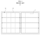
- FIG. 1 is a view illustrating the prior art mother glass
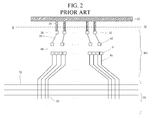
- FIG. 2 is a view enlarging a region A of FIG. 1 .
- a mother glass 10 includes a plurality of cell areas CA, each of which corresponds to an array substrate of a unit cell to be formed through post-processes.
- Size of each of the plurality of cell areas CA may be changed depending on size of the liquid crystal display device.
- FIG. 1 shows an example that 32 cells are formed in one mother glass 10.
- a shorting bar 20 is formed on the mother glass 10, and each shorting bar 20 includes a plurality of horizontal portions each formed at a boundary portion between adjacent row lines of cell areas CA, and an edge portion connecting the plurality of horizontal portions and surrounding a peripheral portion of the whole of the cell areas CA.
- Each cell area CA includes a non-display area NDA and a display area DA
- the non-display area NDA includes a FPC (flexible printed circuit) pad portion 30 and a DIC (driving integrated circuit) pad portion 40.
- the display portion DA may include a plurality of gate lines 70, a plurality of data lines 80 and electrical elements such as a plurality of thin film transistors.
- a plurality of third pads 32 are formed in the FPC pad portion 30, and a plurality of first pads 42, and a plurality of second pads 44 are formed in the DIC pad portion 40.
- the third pads 32 of the FPC pad portion 30 are portions to which a flexible printed circuit (FPC) board is attached in a later module process, and are electrically connected to the shorting bar 20 through a plurality of third link lines 25.
- FPC flexible printed circuit
- the first pads 42 and the second pads 44 of the DIC pad portion 40 are portions to which a data driving integrated circuit (IC) is attached in a later module process, and particularly, the data driving IC may be mounted in a COG (chip on glass) manner the data driving IC is directly connected to the array substrate.
- IC data driving integrated circuit
- the data driving IC functions to supply image data voltages to the display area (DA) according to a timing signal and image data signal from the outside, and in some cases, the data driving IC may generate a timing signal therein other than the timing signal from the outside and generate or supply a gate driving signal.
- the second pads 44 are connected to the display area DA through a plurality of second link lines 45, and may function to transfer the image data voltage from the data driving IC to the display area DA.
- the shorting bar 20 is formed to have a width much greater than other signal lines. Accordingly, the shorting bar 20 may function as a reservoir of charges, and charges generated by static electricity in the array substrate in processes of manufacturing the array substrate is transferred to the shorting bar 20 and discharged to an external apparatus stage or the like.
- the DIC pad portion 40 is separately configured and thus moving path of current is complicated. Accordingly, the prior art shorting bar 20 is insufficiently to completely restrain defect occurrence due to static electricity.
- the present invention is directed to an array substrate for a display device which substantially obviates one or more of the problems due to limitations and disadvantages of the prior art.
- An advantage of the present invention is to provide an array substrate for a display device that can defect due to static electricity occurring in a TFT process and a cell process.
- an array substrate for a display device includes a substrate including a display area displaying an image, and a non-display area surrounding the display area; a first pad corresponding to an input pin of a data driving IC and formed at the non-display area; a second pad corresponding to an output pin of the data driving IC and formed at the non-display area; a first conductive bar formed between the first pad and the second pad; and a second conductive bar extending from the first conductive bar to a peripheral end portion of the non-display area.
- an array substrate for a display device includes a substrate including a display area displaying an image, and a non-display area surrounding the display area; an on/off pad formed at the non-display area for application of an on/off voltage from outside the array substrate; and a conductive bar formed adjacent to the on/off pad and extending to a peripheral end portion of the non-display area.
- a method of manufacturing an array substrate comprises forming a first pad corresponding to an input pin of a data driving integrated circuit (IC), the first pad formed in a non-display area of a substrate that surrounds a display area of the substrate.
- a second pad corresponding to an output pin of the data driving IC is formed in the non-display area.
- a first conductive bar located between the first pad and the second pad and a second conductive bar extending from the first conductive bar to a peripheral end portion of the non-display area are formed.
- a rubbing process is performed on the array substrate, the rubbing process generating static electricity that is dischargeable through the first conductive bar and the second conductive bar.
- FIG. 3 is a view illustrating a mother glass including an array substrate for a display device according to an embodiment of the present invention
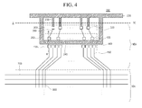
- FIG. 4 is a view enlarging a region A of FIG. 3 .
- a mother glass 100 includes a plurality of cell area CA, each of which correspond to an array substrate for a unit panel finished in a later process.
- a shorting bar 200 is formed between horizontal portions and at a peripheral portion of the mother glass 100.
- the array substrate includes a non-display area NDA and a display area DA, and the non-display area NDA includes a FPC (flexible printed circuit) pad portion 300 and a DIC (driving integrated circuit) pad portion 400.
- FPC flexible printed circuit
- DIC driving integrated circuit
- the display portion DA may include a plurality of gate lines 700, a plurality of data lines 800 and electrical elements such as a plurality of thin film transistors.
- the FPC pad portion 300 is a portion to which a flexible printed circuit board is attached in a later module process, and includes a plurality of third pads 320.
- the DIC pad portion 400 includes a plurality of first pads 420 and a plurality of second pads 440.
- the first pads 420 and the second pads 440 of the DIC pad portion 400 are portions to which a data driving IC is attached in a later module process, and particularly, a COG type driving IC is employed and mounted directly onto the array substrate.
- the first pads 420 are formed corresponding to input pins of the data driving IC, and connected to the third pads 320 through first link lines 350 to supply signals or voltages to the data driving IC.
- the second pads 440 are formed corresponding to output pins of the data driving IC, and are electrically connected to the data lines 800 through second link lines 450 to supply signals or voltages to the display area DA.
- the data driving IC functions to supply image data voltages to the display area (DA) according to a timing signal and image data signal from the outside, and in some cases, the data driving IC may generate a timing signal therein other than the timing signal from the outside and generate or supply a gate driving signal.
- the shorting bar 200 includes a plurality of conductive lines 220 formed along boundary portions between the cell areas CA, a first conductive bar 240 formed in an area of the DIC pad portion 400, and a second conductive bar 260 connecting the first conductive bar 240 and the conductive line 220.
- the conductive line 220 is electrically connected to the third pads 320 through a plurality of third link lines 250.
- the first conductive bar 240 is formed between an area of the first pads 420 and an area of the second pads 440, and is electrically insulated from the first pads 420 and the second pads 440.
- the first conductive bar 240 does not contact the input pins and the output pins of the data driving IC and thus does not influence circuit operation.
- the first conductive bar 240 may have a long rectangular shape along an arrangement direction of the first pads 420 and the second pads 440.
- the second conductive bar 260 is bent from an end of the first conductive bar 240 and extends to a peripheral portion of the non-display area NDA and is connected to the conductive line 220.
- the second conductive bar 260 may be bent from both ends of the first conductive bar 240 and extends to be connected to the conductive line 220, or may be bent from both one end of the first conductive bar 240 and extends to be connected to the conductive line 220.
- the first conductive line 240 functions as a discharge path of static electricity that occurs at the DIC pad portion 440 where the data driving IC is mounted.
- a resistance of current path through the first conductive bar 240 is less than a resistance of current path through the second pad 440.
- the line width (i.e. the width of conductive bar 240 perpendicular to the direction of static electricity current flowing out of the conductive bar 240) of the first conductive bar 240 be greater than a width of the second pad 440.
- the first conductive bar 240 may have a relatively greater width than the first and second pads 420 and 440 so long as the first conductive bar 240 does not make electrical contact with the first and second pads 420 and 440.
- the first conductive bar 240 may be formed of a material having a resistance that is less than the first and second pads 420 and 440.
- the mother substrate 100 including the plurality of array substrates each including the shorting bar 200 including the conductive line 220 and the first and second conductive bars 240 and 260 is coupled to a separate substrate including a plurality of color filter substrates with a liquid crystal between the mother substrate 100 and the separate substrate, in a later cell process.
- That structure is cut into cell units to form unit panels, and regarding the array substrate, the array substrate is cut along a scribing line SC that is defined to electrically and structurally separate the conductive line 220 from the first and second conductive bars 240 and 260.
- the scribing line SC may be defined to traverse the second conductive bar 260 and the third link line 250.
- the non-display area NDA of the array substrate finally cut includes only the first and second conductive bars 240 and 260 because the conductive line 220 is cut away.
- the scribing line SC may be defined at both of an upper portion and a lower portion with respect to the conductive line 220, and in this case, an area including the conductive line 220 is finally removed from the array substrate after the cutting process.
- the conductive line SC is not removed and remains at a lower end portion of an upper array substrate.
- the array substrate is cut to have the conductive line 220 at the lower end portion thereof, or is cut to have no conductive line 220.
- the flexible printed circuit board and the data driving circuit are attached to the unit panel and a module process of assembling them with a backlight unit is performed.
- FIG. 5 is a view illustrating a mother glass including an array substrate for a display device according to another embodiment of the present invention
- FIG. 6 is a view enlarging a region A of FIG. 5 .
- the another embodiment includes the same as the FPC pad portion 300, the DIC pad portion 400, the conductive line 220 and the first and second conductive bars 240 and 260 of the first embodiment, and explanations of the components are omitted.
- the array substrate may include on/off pads 600 for test in the non-display area NDA.
- the on/off pads 600 may be used in a test process that checks defect of the panel before and after the cell process. Various external voltage signals are applied by a test apparatus or worker, and thus the defect of the panel may be checked.
- a clock signal is input to a gate driving circuit built in the array substrate through the on/off pad 600, and a test image voltage is input to each data line 800 through the on/off pad 600. Accordingly, even though operation is not performed with a real data driving IC mounted, whether the defect or no can be sensed in advance.
- selective signals to control the demultiplexers 500 in the test process may be supplied through the on/off pads 600.
- Each demultiplexer 500 makes 1:N connections of second pad 440 to data lines 800 and is connected to the second pad 440 through the second link line 450. Accordingly, each channel of the data driving IC can be connected to a plurality of data lines 800 and operation of time division can be performed for the data lines 800, and thus a number of channels of the data driving IC can be reduced.
- the demultiplexer 500 includes at least two switch elements, and the switch elements are controlled by a select control signal and thus one out ofN data lines 800 is selected.
- the select control signal may be supplied through the FPC pad portion 300 from the outside, and in case that the data driving IC supplies a timing control signal to operate the display area DA, the select control signal may be supplied from the data driving IC.
- the select control signal may be supplied through the on/off pads 600 from the outside in the test process, and supplied to the demultiplexers 500 through select control signal supply lines 520 connected to the on/off pads 600.
- the shorting bar 200 includes the conductive line 220 and the first and second conductive bars 240 and 260, as shown in FIGs. 3 and 4 , and further includes a third conductive bar 280.
- the third conductive bar 280 is adjacent to the on/off pads 600 and prevents defects that static electricity occurring in a cell process or the like causes by flowing into the on/off pad 600 and damaging internal circuitry. Particularly, static electricity is prone to occur because of friction between an area of the on/off pad 600 and a rubbing cloth in a rubbing process of a cell process.
- the static electricity is lead to the third conductive bar 280 rather than the on/off pad 600 and is discharged to the outside through the conductive line 220.
- the third conductive bar 280 may be formed to be in a rectangular shape and large such that it corresponds to an area where the on/off pads 600 are formed. In order to increase current inflow effect, the third conductive bar 280 may be formed to surround the on/off pads 600 such that it corresponds to a side surface of the on/off pads 600.
- the mother substrate 100 including the plurality of array substrates each including the shorting bar 200 including the conductive line 220 and the first to third conductive bars 240, 260 and 280 is coupled to a separate substrate including a plurality of color filter substrates with a liquid crystal between the mother substrate 100 and the separate substrate, in a later cell process.
- That structure is cut into cell units to form unit panels, and regarding the array substrate, the array substrate is cut along a scribing line SC that is defined to electrically and structurally separate the conductive line 220 from the first to third conductive bars 240, 260 and 280.
- the scribing line SC may be defined to traverse the second and third conductive bars 260 and 280 and the third link line 250.
- the non-display area NDA of the array substrate finally cut includes only the first to third conductive bars 240, 260 and 280 because the conductive line 220 is cut away.
- the flexible printed circuit board and the data driving IC are attached to the unit panel and a module process of assembling them with a backlight unit is performed.
- the third conductive bar 280 is formed along with the first and second conductive bars 240 and 260, but it is not required. For example, in order to prevent static electricity flowing through the on/off pads 600, only the third conductive bar 280 is formed without the first and second bars 240 and 260.
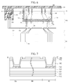
- FIG. 7 is a cross-sectional view taken along a line B-B' of the DIC pad portion of FIG. 6 .
- FIG. 7 shows a substrate where a semiconductor layer of a thin film transistor is formed of polysilicon, but it is not required.
- the semiconductor layer may be formed of amorphous silicon or oxide semiconductor.
- the array substrate where the semiconductor layer is formed of polysilicon is explained as below.
- a buffer layer 120 made of inorganic insulating material is formed on a transparent substrate 110 made of glass or etc.
- the buffer layer 120 is configured to prevent property reduction of a thin film transistor that occurs because a semiconductor layer is influenced by alkali ions emitted from the substrate 110.
- a gate insulating layer 130 is formed on the buffer layer 120.
- a semiconductor layer is formed between the process of forming the buffer layer 120 and the process of forming the gate insulating layer 130.
- the semiconductor layer is etched and removed in area other than the display area DA in a mask process of forming the semiconductor layer, it is shown that the gate insulating layer 130 is formed on the buffer layer 120 without the semiconductor layer therebetween in the non-display area NDA.
- the gate insulating layer 130 in the display area DA functions to insulate the semiconductor layer from a metal layer for a gate electrode and a gate line formed in a later process.
- the metal layer for the gate electrode and the gate line may be etched and removed in area other than an area of thin film transistor of the display area DA in a mask process of forming the gate electrode and the gate line. Accordingly, in the area of B-B' of the DIC pad portion 400, an interlayer insulating film 140 is formed without the metal layer.
- the metal layer for the gate electrode and the gate line may be formed by depositing at least one of molybdenum (Mo), titanium (Ti), tantalum (Ta), tungsten (W), copper (Cu), chrome (Cr), aluminum (Al), an alloy from combination thereof, indium tin oxide, and indium zinc oxide.
- Mo molybdenum
- Ti titanium
- Ta tantalum
- Cu copper
- Cr chrome
- Al aluminum
- the interlayer insulating film 140 is formed on the gate insulating layer 130.
- the interlayer insulating film 140 in the display area DA functions to insulate the metal layer for the gate electrode and the gate line from a data line layer 150 formed in a later process.
- the data line layer 150 in the display area DA may function as source/drain of the thin film transistor and a line supplying an image data voltage to the thin film transistor, and the data line layer 150 in the non-display area NDA may directly contact a transparent conductive layer 180, as shown in the cross-sectional view of the line B-B' of the DIC pad portion 400, and may function to be applied with the image data voltage supplied from a pad layer and supply the image data voltage to the inside of the panel.
- the metal layer for the data line layer 150 may be formed by depositing at least of one molybdenum (Mo), titanium (Ti), tantalum (Ta), tungsten (W), copper (Cu), chrome (Cr), aluminum (Al), an alloy from combination thereof, indium tin oxide, and indium zinc oxide.
- Mo molybdenum
- Ti titanium
- Ta tantalum
- Cu copper
- Cr chrome
- Al aluminum
- a first passivation layer 160 is formed on the data line layer 150.
- the first passivation layer 160 may be formed of an organic film, for example, polyimide, benzocyclobutene series resin, or acrylate.
- the first passivation layer 160 may have a lamination structure of inorganic film and organic film, or a lamination structure of at least two organic films.
- a second passivation layer 170 may be formed on the first passivation layer 160, and may be formed of an inorganic film using at least one of silicon oxide film, a silicon nitride film and a silicate film.
- a transparent conductive layer 180 is formed on the second passivation layer 170.
- the transparent conductive layer 180 may be formed of at least one of indium tin oxide, indium zinc oxide and indium tin zinc oxide.
- the transparent conductive layer 180 in the display area DA may function as a pixel electrode or common electrode, and the transparent conductive layer 180 in the non-display area NDA may function as a pad, which directly contacts the flexible printed circuit board or an input/output pin of the data driving IC, in order to be supplied from the outside.
- the transparent conductive layer 180 contacts the data line layer 150 through a contact hole in the first and second passivation layers 160 and 170.
- An area BA is a cross section for the first pad 420 of the DIC pad portion 400.
- the transparent conductive layer 180 of the first pad 420 contacts an input pin of the data driving IC, and functions to supply a timing signal and a data image signal supplied through the data line layer 150 to the data driving IC.
- An area BC is a cross section for the second pad 440 of the DIC pad portion 400.
- the transparent conductive layer 180 of the second pad 440 contacts an output pin of the data driving IC, and functions to supply a timing signal or a data image voltage supplied from the data driving IC through the data line layer 150 to the display area DA.
- An area BB is a cross section for the first conductive bar 240 of the shorting bar 200.
- the first conductive bar 240 includes the transparent conductive layer 180 and is separated and insulated from the transparent conductive layer 180 of the first and second pads 420 and 440 by a mask process.
- the conductive line 220 and the second and third conductive bars 260 and 280 forming the shorting bar 200 other than the first conductive bar 240 have substantially the same cross section of the first conductive bar 240, and are connected to one another through the transparent conductive layer.
- a line width of the first conductive bar 240 of the area BB is greater than line width of the first and second pads 420 and 440 of the areas BA and BC. Accordingly, in case that static electricity occurs, the static electricity moves to the first conductive bar 240 rather than the first and second pads 420 and 440, and thus damage on inter circuit due to the static electricity can be prevented.
- a display device using the DIC pad portion 400 of the non-display area NDA can be used, for example, in an organic electroluminescent display device or the like.
- the array substrate of the display device includes the first conductive bar formed between the input and output pads of the data driving IC and the second conductive bar extending from the end portion of the first conductive bar to the peripheral end portion. Accordingly, defects of the electrical elements of the array substrate due to static electricity that occur in a rubbing process and the like can be prevented.
Landscapes
- Physics & Mathematics (AREA)
- Nonlinear Science (AREA)
- General Physics & Mathematics (AREA)
- Mathematical Physics (AREA)
- Chemical & Material Sciences (AREA)
- Crystallography & Structural Chemistry (AREA)
- Optics & Photonics (AREA)
- Engineering & Computer Science (AREA)
- Microelectronics & Electronic Packaging (AREA)
- Theoretical Computer Science (AREA)
- Devices For Indicating Variable Information By Combining Individual Elements (AREA)
- Liquid Crystal (AREA)
Abstract
Description
- The present invention claims the benefit of Korean Patent Application No.
10-2012-0154240 - The present invention relates to an array substrate for a display device, and more particularly, to an array substrate for a display device including a shorting bar to prevent defects due to static electricity and a method of manufacturing the same.
- Generally, a liquid crystal display device is operated using optical anisotropy and polarization of liquid crystal. Molecules of the liquid crystal have a thin and long structure and have a directional alignment, and when applying electric field to the molecules, the alignment of the molecules can be controlled.
- In other words, when the alignment direction of the liquid crystal molecules is changed using an electric field, light is refracted in the aligned direction due to the optical anisotropy and thus images can be displayed.
- The liquid crystal display device is manufactured by a TFT process of forming a gate line, a data line, a thin film transistor (TFT) and a pixel electrode on an array substrate, and forming a black matrix, a color filter and a common electrode on a color filter substrate, a cell process of injecting a liquid crystal between the array substrate and the color filter substrate, cutting in cell unit, and forming a unit panel, and a module process of attaching a driving IC and a printed circuit board (PCB) to the unit panel, and assembling it with a backlight unit.
- The plural array substrates can be in a large-sized substrate referred to as a mother glass or an array mother glass.
- Static electricity may occur when manufacturing the mother glass and cause fatal adverse effects on elements formed at the array substrate.
- For example, when an insulating layer between two conductive lines is electrically broken down by strong static electricity, the two conductive lines are short-circuited and thus the liquid crystal display device is not normally operated.
- To prevent the short circuit and degradation of the elements due to the static electricity, a shorting bar is formed at a peripheral portion of the mother glass and at a non-display region of each cell, which is explained as follows.
-
FIG. 1 is a view illustrating the prior art mother glass, andFIG. 2 is a view enlarging a region A ofFIG. 1 . - Referring to
FIGs. 1 and2 , amother glass 10 includes a plurality of cell areas CA, each of which corresponds to an array substrate of a unit cell to be formed through post-processes. - Size of each of the plurality of cell areas CA may be changed depending on size of the liquid crystal display device.
FIG. 1 shows an example that 32 cells are formed in onemother glass 10. - A
shorting bar 20 is formed on themother glass 10, and each shortingbar 20 includes a plurality of horizontal portions each formed at a boundary portion between adjacent row lines of cell areas CA, and an edge portion connecting the plurality of horizontal portions and surrounding a peripheral portion of the whole of the cell areas CA. - Each cell area CA includes a non-display area NDA and a display area DA, and the non-display area NDA includes a FPC (flexible printed circuit)
pad portion 30 and a DIC (driving integrated circuit)pad portion 40. - The display portion DA may include a plurality of
gate lines 70, a plurality ofdata lines 80 and electrical elements such as a plurality of thin film transistors. - A plurality of
third pads 32 are formed in theFPC pad portion 30, and a plurality offirst pads 42, and a plurality ofsecond pads 44 are formed in theDIC pad portion 40. - The
third pads 32 of theFPC pad portion 30 are portions to which a flexible printed circuit (FPC) board is attached in a later module process, and are electrically connected to theshorting bar 20 through a plurality ofthird link lines 25. - The
first pads 42 and thesecond pads 44 of theDIC pad portion 40 are portions to which a data driving integrated circuit (IC) is attached in a later module process, and particularly, the data driving IC may be mounted in a COG (chip on glass) manner the data driving IC is directly connected to the array substrate. - The data driving IC functions to supply image data voltages to the display area (DA) according to a timing signal and image data signal from the outside, and in some cases, the data driving IC may generate a timing signal therein other than the timing signal from the outside and generate or supply a gate driving signal.
- The
second pads 44 are connected to the display area DA through a plurality ofsecond link lines 45, and may function to transfer the image data voltage from the data driving IC to the display area DA. - The shorting
bar 20 is formed to have a width much greater than other signal lines. Accordingly, the shortingbar 20 may function as a reservoir of charges, and charges generated by static electricity in the array substrate in processes of manufacturing the array substrate is transferred to the shortingbar 20 and discharged to an external apparatus stage or the like. - However, even though the
shorting bar 20 is configured, internal circuit is prone to be damaged because of static electricity occurring in the cell process. - Particularly, when coating an alignment layer on the array substrate and conducting a rubbing process, static electricity is prone to occur because of direct friction between a rubbing cloth and signal line/pad portion on the non-display area NDA where the alignment layer is not coated. Accordingly, damage to circuit portion occurs because of movement of charge inside the display area DA.
- Particularly, in case of the COG type driving IC, the
DIC pad portion 40 is separately configured and thus moving path of current is complicated. Accordingly, the priorart shorting bar 20 is insufficiently to completely restrain defect occurrence due to static electricity. - Accordingly, the present invention is directed to an array substrate for a display device which substantially obviates one or more of the problems due to limitations and disadvantages of the prior art.
- An advantage of the present invention is to provide an array substrate for a display device that can defect due to static electricity occurring in a TFT process and a cell process.
- Additional features and advantages of the present invention will be set forth in the description which follows, and in part will be apparent from the description, or may be learned by practice of the invention. These and other advantages of the invention will be realized and attained by the structure particularly pointed out in the written description and claims thereof as well as the appended drawings.
- To achieve these and other advantages and in accordance with the purpose of the present invention, as embodied and broadly described herein, an array substrate for a display device includes a substrate including a display area displaying an image, and a non-display area surrounding the display area; a first pad corresponding to an input pin of a data driving IC and formed at the non-display area; a second pad corresponding to an output pin of the data driving IC and formed at the non-display area; a first conductive bar formed between the first pad and the second pad; and a second conductive bar extending from the first conductive bar to a peripheral end portion of the non-display area.
- In another aspect, an array substrate for a display device includes a substrate including a display area displaying an image, and a non-display area surrounding the display area; an on/off pad formed at the non-display area for application of an on/off voltage from outside the array substrate; and a conductive bar formed adjacent to the on/off pad and extending to a peripheral end portion of the non-display area.
- In another embodiment, a method of manufacturing an array substrate is disclosed. The method comprises forming a first pad corresponding to an input pin of a data driving integrated circuit (IC), the first pad formed in a non-display area of a substrate that surrounds a display area of the substrate. A second pad corresponding to an output pin of the data driving IC is formed in the non-display area. A first conductive bar located between the first pad and the second pad and a second conductive bar extending from the first conductive bar to a peripheral end portion of the non-display area are formed. A rubbing process is performed on the array substrate, the rubbing process generating static electricity that is dischargeable through the first conductive bar and the second conductive bar.
- The accompanying drawings, which are included to provide a further understanding of the invention and are incorporated in and constitute a part of this specification, illustrate embodiments of the invention and together with the description serve to explain the principles of the invention.
- In the drawings:
-
FIG. 1 is a view illustrating the prior art mother glass; -
FIG. 2 is a view enlarging a region A ofFIG. 1 ; -
FIG. 3 is a view illustrating a mother glass including an array substrate for a display device according to an embodiment of the present invention; -
FIG. 4 is a view enlarging a region A ofFIG. 3 ; -
FIG. 5 is a view illustrating a mother glass including an array substrate for a display device according to another embodiment of the present invention; -
FIG. 6 is a view enlarging a region A ofFIG. 5 ; and -
FIG. 7 is a cross-sectional view taken along a line B-B' of the DIC pad portion ofFIG. 6 . - Reference will now be made in detail to the illustrated embodiments of the present invention, which are illustrated in the accompanying drawings.
-
FIG. 3 is a view illustrating a mother glass including an array substrate for a display device according to an embodiment of the present invention, andFIG. 4 is a view enlarging a region A ofFIG. 3 . - Referring to
FIGs. 3 and4 , amother glass 100 includes a plurality of cell area CA, each of which correspond to an array substrate for a unit panel finished in a later process. - A
shorting bar 200 is formed between horizontal portions and at a peripheral portion of themother glass 100. - The array substrate includes a non-display area NDA and a display area DA, and the non-display area NDA includes a FPC (flexible printed circuit)
pad portion 300 and a DIC (driving integrated circuit)pad portion 400. - The display portion DA may include a plurality of
gate lines 700, a plurality ofdata lines 800 and electrical elements such as a plurality of thin film transistors. - The
FPC pad portion 300 is a portion to which a flexible printed circuit board is attached in a later module process, and includes a plurality ofthird pads 320. - The
DIC pad portion 400 includes a plurality offirst pads 420 and a plurality ofsecond pads 440. - The
first pads 420 and thesecond pads 440 of theDIC pad portion 400 are portions to which a data driving IC is attached in a later module process, and particularly, a COG type driving IC is employed and mounted directly onto the array substrate. - The
first pads 420 are formed corresponding to input pins of the data driving IC, and connected to thethird pads 320 throughfirst link lines 350 to supply signals or voltages to the data driving IC. - The
second pads 440 are formed corresponding to output pins of the data driving IC, and are electrically connected to thedata lines 800 throughsecond link lines 450 to supply signals or voltages to the display area DA. - The data driving IC functions to supply image data voltages to the display area (DA) according to a timing signal and image data signal from the outside, and in some cases, the data driving IC may generate a timing signal therein other than the timing signal from the outside and generate or supply a gate driving signal.
- The shorting
bar 200 includes a plurality ofconductive lines 220 formed along boundary portions between the cell areas CA, a firstconductive bar 240 formed in an area of theDIC pad portion 400, and a secondconductive bar 260 connecting the firstconductive bar 240 and theconductive line 220. - The
conductive line 220 is electrically connected to thethird pads 320 through a plurality of third link lines 250. - The first
conductive bar 240 is formed between an area of thefirst pads 420 and an area of thesecond pads 440, and is electrically insulated from thefirst pads 420 and thesecond pads 440. - Even though the data driving IC is mounted in a later module process, the first
conductive bar 240 does not contact the input pins and the output pins of the data driving IC and thus does not influence circuit operation. - The first
conductive bar 240 may have a long rectangular shape along an arrangement direction of thefirst pads 420 and thesecond pads 440. - The second
conductive bar 260 is bent from an end of the firstconductive bar 240 and extends to a peripheral portion of the non-display area NDA and is connected to theconductive line 220. - As the second
conductive bar 260 functions to electrically connect the firstconductive bar 220 to theconductive line 220, the secondconductive bar 260 may be bent from both ends of the firstconductive bar 240 and extends to be connected to theconductive line 220, or may be bent from both one end of the firstconductive bar 240 and extends to be connected to theconductive line 220. - The first
conductive line 240 functions as a discharge path of static electricity that occurs at theDIC pad portion 440 where the data driving IC is mounted. - Particularly, in a rubbing process of a cell process, static electricity is prone to occur because of friction between pads and lines in an area of the
DIC pad portion 440 and a rubbing cloth, and as such the static electricity is lead to the firstconductive bar 240 rather than to a pad or line and is discharged to the outside through the secondconductive bar 260 and theconductive line 220. - If the static electricity is lead to the display area DA through the
second pad 440 and not through the firstconductive bar 240, the thin film transistors in the display area DA may be damaged. Accordingly, in order for the static electricity to move through the firstconductive bar 240, it is preferred that a resistance of current path through the firstconductive bar 240 is less than a resistance of current path through thesecond pad 440. - To do this, it is preferred that the line width (i.e. the width of
conductive bar 240 perpendicular to the direction of static electricity current flowing out of the conductive bar 240) of the firstconductive bar 240 be greater than a width of thesecond pad 440. The firstconductive bar 240 may have a relatively greater width than the first andsecond pads conductive bar 240 does not make electrical contact with the first andsecond pads - Moreover, the first
conductive bar 240 may be formed of a material having a resistance that is less than the first andsecond pads - The
mother substrate 100 including the plurality of array substrates each including the shortingbar 200 including theconductive line 220 and the first and secondconductive bars mother substrate 100 and the separate substrate, in a later cell process. - That structure is cut into cell units to form unit panels, and regarding the array substrate, the array substrate is cut along a scribing line SC that is defined to electrically and structurally separate the
conductive line 220 from the first and secondconductive bars conductive bar 260 and thethird link line 250. - Accordingly, the non-display area NDA of the array substrate finally cut includes only the first and second
conductive bars conductive line 220 is cut away. - The scribing line SC may be defined at both of an upper portion and a lower portion with respect to the
conductive line 220, and in this case, an area including theconductive line 220 is finally removed from the array substrate after the cutting process. - In case that the scribing line SC is defined only at a lower portion with respect to the
conductive line 220, the conductive line is not removed and remains at a lower end portion of an upper array substrate. - Accordingly, according to the definition of the scribing line SC, the array substrate is cut to have the
conductive line 220 at the lower end portion thereof, or is cut to have noconductive line 220. - Then, the flexible printed circuit board and the data driving circuit are attached to the unit panel and a module process of assembling them with a backlight unit is performed.
-
FIG. 5 is a view illustrating a mother glass including an array substrate for a display device according to another embodiment of the present invention, andFIG. 6 is a view enlarging a region A ofFIG. 5 . - The another embodiment includes the same as the
FPC pad portion 300, theDIC pad portion 400, theconductive line 220 and the first and secondconductive bars - The array substrate may include on/off
pads 600 for test in the non-display area NDA. - The on/off
pads 600 may be used in a test process that checks defect of the panel before and after the cell process. Various external voltage signals are applied by a test apparatus or worker, and thus the defect of the panel may be checked. - For example, a clock signal is input to a gate driving circuit built in the array substrate through the on/off
pad 600, and a test image voltage is input to eachdata line 800 through the on/offpad 600. Accordingly, even though operation is not performed with a real data driving IC mounted, whether the defect or no can be sensed in advance. - Moreover, in case that a plurality of
demultiplexers 500 are formed on the array substrate, selective signals to control thedemultiplexers 500 in the test process may be supplied through the on/offpads 600. - Each
demultiplexer 500 makes 1:N connections ofsecond pad 440 todata lines 800 and is connected to thesecond pad 440 through thesecond link line 450. Accordingly, each channel of the data driving IC can be connected to a plurality ofdata lines 800 and operation of time division can be performed for thedata lines 800, and thus a number of channels of the data driving IC can be reduced. - The
demultiplexer 500 includes at least two switch elements, and the switch elements are controlled by a select control signal and thus one outofN data lines 800 is selected. - The select control signal may be supplied through the
FPC pad portion 300 from the outside, and in case that the data driving IC supplies a timing control signal to operate the display area DA, the select control signal may be supplied from the data driving IC. - The select control signal may be supplied through the on/off
pads 600 from the outside in the test process, and supplied to thedemultiplexers 500 through select controlsignal supply lines 520 connected to the on/offpads 600. - The shorting
bar 200 includes theconductive line 220 and the first and secondconductive bars FIGs. 3 and4 , and further includes a thirdconductive bar 280. - The third
conductive bar 280 is adjacent to the on/offpads 600 and prevents defects that static electricity occurring in a cell process or the like causes by flowing into the on/offpad 600 and damaging internal circuitry. Particularly, static electricity is prone to occur because of friction between an area of the on/offpad 600 and a rubbing cloth in a rubbing process of a cell process. The static electricity is lead to the thirdconductive bar 280 rather than the on/offpad 600 and is discharged to the outside through theconductive line 220. - The third
conductive bar 280 may be formed to be in a rectangular shape and large such that it corresponds to an area where the on/offpads 600 are formed. In order to increase current inflow effect, the thirdconductive bar 280 may be formed to surround the on/offpads 600 such that it corresponds to a side surface of the on/offpads 600. - The
mother substrate 100 including the plurality of array substrates each including the shortingbar 200 including theconductive line 220 and the first to thirdconductive bars mother substrate 100 and the separate substrate, in a later cell process. - That structure is cut into cell units to form unit panels, and regarding the array substrate, the array substrate is cut along a scribing line SC that is defined to electrically and structurally separate the
conductive line 220 from the first to thirdconductive bars conductive bars third link line 250. - Accordingly, the non-display area NDA of the array substrate finally cut includes only the first to third
conductive bars conductive line 220 is cut away. - Then, the flexible printed circuit board and the data driving IC are attached to the unit panel and a module process of assembling them with a backlight unit is performed.
- It is described above that the third
conductive bar 280 is formed along with the first and secondconductive bars pads 600, only the thirdconductive bar 280 is formed without the first andsecond bars -
FIG. 7 is a cross-sectional view taken along a line B-B' of the DIC pad portion ofFIG. 6 . -
FIG. 7 shows a substrate where a semiconductor layer of a thin film transistor is formed of polysilicon, but it is not required. The semiconductor layer may be formed of amorphous silicon or oxide semiconductor. For the purpose of explanations, the array substrate where the semiconductor layer is formed of polysilicon is explained as below. - Referring to
FIG. 7 , abuffer layer 120 made of inorganic insulating material is formed on atransparent substrate 110 made of glass or etc. - The
buffer layer 120 is configured to prevent property reduction of a thin film transistor that occurs because a semiconductor layer is influenced by alkali ions emitted from thesubstrate 110. - A
gate insulating layer 130 is formed on thebuffer layer 120. In the manufacturing processes, a semiconductor layer is formed between the process of forming thebuffer layer 120 and the process of forming thegate insulating layer 130. However, since the semiconductor layer is etched and removed in area other than the display area DA in a mask process of forming the semiconductor layer, it is shown that thegate insulating layer 130 is formed on thebuffer layer 120 without the semiconductor layer therebetween in the non-display area NDA. - The
gate insulating layer 130 in the display area DA functions to insulate the semiconductor layer from a metal layer for a gate electrode and a gate line formed in a later process. - The metal layer for the gate electrode and the gate line may be etched and removed in area other than an area of thin film transistor of the display area DA in a mask process of forming the gate electrode and the gate line. Accordingly, in the area of B-B' of the
DIC pad portion 400, aninterlayer insulating film 140 is formed without the metal layer. - The metal layer for the gate electrode and the gate line may be formed by depositing at least one of molybdenum (Mo), titanium (Ti), tantalum (Ta), tungsten (W), copper (Cu), chrome (Cr), aluminum (Al), an alloy from combination thereof, indium tin oxide, and indium zinc oxide.
- The
interlayer insulating film 140 is formed on thegate insulating layer 130. Theinterlayer insulating film 140 in the display area DA functions to insulate the metal layer for the gate electrode and the gate line from adata line layer 150 formed in a later process. - The
data line layer 150 in the display area DA may function as source/drain of the thin film transistor and a line supplying an image data voltage to the thin film transistor, and thedata line layer 150 in the non-display area NDA may directly contact a transparentconductive layer 180, as shown in the cross-sectional view of the line B-B' of theDIC pad portion 400, and may function to be applied with the image data voltage supplied from a pad layer and supply the image data voltage to the inside of the panel. - The metal layer for the
data line layer 150 may be formed by depositing at least of one molybdenum (Mo), titanium (Ti), tantalum (Ta), tungsten (W), copper (Cu), chrome (Cr), aluminum (Al), an alloy from combination thereof, indium tin oxide, and indium zinc oxide. - A
first passivation layer 160 is formed on thedata line layer 150. Thefirst passivation layer 160 may be formed of an organic film, for example, polyimide, benzocyclobutene series resin, or acrylate. - Alternatively, the
first passivation layer 160 may have a lamination structure of inorganic film and organic film, or a lamination structure of at least two organic films. - A
second passivation layer 170 may be formed on thefirst passivation layer 160, and may be formed of an inorganic film using at least one of silicon oxide film, a silicon nitride film and a silicate film. - A transparent
conductive layer 180 is formed on thesecond passivation layer 170. The transparent conductive layer 180may be formed of at least one of indium tin oxide, indium zinc oxide and indium tin zinc oxide. - The transparent
conductive layer 180 in the display area DA may function as a pixel electrode or common electrode, and the transparentconductive layer 180 in the non-display area NDA may function as a pad, which directly contacts the flexible printed circuit board or an input/output pin of the data driving IC, in order to be supplied from the outside. - To do this, the transparent
conductive layer 180 contacts thedata line layer 150 through a contact hole in the first and second passivation layers 160 and 170. - An area BA is a cross section for the
first pad 420 of theDIC pad portion 400. The transparentconductive layer 180 of thefirst pad 420 contacts an input pin of the data driving IC, and functions to supply a timing signal and a data image signal supplied through thedata line layer 150 to the data driving IC. - An area BC is a cross section for the
second pad 440 of theDIC pad portion 400. The transparentconductive layer 180 of thesecond pad 440 contacts an output pin of the data driving IC, and functions to supply a timing signal or a data image voltage supplied from the data driving IC through thedata line layer 150 to the display area DA. - An area BB is a cross section for the first
conductive bar 240 of the shortingbar 200. The firstconductive bar 240 includes the transparentconductive layer 180 and is separated and insulated from the transparentconductive layer 180 of the first andsecond pads - Even though not shown entirely, the
conductive line 220 and the second and thirdconductive bars bar 200 other than the firstconductive bar 240 have substantially the same cross section of the firstconductive bar 240, and are connected to one another through the transparent conductive layer. - A line width of the first
conductive bar 240 of the area BB is greater than line width of the first andsecond pads conductive bar 240 rather than the first andsecond pads - In the present invention, an example using the liquid crystal display device is explained, but it is not required. A display device using the
DIC pad portion 400 of the non-display area NDA can be used, for example, in an organic electroluminescent display device or the like. - As described above, the array substrate of the display device according to the embodiment of the present invention includes the first conductive bar formed between the input and output pads of the data driving IC and the second conductive bar extending from the end portion of the first conductive bar to the peripheral end portion. Accordingly, defects of the electrical elements of the array substrate due to static electricity that occur in a rubbing process and the like can be prevented.
- It will be apparent to those skilled in the art that various modifications and variations can be made in the present invention without departing from the spirit or scope of the invention. Thus, it is intended that the present invention cover the modifications and variations of this invention provided they come within the scope of the appended claims and their equivalents.
Claims (20)
- An array substrate for a display device comprising:a substrate including a display area for displaying an image, and a non-display area surrounding the display area;a first pad corresponding to an input pin of a data driving integrated circuit (IC) and formed at the non-display area;a second pad corresponding to an output pin of the data driving IC and formed at the non-display area;a first conductive bar formed between the first pad and the second pad; anda second conductive bar extending from the first conductive bar to a peripheral end portion of the non-display area.
- The array substrate according to claim 1, wherein the first and second conductive bars are formed of a same material as the first and second pads.
- The array substrate according to claim 1, wherein a line width of the first conductive bar is greater than a width of the second pad.
- The array substrate according to claim 1, wherein the first and second conductive bars each includes:a gate insulating layer on the substrate;a passivation layer on the gate insulating layer; anda transparent conductive layer on the passivation layer.
- The array substrate according to claim 4, wherein the transparent conductive layer is comprised of indium tin oxide or indium zinc oxide.
- The array substrate according to claim 1, further comprising:an on/off pad formed at the non-display area for application of an on/off voltage from outside the array substrate; anda third conductive bar formed adjacent to the on/off pad and extending to the peripheral end portion of the non-display area.
- The array substrate according to claim 6, wherein the third conductive bar has a rectangular shape corresponding to an area where the on/off pad is formed.
- The array substrate according to claim 6, wherein the third conductive bar is formed to surround at least a part of an area where the on/off pad is formed.
- The array substrate according to claim 6, wherein the display area includes: a gate line; a data line crossing the gate line to define a pixel region; and a thin film transistor connected to the gate line and the data line,
wherein the array substrate includes a demultiplexer that is formed at the non-display area and between the second pad and the data line, and includes at least two switch elements to selectively supply an image data voltage from the data driving IC to the data line according to a select control signal, and
wherein the select control signal is supplied to the demultiplexer through the on/off pad. - The array substrate according to claim 6, wherein the third conductive bar is formed of a same material as the second conductive bar.
- The array substrate according to claim 1, wherein the second conductive bar extends from an end portion of the first conductive bar to a peripheral end portion of the non-display area
- An array substrate for a display device comprising:a substrate including a display area for displaying an image, and a non-display area surrounding the display area;an on/off pad formed at the non-display area for application of an on/off voltage from outside the array substrate; anda conductive bar formed adjacent to the on/off pad and extending to a peripheral end portion of the non-display area.
- The array substrate according to claim 12, wherein the display area includes: a gate line; a data line crossing the gate line to define a pixel region; and a thin film transistor connected to the gate line and the data line,
wherein the array substrate includes a demultiplexer that is formed at the non-display area, and selectively supplies an image data voltage to the data line according to a select control signal, and
wherein the select control signal is supplied to the demultiplexer through the on/off pad. - The array substrate according to claim 12, wherein the conductive bar has a rectangular shape corresponding to an area where the on/off pad is formed.
- The array substrate according to claim 12, wherein the conductive bar is formed to surround at least a part of an area where the on/off pad is formed.
- A method of manufacturing an array substrate, the method comprising:forming a first pad corresponding to an input pin of a data driving integrated circuit (IC), the first pad formed in a non-display area of a substrate that surrounds a display area of the substrate;forming a second pad corresponding to an output pin of the data driving IC, the second pad formed in the non-display area;forming a first conductive bar located between the first pad and the second pad and a second conductive bar extending from the first conductive bar to a peripheral end portion of the non-display area; andperforming a rubbing process on the array substrate, static electricity generated from the rubbing process being dischargable through the first conductive bar and the second conductive bar.
- The method of claim 16, wherein the first conductive bar is formed to have a line width that is greater than a width of the second pad.
- The method of claim 16, further comprising:forming an on/off pad for application of an on/off voltage from outside the array substrate, the on/off pad formed in the non-display area; andforming a third conductive bar adjacent to the on/off pad and extending to the peripheral end portion of the non-display area, the static electricity generated during the rubbing process being further dischargeable through the third conductive bar.
- The method of claim 16, wherein the second conductive bar is formed to extend from an end portion of the first conductive bar to a peripheral end portion of the non-display area.
- The method of claim 16, further comprising:forming a conductive line electrically connected to the second conductive bar, the static electricity generated during the rubbing process being further dischargeable through the conductive line; andseparating the conductive line from the array substrate after performing the rubbing process.
Applications Claiming Priority (1)
| Application Number | Priority Date | Filing Date | Title |
|---|---|---|---|
| KR1020120154240A KR102107383B1 (en) | 2012-12-27 | 2012-12-27 | Array substrate for display device |
Publications (2)
| Publication Number | Publication Date |
|---|---|
| EP2749938A1 true EP2749938A1 (en) | 2014-07-02 |
| EP2749938B1 EP2749938B1 (en) | 2022-03-16 |
Family
ID=49766979
Family Applications (1)
| Application Number | Title | Priority Date | Filing Date |
|---|---|---|---|
| EP13197360.4A Active EP2749938B1 (en) | 2012-12-27 | 2013-12-16 | Array substrate for display device |
Country Status (6)
| Country | Link |
|---|---|
| US (1) | US10718964B2 (en) |
| EP (1) | EP2749938B1 (en) |
| JP (1) | JP5690916B2 (en) |
| KR (1) | KR102107383B1 (en) |
| CN (1) | CN103901641B (en) |
| TW (1) | TWI582493B (en) |
Families Citing this family (35)
| Publication number | Priority date | Publication date | Assignee | Title |
|---|---|---|---|---|
| KR102140042B1 (en) * | 2014-03-27 | 2020-08-03 | 엘지디스플레이 주식회사 | Array substrate for display device |
| US10359871B2 (en) * | 2014-09-26 | 2019-07-23 | Lg Display Co., Ltd. | Display panel and method of manufacturing the same |
| KR102226240B1 (en) * | 2014-12-30 | 2021-03-10 | 엘지디스플레이 주식회사 | Display device |
| KR102166953B1 (en) * | 2014-12-30 | 2020-10-19 | 엘지디스플레이 주식회사 | Array substrate and liquid crystal display including the same |
| KR102278805B1 (en) * | 2014-12-30 | 2021-07-19 | 엘지디스플레이 주식회사 | Display device |
| KR102468366B1 (en) * | 2015-12-29 | 2022-11-18 | 엘지디스플레이 주식회사 | Organic Light Emitting Diode Display Device |
| CN105572997A (en) * | 2016-02-26 | 2016-05-11 | 武汉华星光电技术有限公司 | Display panel and signal wires thereof |
| KR102556829B1 (en) * | 2016-06-29 | 2023-07-19 | 삼성디스플레이 주식회사 | Display panel having touch functuion and display apparatus including thereof |
| KR102668848B1 (en) * | 2016-08-04 | 2024-05-24 | 삼성디스플레이 주식회사 | Liquid crystal display device |
| CN106773387B (en) * | 2016-12-28 | 2019-07-02 | 武汉华星光电技术有限公司 | The electrostatic protection structure of liquid crystal display panel |
| CN106847151B (en) | 2017-01-06 | 2019-11-19 | 昆山工研院新型平板显示技术中心有限公司 | A kind of integrated circuit and mobile phone and display |
| WO2018131649A1 (en) * | 2017-01-16 | 2018-07-19 | シャープ株式会社 | Active matrix substrate, liquid crystal display panel, and method for manufacturing liquid crystal display panel |
| TWI621900B (en) * | 2017-04-28 | 2018-04-21 | 友達光電股份有限公司 | Display device and manufacturing method thereof |
| CN107154232A (en) * | 2017-05-27 | 2017-09-12 | 厦门天马微电子有限公司 | The method of testing of array base palte, display panel and display panel |
| CN107092151B (en) * | 2017-06-30 | 2020-01-10 | 上海天马微电子有限公司 | Array substrate, electronic paper type display panel, driving method of electronic paper type display panel and display device |
| CN107290900B (en) * | 2017-08-07 | 2019-11-12 | 上海中航光电子有限公司 | a motherboard |
| US10209542B1 (en) * | 2017-12-15 | 2019-02-19 | Didrew Technology (Bvi) Limited | System and method of embedding driver IC (EmDIC) in LCD display substrate |
| CN109801909B (en) | 2018-06-12 | 2024-08-20 | 京东方科技集团股份有限公司 | Array substrate motherboard and manufacturing method thereof, array substrate, and display device |
| CN111429810B (en) * | 2019-01-09 | 2022-02-11 | 昆山工研院新型平板显示技术中心有限公司 | Stretchable device and manufacturing method thereof |
| KR102833789B1 (en) * | 2019-03-21 | 2025-07-15 | 삼성디스플레이 주식회사 | Display device and method for manufacturing the same |
| CN110097827A (en) * | 2019-04-10 | 2019-08-06 | 武汉华星光电半导体显示技术有限公司 | Display panel and display device |
| CN110187575B (en) | 2019-05-28 | 2020-12-18 | 昆山国显光电有限公司 | Array substrate and array substrate motherboard |
| CN110568655B (en) * | 2019-09-11 | 2022-10-21 | 厦门天马微电子有限公司 | Display panel and display device |
| CN112824961B (en) * | 2019-11-20 | 2024-05-31 | 元太科技工业股份有限公司 | Display device |
| TWI718772B (en) * | 2019-11-20 | 2021-02-11 | 元太科技工業股份有限公司 | Display device |
| CN110827689B (en) * | 2019-11-22 | 2023-11-03 | 昆山国显光电有限公司 | Display panel and display device |
| EP4152084A4 (en) * | 2020-05-12 | 2023-05-10 | BOE Technology Group Co., Ltd. | DISPLAY SUBSTRATE AND DISPLAY DEVICE |
| DE112020005561T5 (en) | 2020-06-30 | 2022-10-20 | Boe Technology Group Co., Ltd. | display substrate and display device |
| KR102790999B1 (en) | 2020-07-10 | 2025-04-08 | 삼성디스플레이 주식회사 | Display device |
| CN112018087B (en) * | 2020-08-13 | 2022-05-31 | 深圳市华星光电半导体显示技术有限公司 | Display panel and preparation method thereof |
| KR102741301B1 (en) * | 2020-09-28 | 2024-12-12 | 엘지디스플레이 주식회사 | Display device and driving method thereof |
| CN112526791A (en) * | 2020-11-09 | 2021-03-19 | 信利(惠州)智能显示有限公司 | Display panel and display device |
| CN112331118B (en) * | 2020-11-30 | 2023-09-26 | 武汉天马微电子有限公司 | A display panel and display device |
| KR20220106892A (en) | 2021-01-22 | 2022-08-01 | 삼성디스플레이 주식회사 | Display device |
| CN113077726B (en) * | 2021-03-23 | 2022-06-10 | 深圳市华星光电半导体显示技术有限公司 | Display panel and preparation method thereof |
Citations (3)
| Publication number | Priority date | Publication date | Assignee | Title |
|---|---|---|---|---|
| JPH0329925A (en) * | 1989-06-28 | 1991-02-07 | Hitachi Ltd | liquid crystal display device |
| US5742074A (en) * | 1995-05-31 | 1998-04-21 | Fujitsu Limited | Thin film transistor matrix device and method for fabricating the same |
| US20070268442A1 (en) * | 2006-05-19 | 2007-11-22 | Samsung Electronics Co., Ltd. | Display substrate and method of manufacturing the same and liquid crystal display apparatus having the same |
Family Cites Families (17)
| Publication number | Priority date | Publication date | Assignee | Title |
|---|---|---|---|---|
| JP3162347B2 (en) * | 1992-03-30 | 2001-04-25 | 三菱電機株式会社 | Matrix substrate for matrix type display device |
| US5949502A (en) * | 1995-08-07 | 1999-09-07 | Hitachi, Ltd. | Liquid crystal device having resistor elements |
| JP4021045B2 (en) | 1998-03-31 | 2007-12-12 | 株式会社アドバンスト・ディスプレイ | Active matrix display device |
| US6043971A (en) * | 1998-11-04 | 2000-03-28 | L.G. Philips Lcd Co., Ltd. | Electrostatic discharge protection device for liquid crystal display using a COG package |
| JP3652898B2 (en) | 1998-11-19 | 2005-05-25 | 株式会社日立製作所 | Liquid crystal display |
| JP4005410B2 (en) | 2002-05-15 | 2007-11-07 | 株式会社 日立ディスプレイズ | Image display device |
| KR100487808B1 (en) * | 2002-12-10 | 2005-05-06 | 엘지.필립스 엘시디 주식회사 | Liquid crystal display panel before grinding process and fabricating method thereof |
| JP4347581B2 (en) * | 2003-01-31 | 2009-10-21 | オプトレックス株式会社 | LCD panel |
| JP2006091239A (en) * | 2004-09-22 | 2006-04-06 | Seiko Epson Corp | Electro-optical device substrate, electro-optical device, and inspection method |
| US7710739B2 (en) * | 2005-04-28 | 2010-05-04 | Semiconductor Energy Laboratory Co., Ltd. | Semiconductor device and display device |
| JP2007219203A (en) * | 2006-02-17 | 2007-08-30 | Epson Imaging Devices Corp | Electrooptical apparatus and electronic equipment |
| JP4448834B2 (en) * | 2006-04-25 | 2010-04-14 | セイコーエプソン株式会社 | Electro-optical device and electronic apparatus including the same |
| US7760313B2 (en) * | 2006-10-02 | 2010-07-20 | Tpo Displays Corp. | System for displaying images including wiring structure for driving display panel |
| KR20090126052A (en) * | 2008-06-03 | 2009-12-08 | 삼성전자주식회사 | Thin film transistor substrate and display device therein |
| US9128568B2 (en) * | 2008-07-30 | 2015-09-08 | New Vision Display (Shenzhen) Co., Limited | Capacitive touch panel with FPC connector electrically coupled to conductive traces of face-to-face ITO pattern structure in single plane |
| KR101032440B1 (en) * | 2008-09-26 | 2011-05-03 | 엘지디스플레이 주식회사 | LCD and its manufacturing method |
| JP2010113252A (en) * | 2008-11-07 | 2010-05-20 | Epson Imaging Devices Corp | Electro-optical device and electronic apparatus provided with the same |
-
2012
- 2012-12-27 KR KR1020120154240A patent/KR102107383B1/en active Active
-
2013
- 2013-12-11 CN CN201310674760.6A patent/CN103901641B/en active Active
- 2013-12-13 US US14/106,252 patent/US10718964B2/en active Active
- 2013-12-16 EP EP13197360.4A patent/EP2749938B1/en active Active
- 2013-12-18 JP JP2013261350A patent/JP5690916B2/en active Active
- 2013-12-19 TW TW102147277A patent/TWI582493B/en not_active IP Right Cessation
Patent Citations (3)
| Publication number | Priority date | Publication date | Assignee | Title |
|---|---|---|---|---|
| JPH0329925A (en) * | 1989-06-28 | 1991-02-07 | Hitachi Ltd | liquid crystal display device |
| US5742074A (en) * | 1995-05-31 | 1998-04-21 | Fujitsu Limited | Thin film transistor matrix device and method for fabricating the same |
| US20070268442A1 (en) * | 2006-05-19 | 2007-11-22 | Samsung Electronics Co., Ltd. | Display substrate and method of manufacturing the same and liquid crystal display apparatus having the same |
Also Published As
| Publication number | Publication date |
|---|---|
| JP2014130349A (en) | 2014-07-10 |
| KR20140084601A (en) | 2014-07-07 |
| CN103901641A (en) | 2014-07-02 |
| US10718964B2 (en) | 2020-07-21 |
| EP2749938B1 (en) | 2022-03-16 |
| TWI582493B (en) | 2017-05-11 |
| TW201428385A (en) | 2014-07-16 |
| JP5690916B2 (en) | 2015-03-25 |
| CN103901641B (en) | 2017-03-01 |
| KR102107383B1 (en) | 2020-05-07 |
| US20140184989A1 (en) | 2014-07-03 |
Similar Documents
| Publication | Publication Date | Title |
|---|---|---|
| US10718964B2 (en) | Array substrate for display device | |
| US11796878B2 (en) | Active matrix substrate and display panel | |
| US7724314B2 (en) | Method for repairing a short in a substrate for a display and display repaired according to that method | |
| KR102381850B1 (en) | Display device | |
| US9443781B2 (en) | Display device | |
| US10964284B2 (en) | Electronic component board and display panel | |
| KR20090126052A (en) | Thin film transistor substrate and display device therein | |
| CN102023444B (en) | Liquid crystal display device and method of fabricating the same | |
| US10325534B2 (en) | Display device | |
| US7079199B2 (en) | Liquid crystal display panel | |
| KR20120125651A (en) | Display device | |
| WO2012090817A1 (en) | Display device and method of manufacturing same | |
| EP3021166B1 (en) | Display device and method for fabricating the same | |
| KR101710575B1 (en) | Array substrate for liquid crystal display device and method of fabricating the same | |
| KR102347412B1 (en) | Display Panel For Display Device and Test Method therefor | |
| KR20090038775A (en) | LCD and its manufacturing method | |
| KR101258085B1 (en) | Liquid crystal display device prevetable static electricity prevention and method of fabricating thereof | |
| KR101127838B1 (en) | Liquid crystal display device |
Legal Events
| Date | Code | Title | Description |
|---|---|---|---|
| 17P | Request for examination filed |
Effective date: 20140321 |
|
| AK | Designated contracting states |
Kind code of ref document: A1 Designated state(s): AL AT BE BG CH CY CZ DE DK EE ES FI FR GB GR HR HU IE IS IT LI LT LU LV MC MK MT NL NO PL PT RO RS SE SI SK SM TR |
|
| AX | Request for extension of the european patent |
Extension state: BA ME |
|
| PUAI | Public reference made under article 153(3) epc to a published international application that has entered the european phase |
Free format text: ORIGINAL CODE: 0009012 |
|
| STAA | Information on the status of an ep patent application or granted ep patent |
Free format text: STATUS: EXAMINATION IS IN PROGRESS |
|
| 17Q | First examination report despatched |
Effective date: 20180405 |
|
| GRAP | Despatch of communication of intention to grant a patent |
Free format text: ORIGINAL CODE: EPIDOSNIGR1 |
|
| STAA | Information on the status of an ep patent application or granted ep patent |
Free format text: STATUS: GRANT OF PATENT IS INTENDED |
|
| INTG | Intention to grant announced |
Effective date: 20211012 |
|
| RAP3 | Party data changed (applicant data changed or rights of an application transferred) |
Owner name: LG DISPLAY CO., LTD. |
|
| GRAS | Grant fee paid |
Free format text: ORIGINAL CODE: EPIDOSNIGR3 |
|
| GRAA | (expected) grant |
Free format text: ORIGINAL CODE: 0009210 |
|
| STAA | Information on the status of an ep patent application or granted ep patent |
Free format text: STATUS: THE PATENT HAS BEEN GRANTED |
|
| AK | Designated contracting states |
Kind code of ref document: B1 Designated state(s): AL AT BE BG CH CY CZ DE DK EE ES FI FR GB GR HR HU IE IS IT LI LT LU LV MC MK MT NL NO PL PT RO RS SE SI SK SM TR |
|
| REG | Reference to a national code |
Ref country code: GB Ref legal event code: FG4D |
|
| REG | Reference to a national code |
Ref country code: CH Ref legal event code: EP Ref country code: DE Ref legal event code: R096 Ref document number: 602013081124 Country of ref document: DE |
|
| REG | Reference to a national code |
Ref country code: IE Ref legal event code: FG4D |
|
| REG | Reference to a national code |
Ref country code: AT Ref legal event code: REF Ref document number: 1476312 Country of ref document: AT Kind code of ref document: T Effective date: 20220415 |
|
| REG | Reference to a national code |
Ref country code: LT Ref legal event code: MG9D |
|
| REG | Reference to a national code |
Ref country code: NL Ref legal event code: MP Effective date: 20220316 |
|
| PG25 | Lapsed in a contracting state [announced via postgrant information from national office to epo] |
Ref country code: SE Free format text: LAPSE BECAUSE OF FAILURE TO SUBMIT A TRANSLATION OF THE DESCRIPTION OR TO PAY THE FEE WITHIN THE PRESCRIBED TIME-LIMIT Effective date: 20220316 Ref country code: RS Free format text: LAPSE BECAUSE OF FAILURE TO SUBMIT A TRANSLATION OF THE DESCRIPTION OR TO PAY THE FEE WITHIN THE PRESCRIBED TIME-LIMIT Effective date: 20220316 Ref country code: NO Free format text: LAPSE BECAUSE OF FAILURE TO SUBMIT A TRANSLATION OF THE DESCRIPTION OR TO PAY THE FEE WITHIN THE PRESCRIBED TIME-LIMIT Effective date: 20220616 Ref country code: LT Free format text: LAPSE BECAUSE OF FAILURE TO SUBMIT A TRANSLATION OF THE DESCRIPTION OR TO PAY THE FEE WITHIN THE PRESCRIBED TIME-LIMIT Effective date: 20220316 Ref country code: HR Free format text: LAPSE BECAUSE OF FAILURE TO SUBMIT A TRANSLATION OF THE DESCRIPTION OR TO PAY THE FEE WITHIN THE PRESCRIBED TIME-LIMIT Effective date: 20220316 Ref country code: BG Free format text: LAPSE BECAUSE OF FAILURE TO SUBMIT A TRANSLATION OF THE DESCRIPTION OR TO PAY THE FEE WITHIN THE PRESCRIBED TIME-LIMIT Effective date: 20220616 |
|
| REG | Reference to a national code |
Ref country code: AT Ref legal event code: MK05 Ref document number: 1476312 Country of ref document: AT Kind code of ref document: T Effective date: 20220316 |
|
| PG25 | Lapsed in a contracting state [announced via postgrant information from national office to epo] |
Ref country code: LV Free format text: LAPSE BECAUSE OF FAILURE TO SUBMIT A TRANSLATION OF THE DESCRIPTION OR TO PAY THE FEE WITHIN THE PRESCRIBED TIME-LIMIT Effective date: 20220316 Ref country code: GR Free format text: LAPSE BECAUSE OF FAILURE TO SUBMIT A TRANSLATION OF THE DESCRIPTION OR TO PAY THE FEE WITHIN THE PRESCRIBED TIME-LIMIT Effective date: 20220617 Ref country code: FI Free format text: LAPSE BECAUSE OF FAILURE TO SUBMIT A TRANSLATION OF THE DESCRIPTION OR TO PAY THE FEE WITHIN THE PRESCRIBED TIME-LIMIT Effective date: 20220316 |
|
| PG25 | Lapsed in a contracting state [announced via postgrant information from national office to epo] |
Ref country code: NL Free format text: LAPSE BECAUSE OF FAILURE TO SUBMIT A TRANSLATION OF THE DESCRIPTION OR TO PAY THE FEE WITHIN THE PRESCRIBED TIME-LIMIT Effective date: 20220316 |
|
| PG25 | Lapsed in a contracting state [announced via postgrant information from national office to epo] |
Ref country code: SM Free format text: LAPSE BECAUSE OF FAILURE TO SUBMIT A TRANSLATION OF THE DESCRIPTION OR TO PAY THE FEE WITHIN THE PRESCRIBED TIME-LIMIT Effective date: 20220316 Ref country code: SK Free format text: LAPSE BECAUSE OF FAILURE TO SUBMIT A TRANSLATION OF THE DESCRIPTION OR TO PAY THE FEE WITHIN THE PRESCRIBED TIME-LIMIT Effective date: 20220316 Ref country code: RO Free format text: LAPSE BECAUSE OF FAILURE TO SUBMIT A TRANSLATION OF THE DESCRIPTION OR TO PAY THE FEE WITHIN THE PRESCRIBED TIME-LIMIT Effective date: 20220316 Ref country code: PT Free format text: LAPSE BECAUSE OF FAILURE TO SUBMIT A TRANSLATION OF THE DESCRIPTION OR TO PAY THE FEE WITHIN THE PRESCRIBED TIME-LIMIT Effective date: 20220718 Ref country code: ES Free format text: LAPSE BECAUSE OF FAILURE TO SUBMIT A TRANSLATION OF THE DESCRIPTION OR TO PAY THE FEE WITHIN THE PRESCRIBED TIME-LIMIT Effective date: 20220316 Ref country code: EE Free format text: LAPSE BECAUSE OF FAILURE TO SUBMIT A TRANSLATION OF THE DESCRIPTION OR TO PAY THE FEE WITHIN THE PRESCRIBED TIME-LIMIT Effective date: 20220316 Ref country code: CZ Free format text: LAPSE BECAUSE OF FAILURE TO SUBMIT A TRANSLATION OF THE DESCRIPTION OR TO PAY THE FEE WITHIN THE PRESCRIBED TIME-LIMIT Effective date: 20220316 Ref country code: AT Free format text: LAPSE BECAUSE OF FAILURE TO SUBMIT A TRANSLATION OF THE DESCRIPTION OR TO PAY THE FEE WITHIN THE PRESCRIBED TIME-LIMIT Effective date: 20220316 |
|
| PG25 | Lapsed in a contracting state [announced via postgrant information from national office to epo] |
Ref country code: PL Free format text: LAPSE BECAUSE OF FAILURE TO SUBMIT A TRANSLATION OF THE DESCRIPTION OR TO PAY THE FEE WITHIN THE PRESCRIBED TIME-LIMIT Effective date: 20220316 Ref country code: IS Free format text: LAPSE BECAUSE OF FAILURE TO SUBMIT A TRANSLATION OF THE DESCRIPTION OR TO PAY THE FEE WITHIN THE PRESCRIBED TIME-LIMIT Effective date: 20220716 Ref country code: AL Free format text: LAPSE BECAUSE OF FAILURE TO SUBMIT A TRANSLATION OF THE DESCRIPTION OR TO PAY THE FEE WITHIN THE PRESCRIBED TIME-LIMIT Effective date: 20220316 |
|
| REG | Reference to a national code |
Ref country code: DE Ref legal event code: R097 Ref document number: 602013081124 Country of ref document: DE |
|
| PLBE | No opposition filed within time limit |
Free format text: ORIGINAL CODE: 0009261 |
|
| STAA | Information on the status of an ep patent application or granted ep patent |
Free format text: STATUS: NO OPPOSITION FILED WITHIN TIME LIMIT |
|
| PG25 | Lapsed in a contracting state [announced via postgrant information from national office to epo] |
Ref country code: DK Free format text: LAPSE BECAUSE OF FAILURE TO SUBMIT A TRANSLATION OF THE DESCRIPTION OR TO PAY THE FEE WITHIN THE PRESCRIBED TIME-LIMIT Effective date: 20220316 |
|
| 26N | No opposition filed |
Effective date: 20221219 |
|
| PG25 | Lapsed in a contracting state [announced via postgrant information from national office to epo] |
Ref country code: SI Free format text: LAPSE BECAUSE OF FAILURE TO SUBMIT A TRANSLATION OF THE DESCRIPTION OR TO PAY THE FEE WITHIN THE PRESCRIBED TIME-LIMIT Effective date: 20220316 |
|
| PG25 | Lapsed in a contracting state [announced via postgrant information from national office to epo] |
Ref country code: IT Free format text: LAPSE BECAUSE OF FAILURE TO SUBMIT A TRANSLATION OF THE DESCRIPTION OR TO PAY THE FEE WITHIN THE PRESCRIBED TIME-LIMIT Effective date: 20220316 |
|
| REG | Reference to a national code |
Ref country code: CH Ref legal event code: PL |
|
| REG | Reference to a national code |
Ref country code: BE Ref legal event code: MM Effective date: 20221231 |
|
| PG25 | Lapsed in a contracting state [announced via postgrant information from national office to epo] |
Ref country code: LU Free format text: LAPSE BECAUSE OF NON-PAYMENT OF DUE FEES Effective date: 20221216 |
|
| PG25 | Lapsed in a contracting state [announced via postgrant information from national office to epo] |
Ref country code: LI Free format text: LAPSE BECAUSE OF NON-PAYMENT OF DUE FEES Effective date: 20221231 Ref country code: IE Free format text: LAPSE BECAUSE OF NON-PAYMENT OF DUE FEES Effective date: 20221216 Ref country code: CH Free format text: LAPSE BECAUSE OF NON-PAYMENT OF DUE FEES Effective date: 20221231 |
|
| PG25 | Lapsed in a contracting state [announced via postgrant information from national office to epo] |
Ref country code: BE Free format text: LAPSE BECAUSE OF NON-PAYMENT OF DUE FEES Effective date: 20221231 |
|
| PG25 | Lapsed in a contracting state [announced via postgrant information from national office to epo] |
Ref country code: HU Free format text: LAPSE BECAUSE OF FAILURE TO SUBMIT A TRANSLATION OF THE DESCRIPTION OR TO PAY THE FEE WITHIN THE PRESCRIBED TIME-LIMIT; INVALID AB INITIO Effective date: 20131216 |
|
| PG25 | Lapsed in a contracting state [announced via postgrant information from national office to epo] |
Ref country code: CY Free format text: LAPSE BECAUSE OF FAILURE TO SUBMIT A TRANSLATION OF THE DESCRIPTION OR TO PAY THE FEE WITHIN THE PRESCRIBED TIME-LIMIT Effective date: 20220316 |
|
| PG25 | Lapsed in a contracting state [announced via postgrant information from national office to epo] |
Ref country code: MK Free format text: LAPSE BECAUSE OF FAILURE TO SUBMIT A TRANSLATION OF THE DESCRIPTION OR TO PAY THE FEE WITHIN THE PRESCRIBED TIME-LIMIT Effective date: 20220316 |
|
| PG25 | Lapsed in a contracting state [announced via postgrant information from national office to epo] |
Ref country code: MC Free format text: LAPSE BECAUSE OF FAILURE TO SUBMIT A TRANSLATION OF THE DESCRIPTION OR TO PAY THE FEE WITHIN THE PRESCRIBED TIME-LIMIT Effective date: 20220316 |
|
| PG25 | Lapsed in a contracting state [announced via postgrant information from national office to epo] |
Ref country code: TR Free format text: LAPSE BECAUSE OF FAILURE TO SUBMIT A TRANSLATION OF THE DESCRIPTION OR TO PAY THE FEE WITHIN THE PRESCRIBED TIME-LIMIT Effective date: 20220316 Ref country code: MC Free format text: LAPSE BECAUSE OF FAILURE TO SUBMIT A TRANSLATION OF THE DESCRIPTION OR TO PAY THE FEE WITHIN THE PRESCRIBED TIME-LIMIT Effective date: 20220316 |
|
| PG25 | Lapsed in a contracting state [announced via postgrant information from national office to epo] |
Ref country code: MT Free format text: LAPSE BECAUSE OF FAILURE TO SUBMIT A TRANSLATION OF THE DESCRIPTION OR TO PAY THE FEE WITHIN THE PRESCRIBED TIME-LIMIT Effective date: 20220316 |
|
| PGFP | Annual fee paid to national office [announced via postgrant information from national office to epo] |
Ref country code: DE Payment date: 20251020 Year of fee payment: 13 |
|
| PGFP | Annual fee paid to national office [announced via postgrant information from national office to epo] |
Ref country code: GB Payment date: 20251023 Year of fee payment: 13 |
|
| PGFP | Annual fee paid to national office [announced via postgrant information from national office to epo] |
Ref country code: FR Payment date: 20251021 Year of fee payment: 13 |