EP2749730A1 - Anchor and Hydraulic Setting Assembly - Google Patents
Anchor and Hydraulic Setting Assembly Download PDFInfo
- Publication number
- EP2749730A1 EP2749730A1 EP14154897.4A EP14154897A EP2749730A1 EP 2749730 A1 EP2749730 A1 EP 2749730A1 EP 14154897 A EP14154897 A EP 14154897A EP 2749730 A1 EP2749730 A1 EP 2749730A1
- Authority
- EP
- European Patent Office
- Prior art keywords
- mandrel
- tool
- actuator
- hydraulic chamber
- sleeve
- Prior art date
- Legal status (The legal status is an assumption and is not a legal conclusion. Google has not performed a legal analysis and makes no representation as to the accuracy of the status listed.)
- Withdrawn
Links
- 239000012530 fluid Substances 0.000 claims abstract description 75
- 230000033001 locomotion Effects 0.000 claims abstract description 41
- 238000007789 sealing Methods 0.000 claims abstract description 29
- 230000002706 hydrostatic effect Effects 0.000 claims abstract description 24
- 230000004044 response Effects 0.000 claims abstract description 6
- 238000007667 floating Methods 0.000 claims description 28
- 230000001965 increasing effect Effects 0.000 claims description 19
- 230000000712 assembly Effects 0.000 abstract description 45
- 238000000429 assembly Methods 0.000 abstract description 45
- 238000004891 communication Methods 0.000 abstract description 27
- 230000007246 mechanism Effects 0.000 description 54
- 239000002184 metal Substances 0.000 description 35
- 229910052751 metal Inorganic materials 0.000 description 35
- 241000282472 Canis lupus familiaris Species 0.000 description 28
- 238000005553 drilling Methods 0.000 description 22
- 230000015572 biosynthetic process Effects 0.000 description 14
- 238000005755 formation reaction Methods 0.000 description 14
- 230000007797 corrosion Effects 0.000 description 13
- 238000005260 corrosion Methods 0.000 description 13
- 230000013011 mating Effects 0.000 description 13
- 229910001092 metal group alloy Inorganic materials 0.000 description 12
- 238000000034 method Methods 0.000 description 12
- CWYNVVGOOAEACU-UHFFFAOYSA-N Fe2+ Chemical compound [Fe+2] CWYNVVGOOAEACU-UHFFFAOYSA-N 0.000 description 11
- 229910045601 alloy Inorganic materials 0.000 description 11
- 239000000956 alloy Substances 0.000 description 11
- 229930195733 hydrocarbon Natural products 0.000 description 10
- 150000002430 hydrocarbons Chemical class 0.000 description 9
- 239000000463 material Substances 0.000 description 9
- 238000013459 approach Methods 0.000 description 7
- 230000008901 benefit Effects 0.000 description 7
- 238000004519 manufacturing process Methods 0.000 description 7
- 102000002508 Peptide Elongation Factors Human genes 0.000 description 6
- 108010068204 Peptide Elongation Factors Proteins 0.000 description 6
- 238000009434 installation Methods 0.000 description 6
- 229910000640 Fe alloy Inorganic materials 0.000 description 4
- PXHVJJICTQNCMI-UHFFFAOYSA-N Nickel Chemical compound [Ni] PXHVJJICTQNCMI-UHFFFAOYSA-N 0.000 description 4
- 230000005540 biological transmission Effects 0.000 description 4
- 230000002708 enhancing effect Effects 0.000 description 4
- 238000005304 joining Methods 0.000 description 4
- 229910021652 non-ferrous alloy Inorganic materials 0.000 description 4
- 239000003129 oil well Substances 0.000 description 4
- 230000008569 process Effects 0.000 description 4
- 239000010959 steel Substances 0.000 description 4
- 229910000601 superalloy Inorganic materials 0.000 description 4
- 229910000831 Steel Inorganic materials 0.000 description 3
- 239000004568 cement Substances 0.000 description 3
- 238000010276 construction Methods 0.000 description 3
- 238000013270 controlled release Methods 0.000 description 3
- 150000002739 metals Chemical class 0.000 description 3
- 230000036961 partial effect Effects 0.000 description 3
- 230000002829 reductive effect Effects 0.000 description 3
- 230000002441 reversible effect Effects 0.000 description 3
- 229910001369 Brass Inorganic materials 0.000 description 2
- 229910000906 Bronze Inorganic materials 0.000 description 2
- 239000004215 Carbon black (E152) Substances 0.000 description 2
- 229910000975 Carbon steel Inorganic materials 0.000 description 2
- XEEYBQQBJWHFJM-UHFFFAOYSA-N Iron Chemical compound [Fe] XEEYBQQBJWHFJM-UHFFFAOYSA-N 0.000 description 2
- 229910052782 aluminium Inorganic materials 0.000 description 2
- XAGFODPZIPBFFR-UHFFFAOYSA-N aluminium Chemical compound [Al] XAGFODPZIPBFFR-UHFFFAOYSA-N 0.000 description 2
- 239000010951 brass Substances 0.000 description 2
- 239000010974 bronze Substances 0.000 description 2
- 239000010962 carbon steel Substances 0.000 description 2
- 230000006835 compression Effects 0.000 description 2
- 238000007906 compression Methods 0.000 description 2
- KUNSUQLRTQLHQQ-UHFFFAOYSA-N copper tin Chemical compound [Cu].[Sn] KUNSUQLRTQLHQQ-UHFFFAOYSA-N 0.000 description 2
- 230000000670 limiting effect Effects 0.000 description 2
- 239000002923 metal particle Substances 0.000 description 2
- 229910052759 nickel Inorganic materials 0.000 description 2
- -1 oil and gas Chemical class 0.000 description 2
- 229910000679 solder Inorganic materials 0.000 description 2
- 239000010935 stainless steel Substances 0.000 description 2
- 229910001220 stainless steel Inorganic materials 0.000 description 2
- 229910000851 Alloy steel Inorganic materials 0.000 description 1
- OKTJSMMVPCPJKN-UHFFFAOYSA-N Carbon Chemical compound [C] OKTJSMMVPCPJKN-UHFFFAOYSA-N 0.000 description 1
- 235000019738 Limestone Nutrition 0.000 description 1
- 229910000792 Monel Inorganic materials 0.000 description 1
- 238000004873 anchoring Methods 0.000 description 1
- 230000003466 anti-cipated effect Effects 0.000 description 1
- OGSYQYXYGXIQFH-UHFFFAOYSA-N chromium molybdenum nickel Chemical compound [Cr].[Ni].[Mo] OGSYQYXYGXIQFH-UHFFFAOYSA-N 0.000 description 1
- 238000000576 coating method Methods 0.000 description 1
- 239000010941 cobalt Substances 0.000 description 1
- 229910017052 cobalt Inorganic materials 0.000 description 1
- GUTLYIVDDKVIGB-UHFFFAOYSA-N cobalt atom Chemical compound [Co] GUTLYIVDDKVIGB-UHFFFAOYSA-N 0.000 description 1
- 238000013329 compounding Methods 0.000 description 1
- 238000005520 cutting process Methods 0.000 description 1
- 230000000881 depressing effect Effects 0.000 description 1
- 229920001971 elastomer Polymers 0.000 description 1
- 239000000806 elastomer Substances 0.000 description 1
- 239000002360 explosive Substances 0.000 description 1
- 239000004744 fabric Substances 0.000 description 1
- 239000010439 graphite Substances 0.000 description 1
- 229910002804 graphite Inorganic materials 0.000 description 1
- 239000004519 grease Substances 0.000 description 1
- 239000003673 groundwater Substances 0.000 description 1
- 229910000856 hastalloy Inorganic materials 0.000 description 1
- 125000001183 hydrocarbyl group Chemical group 0.000 description 1
- 230000003100 immobilizing effect Effects 0.000 description 1
- 230000001771 impaired effect Effects 0.000 description 1
- 229910001026 inconel Inorganic materials 0.000 description 1
- 229910052742 iron Inorganic materials 0.000 description 1
- 239000006028 limestone Substances 0.000 description 1
- 238000003754 machining Methods 0.000 description 1
- 238000012986 modification Methods 0.000 description 1
- 230000004048 modification Effects 0.000 description 1
- 230000009467 reduction Effects 0.000 description 1
- 230000008439 repair process Effects 0.000 description 1
- 238000005476 soldering Methods 0.000 description 1
- 238000003860 storage Methods 0.000 description 1
- 239000000126 substance Substances 0.000 description 1
- 238000012546 transfer Methods 0.000 description 1
- UONOETXJSWQNOL-UHFFFAOYSA-N tungsten carbide Chemical compound [W+]#[C-] UONOETXJSWQNOL-UHFFFAOYSA-N 0.000 description 1
- 229910001247 waspaloy Inorganic materials 0.000 description 1
Images


Classifications
-
- E—FIXED CONSTRUCTIONS
- E21—EARTH DRILLING; MINING
- E21B—EARTH DRILLING, e.g. DEEP DRILLING; OBTAINING OIL, GAS, WATER, SOLUBLE OR MELTABLE MATERIALS OR A SLURRY OF MINERALS FROM WELLS
- E21B23/00—Apparatus for displacing, setting, locking, releasing, or removing tools, packers or the like in the boreholes or wells
- E21B23/01—Apparatus for displacing, setting, locking, releasing, or removing tools, packers or the like in the boreholes or wells for anchoring the tools or the like
-
- E—FIXED CONSTRUCTIONS
- E21—EARTH DRILLING; MINING
- E21B—EARTH DRILLING, e.g. DEEP DRILLING; OBTAINING OIL, GAS, WATER, SOLUBLE OR MELTABLE MATERIALS OR A SLURRY OF MINERALS FROM WELLS
- E21B23/00—Apparatus for displacing, setting, locking, releasing, or removing tools, packers or the like in the boreholes or wells
- E21B23/04—Apparatus for displacing, setting, locking, releasing, or removing tools, packers or the like in the boreholes or wells operated by fluid means, e.g. actuated by explosion
- E21B23/042—Apparatus for displacing, setting, locking, releasing, or removing tools, packers or the like in the boreholes or wells operated by fluid means, e.g. actuated by explosion using a single piston or multiple mechanically interconnected pistons
-
- E—FIXED CONSTRUCTIONS
- E21—EARTH DRILLING; MINING
- E21B—EARTH DRILLING, e.g. DEEP DRILLING; OBTAINING OIL, GAS, WATER, SOLUBLE OR MELTABLE MATERIALS OR A SLURRY OF MINERALS FROM WELLS
- E21B23/00—Apparatus for displacing, setting, locking, releasing, or removing tools, packers or the like in the boreholes or wells
- E21B23/06—Apparatus for displacing, setting, locking, releasing, or removing tools, packers or the like in the boreholes or wells for setting packers
-
- E—FIXED CONSTRUCTIONS
- E21—EARTH DRILLING; MINING
- E21B—EARTH DRILLING, e.g. DEEP DRILLING; OBTAINING OIL, GAS, WATER, SOLUBLE OR MELTABLE MATERIALS OR A SLURRY OF MINERALS FROM WELLS
- E21B33/00—Sealing or packing boreholes or wells
- E21B33/02—Surface sealing or packing
- E21B33/03—Well heads; Setting-up thereof
- E21B33/04—Casing heads; Suspending casings or tubings in well heads
-
- E—FIXED CONSTRUCTIONS
- E21—EARTH DRILLING; MINING
- E21B—EARTH DRILLING, e.g. DEEP DRILLING; OBTAINING OIL, GAS, WATER, SOLUBLE OR MELTABLE MATERIALS OR A SLURRY OF MINERALS FROM WELLS
- E21B43/00—Methods or apparatus for obtaining oil, gas, water, soluble or meltable materials or a slurry of minerals from wells
- E21B43/02—Subsoil filtering
- E21B43/10—Setting of casings, screens, liners or the like in wells
- E21B43/103—Setting of casings, screens, liners or the like in wells of expandable casings, screens, liners, or the like
- E21B43/105—Expanding tools specially adapted therefor
Definitions
- the present invention relates to downhole tools used in oil and gas well drilling operations and, more particularly, to a hydraulic setting assembly which may be used to actuate anchors for well liners and other downhole tools and to tools and methods utilizing the novel hydraulic setting assembly.
- Hydrocarbons such as oil and gas
- the formations typically consist of a porous layer, such as limestone and sands, overlaid by a nonporous layer. Hydrocarbons cannot rise through the nonporous layer, and thus, the porous layer forms a reservoir in which hydrocarbons are able to collect.
- a well is drilled through the earth until the hydrocarbon bearing formation is reached. Hydrocarbons then are able to flow from the porous formation into the well.
- a drill bit is attached to a series of pipe sections referred to as a drill string.
- the drill string is suspended from a derrick and rotated by a motor in the derrick. As the drilling progresses downward, the drill string is extended by adding more pipe sections.
- a drilling fluid or "mud” is pumped down the drill string, through the bit, and into the well bore. This fluid serves to lubricate the bit and carry cuttings from the drilling process back to the surface.
- the drilling fluid also is used to provide that control. That is, the hydrostatic pressure of drilling fluid in the well bore relative to the hydrostatic pressure of hydrocarbons in the formation is adjusted by varying the density of the drilling fluid, thereby controlling the flow of hydrocarbons from the formation.
- a modem oil well will have not only a casing extending from the surface, but also one or more pipes, i.e ., casings, of smaller diameter running through all or a part of the casing.
- casings When those "casings" do not extend all the way to the surface, but instead are mounted in another casing, they are referred to as "liners.”
- liners Regardless of the terminology, however, in essence the modern oil well typically includes a number of tubes wholly or partially within other tubes.
- Such "telescoping" tubulars may be necessary to protect groundwater from exposure to drilling mud.
- a liner can be used to effectively seal the aquifer from the borehole as drilling progresses.
- a drilling fluid that would balance the hydrostatic pressure in a formation at one depth might be too heavy or light for a formation at another depth.
- Portions of existing casing also may fail and may need to be patched by installing liners within damaged sections of the casing.
- a running and/or setting tool is used to position the anchor in place and drive the slips from their initial, unset position, into a set position where they are able to bite into and engage the existing casing.
- the setting mechanisms typically are either hydraulic, which are actuated by increasing the hydraulic pressure within the tool, or mechanical, which are actuated by rotating, lifting, or lowering the tool, or some combination thereof.
- Such mechanical slip hangers may be designed to adequately support the weight of long liners.
- the wedges, cones, and the like that are intended to grip the existing casing may partially extend as the tool is run through existing casing and can cause the hanger to get stuck. They also may break off and interfere with other tools already in the well or make it difficult to run other tools through the casing at a later time.
- separate “packers” must be used with such anchors if a seal is required between the liner and the existing casing.
- U.S. Pat. 6,763,893 to B. Braddick discloses a patch liner assembly that is used, for example, to repair existing casing.
- the patch assembly comprises a pair of expandable conduits, that is, an upper expandable liner and a lower expandable liner.
- the expandable liners are connected to the ends of a length of "patch" conduit.
- the patch assembly is set within the casing by actuating sets of expanding members that radially expand a portion of each expandable liner into engagement with the casing. Once expanded, the expanded portion of the liners provide upper and lower seals that isolate the patched portion of the existing casing.
- the expanded liners, together with the patch conduit, thereafter provide a passageway for fluids or for inserting other tubulars or tools through the well.
- U.S. Pat. 6,814,143 to B. Braddick and U.S. Pat. 7,278,492 to B. Braddick disclose patch liner assemblies which, similar to Braddick '893, utilize a pair of expandable liners connected via a length of patch conduit. The upper and lower liners are expanded radially outward via a tubular expander into sealing engagement with existing casing. Unlike the expanding members in Braddick '893, however, the tubular expanders disclosed in Braddick ⁇ 143 and '492 are not withdrawn after the liner portions have been expanded. They remain in the expanded, set liner such that they provide radial support for the expanded portions of the liner.
- U.S. Pat. 7,225,880 to B. Braddick discloses an approach similar to Braddick '143 and '492, except that it is applied in the context of extension liners, that is, a smaller diameter liner extending downward from an existing, larger diameter casing.
- An expandable liner is expanded radially outward into sealing engagement with the existing casing via a tubular expander.
- the tubular expander is designed to remain in the liner and provide radial support for the expanded liner.
- U.S. Pat. 7,387,169 to S. Harrell et al. also discloses various methods of hanging liners and tying in production tubes by expanding a portion of the tubular via, e.g., a rotating expander tool. All such methods rely on creating direct contact and seals between the expanded portion of the tubular and the existing casing.
- the liner is necessarily is fabricated from relatively ductile metals. Such metals typically have lower yield strengths, thus limiting the amount of weight and, thereby, the length of liner that may be supported in the existing casing. Shorter liner lengths, in deeper wells, may require the installation of more liner sections, and thus, significantly greater installation costs. This problem is only exacerbated by the fact that expansion creates a weakened area between the expanded portion and the unexpanded portion of the liner. This weakened area is a potential failure area which can damage the integrity of the liner.
- the liner portion tends to relax to a greater degree than if the liner were made of harder metal. This may be acceptable when the load to be supported is relatively small, such as a short patch section. It can be a significant limiting factor, however, when the expanded liner portion is intended to support long, heavy liners.
- the liner necessarily must have an external diameter smaller than the internal diameter of the casing into which it will be inserted.
- This clearance especially for deep wells where a number of progressively smaller liners will be hung, preferably is as small as possible so as to allow the greatest internal diameter for the liner. Nevertheless, if the tool is to be passed reliably through existing casing, this clearance is still relatively large, and therefore, the liner portion is expanded to a significant degree.
- the liner may not be possible to fabricate the liner from more corrosion resistant alloys.
- Such alloys typically are harder and less ductile. In general, they may not be expanded, or expanded only with much higher force, to a degree sufficient to close the gap and grip the existing casing.
- hydraulic actuators are commonly employed in downhole tools to generate force and movement, especially linear movement within the tool as may be required to operate the tool. They typically include a mandrel which is connected to a work string. A stationary piston is connected to the mandrel, and a hydraulic cylinder is mounted on, and can slide over the mandrel and the stationary piston.
- the stationary piston divides the interior of the cylinder into two hydraulic chambers, a top chamber and a bottom chamber.
- An inlet port allows fluid to flow through the mandrel into the bottom hydraulic chamber, which in turn urges the cylinder downward and away from the stationary piston.
- As the cylinder moves downward fluid is able to flow out of the top hydraulic chamber via an outlet port. The movement of the cylinder then may be used to actuate other tool components.
- Hydraulic actuators therefore, can provide an effective mechanism for creating relative movement within a tool, and they are easily actuated from the surface simply by increasing the hydraulic pressure within the tool.
- Such actuators can be damaged by the hostile environment in which they must operate.
- the hydrostatic pressures encountered in a well bore can be extreme and imbalances between the pressure in the mandrel and outside the actuator are commonly encountered. If the ports are closed while the tool is being run into a well, such pressure differentials will not cause unintended movement of the actuator, but they can impair subsequent operation of the actuator by deforming the actuator cylinder.
- Such problems can be avoided by immobilizing the cylinder through other means and simply leaving the ports open to avoid any imbalance of hydrostatic pressure that might deform the actuator cylinder.
- Fluids in a well bore typically carry a large amount of gritty, gummy debris.
- the ports and hydraulic chambers in the actuator therefore, typically are filled with heavy grease before they are run into the well. Nevertheless, the tool may be exposed to wellbore fluid for prolonged periods and under high pressure, and debris still can work its way into conventional actuators and impair their operation.
- Torque is typically transmitted through the tool by a serious of tubular sections threaded together via threaded connectors.
- the rotational forces transmitted through the tool can be substantial and can damage threaded connections by over-tightening the threads.
- Such reverse, or "left-handed” rotation may be useful in the actuation and operation of various mechanisms, but it can loosen the connection.
- connections in the torque transmitting components are impaired, it may be difficult or impossible to operate the tool.
- Set screws, pins, keys, and the like therefore, have been used to secure a connector, but such approaches are susceptible to failure.
- the subject invention provides for novel hydraulic actuators and hydraulic setting assemblies which may be used in downhole, oil and gas well tools.
- the novel hydraulic actuators include a cylindrical mandrel and an annular stationary sealing member connected to the mandrel.
- a hydraulic cylinder is slidably supported on the mandrel and stationary sealing member and is releasably fixed in position on the mandrel.
- the stationary sealing member divides the interior of the cylinder into a bottom hydraulic chamber and a top hydraulic chamber.
- An inlet port provides fluid communication into the bottom hydraulic chamber, and an outlet port provides fluid communication into the top hydraulic chamber.
- the novel actuators further include a balance piston.
- the balance piston is slidably supported within the top hydraulic chamber of the actuator, preferably on the mandrel.
- the balance piston includes a passageway extending axially through the balance piston. Fluid communication through the piston and between its upper and lower sides is controlled by a normally shut valve in the passageway.
- the balance piston is able to slide in response to a difference in hydrostatic pressure between the outlet port, which is on one side of the balance piston, and the portion of the top hydraulic chamber that is on the bottom side of the balance piston.
- the novel actuators therefore, are less susceptible to damage caused by differences in the hydrostatic pressure inside and outside of the actuator.
- the balance piston of the novel actuators is able to prevent the ingress of debris into the actuator.
- the normally shut valve in the novel actuators preferably is a rupturable diaphragm.
- Other preferred embodiments include a pressure release device allowing controlled release of pressure from the top hydraulic cylinder.
- the subject invention provides for anchor assemblies that are intended for installation within an existing conduit.
- the novel anchor assemblies comprise a nondeformable mandrel, an expandable metal sleeve, and a swage.
- the expandable metal sleeve is carried on the outer surface of the mandrel.
- the swage is supported for axial movement across the mandrel outer surface from a first position axially proximate to the sleeve to a second position under the sleeve. The movement of the swage from the first position to the second position expands the sleeve radially outward into contact with the existing conduit.
- the swage of the novel anchor assemblies has an inner diameter substantially equal to the outer diameter of the mandrel and an outer diameter greater than the inner diameter of the expandable metal sleeve.
- the mandrel of the novel anchor assemblies preferably is fabricated from high yield metal alloys and, most preferably, from corrosion resistant high yield metal alloys.
- the novel anchor assemblies preferably have a load capacity of at least 100,000 lbs, more preferably, a load capacity of at least 250,000 lbs, and most preferably a load capacity of at least 500,000 lbs.
- the novel anchors thus are able to support the weight of liners and other relative heavy downhole tools and well components.
- the novel anchor assemblies are intended to be used in combination with a tool for installing the anchor in a tubular conduit.
- the anchor and tool assembly comprises the anchor assembly, a running assembly, and a setting assembly.
- the running assembly releasably engages the anchor assembly.
- the setting assembly is connected to the running assembly and engages the swage and moves it from its first position to its second position.
- the mandrel and swage provide radial support for the sleeve, thereby enhancing the load capacity of the novel anchors.
- the novel anchors may achieve, as compared to expandable liners, equivalent load capacities with a shorter sleeve, thus reducing the amount of force required to set the novel anchors.
- the mandrel of the novel anchor assemblies is substantially nondeformable and may be made from harder, stronger, more corrosion resistant metals.
- novel clutch mechanisms which may be and preferably are used in the mandrel of the novel anchor and tool assemblies and in other sectioned conduits and shafts used to transmit torque. They comprise shaft sections having threads on the ends to be joined and prismatic outer surfaces adjacent to their threaded ends. A threaded connector joins the threaded ends of the shaft sections. The connector has axial splines. A pair of clutch collars is slidably supported on the prismatic outer surfaces of the shaft sections. The clutch collars have prismatic inner surfaces that engage the prismatic outer surfaces of the shaft sections and axial splines that engage the axial splines on the threaded connector.
- the novel clutch mechanisms also comprise recesses adjacent to the mating prismatic surfaces that allow limited rotation of the clutch collars on the prismatic shaft sections to facilitate engagement and disengagement of the mating prismatic surfaces.
- the novel clutch mechanisms provide reliable transmission of large amounts of torque through sectioned conduits and other drive shafts without damaging the threaded connections.
- the anchor assemblies of the subject invention are intended for installation within an existing conduit. They comprise a nondeformable mandrel, an expandable metal sleeve, and a swage.
- the expandable metal sleeve is carried on the outer surface of the mandrel.
- the swage is supported for axial movement across the mandrel outer surface from a first position axially proximate to the sleeve to a second position under the sleeve. The movement of the swage from the first position to the second position expands the sleeve radially outward into contact with the existing conduit.
- the novel anchor assemblies are intended to be used in combination with a tool for installing the anchor in a tubular conduit.
- the anchor and tool assembly comprises the anchor assembly, a running assembly, and a setting assembly.
- the running assembly releasably engages the anchor assembly.
- the setting assembly is connected to the running assembly and engages the swage and moves it from its first position to its second position.
- the anchor and tool assembly is used, for example, in drilling oil and gas wells and to install liners and other well components. It is connected to a work string which can be raised, lowered, and rotated as desired from the surface of the well.
- a liner or other well component is attached to the anchor assembly mandrel.
- the assembly then is lowered into the well through an existing conduit to position the anchor assembly at the desired depth.
- the swage is moved axially over the mandrel outer surface by a setting assembly. More particularly, the swage is moved from a position proximate to the expandable metal sleeve to a position under the sleeve, thereby expanding the sleeve radially outward into contact with the existing conduit.
- the tool is manipulated to release the running assembly from the anchor assembly, and the running and setting assemblies are retrieved from the conduit to complete installation of the liner or other well component.
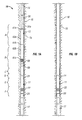
- FIG. 1A shows a preferred liner hanger tool 10 of the subject invention.
- Tool 10 includes a preferred embodiment 11 of the novel liner hangers which is connected to a running tool 12 (not shown) and a setting tool 13 .
- Tool 10 is connected at its upper end to a work string 14 assembled from multiple lengths of tubular sections threaded together through connectors.
- Work string 14 may be raised, lowered, and rotated as needed to transport tool 10 through an existing casing 15 cemented in a borehole through earth 16 .
- Work string 14 also is used to pump fluid into tool 10 and to manipulate it as required for setting hanger 11 .
- Hanger 11 includes a hanger mandrel 20, a swage 21, and a metal sleeve 22.
- a liner 17 is attached to the lower end of tool 10, more specifically to hanger mandrel 20 of hanger 11 .
- Liner 17 in turn is assembled from multiple lengths of tubular sections threaded together through connectors.
- liner 17 typically will have various other components as may be need to perform various operations in the well, both before and after setting hanger 11 .
- liner 17 typically will be cemented in place.
- tool 10 also will include, or the liner 17 will incorporate various well components used to perform such cementing operations, such as a slick joint, cement packoffs, plug landing collars, and the like (not shown).
- tool 10 Operation of tool 10 , as discussed in detail below, is accomplished in part by increasing hydraulic pressure within tool 10 .
- tool 10 or liner 17 preferably incorporate some mechanism to allow pressure to be built up in work string 14 , such as a seat (not shown) onto which a ball may be dropped.
- liner 17 also may include a drill bit (not shown) so that the borehole may be drilled and extended as liner 17 and tool 10 are lowered through existing casing 15 .
- the anchor and tool assemblies of the subject invention do not comprise any specific liner assemblies or a liner.
- the anchor assemblies may be used to install a variety of liner assemblies, and in general, may be used to install any other downhole tool or component that requires anchoring within a conduit, such as whipstocks, packers, bridge plugs, cement plugs, frac plugs, slotted pipe, and polished bore receptacles (PBRs).
- PBRs polished bore receptacles
- preferred liner hanger tool 10 is exemplified by showing a liner suspended in tension from the anchor assembly
- the novel anchor assemblies may also be used to support liners or other well components extending above the anchor assembly, or to secure such components in resistance to torsional forces.
- a "casing” is generally considered to be a tubular conduit lining a well bore and extending from the surface of the well.
- a “liner” is generally considered to be a tubular conduit that does not extend from the surface of the well, and instead is supported within an existing casing or another liner.
- casing shall refer to any existing conduit in the well into which the anchor assembly will be installed, whether it extends to the surface or not, and “liner” shall refer to a conduit having an external diameter less than the internal diameter of the casing into which the anchor assembly is installed.
- the tool has been exemplified in the context of casings and liners used in drilling oil and gas wells.
- the invention is not so limited in its application.
- the novel tool and anchor assemblies may be used advantageously in other conduits where it is necessary to install an anchor by working a tool through an existing conduit to install other tools or smaller conduits.
- liner hanger tool 10 is shown in its "run-in” position. That is, it has been lowered into existing casing 15 to the depth at which hanger 11 will be installed. Hanger 11 has not yet been “set” in casing 15 , that is, it has not been installed.
- FIG. 1B shows hanger 11 after it has been installed, that is, after it has been set in casing 15 and running tool 12 and setting tool 13 have been retrieved from the well. It will be noted in comparing the two figures that hanger mandrel 20 has remained in substantially the same position relative to casing 15, that swage 21 has travelled down tool 10 approximately the length of sleeve 22, and that sleeve 22 has been expanded radially outward into contact with casing 15.
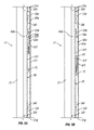
- FIGS. 7 show liner hanger 11 and various components of running tool 12.
- FIG. 7A shows hanger 11 in its "run-in” position
- FIG. 7B shows hanger 11 after it has been “set”
- FIG. 7C shows hanger tool 11 after it has been "released” from running tool 12.
- hanger mandrel 20 is a generally cylindrical body providing a conduit. It provides a connection at its lower end to, e.g ., a liner string (such as liner 17 shown in FIGS. 1 ) through threaded connectors or other conventional connectors.
- liner string such as liner 17 shown in FIGS. 1
- Other liners such as a patch liner, and other types of well components or tools, such as a whipstock, however, may be connected to mandrel 20, either directly or indirectly.
- liner hanger 11 it also may be viewed as the uppermost component of the liner or other well component that is being installed.
- mandrel 20 also is releasably engaged to running tool 12 .
- Swage 21 is supported for axial movement across the outer surface of mandrel 20. In the run-in position, it is proximate to expandable metal sleeve 22, i.e., it is generally axially removed from sleeve 22 and has not moved into a position to expand sleeve 22 into contact with an existing casing. In theory it may be spaced some distance therefrom, but preferably, as shown in FIG. 7A , swage 21 abuts metal sleeve 22. Sleeve 22 also is carried on the outer surface of mandrel 20.
- sleeve 22 is restricted from moving upward on mandrel 20 by swage 21 as shown and restricted from moving downward by its engagement with annular shoulder 23 on mandrel 20. It may be restricted, however, by other stops, pins, keys, set screws and the like as are known in the art.
- hanger 11 is set by actuating swage 21 , as will be described in greater detail below, to move across the outer surface of mandrel 20 from its run-in position, where it is proximate to sleeve 22 , to its set position, where it is under sleeve 22 .
- This downward movement of swage 21 causes metal sleeve 22 to expand radially into contact with an existing casing (such as casing 15 shown in FIGS 1 ).
- Movement of swage 21 under sleeve 22 preferably is facilitated by tapering the lower end of swage 21 and the upper end of sleeve 22, as seen in FIG. 7A .
- the facing surfaces of mandrel 20, swage 21, and sleeve 22 also are polished smooth and/or are provided with various structures to facilitate movement of swage 21 and to provide seals therebetween.
- outer surface of mandrel 20 and inner surface of sleeve 22 are provided with annular bosses in the areas denoted by reference numeral 24.
- bosses not only reduce friction between the facing surfaces as swage 21 is being moved, but when swage 21 has moved into place under sleeve 22, though substantially compressed and/or deformed, they also provide metal-to-metal seals between mandrel 20, swage 21, and sleeve 22. It will be understood, however, that annular bosses may instead be provided on the inner and outer surfaces of swage 21, or on one surface of swage 21 in lieu of bosses on either mandrel 20 or sleeve 22 . Coatings also may be applied to the facing surfaces to reduce the amount of friction resisting movement of swage 21 or to enhance the formation of seals between facing surfaces.
- the outer surface of swage 21, or more precisely, that portion of the outer surface of swage 21 that will move under sleeve 22 preferably is polished smooth to reduce friction therebetween.
- the inner surface of swage 21 preferably is smooth and polished to reduce friction with mandrel 20.
- the upper portion of swage 21 is able to provide a polished bore receptacle into which other well components may be installed.
- the novel anchor assemblies also include a ratchet mechanism that engages the mandrel and swage and resists reverse movement of the swage, that is, movement of the swage back toward its first position, in which it is axially proximate to the sleeve, and away from its second position, where it is under the sleeve.
- Liner hanger 11 for example, is provided with a ratchet ring 26 mounted between mandrel 20 and swage 21.
- Ratchet ring 26 has pawls that normally engage corresponding detents in annular recesses on, respectively, the outer surface of mandrel 20 and the inner surface of swage 21.
- Ratchet ring 26 is a split ring, allowing it to compress circumferentially, depressing the pawls and allowing them to pass under the detents on swage 21 as swage 21 travels downward in expanding sleeve 22.
- the pawls on ring 26 are forced into engagement with the detents, however, if there is any upward travel of swage 21.
- the effective outer diameter of the mandrel and the effective inner diameter of the swage are substantially equal, whereas the effective outer diameter of the swage is greater than the effective inner diameter of sleeve.
- swage 21 acts to radially expand sleeve 22 and, once sleeve 22 is expanded, mandrel 20 and swage 21 concentrically abut and provide radial support for sleeve 22, thereby enhancing the load capacity of hanger 11.
- hanger 11 may achieve equivalent load capacities with a shorter sleeve 22 , thus reducing the amount of force required to set hanger 11 .
- effective diameter it will be understood that reference is made to the profile of the part as viewed axially along the path of travel by swage 21 .
- the effective diameter takes into account any protruding structures such as annular bosses which may project from the nominal surface of a part.
- the outer diameter of mandrel 20 will be slightly greater than the inner diameter of swage 21 so that a seal may be created therebetween.
- substantially equal is intended to encompass such variations, and other normal tolerances in tools of this kind.
- hanger mandrel 20 is in a sense the uppermost component of liner 17 to be installed, it will be appreciated that its inner diameter preferably is at least as great as the inner diameter of liner 17 which will be installed. Thus, any further constriction of the conduit being installed in the well will be avoided. More preferably, however, it is substantially equal to the inner diameter of liner 17 so that mandrel 20 may be made as thick as possible.
- the mandrel of the novel anchor assemblies is substantially nondeformable, i.e ., it resists significant deformation when the swage is moved over its outer surface to expand the metal sleeve.
- expansion of the sleeve is facilitated and the mandrel is able to provide significant radial support for the expanded sleeve.
- some compression may be tolerable, on the order of a percent or so, but generally compression is kept to a minimum to maximize the amount of radial support provided.
- the mandrel of the novel anchors preferably is fabricated from relatively hard ferrous and non-ferrous metal alloys and, most preferably, from such metal alloys that are corrosion resistant.
- Suitable ferrous alloys include nickel-chromium-molybdenum steel and other high yield steel.
- Non-ferrous alloys include nickel, iron, or cobalt superalloys, such as Inconel, Hastelloy, Waspaloy, Rene, and Monel alloys.
- the superalloys are corrosion resistant, that is, they are more resistant to the chemical, thermal, pressure, and other corrosive conditions commonly encountered in oil and gas wells. Thus, superalloys or other corrosion resistant alloys may be preferable when corrosion of the anchor is a potential problem.
- the swage of the novel anchors also is preferably fabricated from such materials.
- high yield alloys not only is expansion of the sleeve facilitated, but the mandrel and swage also are able to provide significant radial support for the expanded sleeve and the swage may be made more resistant to corrosion as well.
- the sleeve of the novel anchor assemblies preferably is fabricated from ductile metal, such as ductile ferrous and non-ferrous metal alloys.
- the alloys should be sufficiently ductile to allow expansion of the sleeve without creating cracks therein. Examples of such alloys include ductile aluminum, brass, bronze, stainless steel, and carbon steel.
- the metal has an elongation factor of approximately 3 to 4 times the anticipated expansion of the sleeve. For example, if the sleeve is required to expand on the order of 3%, it will be fabricated from a metal having an elongation factor of from about 9 to about 12%.
- the material used to fabricate the sleeve should have an elongation factor of at least 10%, preferably from about 10 to about 20%.
- the sleeve should not be fabricated from material that is so ductile that it cannot retain its grip on an existing casing.
- the choice of materials for the mandrel, swage, and sleeve should be coordinated to provide minimal deformation of the mandrel, while allowing the swage to expand the sleeve without creating cracks therein.
- higher yield materials are used in the mandrel and swage, it is possible to use progressively less ductile materials in the sleeve. Less ductile materials may provide the sleeve with greater gripping ability, but of course will require greater expansion forces.
- the novel hangers do not have a weakened area such as exists at the junction of expanded and unexpanded portions of expandable liners. Thus, other factors being equal, the novel hangers are able to achieve higher load ratings.
- expandable liners must be made relatively thick in part to compensate for the weakened area created between the expanded and unexpanded portions.
- the expandable sleeves of the novel hangers are much thinner. Thus, other factors being equal, the expandable sleeves may be expanded more easily, which in turn reduces the amount of force that must be generated by the setting assembly.
- Ductile alloys from which both conventional expandable liners and the expandable sleeves of the novel hangers may be made, once expanded, can relax and cause a reduction in the radial force applied to an existing casing.
- Conventional tools have provided support for expanded liner portions by leaving the swage or other expanding member in the well.
- the nondeformable mandrel of the novel liner hangers has substantially the same outer diameter as the internal diameter of the swage. Thus, both the mandrel and the swage are able to provide radial support for the expanded sleeve.
- Expandable liner hangers since they necessarily are fabricated from ductile alloys which in general are less resistant to corrosion, are more susceptible to corrosion and may not be used, or must be used with the expectation of a shorter service life in corrosive environments.
- the mandrel of the novel hangers may be made of high yield alloys that are much more resistant to corrosion.
- the expandable sleeve of the novel hangers are fabricated from ductile, less corrosion resistant alloys, but it will be appreciated that as compared to a liner, only a relatively small surface area of the sleeve will be exposed to corrosive fluids.
- the length of the seal formed by the sleeve also is much greater than the thickness of a liner, expanded or otherwise. Thus, the novel hangers may be expected to have longer service lives in corrosive environments.
- the expandable sleeve of the novel anchor assemblies also preferably is provided with various sealing and gripping elements to enhance the seal between the expanded sleeve and an existing casing and to increase the load capacity of the novel hangers.
- sleeve 22 is provided with annular seals 27 and radially and axially spaced slips 28 provided on the outer surface thereof.
- Annular seals may be fabricated from a variety of conventional materials, such as wound or unwound, thermally cured elastomers and graphite impregnated fabrics.
- Slips may be provided by conventional processes, such as by machining slips into the sleeve, or by soldering crushed tungsten-carbide steel or other metal particles to the sleeve surface with a thin coat of high nickel based solder or other conventional solders.
- the sleeve also preferably is provided with gage protection to minimize contact between such elements and the casing wall as the anchor assembly is run into the well.
- the precise dimensions of the expandable sleeve may be varied so as to, other factors being equal, to provide greater or lesser load capacity and to allow for greater or lesser expansion forces.
- the external diameter of the sleeve necessarily will be determined primarily by the inner diameter of the liner into which the anchor will be installed and the desired degree of expansion.
- the thickness of the sleeve will be coordinated with the tensile and ductile properties of the material used in the sleeve so as to provide the desired balance of load capacity and expandability. In general, the longer the sleeve, the greater the load capacity.
- the sleeve typically will have a length at least equal to its diameter, and preferably a length of at least 150% of the diameter, so as to provide sufficient surface area to provide load capacities capable of supporting relatively heavy liners and other downhool tools and well components.
- the novel anchor assemblies thus may be provided with load capacities of at least 100,000 lbs, more preferably, at least 250,000 lbs, and most preferably, at least 500,000 lbs.
- the novel anchor assemblies are intended to be used in combination with a tool for installing the anchor in a tubular conduit.
- running tool 12 is used to releasably engage hanger 11 and setting tool 13 is used to actuate swage 21 and set sleeve 22 .
- setting tool 13 is used to actuate swage 21 and set sleeve 22 .
- the subject invention does not encompass any specific tool or mechanism for releasably engaging, actuating, or otherwise installing the novel anchor assemblies.
- the novel anchors are used with the tools disclosed herein. Those tools are capable of installing the novel anchors easily and reliably.
- they incorporate various novel features and represent other embodiments of the subject invention.
- Running tool 12 and setting tool 13 share a common tool mandrel 30 .
- Tool mandrel 30 provides a base structure to which the various components of liner hanger 11, running tool 12, and setting tool 13 are connected, directly or indirectly.
- Tool mandrel 30 is connected at its upper end to a work string 14 (see FIG. 1A ). Thus, it provides a conduit for the passage of fluids from the work string 14 that are used to balance hydrostatic pressure in the well and to hydraulically actuate setting tool 13 and, ultimately, swage 21. Mandrel 30 also provides for transmission of axial and rotational forces from work string 14 as are necessary to run in the hanger 11 and liner 17, drill a borehole during run-in, set the hanger 11 , and release and retrieve the running tool 12 and setting tool 13, all as described in further detail below.
- Tool mandrel 30 is a generally cylindrical body. Preferably, as illustrated, it comprises a plurality of tubular sections 31 to facilitate assembly of tool 10 as a whole. Tubular sections 31 may be joined by conventional threaded connectors. Preferably, however, the sections 31 of tool mandrel 30 are connected by novel clutch mechanisms of the subject invention.
- the novel clutch mechanisms comprise shaft sections having threads on the ends to be joined.
- the shaft sections have prismatic outer surfaces adjacent to their threaded ends.
- a threaded connector joins the threaded ends of the shaft sections.
- the connector has axial splines.
- a pair of clutch collars is slidably supported on the prismatic outer surfaces of the shaft sections.
- the clutch collars have prismatic inner surfaces that engage the prismatic outer surfaces of the shaft sections and axial splines that engage the axial splines on the threaded connector.
- the novel clutch mechanisms also comprise recesses adjacent to the mating prismatic surfaces that allow limited rotation of the clutch collars on the prismatic shaft sections to facilitate engagement and disengagement of the mating prismatic surfaces.
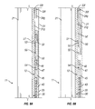
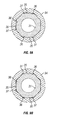
- mandrel 30 of tool 10 includes a preferred embodiment 32 of the novel clutch mechanisms. More particularly, mandrel 30 is made up of a number of tubular sections 31 joined by novel connector assemblies 32. Connector assemblies 32 include threaded connectors 33 and clutch collars 34. FIGS. 8-9 show the portion of mandrel 30 and connector assembly 32a which is seen in FIGS. 2 and which is representative of the connections used to make up mandrel 30. As may be seen in those figures, lower end of tubular section 31a and upper end of tubular section 31b are threaded into and joined by threaded connector 33a .
- Clutch collars 34a and 34b are slidably supported on tubular sections 31a and 31b, and when in their coupled or "made-up" position as shown in FIG. 8A , abut connector 33a. Connector 33a and collars 34a and 34b have mating splines which provide rotational engagement therebetween.
- Tubular sections 31 have prismatic outer surfaces 35 adjacent to their threaded ends. That is, the normally cylindrical outer surfaces of tubular sections 31 have been cut to provide a plurality of flat surfaces extending axially along the tubular section such that, when viewed in cross section, flat surfaces define or can be extended to define a polygon.
- tubular section 31a has octagonal prismatic outer surfaces 35.
- the inner surface of clutch collar 34a has mating octagonal prismatic inner surfaces 36.
- Clutch collar 34b is of similar construction.
- prismatic surfaces 35 and 36 provide rotational engagement between sections 31a and 31b and collars 34a and 34b. It will be appreciated, therefore, that torque may be transmitted from one tubular section 31 to another tubular section 31, via collars 34 and connectors 33, without applying torque to the threaded connections between the tubular sections 31.
- FIGS. 8B and 9B show connector assembly 32a in uncoupled states.
- prismatic surfaces 35 extend axially on tubular sections 31a and 31b and allow the splines on collars 34a and 34b to slide into and out of engagement with the splines on connector 33a, as may be appreciated by comparing FIGS. 8A and 8B .
- Recesses preferably are provided adjacent to the mating prismatic surfaces to facilitate that sliding.
- recesses 37 are provided adjacent to prismatic surfaces 36 on collar 34a . Those recesses allow collar 34a to rotate to a limited degree on tubular sections 31a . When rotated to the left, as shown in FIG.
- the novel clutch mechanisms provide for reliable and effective transmission of torque in both directions through a sectioned conduit, such as tool mandrel 30 .
- a sectioned conduit such as tool mandrel 30 .
- mating prismatic surfaces and splines on the connector and collars provide much greater surface area through which right-handed torque is transmitted.
- much greater rotational forces, and forces well in excess of the torque limit of the threaded connection may be transmitted in a clockwise direction through a sectioned conduit and its connector assemblies without risking damage to threaded connections.
- the novel clutch mechanisms therefore, are particularly suited for tools used in drilling in a liner and other applications that subject the tool to high torque.
- the collars cannot rotate in a counterclockwise direction, or if recesses are provided can rotate in a counterclockwise direction only to a limited degree, left-handed torque may be applied to a tool mandrel without risk of significant loosening or of unthreading the connection.
- the tool may be designed to utilize reverse rotation, such as may be required for setting or release of a liner or other well component, without risking disassembly of the tool in a well bore.
- mandrel 30 may be made up with conventional connections.
- novel liner hangers may be used with tools having a conventional mandrel, and thus, the novel clutch mechanisms form no part of that aspect of the subject invention.
- novel clutch mechanisms may be used to advantage in making up any tubular strings, in mandrels for other tools, or in other sectioned conduits or shafts, or any other threaded connection where threads must be protected from excessive torque.
- Running tool 12 includes a collet mechanism that releasably engages hanger mandrel 20 and which primarily bears the weight of liner 17 or other well components connected directly or indirectly to hanger mandrel 20.
- Running tool 12 also includes a releasable torque transfer mechanism for transferring torque to hanger mandrel 20 and a releasable dog mechanism that provides a connection between running tool 12 and tool mandrel 30.
- Tubular section 31g of mandrel 30 provides a base structure on which the various other components of running tool 12 are assembled. As will be appreciated from the discussion follows, most of those other components are slidably supported, directly or indirectly, on tubular section 31g. During assembly of tool 10 and to a certain extent in their run-in position, however, they are fixed axially in place on tubular section 31g by the dog mechanism, which can be released to allow release of the collet mechanism engaging hanger mandrel 20.
- running tool 12 includes a collet 40 which has an annular base slidably supported on mandrel 30.
- a plurality of fingers extends axially downward from the base of collet 40.
- the collet fingers have enlarged ends 41 which extend radially outward and, when tool 10 is in its run-in position as shown in FIG. 7A , engage corresponding annular recesses 29 in hanger mandrel 20.
- a bottom collar 42 is threaded onto the end of tool mandrel 30, and its upper beveled end provides radial and axial support for the ends 41 of collet 40.
- collet 40 is able to bear the weight of mandrel 20, liner 17, and any other well components that may be connected directly or indirectly thereto.
- bottom collar 42 also may provide a connection, e.g ., via a threaded lower end, to a slick joint or other well components.
- collet 40 or more precisely, its annular base is slidably supported on mandrel 30 within an assembly including a sleeve 43, an annular collet cap 46 , an annular sleeve cap 44, and annular thrust cap 45.
- Sleeve 43 is generally disposed within hanger mandrel 20 and slidably engages the inner surface thereof.
- Sleeve cap 44 is threaded to the lower end of sleeve 43 and is slidably carried between hanger mandrel 20 and collet 40 .
- Thrust cap 45 is threaded to the upper end of sleeve 43 and is slidably carried between swage 21 and tubular section 31g .
- Collet cap 46 is threaded to the upper end of collet 40 and is slidably carried between sleeve 43 and tubular section 31g.
- the collet 40 and cap 46 subassembly is spring loaded within sleeve 43 between sleeve cap 44 and thrust cap 45.
- thrust cap 45 abuts at its upper end an annular dog housing 47 and abuts hanger mandrel 20 at its lower end.
- Hanger mandrel 20 and thrust cap 45 rotationally engage each other via mating splines, similar to those described above in reference to the connector assemblies 32 joining tubular sections 31 .
- tubular section 31g is provided with lugs, radially spaced on its outer surface, which rotationally engage corresponding slots in thrust cap 45 .
- the slots extend laterally and circumferentially away from the lugs to allow, for reasons discussed below, tubular section 31g to move axially downward and to rotate counterclockwise a quarter-turn.
- Running tool 12 may be used to drill in a liner. That is, a drill bit may be attached to the end liner 17 and the well bore extended by rotating work string 14.
- dog housing 47 and tubular section 31g of mandrel 30 have cooperating recesses that entrap a plurality of dogs 48 as is common in the art. Those recesses allow dogs 48 to move radially, that is, in and out to a limited degree. It will be appreciated that the inner ends (in this sense, the bottom) of dogs 48 are provided with pawls which engage the recess in tubular section 31g. The annular surfaces of those pawls and recesses are coordinated such that downward movement of mandrel 30 relative to dog housing 47, for reasons to be discussed below, urges dogs 48 outward. In the run-in position, as shown in FIG.
- a locking piston 50 which is slidably supported on tubular section 31g, overlies dog housing 47 and the tops of the cavities in which dogs 48 are carried.
- dogs 48 are held in an inward position in which they engage both dog housing 47 and tubular section 31g .
- dogs 48 are able to provide a translational engagement between mandrel 30 and running tool 12 when tool 10 is in the run-in position. This engagement is not typically loaded with large amounts of force when the tool is in its run-in position, as the weight of tool 10 and liner 17 is transmitted to tool mandrel 30 primarily through collet ends 41 and bottom collar 41 and torque is transmitted from mandrel 30 through thrust cap 45 and hanger mandrel 20 .
- the engagement provided by dogs 48 facilitates assembly of tool 10 and will bear any compressive load inadvertently applied between hanger 11 and tool mandrel 30 .
- dogs 48 will prevent liner hanger 11 and running tool 12 from moving upward on mandrel 30 such as might otherwise occur if tool 10 gets hung up as it is run into an existing casing. Release of dogs 48 from that engagement will be described in further detail below in the context of setting hanger 11 and release of running tool 12 .
- running tool 12 described above provides a reliable, effective mechanism for releasably engaging liner hanger 11 , for securing liner hanger from moving axially on mandrel 30, and for transmitting torque from mandrel 30 to hanger mandrel 20 .
- it is a preferred tool for use with the liner hangers of the subject invention.
- other conventional running mechanisms such as mechanisms utilizing a left-handed threaded nut or dogs only, may be used, particularly if it is not necessary or desirable to provide for the transmission of torque through the running mechanism.
- the subject invention is in no way limited to a specific running tool.
- Setting tool 13 includes a hydraulic mechanism for generating translational force, relative to the tool mandrel and the work string to which it is connected, and a mechanism for transmitting that force to swage 21 which, upon actuation, expands metal sleeve 22 and sets hanger 11 . It is connected to running tool 12 through their common tool mandrel 30 , with tubular sections 31a-f of mandrel 30 providing a base structure on which the various other components of setting tool 13 are assembled.
- the hydraulic mechanism comprises a number of cooperating hydraulic actuators 60 supported on tool mandrel 30 .
- Those hydraulic actuators are linear hydraulic motors designed to provide linear force to swage 21 .
- actuators 60 are interconnected so as to "stack" the power of each actuator 60 and that their number and size may be varied to create the desired linear force for expanding sleeve 22 .
- the mandrel in the novel actuators preferably is a generally cylindrical mandrel.
- a stationary sealing member such as a piston, seal, or an extension of the mandrel itself, extends continuously around the exterior of the mandrel.
- a hydraulic barrel or cylinder is slidably supported on the outer surfaces of the mandrel and the stationary sealing member.
- the cylinder includes a sleeve or other body member with a pair of dynamic sealing members, such as pistons, seals, or extensions of the body member itself, spaced on either side of the stationary sealing member and slidably supporting the cylinder.
- the stationary sealing member divides the interior of the cylinder into two hydraulic chambers, a top chamber and a bottom chamber.
- An inlet port provides fluid communication into the bottom hydraulic chamber.
- An outlet port provides fluid communication into the top hydraulic chamber.
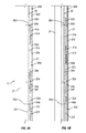
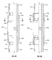
- FIGS. 4 what may be viewed as the lowermost hydraulic actuator 60e is shown in FIGS. 4 .
- This lowermost hydraulic actuator 60e comprises floating annular pistons 61e and 61f.
- Floating pistons 61e and 61f are slidably supported on tool mandrel 30, or more precisely, on tubular sections 31e and 31f, respectively.
- a cylindrical sleeve 62e is connected, for example, by threaded connections to floating pistons 61e and 61f and extends therebetween.
- An annular stationary piston 63e is connected to tubular section 31f of tool mandrel 30, for example, by a threaded connection.
- set screws, pins, keys, or the like are provided to secure those threaded connections and to reduce the likelihood they will loosen.
- floating piston 61f In the run-in position shown in FIG. 4A , floating piston 61f is in close proximity to stationary piston 63e. A bottom hydraulic chamber is defined therebetween, either by spacing the pistons or by providing recesses in one or both of them, and a port is provided through the mandrel to allow fluid communication with the bottom hydraulic chamber.
- floating piston 61f and stationary piston 63e are provided with recesses which define a bottom hydraulic chamber 64e therebetween, even if pistons 61f and 63e abut each other.
- One or more inlet ports 65e are provided in tubular section 31f to provide fluid communication between the interior of tool mandrel 30 and bottom hydraulic chamber 64e .
- Floating piston 61e is distant from stationary piston 63e , and a top hydraulic chamber 66e is defined therebetween.
- One or more outlet ports 67e are provided in floating piston 61e to provide fluid communication between top hydraulic chamber 66e and the exterior of cylinder sleeve 62e.
- outlet ports could be provided in cylinder sleeve 62e, and it will be appreciated that the exterior of cylinder sleeve 62e is in fluid communication with the exterior of the tool, i.e., the well bore, via clearances between cylinder sleeve 62e and swage 21 .
- inlet ports 65e into bottom hydraulic chamber 64e will urge floating piston 61f downward, and in turn cause fluid to flow out of top hydraulic chamber 66e through outlet ports 67e and allow actuator 60e to travel downward along mandrel 30 , as may be seen in FIG. 4B .
- Setting tool 13 includes another actuator 60d of similar construction located above actuator 60e just described. Parts of actuator 60d are shown in FIGS. 3 and 4 .
- engagement actuator 60c comprises a pair of floating pistons 61c and 61d connected by a sleeve 62c.
- Floating pistons 61c and 61d are slidably supported, respectively, on tubular sections 31c and 31d around stationary piston 63c.
- One or more inlet ports 65c are provided in tubular section 31c to provide fluid communication between the interior of tool mandrel 30 and bottom hydraulic chamber 64c.
- One or more outlet ports 67c are provided in cylinder sleeve 62c to provide fluid communication between top hydraulic chamber 66c and the exterior of actuator 60c.
- sleeve 62c extends above swage 21 while its lower portion extends through swage 21, and that upper end of sleeve 62c is enlarged relative to its lower portion.
- An annular adjusting collar 68 is connected to the reduced diameter portion of sleeve 62c via, e.g ., threaded connections.
- An annular stop collar 69 is slidably carried on the reduced diameter portion of sleeve 62c spaced somewhat below adjusting collar 68 and just above and abutting swage 21 . Adjusting collar 68 and stop collar 69 are tied together by shear pins (not shown) or other shearable members.
- Setting tool 13 includes what may be viewed as additional drive actuators 60a and 60b located above engagement actuator 60c shown in FIGS. 3 .
- the uppermost hydraulic actuator 60a comprises a pair of floating pistons 61a and 61b connected by a sleeve 62a and slidably supported, respectively, on tubular sections 31a and 31b around stationary piston 63a.
- One or more inlet ports 65a are provided in tubular section 31a to provide fluid communication between the interior of tool mandrel 30 and bottom hydraulic chamber 64a.
- One or more outlet ports 67a are provided in floating piston 61a to provide fluid communication between top hydraulic chamber 66a and the exterior of actuator 60a. (It will be understood that actuator 60b, as shown in part in FIGS. 2 and 3 , is constructed in a fashion similar to actuator 60a .)
- hydraulic actuators 60 preferably are immobilized in their run-in position. Otherwise, they may be actuated to a greater or lesser degree by differences in hydrostatic pressure between the interior of mandrel 30 and the exterior of tool 10 .
- setting tool 13 preferably incorporates shearable members, such as pins, screws, and the like, or other means of releasably fixing actuators 60 to mandrel 30 .
- the setting tool 13 preferably incorporates the hydraulic actuators of the subject invention.
- the novel hydraulic actuators include a balance piston.
- the balance piston is slidably supported within the top hydraulic chamber of the actuator, preferably on the mandrel.
- the balance piston includes a passageway extending axially through the balance piston. Fluid communication through the piston and between its upper and lower sides is controlled by a normally shut valve in the passageway.
- the balance piston is able to slide in response to a difference in hydrostatic pressure between the outlet port, which is on one side of the balance piston, and the portion of the top hydraulic chamber that is on the bottom side of the balance piston.
- actuator 60a includes balance piston 70a.
- Balance piston 70a is slidably supported on tubular section 31a of mandrel 30 in top hydraulic chamber 66a between floating piston 61a and stationary piston 63a.
- balance piston 70a is located in close proximity to floating piston 61a.
- a hydraulic chamber is defined therebetween, either by spacing the pistons or by providing recesses in one or both of them, and a port is provided through the mandrel to allow fluid communication with the hydraulic chamber.
- floating piston 61a is provided with a recess which defines a hydraulic chamber 71a therebetween, even if pistons 61a and 70a abut each other.
- Balance piston 70a has a passageway 72a extending axially through its body portion, i.e ., from its upper side to its lower side. Passageway 72a is thus capable of providing fluid communication through balance piston 70a, that is, between hydraulic chamber 71a and the rest of top hydraulic chamber 66a. Fluid communication through passageway 72a, however, is controlled by a normally shut valve, such as rupturable diaphragm 73a. When diaphragm 73a is in its closed, or unruptured state, fluid is unable to flow between hydraulic chamber 71a and the rest of top hydraulic chamber 66a.
- a normally shut valve such as rupturable diaphragm 73a.
- Actuator 60b also includes a balance piston 70b identical to balance piston 70a described above.
- balance pistons 70a and 70b are able to equalize pressure between the top hydraulic chambers 66a and 66b and the exterior of actuators 60a and 60b such as might develop, for example, when tool 10 is being run into a well. Fluid is able to enter outlet ports 67a and 67b and, to the extent that such exterior hydrostatic pressure exceeds the hydrostatic pressure in top hydraulic chambers 66a and 66b , balance pistons 70a and 70b will be urged downward until the pressures are balanced.
- Such balancing of internal and external pressures is important because it avoids deformation of cylinder sleeves 62a and 62b that could interfere with travel of sleeves 62a and 62b over stationary pistons 63a and 63b .
- balance pistons 70a and 70b further enhance the reliability of actuators 60a and 60b . That is, balance pistons 70a and 70b greatly reduce the amount of debris that can enter top hydraulic chambers 66a and 66b, and since they are located in close proximity to outlet ports 67a and 67b, the substantial majority of the travel path is maintained free and clear of debris.
- Hydraulic chambers 66a and 66b preferably are filled with clean hydraulic fluid during assembly of tool 10, thus further assuring that when actuated, floating pistons 61a and 61b and sleeves 62a and 62b will slide cleanly and smoothly over, respectively, tubular sections 31a and 31b and stationary pistons 63a and 63b .
- the exact location of the balance piston in the top hydraulic chamber of the novel actuators is not critical. It may be spaced relatively close to a stationary piston and still provide such balancing. In practice, the balance piston will not have to travel a great distance to balance pressures and, therefore, it may be situated initially at almost any location in the top hydraulic chamber between the external opening of the outlet port and the stationary piston.
- the balance piston in the novel actuators is mounted as close to the external opening of the outlet port as practical so as to minimize exposure of the inside of the actuator to debris from a well bore. It may be mounted within a passageway in what might be termed the "port,” such as ports 67a shown in the illustrated embodiment 60a, or within what might otherwise be termed the "chamber,' such as top hydraulic chamber 66a shown in the illustrated embodiment 60a.
- the top hydraulic chamber may be understood as including all fluid cavities, chambers, passageways and the like between the port exit and the stationary piston.
- the balance piston 70a is mounted on tubular sections 31a in the relatively larger top hydraulic chamber 66a .
- the normally shut valves in the balance position should be selected such that they preferably are not opened to any significant degree by the pressure differentials they are expected to encounter prior to actuation of the actuator. At the same time, as will be appreciated from the discussion that follows, they must open, that is, provide release of increasing hydrostatic pressure in the top hydraulic chamber when the actuator is actuated. Most preferably, the normally shut valves remain open once initially opened. Thus, rupturable diaphragms are preferably employed because they provide reliable, predictable release of pressure, yet are simple in construction and can be installed easily. Other normally shut valve devices, such as check valves, pressure relief valves, and plugs with shearable threads, however, may be used in the balance piston on the novel actuators.
- the actuator includes stationary and dynamic seals as are common in the art to seal the clearances between the components of the actuator and to provide efficient operation of the actuator as described herein.
- the clearances separating the balance piston from the mandrel and from the sleeve, that is, the top hydraulic chamber preferably are provided with dynamic seals to prevent unintended leakage of fluid around the balance piston.
- the seals may be mounted on the balance piston or on the chamber as desired.
- balance pistons 70a and 70b may be provided with annular dynamic seals (not shown), such as elastomeric O-rings mounted in grooves, on their inner surface abutting tubular sections 31a and 31b and on their outer surfaces abutting sleeves 62a and 62b , respectively.
- annular dynamic seals such as elastomeric O-rings mounted in grooves, on their inner surface abutting tubular sections 31a and 31b and on their outer surfaces abutting sleeves 62a and 62b , respectively.
- one or both of the seals may be mounted on the top hydraulic chambers 66a and 66b, for example, in grooves on tubular sections 31a and 31b or sleeves 62a and 62b.
- the balance pistons Prior to actuation, the balance pistons essentially seal the top hydraulic chambers and prevent the incursion of debris. Under certain conditions, however, such as increasing downhole temperatures, pressure within the top hydraulic chambers can increase beyond the hydrostatic pressure in the well bore. The balance pistons will be urged upward until pressure in the top hydraulic chambers is equal to the hydraulic pressure in the well bore. In the event that a balance piston "bottoms" out against the outlet port, however, pressure within the top hydraulic chamber could continue to build, possibly to the point where a diaphragm would be ruptured, thereby allowing debris laden fluid from the well bore to enter the chamber.
- the novel actuators preferably incorporate a pressure release device allowing release of potentially problematic pressure from the top hydraulic chamber as might otherwise occur if the balance pistons bottom out.
- check valves or pressure relief valves may be mounted in passageways 72a and 72b.
- Such valves if used, should also allow a desired level of fluid flow through passageways 72a and 72b during actuation.
- an elastomeric burp seal (not shown) may be mounted in one or both of the clearances separating the balance pistons 70a and 70b from, respectively, tubular sections 31a and 31b and sleeves 62a and 62b.
- burp seals would then allow controlled release of fluid from top hydraulic chambers 66a and 66b to, respectively, hydraulic chambers 71a and 71b if balance pistons 70a and 70b were to bottom out against, respectively, floating pistons 61a and 61b .
- Such burp valves would, of course, be designed with a release pressure sufficiently below the pressure required to open the rupturable diaphragm or other normally shut valve.
- the pressure relief device is provided in the cylindrical mandrel.
- a check or pressure release valve (not shown) may be mounted in tubular sections 31a and 31b so as to allow controlled release of fluid from top hydraulic chambers 66a and 66b to the interior of mandrel 30 .
- Such an arrangement has an advantage over a burp seal as described above in that it would be necessary to overcome flow through a burp seal in order to build up sufficient pressure to rupture a diaphragm or otherwise to open a normally shut valve device. If a pressure relief device is provided in the cylindrical mandrel, pressure in the top hydraulic chamber will be equal to pressure within the interior of the mandrel, and there will be no flow through the pressure release device that must be overcome.
- setting tool 13 includes a slidable, indicator ring 75 supported on tubular section 31f just below actuator 60e described above.
- indicator ring 75 is fixed to tubular section 31f via a shear member, such as a screw or pin (not shown). It is positioned on section 31f relative to floating piston 61f, however, such that when floating piston 61f has reached the full extent of its travel, it will impact indicator ring 75 and shear the member fixing it to section 31f.
- indicator ring 75 will be able to slide freely on mandrel 30 and, when the tool is retrieved from the well, it may be readily confirmed that setting tool 13 fully stroked and set metal sleeve 22.
- setting tool 13 described above provides a reliable, effective mechanism for actuating swage 21 , and it incorporates novel hydraulic actuators providing significant advantages over the prior art.
- it is a preferred tool for use with the anchor assemblies of the subject invention.
- hydraulic and other types of mechanisms which are commonly used in downhole tools to generate linear force and motion, such as hydraulic jack mechanisms and mechanisms actuated by explosive charges or by releasing weight on, pushing, pulling, or rotating the work string.
- such mechanism may be adapted for use with the novel anchor assemblies, and it is not necessary to use any particular setting tool or mechanism to set the novel anchor assemblies.
- the novel setting assemblies because they include hydraulic actuators having a balance piston, are able to balance hydraulic pressures that otherwise might damage the actuator and are able to keep the actuator clear of debris that could interfere with its operation.
- Such improvements are desirable not only in setting the anchor assemblies of the subject invention, but also in the operation of other downhole tools and components where hydraulic actuators or other means of generating linear force are required.
- the subject invention in this aspect is not limited to use of the novel setting assemblies to actuate a particular anchor assembly or any other downhole tool or component.
- running tool 12 and setting tool 13 thus far has focused primarily on the configuration of those tools in their run-in position.
- tool 10 tool When in its run-in position, tool 10 tool may be lowered into an existing casing, with our without rotation. If a liner is being installed, however, a drill bit preferably is attached to the end of the liner, as noted above, so that the liner may be drilled in.
- tool mandrel 30 provides a conduit for circulation of fluids as may be needed for drilling or other operations in the well.
- liner hanger 11 is set by increasing the fluid pressure within mandrel 30. Increased fluid pressure actuates setting tool 13, which urges swage 21 downward and under expandable sleeve 22. At the same time, increasing fluid pressure in mandrel 30 causes a partial release of running tool 12 from mandrel 30. Once tool 10 is in this set position, running tool 12 may be released from liner hanger 11 by releasing weight on mandrel 30 through work string 14. Alternately, in the event that release does not occur, running tool 12 may be released from liner hanger 11 by rotating mandrel 30 a quarter-turn counterclockwise prior to releasing weight.
- liner 17 may be cemented in place.
- the cementing operation will allow fluid pressure to be built up within work string 14 and mandrel 30. If a cementing operation will not first be performed, for whatever reason, it will be appreciated that other means will be provided, such as a ball seat, for allowing pressure to be built up.
- mandrel 30 not only causes setting of liner hanger 11, but also causes a partial release of running tool 12 from mandrel 30. More specifically, as understood best by comparing FIGS. 6A and 6B , increasing fluid pressure in mandrel 30 causes fluid to pass through one or more ports 51 in tubular section 31g into a small hydraulic chamber 52 defined between locking piston 50 and annular seals 53 provided between piston 50 and section 31g . As fluid flows into hydraulic chamber 52, locking piston 50 is urged upward along tubular section 31g and away from dog housing 47.
- That movement of locking piston 50 uncovers recesses in dog housing 47.
- dogs 48 are able to move radially (to a limited degree) within those recesses. Once uncovered, however, dogs 48 will be urged outward and out of engagement with tubular section 31g if mandrel 30 is moved downward.
- running tool 12 is partially released from mandrel 30 in the sense that mandrel 30, though restricted from relative upward movement, is now able to move downward relative to running tool 12.
- Other mechanisms for setting and releasing dogs such as those including one or a combination of mechanical or hydraulic mechanisms, are known, however, and may be used in running tool 12 .
- FIGS. 6C and 7C show the lower sections of tool 10 in their release positions.
- running tool 12 is released from hanger 11 by releasing weight onto mandrel 30 via work string 14 while fluid pressure within mandrel 30 is reduced.
- setting tool 13 which is held stationary by its engagement through stop collar 69 with the upper end of swage 21, is able to ride up mandrel 30.
- dogs 48 now are able to move radially out of engagement with tubular section 31g as discussed above, and as weight is released onto tool 10 mandrel 30 is able to move downward relative to running tool 12.
- An expanded C-ring 54 is carried on the outer surface of tubular section 31g in a groove in dog housing 47. As mandrel 30 travels downward, expanded C-ring 54 encounters and is able to relax somewhat and engage another annular groove in tubular section 31g, thus laterally re-engaging running tool 12 with tool mandrel 30. The downward travel of mandrel 30 preferably is limited to facilitate this re-engagement.
- an expanded C-ring and cover ring assembly 55 is mounted on tubular section 31g such that it will engage the upper end of dog housing 47 , stopping mandrel 30 and allowing expanded C-ring 54 to engage the mating groove in tubular section 31g.
- running tool 12 In the event running tool 12 is not released from mandrel 30 as tool 10 is set, it will be appreciated that it may be released by rotating mandrel 30 a quarter-turn counterclockwise and then releasing weight on mandrel 30. That is, left-handed "J" slots (not shown) are provided in tubular section 31g. Such "J" slots are well known in the art and provide an alternate method of releasing running tool 12 from hanger mandrel 20. More specifically, dogs 48 may enter lateral portions of the "J" slots by rotating mandrel 30 a quarter-turn counterclockwise. Upon reaching axial portions of the slots, weight may be released onto mandrel 30 to move it downward relative to running tool 12.
- shear wires or other shear members are provided to provide a certain amount of resistance to such counterclockwise rotation in order to minimize the risk of inadvertent release.
Abstract
Description
- The present invention relates to downhole tools used in oil and gas well drilling operations and, more particularly, to a hydraulic setting assembly which may be used to actuate anchors for well liners and other downhole tools and to tools and methods utilizing the novel hydraulic setting assembly.
- Hydrocarbons, such as oil and gas, may be recovered from various types of subsurface geological formations. The formations typically consist of a porous layer, such as limestone and sands, overlaid by a nonporous layer. Hydrocarbons cannot rise through the nonporous layer, and thus, the porous layer forms a reservoir in which hydrocarbons are able to collect. A well is drilled through the earth until the hydrocarbon bearing formation is reached. Hydrocarbons then are able to flow from the porous formation into the well.
- In what is perhaps the most basic form of rotary drilling methods, a drill bit is attached to a series of pipe sections referred to as a drill string. The drill string is suspended from a derrick and rotated by a motor in the derrick. As the drilling progresses downward, the drill string is extended by adding more pipe sections.
- A drilling fluid or "mud" is pumped down the drill string, through the bit, and into the well bore. This fluid serves to lubricate the bit and carry cuttings from the drilling process back to the surface. As a well bore is drilled deeper and passes through hydrocarbon producing formations, however, the production of hydrocarbons must be controlled until the well is completed and the necessary production equipment has been installed. The drilling fluid also is used to provide that control. That is, the hydrostatic pressure of drilling fluid in the well bore relative to the hydrostatic pressure of hydrocarbons in the formation is adjusted by varying the density of the drilling fluid, thereby controlling the flow of hydrocarbons from the formation.
- When the drill bit has reached the desired depth, larger diameter pipes, or casings, are placed in the well and cemented in place to prevent the sides of the borehole from caving in. The casing then is perforated at the level of the oil bearing formation so oil can enter the cased well. If necessary, various completion processes are performed to enhance the ultimate flow of oil from the formation. The drill string is withdrawn and replaced with a production string. Valves and other production equipment are installed in the well so that the hydrocarbons may flow in a controlled manner from the formation, into the cased well bore, and through the production string up to the surface for storage or transport.
- This simplified drilling process, however, is rarely possible in the real world. For various reasons, a modem oil well will have not only a casing extending from the surface, but also one or more pipes, i.e., casings, of smaller diameter running through all or a part of the casing. When those "casings" do not extend all the way to the surface, but instead are mounted in another casing, they are referred to as "liners." Regardless of the terminology, however, in essence the modern oil well typically includes a number of tubes wholly or partially within other tubes.
- Such "telescoping" tubulars, for example, may be necessary to protect groundwater from exposure to drilling mud. A liner can be used to effectively seal the aquifer from the borehole as drilling progresses. Also, as a well is drilled deeper, especially if it is passing through previously depleted reservoirs or formations of differing porosities and pressures, it becomes progressively harder to control production throughout the entire depth of the borehole. A drilling fluid that would balance the hydrostatic pressure in a formation at one depth might be too heavy or light for a formation at another depth. Thus, it may be necessary to drill the well in stages, lining one section before drilling and lining the next section. Portions of existing casing also may fail and may need to be patched by installing liners within damaged sections of the casing.
- The traditional approach to installing a liner in an existing casing has been to connect or "tie" the liner into an anchor, that is, a "liner hanger." Conventional anchors have included various forms of mechanical slip mechanisms that are connected to the liner. The slips themselves typically are in the form of cones or wedges having teeth or roughened surfaces. The typical hanger will include a relatively large number of slips, as many as six or more. A running and/or setting tool is used to position the anchor in place and drive the slips from their initial, unset position, into a set position where they are able to bite into and engage the existing casing. The setting mechanisms typically are either hydraulic, which are actuated by increasing the hydraulic pressure within the tool, or mechanical, which are actuated by rotating, lifting, or lowering the tool, or some combination thereof.
- Such mechanical slip hangers may be designed to adequately support the weight of long liners. In practice, however, the wedges, cones, and the like that are intended to grip the existing casing may partially extend as the tool is run through existing casing and can cause the hanger to get stuck. They also may break off and interfere with other tools already in the well or make it difficult to run other tools through the casing at a later time. Moreover, separate "packers" must be used with such anchors if a seal is required between the liner and the existing casing.
- One approach to avoiding such problems has been to eliminate in a sense the anchor entirely. That is, instead of tying a liner into an anchor, a portion of the liner itself is expanded into contact with an existing casing, making the liner essentially self-supporting and self-sealing. Thus, the liner conduit is made of sufficiently ductile metal to allow radial expansion of the liner, or more commonly, a portion of the liner into contact with existing casing. Various mechanisms, both hydraulic and mechanical, are used to expand the liner. Such approaches, however, all rely on direct engagement of, and sealing between the expanded liner and the existing casing.
- For example,
U.S. Pat. 6,763,893 to B. Braddick discloses a patch liner assembly that is used, for example, to repair existing casing. The patch assembly comprises a pair of expandable conduits, that is, an upper expandable liner and a lower expandable liner. The expandable liners are connected to the ends of a length of "patch" conduit. The patch assembly is set within the casing by actuating sets of expanding members that radially expand a portion of each expandable liner into engagement with the casing. Once expanded, the expanded portion of the liners provide upper and lower seals that isolate the patched portion of the existing casing. The expanded liners, together with the patch conduit, thereafter provide a passageway for fluids or for inserting other tubulars or tools through the well. -
U.S. Pat. 6,814,143 to B. Braddick andU.S. Pat. 7,278,492 to B. Braddick disclose patch liner assemblies which, similar to Braddick '893, utilize a pair of expandable liners connected via a length of patch conduit. The upper and lower liners are expanded radially outward via a tubular expander into sealing engagement with existing casing. Unlike the expanding members in Braddick '893, however, the tubular expanders disclosed in Braddick `143 and '492 are not withdrawn after the liner portions have been expanded. They remain in the expanded, set liner such that they provide radial support for the expanded portions of the liner. -
U.S. Pat. 7,225,880 to B. Braddick discloses an approach similar to Braddick '143 and '492, except that it is applied in the context of extension liners, that is, a smaller diameter liner extending downward from an existing, larger diameter casing. An expandable liner is expanded radially outward into sealing engagement with the existing casing via a tubular expander. The tubular expander is designed to remain in the liner and provide radial support for the expanded liner. -
U.S. Pat. 7,387,169 to S. Harrell et al. also discloses various methods of hanging liners and tying in production tubes by expanding a portion of the tubular via, e.g., a rotating expander tool. All such methods rely on creating direct contact and seals between the expanded portion of the tubular and the existing casing. - Such approaches have an advantage over traditional mechanical hangers. The external surface of the liner has no projecting parts and generally may be run through existing conduit more reliably than mechanical liner hangers. The expanded liner portion also not only provides an anchor for the rest of the liner, but it also creates a seal between the liner and the existing casing, thus reducing the need for a separate packer. Nevertheless, they suffer from significant drawbacks
- First, because part of it must be expandable, the liner is necessarily is fabricated from relatively ductile metals. Such metals typically have lower yield strengths, thus limiting the amount of weight and, thereby, the length of liner that may be supported in the existing casing. Shorter liner lengths, in deeper wells, may require the installation of more liner sections, and thus, significantly greater installation costs. This problem is only exacerbated by the fact that expansion creates a weakened area between the expanded portion and the unexpanded portion of the liner. This weakened area is a potential failure area which can damage the integrity of the liner.
- Second, it generally is necessary to expand the liner over a relatively long portion in order to generate the necessary grip on the existing casing. Because it must be fabricated from relatively ductile metal, once expanded, the liner portion tends to relax to a greater degree than if the liner were made of harder metal. This may be acceptable when the load to be supported is relatively small, such as a short patch section. It can be a significant limiting factor, however, when the expanded liner portion is intended to support long, heavy liners.
- Thus, some approaches, such as those exemplified by Braddick '143 and '492, utilize expanders that are left in the liner to provide radial support for the expanded portion of the liner. Such designs do offer some benefits, but the length of liner which must be expander still can be substantial, especially as the weight of the liner string is increased. As the length of the area to be expanded increases the forces required to complete the expansion generally increase as well. Thus, there is progressively more friction between the expanding tool and the liner being expanded and more setting force is required to overcome that increasing friction. The need for greater setting forces over longer travel paths also can increase the chances that liner will not be completely set.
- Moreover, the liner necessarily must have an external diameter smaller than the internal diameter of the casing into which it will be inserted. This clearance, especially for deep wells where a number of progressively smaller liners will be hung, preferably is as small as possible so as to allow the greatest internal diameter for the liner. Nevertheless, if the tool is to be passed reliably through existing casing, this clearance is still relatively large, and therefore, the liner portion is expanded to a significant degree.
- Thus, it may not be possible to fabricate the liner from more corrosion resistant alloys. Such alloys typically are harder and less ductile. In general, they may not be expanded, or expanded only with much higher force, to a degree sufficient to close the gap and grip the existing casing.
- Another reality facing the oil and gas industry is that most of the known shallow reservoirs have been drilled and are rapidly being depleted. Thus, it has become necessary to drill deeper and deeper wells to access new reserves. Many operations, such as mounting a liner, can be practiced with some degree of error at relatively shallow depths. Similarly, the cost of equipment failure is relatively cheap when the equipment is only a few thousand feet from the surface.
- When the well is designed to be 40,000 feet or even deeper, such failures can be costly in both time and expense. Apart from capital expenses for equipment, operating costs for modem offshore rigs can be $500,000 or more a day. There is a certain irony too in the fact that failures are not only more costly at depth, but that avoiding such failures is also more difficult. Temperature and pressure conditions at great depths can be extreme, thus compounding the problem of designing and building tools that can be installed and will function reliably and predictably.
- In particular, hydraulic actuators are commonly employed in downhole tools to generate force and movement, especially linear movement within the tool as may be required to operate the tool. They typically include a mandrel which is connected to a work string. A stationary piston is connected to the mandrel, and a hydraulic cylinder is mounted on, and can slide over the mandrel and the stationary piston. The stationary piston divides the interior of the cylinder into two hydraulic chambers, a top chamber and a bottom chamber. An inlet port allows fluid to flow through the mandrel into the bottom hydraulic chamber, which in turn urges the cylinder downward and away from the stationary piston. As the cylinder moves downward, fluid is able to flow out of the top hydraulic chamber via an outlet port. The movement of the cylinder then may be used to actuate other tool components.
- Hydraulic actuators, therefore, can provide an effective mechanism for creating relative movement within a tool, and they are easily actuated from the surface simply by increasing the hydraulic pressure within the tool. Such actuators, however, can be damaged by the hostile environment in which they must operate. The hydrostatic pressures encountered in a well bore can be extreme and imbalances between the pressure in the mandrel and outside the actuator are commonly encountered. If the ports are closed while the tool is being run into a well, such pressure differentials will not cause unintended movement of the actuator, but they can impair subsequent operation of the actuator by deforming the actuator cylinder. Such problems can be avoided by immobilizing the cylinder through other means and simply leaving the ports open to avoid any imbalance of hydrostatic pressure that might deform the actuator cylinder. Fluids in a well bore, however, typically carry a large amount of gritty, gummy debris. The ports and hydraulic chambers in the actuator, therefore, typically are filled with heavy grease before they are run into the well. Nevertheless, the tool may be exposed to wellbore fluid for prolonged periods and under high pressure, and debris still can work its way into conventional actuators and impair their operation.
- The increasing depth of oil wells also means that the load capacity of a connection between an existing casing and a liner, whether achieved through mechanical liner hangers or expanded liners, is increasingly important. Higher load capacities may mean that the same depth may be reached with fewer liners. Because operational costs of running a drilling rig can be so high, significant cost savings may be achieved if the time spent running in an extra liner can be avoided.
- Ever increasing operational costs of drilling rigs also has made it increasingly important to combine operations so as to reduce the number of trips into and out of a well. For example, especially for deep wells, significant savings may be achieved by drilling and lining a new section of the well at the same time. Thus, tools for setting liners have been devised which will transmit torque from a work string to a liner. A drill bit is attached to the end of the liner, and the liner is rotated.
- Torque is typically transmitted through the tool by a serious of tubular sections threaded together via threaded connectors. The rotational forces transmitted through the tool, however, can be substantial and can damage threaded connections by over-tightening the threads. In addition, it often is useful to rotate opposite to the threads. Such reverse, or "left-handed" rotation may be useful in the actuation and operation of various mechanisms, but it can loosen the connection. In either event, if connections in the torque transmitting components are impaired, it may be difficult or impossible to operate the tool. Set screws, pins, keys, and the like, therefore, have been used to secure a connector, but such approaches are susceptible to failure.
- Such disadvantages and others inherent in the prior art are addressed by the subject invention, which now will be described in the following detailed description and the appended drawings.
- The subject invention provides for novel hydraulic actuators and hydraulic setting assemblies which may be used in downhole, oil and gas well tools. The novel hydraulic actuators include a cylindrical mandrel and an annular stationary sealing member connected to the mandrel. A hydraulic cylinder is slidably supported on the mandrel and stationary sealing member and is releasably fixed in position on the mandrel. The stationary sealing member divides the interior of the cylinder into a bottom hydraulic chamber and a top hydraulic chamber. An inlet port provides fluid communication into the bottom hydraulic chamber, and an outlet port provides fluid communication into the top hydraulic chamber.
- The novel actuators further include a balance piston. The balance piston is slidably supported within the top hydraulic chamber of the actuator, preferably on the mandrel. The balance piston includes a passageway extending axially through the balance piston. Fluid communication through the piston and between its upper and lower sides is controlled by a normally shut valve in the passageway. Thus, in the absence of relative movement between the mandrel and the cylinder, the balance piston is able to slide in response to a difference in hydrostatic pressure between the outlet port, which is on one side of the balance piston, and the portion of the top hydraulic chamber that is on the bottom side of the balance piston. The novel actuators, therefore, are less susceptible to damage caused by differences in the hydrostatic pressure inside and outside of the actuator. Moreover, the balance piston of the novel actuators is able to prevent the ingress of debris into the actuator.
- The normally shut valve in the novel actuators preferably is a rupturable diaphragm. Other preferred embodiments include a pressure release device allowing controlled release of pressure from the top hydraulic cylinder.
- In other aspects, the subject invention provides for anchor assemblies that are intended for installation within an existing conduit. The novel anchor assemblies comprise a nondeformable mandrel, an expandable metal sleeve, and a swage. The expandable metal sleeve is carried on the outer surface of the mandrel. The swage is supported for axial movement across the mandrel outer surface from a first position axially proximate to the sleeve to a second position under the sleeve. The movement of the swage from the first position to the second position expands the sleeve radially outward into contact with the existing conduit.
- Preferably, the swage of the novel anchor assemblies has an inner diameter substantially equal to the outer diameter of the mandrel and an outer diameter greater than the inner diameter of the expandable metal sleeve. The mandrel of the novel anchor assemblies preferably is fabricated from high yield metal alloys and, most preferably, from corrosion resistant high yield metal alloys.
- The novel anchor assemblies preferably have a load capacity of at least 100,000 lbs, more preferably, a load capacity of at least 250,000 lbs, and most preferably a load capacity of at least 500,000 lbs. The novel anchors thus are able to support the weight of liners and other relative heavy downhole tools and well components.
- The novel anchor assemblies are intended to be used in combination with a tool for installing the anchor in a tubular conduit. The anchor and tool assembly comprises the anchor assembly, a running assembly, and a setting assembly. The running assembly releasably engages the anchor assembly. The setting assembly is connected to the running assembly and engages the swage and moves it from its first position to its second position.
- As will become more apparent from the detailed description that follows, once the sleeve is expanded, the mandrel and swage provide radial support for the sleeve, thereby enhancing the load capacity of the novel anchors. Conversely, by enhancing the radial support for the sleeve, the novel anchors may achieve, as compared to expandable liners, equivalent load capacities with a shorter sleeve, thus reducing the amount of force required to set the novel anchors. Moreover, unlike expandable liners, the mandrel of the novel anchor assemblies is substantially nondeformable and may be made from harder, stronger, more corrosion resistant metals.
- In yet other aspects the subject invention provides for novel clutch mechanisms which may be and preferably are used in the mandrel of the novel anchor and tool assemblies and in other sectioned conduits and shafts used to transmit torque. They comprise shaft sections having threads on the ends to be joined and prismatic outer surfaces adjacent to their threaded ends. A threaded connector joins the threaded ends of the shaft sections. The connector has axial splines. A pair of clutch collars is slidably supported on the prismatic outer surfaces of the shaft sections. The clutch collars have prismatic inner surfaces that engage the prismatic outer surfaces of the shaft sections and axial splines that engage the axial splines on the threaded connector. Preferably, the novel clutch mechanisms also comprise recesses adjacent to the mating prismatic surfaces that allow limited rotation of the clutch collars on the prismatic shaft sections to facilitate engagement and disengagement of the mating prismatic surfaces. Thus, as will become more apparent from the detailed description that follows, the novel clutch mechanisms provide reliable transmission of large amounts of torque through sectioned conduits and other drive shafts without damaging the threaded connections.
- Those and other aspects of the invention, and the advantages derived therefrom, are described in further detail below.
-
-
FIGURE 1A is a perspective view of apreferred embodiment 10 of the tool and anchor assemblies of the subject invention showingliner hanger tool 10 andliner hanger 11 at depth in an existing casing 15 (shown in cross-section); -
FIG. 1B is a perspective view similar toFIG. 1A showingpreferred liner hanger 11 of the subject invention after it has been set in casing 15 by various components oftool 10 and the running and setting assemblies oftool 10 have been retrieved from casing 15; -
FIG. 2A is an enlarged quarter-sectional view generally corresponding to section A oftool 10 shown inFIG. 1A showing details of apreferred embodiment 13 of the setting assemblies of the subject inventions showingsetting tool 13 in its run-in position; -
FIG. 2B is a quarter-sectional view similar toFIG. 2A showingsetting tool 13 in its set position; -
FIG. 3A is an enlarged quarter-sectional view generally corresponding to section B oftool 10 shown inFIG. 1A showing additional details of settingtool 13 and portions ofliner hanger 11 in their run-in position; -
FIG. 3B is a view similar toFIG. 3A showingsetting tool 13 andliner hanger 11 in their set position; -
FIG. 4A is an enlarged quarter-sectional view generally corresponding to section C oftool 10 shown inFIG. 1A showing further details of settingtool 13 and portions ofliner hanger 11 in their run-in position; -
FIG. 4B is a view similar toFIG. 4A showingsetting tool 13 andliner hanger 11 in their set position; -
FIG. 5A is an enlarged quarter-sectional view generally corresponding to section D oftool 10 shown inFIG. 1A showing additional details of settingtool 13 and portions ofliner hanger 11 in their run-in position; -
FIG. 5B is a view similar toFIG. 5A showingsetting tool 13 andliner hanger 11 in their set position; -
FIG. 6A is an enlarged quarter-sectional view generally corresponding to section E oftool 10 shown inFIG. 1A showing details of a preferred embodiment of the running assemblies of the subject invention showing runningtool 12 andliner hanger 11 in their run-in position; -
FIG. 6B is a view similar toFIG. 6A showing runningtool 12 andliner hanger 11 in their set position; -
FIG. 6C is a view similar toFIGS. 6A and 6B showing runningtool 12 andliner hanger 11 in their release position; -
FIG. 7A is an enlarged quarter-sectional view generally corresponding to section F oftool 10 shown inFIG. 1A showing additional details ofliner hanger 11 and runningtool 12 in their run-in position; -
FIG. 7B is a view similar toFIG. 7A showingliner hanger 11 and runningtool 12 in their set position; -
FIG. 7C is a view similar toFIGS. 7a and 7B showingliner hanger 11 and runningtool 12 in their release position; -
FIG. 8A is a partial, quarter-sectional view of atool mandrel 30 oftool 10 shown inFIG. 1A (that portion located generally in section A ofFIG. 1A ) showing details of a preferred embodiment 32 of novel clutch mechanisms of the subject invention; -
FIG. 8B is a view similar toFIG. 7A showing connector assembly 32 in an uncoupled position; -
FIG. 9A is a cross-sectional view taken alongline 9A-9A ofFIG. 8A of connector assembly 32; and -
FIG. 9B is a view similar toFIG. 8A taken alongline 9B-9B ofFIG. 8B showing connector assembly 32 in an uncoupled position. - Those skilled in the art will appreciate that line breaks along the vertical length of the tool may eliminate well known structural components for inter connecting members, and accordingly the actual length of structural components is not represented.
- The anchor assemblies of the subject invention are intended for installation within an existing conduit. They comprise a nondeformable mandrel, an expandable metal sleeve, and a swage. The expandable metal sleeve is carried on the outer surface of the mandrel. The swage is supported for axial movement across the mandrel outer surface from a first position axially proximate to the sleeve to a second position under the sleeve. The movement of the swage from the first position to the second position expands the sleeve radially outward into contact with the existing conduit.
- The novel anchor assemblies are intended to be used in combination with a tool for installing the anchor in a tubular conduit. The anchor and tool assembly comprises the anchor assembly, a running assembly, and a setting assembly. The running assembly releasably engages the anchor assembly. The setting assembly is connected to the running assembly and engages the swage and moves it from its first position to its second position.
- The anchor and tool assembly is used, for example, in drilling oil and gas wells and to install liners and other well components. It is connected to a work string which can be raised, lowered, and rotated as desired from the surface of the well. A liner or other well component is attached to the anchor assembly mandrel. The assembly then is lowered into the well through an existing conduit to position the anchor assembly at the desired depth. Once the anchor assembly is in position, the swage is moved axially over the mandrel outer surface by a setting assembly. More particularly, the swage is moved from a position proximate to the expandable metal sleeve to a position under the sleeve, thereby expanding the sleeve radially outward into contact with the existing conduit. Once the metal sleeve has been expanded, the tool is manipulated to release the running assembly from the anchor assembly, and the running and setting assemblies are retrieved from the conduit to complete installation of the liner or other well component.
- For example,
FIG. 1A shows a preferredliner hanger tool 10 of the subject invention.Tool 10 includes apreferred embodiment 11 of the novel liner hangers which is connected to a running tool 12 (not shown) and asetting tool 13.Tool 10 is connected at its upper end to awork string 14 assembled from multiple lengths of tubular sections threaded together through connectors.Work string 14 may be raised, lowered, and rotated as needed to transporttool 10 through an existingcasing 15 cemented in a borehole throughearth 16.Work string 14 also is used to pump fluid intotool 10 and to manipulate it as required for settinghanger 11. -
Hanger 11 includes ahanger mandrel 20, aswage 21, and ametal sleeve 22. Aliner 17 is attached to the lower end oftool 10, more specifically tohanger mandrel 20 ofhanger 11.Liner 17 in turn is assembled from multiple lengths of tubular sections threaded together through connectors. In addition,liner 17 typically will have various other components as may be need to perform various operations in the well, both before and after settinghanger 11. For example,liner 17 typically will be cemented in place. Thus,tool 10 also will include, or theliner 17 will incorporate various well components used to perform such cementing operations, such as a slick joint, cement packoffs, plug landing collars, and the like (not shown). Operation oftool 10, as discussed in detail below, is accomplished in part by increasing hydraulic pressure withintool 10. Thus, whenliner 17 is not cemented in place,tool 10 orliner 17 preferably incorporate some mechanism to allow pressure to be built up inwork string 14, such as a seat (not shown) onto which a ball may be dropped. Importantly,liner 17 also may include a drill bit (not shown) so that the borehole may be drilled and extended asliner 17 andtool 10 are lowered through existingcasing 15. - It will be appreciated, however, that in its broadest embodiments, the anchor and tool assemblies of the subject invention do not comprise any specific liner assemblies or a liner. The anchor assemblies may be used to install a variety of liner assemblies, and in general, may be used to install any other downhole tool or component that requires anchoring within a conduit, such as whipstocks, packers, bridge plugs, cement plugs, frac plugs, slotted pipe, and polished bore receptacles (PBRs). Similarly, while preferred
liner hanger tool 10 is exemplified by showing a liner suspended in tension from the anchor assembly, the novel anchor assemblies may also be used to support liners or other well components extending above the anchor assembly, or to secure such components in resistance to torsional forces. - Moreover, as used in industry, a "casing" is generally considered to be a tubular conduit lining a well bore and extending from the surface of the well. Likewise, a "liner" is generally considered to be a tubular conduit that does not extend from the surface of the well, and instead is supported within an existing casing or another liner. In the context of the subject invention, however, it shall be understood that "casing" shall refer to any existing conduit in the well into which the anchor assembly will be installed, whether it extends to the surface or not, and "liner" shall refer to a conduit having an external diameter less than the internal diameter of the casing into which the anchor assembly is installed.
- Even more broadly, it will be appreciated that the tool has been exemplified in the context of casings and liners used in drilling oil and gas wells. The invention, however, is not so limited in its application. The novel tool and anchor assemblies may be used advantageously in other conduits where it is necessary to install an anchor by working a tool through an existing conduit to install other tools or smaller conduits.
- It also will be appreciated that the figures and description refer to
tool 10 as being vertically oriented. Modem wells, however, often are not drilled vertically and, indeed, may extend horizontally through the earth. The novel tool and anchor assemblies also may be used in horizontal wells. Thus, references to up, down, upward, downward, above, below, upper, lower, and the like shall be understood as relative terms in that context. - In
FIG. 1A ,liner hanger tool 10 is shown in its "run-in" position. That is, it has been lowered into existingcasing 15 to the depth at whichhanger 11 will be installed.Hanger 11 has not yet been "set" incasing 15, that is, it has not been installed.FIG. 1B showshanger 11 after it has been installed, that is, after it has been set incasing 15 and runningtool 12 and settingtool 13 have been retrieved from the well. It will be noted in comparing the two figures thathanger mandrel 20 has remained in substantially the same position relative tocasing 15, thatswage 21 has travelled downtool 10 approximately the length ofsleeve 22, and thatsleeve 22 has been expanded radially outward into contact withcasing 15. - Further details regarding
liner hanger 11 may be seen inFIGS. 7 , which showliner hanger 11 and various components of runningtool 12.FIG. 7A showshanger 11 in its "run-in" position,FIG. 7B showshanger 11 after it has been "set," andFIG. 7C showshanger tool 11 after it has been "released" from runningtool 12. - As may be seen therefrom,
hanger mandrel 20 is a generally cylindrical body providing a conduit. It provides a connection at its lower end to, e.g., a liner string (such asliner 17 shown inFIGS. 1 ) through threaded connectors or other conventional connectors. Other liners, such as a patch liner, and other types of well components or tools, such as a whipstock, however, may be connected tomandrel 20, either directly or indirectly. Thus, while described herein as part ofliner hanger 11, it also may be viewed as the uppermost component of the liner or other well component that is being installed. As will be described in further detail below,mandrel 20 also is releasably engaged to runningtool 12. - As may be seen from
FIG. 7A , in the run-in position the upper portion ofmandrel 20 provides an outer surface on which are carried bothswage 21 andexpandable metal sleeve 22.Swage 21 andexpandable metal sleeve 22, likemandrel 20, also are generally cylindrical bodies. -
Swage 21 is supported for axial movement across the outer surface ofmandrel 20. In the run-in position, it is proximate toexpandable metal sleeve 22, i.e., it is generally axially removed fromsleeve 22 and has not moved into a position to expandsleeve 22 into contact with an existing casing. In theory it may be spaced some distance therefrom, but preferably, as shown inFIG. 7A ,swage 21 abutsmetal sleeve 22.Sleeve 22 also is carried on the outer surface ofmandrel 20. Preferably,sleeve 22 is restricted from moving upward onmandrel 20 byswage 21 as shown and restricted from moving downward by its engagement withannular shoulder 23 onmandrel 20. It may be restricted, however, by other stops, pins, keys, set screws and the like as are known in the art. - By comparing
FIG. 7A and FIG. 7B , it may be seen thathanger 11 is set by actuatingswage 21, as will be described in greater detail below, to move across the outer surface ofmandrel 20 from its run-in position, where it is proximate tosleeve 22, to its set position, where it is undersleeve 22. This downward movement ofswage 21 causesmetal sleeve 22 to expand radially into contact with an existing casing (such ascasing 15 shown inFIGS 1 ). - Movement of
swage 21 undersleeve 22 preferably is facilitated by tapering the lower end ofswage 21 and the upper end ofsleeve 22, as seen inFIG. 7A . Preferably, the facing surfaces ofmandrel 20,swage 21, andsleeve 22 also are polished smooth and/or are provided with various structures to facilitate movement ofswage 21 and to provide seals therebetween. For example, outer surface ofmandrel 20 and inner surface ofsleeve 22 are provided with annular bosses in the areas denoted byreference numeral 24. Those bosses not only reduce friction between the facing surfaces asswage 21 is being moved, but whenswage 21 has moved into place undersleeve 22, though substantially compressed and/or deformed, they also provide metal-to-metal seals betweenmandrel 20,swage 21, andsleeve 22. It will be understood, however, that annular bosses may instead be provided on the inner and outer surfaces ofswage 21, or on one surface ofswage 21 in lieu of bosses on eithermandrel 20 orsleeve 22. Coatings also may be applied to the facing surfaces to reduce the amount of friction resisting movement ofswage 21 or to enhance the formation of seals between facing surfaces. - The outer surface of
swage 21, or more precisely, that portion of the outer surface ofswage 21 that will move undersleeve 22 preferably is polished smooth to reduce friction therebetween. Likewise, the inner surface ofswage 21 preferably is smooth and polished to reduce friction withmandrel 20. Moreover, oncehanger 11 is installed in an existing casing, the upper portion ofswage 21 is able to provide a polished bore receptacle into which other well components may be installed. - Preferably, the novel anchor assemblies also include a ratchet mechanism that engages the mandrel and swage and resists reverse movement of the swage, that is, movement of the swage back toward its first position, in which it is axially proximate to the sleeve, and away from its second position, where it is under the sleeve.
Liner hanger 11, for example, is provided with aratchet ring 26 mounted betweenmandrel 20 andswage 21.Ratchet ring 26 has pawls that normally engage corresponding detents in annular recesses on, respectively, the outer surface ofmandrel 20 and the inner surface ofswage 21.Ratchet ring 26 is a split ring, allowing it to compress circumferentially, depressing the pawls and allowing them to pass under the detents onswage 21 asswage 21 travels downward in expandingsleeve 22. The pawls onring 26 are forced into engagement with the detents, however, if there is any upward travel ofswage 21. Thus, once set, relative movement betweenmandrel 20,swage 21, andsleeve 22 is resisted byratchet ring 26 on the one hand andmandrel shoulder 23 on the other. - It will be appreciated from the foregoing that in the novel anchor assemblies, or at least in the area of travel by the swage, the effective outer diameter of the mandrel and the effective inner diameter of the swage are substantially equal, whereas the effective outer diameter of the swage is greater than the effective inner diameter of sleeve. Thus, for example and as may be seen in
FIG. 7B , swage 21 acts to radially expandsleeve 22 and, oncesleeve 22 is expanded,mandrel 20 andswage 21 concentrically abut and provide radial support forsleeve 22, thereby enhancing the load capacity ofhanger 11. Conversely, by enhancing the radial support forsleeve 22,hanger 11 may achieve equivalent load capacities with ashorter sleeve 22, thus reducing the amount of force required to sethanger 11. - By effective diameter it will be understood that reference is made to the profile of the part as viewed axially along the path of travel by
swage 21. In other words, the effective diameter takes into account any protruding structures such as annular bosses which may project from the nominal surface of a part. Similarly, when projections such as annular bosses are provided onmandrel 20 orswage 21, the outer diameter ofmandrel 20 will be slightly greater than the inner diameter ofswage 21 so that a seal may be created therebetween. "Substantially equal" is intended to encompass such variations, and other normal tolerances in tools of this kind. - Moreover, since
hanger mandrel 20 is in a sense the uppermost component ofliner 17 to be installed, it will be appreciated that its inner diameter preferably is at least as great as the inner diameter ofliner 17 which will be installed. Thus, any further constriction of the conduit being installed in the well will be avoided. More preferably, however, it is substantially equal to the inner diameter ofliner 17 so thatmandrel 20 may be made as thick as possible. - It also will be appreciated that the mandrel of the novel anchor assemblies is substantially nondeformable, i.e., it resists significant deformation when the swage is moved over its outer surface to expand the metal sleeve. Thus, expansion of the sleeve is facilitated and the mandrel is able to provide significant radial support for the expanded sleeve. It is expected that some compression may be tolerable, on the order of a percent or so, but generally compression is kept to a minimum to maximize the amount of radial support provided. Thus, the mandrel of the novel anchors preferably is fabricated from relatively hard ferrous and non-ferrous metal alloys and, most preferably, from such metal alloys that are corrosion resistant. Suitable ferrous alloys include nickel-chromium-molybdenum steel and other high yield steel. Non-ferrous alloys include nickel, iron, or cobalt superalloys, such as Inconel, Hastelloy, Waspaloy, Rene, and Monel alloys. The superalloys are corrosion resistant, that is, they are more resistant to the chemical, thermal, pressure, and other corrosive conditions commonly encountered in oil and gas wells. Thus, superalloys or other corrosion resistant alloys may be preferable when corrosion of the anchor is a potential problem.
- The swage of the novel anchors also is preferably fabricated from such materials. By using such high yield alloys, not only is expansion of the sleeve facilitated, but the mandrel and swage also are able to provide significant radial support for the expanded sleeve and the swage may be made more resistant to corrosion as well.
- On the other hand, the sleeve of the novel anchor assemblies preferably is fabricated from ductile metal, such as ductile ferrous and non-ferrous metal alloys. The alloys should be sufficiently ductile to allow expansion of the sleeve without creating cracks therein. Examples of such alloys include ductile aluminum, brass, bronze, stainless steel, and carbon steel. Preferably, the metal has an elongation factor of approximately 3 to 4 times the anticipated expansion of the sleeve. For example, if the sleeve is required to expand on the order of 3%, it will be fabricated from a metal having an elongation factor of from about 9 to about 12%. In general, therefore, the material used to fabricate the sleeve should have an elongation factor of at least 10%, preferably from about 10 to about 20%. At the same time, however, the sleeve should not be fabricated from material that is so ductile that it cannot retain its grip on an existing casing.
- It also will be appreciated that the choice of materials for the mandrel, swage, and sleeve should be coordinated to provide minimal deformation of the mandrel, while allowing the swage to expand the sleeve without creating cracks therein. As higher yield materials are used in the mandrel and swage, it is possible to use progressively less ductile materials in the sleeve. Less ductile materials may provide the sleeve with greater gripping ability, but of course will require greater expansion forces.
- Significantly, however, by using a ductile, expandable metal seal, and a nondeformable mandrel, it is possible to provide a strong, reliable seal with an existing casing, while avoiding the complexities of other mechanical hangers and the significant disadvantages of expandable liners. More specifically, the novel hangers do not have a weakened area such as exists at the junction of expanded and unexpanded portions of expandable liners. Thus, other factors being equal, the novel hangers are able to achieve higher load ratings.
- In addition, expandable liners must be made relatively thick in part to compensate for the weakened area created between the expanded and unexpanded portions. The expandable sleeves of the novel hangers, however, are much thinner. Thus, other factors being equal, the expandable sleeves may be expanded more easily, which in turn reduces the amount of force that must be generated by the setting assembly.
- Ductile alloys, from which both conventional expandable liners and the expandable sleeves of the novel hangers may be made, once expanded, can relax and cause a reduction in the radial force applied to an existing casing. Conventional tools have provided support for expanded liner portions by leaving the swage or other expanding member in the well. The nondeformable mandrel of the novel liner hangers, however, has substantially the same outer diameter as the internal diameter of the swage. Thus, both the mandrel and the swage are able to provide radial support for the expanded sleeve. Other factors being equal, that increased radial support reduces "relaxation" of the expanded, relatively ductile sleeve and, in turn, tends to increase the load capacity of the anchor. At the same time, the mandrel is quite easily provided with an internal diameter at least as great as the liner which will be installed, thus avoiding any further constriction of the conduit provided through the well.
- Expandable liner hangers, since they necessarily are fabricated from ductile alloys which in general are less resistant to corrosion, are more susceptible to corrosion and may not be used, or must be used with the expectation of a shorter service life in corrosive environments. The mandrel of the novel hangers, however, may be made of high yield alloys that are much more resistant to corrosion. The expandable sleeve of the novel hangers are fabricated from ductile, less corrosion resistant alloys, but it will be appreciated that as compared to a liner, only a relatively small surface area of the sleeve will be exposed to corrosive fluids. The length of the seal formed by the sleeve also is much greater than the thickness of a liner, expanded or otherwise. Thus, the novel hangers may be expected to have longer service lives in corrosive environments.
- The expandable sleeve of the novel anchor assemblies also preferably is provided with various sealing and gripping elements to enhance the seal between the expanded sleeve and an existing casing and to increase the load capacity of the novel hangers. For example, as may be seen in
FIGS. 7 ,sleeve 22 is provided withannular seals 27 and radially and axially spaced slips 28 provided on the outer surface thereof. Annular seals may be fabricated from a variety of conventional materials, such as wound or unwound, thermally cured elastomers and graphite impregnated fabrics. Slips may be provided by conventional processes, such as by machining slips into the sleeve, or by soldering crushed tungsten-carbide steel or other metal particles to the sleeve surface with a thin coat of high nickel based solder or other conventional solders. When such seals and slips are used the sleeve also preferably is provided with gage protection to minimize contact between such elements and the casing wall as the anchor assembly is run into the well. - As will be appreciated by those skilled in the art, the precise dimensions of the expandable sleeve may be varied so as to, other factors being equal, to provide greater or lesser load capacity and to allow for greater or lesser expansion forces. The external diameter of the sleeve necessarily will be determined primarily by the inner diameter of the liner into which the anchor will be installed and the desired degree of expansion. The thickness of the sleeve will be coordinated with the tensile and ductile properties of the material used in the sleeve so as to provide the desired balance of load capacity and expandability. In general, the longer the sleeve, the greater the load capacity. Thus, the sleeve typically will have a length at least equal to its diameter, and preferably a length of at least 150% of the diameter, so as to provide sufficient surface area to provide load capacities capable of supporting relatively heavy liners and other downhool tools and well components. The novel anchor assemblies thus may be provided with load capacities of at least 100,000 lbs, more preferably, at least 250,000 lbs, and most preferably, at least 500,000 lbs.
- As noted above, the novel anchor assemblies are intended to be used in combination with a tool for installing the anchor in a tubular conduit. For example, running
tool 12 is used to releasably engagehanger 11 and settingtool 13 is used to actuateswage 21 and setsleeve 22. There are a variety of mechanisms which may be incorporated into tools to provide such releasable engagement and actuation. In this respect, however, the subject invention does not encompass any specific tool or mechanism for releasably engaging, actuating, or otherwise installing the novel anchor assemblies. Preferably, however, the novel anchors are used with the tools disclosed herein. Those tools are capable of installing the novel anchors easily and reliably. Moreover, as now will be discussed in further detail, they incorporate various novel features and represent other embodiments of the subject invention. - Running
tool 12 and settingtool 13, as will be appreciated by comparingFIGS. 2-7 , share acommon tool mandrel 30.Tool mandrel 30 provides a base structure to which the various components ofliner hanger 11, runningtool 12, and settingtool 13 are connected, directly or indirectly. -
Tool mandrel 30 is connected at its upper end to a work string 14 (seeFIG. 1A ). Thus, it provides a conduit for the passage of fluids from thework string 14 that are used to balance hydrostatic pressure in the well and to hydraulically actuate settingtool 13 and, ultimately,swage 21.Mandrel 30 also provides for transmission of axial and rotational forces fromwork string 14 as are necessary to run in thehanger 11 andliner 17, drill a borehole during run-in, set thehanger 11, and release and retrieve the runningtool 12 and settingtool 13, all as described in further detail below. -
Tool mandrel 30 is a generally cylindrical body. Preferably, as illustrated, it comprises a plurality oftubular sections 31 to facilitate assembly oftool 10 as a whole.Tubular sections 31 may be joined by conventional threaded connectors. Preferably, however, thesections 31 oftool mandrel 30 are connected by novel clutch mechanisms of the subject invention. - The novel clutch mechanisms comprise shaft sections having threads on the ends to be joined. The shaft sections have prismatic outer surfaces adjacent to their threaded ends. A threaded connector joins the threaded ends of the shaft sections. The connector has axial splines. A pair of clutch collars is slidably supported on the prismatic outer surfaces of the shaft sections. The clutch collars have prismatic inner surfaces that engage the prismatic outer surfaces of the shaft sections and axial splines that engage the axial splines on the threaded connector. Preferably, the novel clutch mechanisms also comprise recesses adjacent to the mating prismatic surfaces that allow limited rotation of the clutch collars on the prismatic shaft sections to facilitate engagement and disengagement of the mating prismatic surfaces.
- Accordingly,
mandrel 30 oftool 10 includes a preferred embodiment 32 of the novel clutch mechanisms. More particularly,mandrel 30 is made up of a number oftubular sections 31 joined by novel connector assemblies 32. Connector assemblies 32 include threaded connectors 33 andclutch collars 34.FIGS. 8-9 show the portion ofmandrel 30 andconnector assembly 32a which is seen inFIGS. 2 and which is representative of the connections used to make upmandrel 30. As may be seen in those figures, lower end oftubular section 31a and upper end oftubular section 31b are threaded into and joined by threadedconnector 33a. The threads, as is common in the industry, are right-handed threads, meaning that the connection is tightened by rotating the tubular section to the right, i.e., in a clockwise rotation. The novel clutch mechanisms, however, may be also be used in left-handed connections.Clutch collars tubular sections FIG. 8A ,abut connector 33a.Connector 33a andcollars -
Tubular sections 31 have prismaticouter surfaces 35 adjacent to their threaded ends. That is, the normally cylindrical outer surfaces oftubular sections 31 have been cut to provide a plurality of flat surfaces extending axially along the tubular section such that, when viewed in cross section, flat surfaces define or can be extended to define a polygon. For example, as seen best inFIG. 9A ,tubular section 31a has octagonal prismatic outer surfaces 35. The inner surface ofclutch collar 34a has mating octagonal prismaticinner surfaces 36.Clutch collar 34b is of similar construction. Thus, when in their coupled positions as shown inFIG. 9A ,prismatic surfaces sections collars tubular section 31 to anothertubular section 31, viacollars 34 and connectors 33, without applying torque to the threaded connections between thetubular sections 31. -
FIGS. 8B and9B showconnector assembly 32a in uncoupled states. It will be noted thatprismatic surfaces 35 extend axially ontubular sections collars connector 33a, as may be appreciated by comparingFIGS. 8A and 8B . Recesses preferably are provided adjacent to the mating prismatic surfaces to facilitate that sliding. For example, as may be seen inFIGS. 9 , recesses 37 are provided adjacent toprismatic surfaces 36 oncollar 34a. Those recesses allowcollar 34a to rotate to a limited degree ontubular sections 31a. When rotated to the left, as shown inFIG. 9B , surfaces 35 and 36 are disengaged, andcollar 34a may slide more freely ontubular section 31a. Thus,collars 34 may be more easily engaged and disengaged with connectors 33. Oncecollars 34 have been moved into engagement with connectors 33,collars 34 and connectors 33 may be rotated together in a clockwise direction to complete make-up of the connection. Preferably, set screws, pins, keys, or the like (not shown) then are installed to securecollars 34 and prevent them from moving axially alongtubular sections 31. Alternately, annular recesses (not shown) may be provided on the exterior surface of the splines on connectors 33 and on the splines of their associatedcollars 34. Those recesses are situated such that when the connectors 33 andcollars 34 are in their made-up position (as shown inFIG. 8A ) they form a recess that extends around the circumference of the connection into which a snap-ring (not shown) may be placed. The recesses and snap ring arrangement also will effectively prevent thecollars 34 from moving axially alongtubular sections 31. - It will be appreciated, therefore, that the novel clutch mechanisms provide for reliable and effective transmission of torque in both directions through a sectioned conduit, such as
tool mandrel 30. In comparison to conventional set screws and the like, mating prismatic surfaces and splines on the connector and collars provide much greater surface area through which right-handed torque is transmitted. Thus, much greater rotational forces, and forces well in excess of the torque limit of the threaded connection, may be transmitted in a clockwise direction through a sectioned conduit and its connector assemblies without risking damage to threaded connections. The novel clutch mechanisms, therefore, are particularly suited for tools used in drilling in a liner and other applications that subject the tool to high torque. In addition, because the collars cannot rotate in a counterclockwise direction, or if recesses are provided can rotate in a counterclockwise direction only to a limited degree, left-handed torque may be applied to a tool mandrel without risk of significant loosening or of unthreading the connection. Thus, the tool may be designed to utilize reverse rotation, such as may be required for setting or release of a liner or other well component, without risking disassembly of the tool in a well bore. - At the same time, however, it will be appreciated that
mandrel 30 may be made up with conventional connections. Moreover, the novel liner hangers may be used with tools having a conventional mandrel, and thus, the novel clutch mechanisms form no part of that aspect of the subject invention. It also will be appreciated that the novel clutch mechanisms may be used to advantage in making up any tubular strings, in mandrels for other tools, or in other sectioned conduits or shafts, or any other threaded connection where threads must be protected from excessive torque. - Running
tool 12 includes a collet mechanism that releasably engageshanger mandrel 20 and which primarily bears the weight ofliner 17 or other well components connected directly or indirectly tohanger mandrel 20. Runningtool 12 also includes a releasable torque transfer mechanism for transferring torque tohanger mandrel 20 and a releasable dog mechanism that provides a connection between runningtool 12 andtool mandrel 30. -
Tubular section 31g ofmandrel 30 provides a base structure on which the various other components of runningtool 12 are assembled. As will be appreciated from the discussion follows, most of those other components are slidably supported, directly or indirectly, ontubular section 31g. During assembly oftool 10 and to a certain extent in their run-in position, however, they are fixed axially in place ontubular section 31g by the dog mechanism, which can be released to allow release of the collet mechanism engaginghanger mandrel 20. - More particularly, as seen best in
FIGS. 7 , runningtool 12 includes acollet 40 which has an annular base slidably supported onmandrel 30. A plurality of fingers extends axially downward from the base ofcollet 40. The collet fingers have enlarged ends 41 which extend radially outward and, whentool 10 is in its run-in position as shown inFIG. 7A , engage correspondingannular recesses 29 inhanger mandrel 20. Abottom collar 42 is threaded onto the end oftool mandrel 30, and its upper beveled end provides radial and axial support for theends 41 ofcollet 40. Thus,collet 40 is able to bear the weight ofmandrel 20,liner 17, and any other well components that may be connected directly or indirectly thereto. Although not shown in the figures, it will be appreciated thatbottom collar 42 also may provide a connection, e.g., via a threaded lower end, to a slick joint or other well components. - As may be seen best in
FIGS. 6-7 ,collet 40, or more precisely, its annular base is slidably supported onmandrel 30 within an assembly including asleeve 43, anannular collet cap 46, anannular sleeve cap 44, andannular thrust cap 45.Sleeve 43 is generally disposed withinhanger mandrel 20 and slidably engages the inner surface thereof.Sleeve cap 44 is threaded to the lower end ofsleeve 43 and is slidably carried betweenhanger mandrel 20 andcollet 40.Thrust cap 45 is threaded to the upper end ofsleeve 43 and is slidably carried betweenswage 21 andtubular section 31g.Collet cap 46 is threaded to the upper end ofcollet 40 and is slidably carried betweensleeve 43 andtubular section 31g. Thecollet 40 andcap 46 subassembly is spring loaded withinsleeve 43 betweensleeve cap 44 and thrustcap 45. - As may be appreciated from
FIGS. 6 , thrustcap 45 abuts at its upper end anannular dog housing 47 and abutshanger mandrel 20 at its lower end.Hanger mandrel 20 and thrustcap 45 rotationally engage each other via mating splines, similar to those described above in reference to the connector assemblies 32 joiningtubular sections 31. In addition, though not shown in any detail,tubular section 31g is provided with lugs, radially spaced on its outer surface, which rotationally engage corresponding slots inthrust cap 45. The slots extend laterally and circumferentially away from the lugs to allow, for reasons discussed below,tubular section 31g to move axially downward and to rotate counterclockwise a quarter-turn. Otherwise, however, whentool 10 is in its run-in position the engagement between those lugs and slots provide rotational engagement in a clockwise direction betweentubular section 31g and thrustcap 45, thus ultimately allowing clockwise torque to be transmitted fromtool mandrel 30 tohanger mandrel 20. Runningtool 12, therefore, may be used to drill in a liner. That is, a drill bit may be attached to theend liner 17 and the well bore extended by rotatingwork string 14. - Although not shown in their entirety or in great detail, it will be appreciated that
dog housing 47 andtubular section 31g ofmandrel 30 have cooperating recesses that entrap a plurality ofdogs 48 as is common in the art. Those recesses allowdogs 48 to move radially, that is, in and out to a limited degree. It will be appreciated that the inner ends (in this sense, the bottom) ofdogs 48 are provided with pawls which engage the recess intubular section 31g. The annular surfaces of those pawls and recesses are coordinated such that downward movement ofmandrel 30 relative to doghousing 47, for reasons to be discussed below, urgesdogs 48 outward. In the run-in position, as shown inFIG. 6A , however, alocking piston 50, which is slidably supported ontubular section 31g, overliesdog housing 47 and the tops of the cavities in which dogs 48 are carried. Thus, outward radial movement ofdogs 48 is further limited anddogs 48 are held in an inward position in which they engage bothdog housing 47 andtubular section 31g. - Thus, dogs 48 are able to provide a translational engagement between
mandrel 30 and runningtool 12 whentool 10 is in the run-in position. This engagement is not typically loaded with large amounts of force when the tool is in its run-in position, as the weight oftool 10 andliner 17 is transmitted totool mandrel 30 primarily through collet ends 41 andbottom collar 41 and torque is transmitted frommandrel 30 throughthrust cap 45 andhanger mandrel 20. The engagement provided bydogs 48, however, facilitates assembly oftool 10 and will bear any compressive load inadvertently applied betweenhanger 11 andtool mandrel 30. Thus, dogs 48 will preventliner hanger 11 and runningtool 12 from moving upward onmandrel 30 such as might otherwise occur iftool 10 gets hung up as it is run into an existing casing.. Release ofdogs 48 from that engagement will be described in further detail below in the context of settinghanger 11 and release of runningtool 12. - It will be appreciated that running
tool 12 described above provides a reliable, effective mechanism for releasablyengaging liner hanger 11, for securing liner hanger from moving axially onmandrel 30, and for transmitting torque frommandrel 30 tohanger mandrel 20. Thus, it is a preferred tool for use with the liner hangers of the subject invention. At the same time, however, other conventional running mechanisms, such as mechanisms utilizing a left-handed threaded nut or dogs only, may be used, particularly if it is not necessary or desirable to provide for the transmission of torque through the running mechanism. The subject invention is in no way limited to a specific running tool. - Setting
tool 13 includes a hydraulic mechanism for generating translational force, relative to the tool mandrel and the work string to which it is connected, and a mechanism for transmitting that force to swage 21 which, upon actuation, expandsmetal sleeve 22 and setshanger 11. It is connected to runningtool 12 through theircommon tool mandrel 30, withtubular sections 31a-f ofmandrel 30 providing a base structure on which the various other components of settingtool 13 are assembled. - As will be appreciated from
FIGS. 2-5 , the hydraulic mechanism comprises a number of cooperating hydraulic actuators 60 supported ontool mandrel 30. Those hydraulic actuators are linear hydraulic motors designed to provide linear force to swage 21. Those skilled in the art will appreciate that actuators 60 are interconnected so as to "stack" the power of each actuator 60 and that their number and size may be varied to create the desired linear force for expandingsleeve 22. - As is common in such actuators, they comprise a mandrel. Though actuators for other applications may employ different configurations, the mandrel in the novel actuators, as is typical for oil well tools and components, preferably is a generally cylindrical mandrel. A stationary sealing member, such as a piston, seal, or an extension of the mandrel itself, extends continuously around the exterior of the mandrel. A hydraulic barrel or cylinder is slidably supported on the outer surfaces of the mandrel and the stationary sealing member. The cylinder includes a sleeve or other body member with a pair of dynamic sealing members, such as pistons, seals, or extensions of the body member itself, spaced on either side of the stationary sealing member and slidably supporting the cylinder. The stationary sealing member divides the interior of the cylinder into two hydraulic chambers, a top chamber and a bottom chamber. An inlet port provides fluid communication into the bottom hydraulic chamber. An outlet port provides fluid communication into the top hydraulic chamber. Thus, when fluid is introduced into the bottom chamber, relative linear movement is created between the mandrel and the cylinder. In setting
tool 13, this is downward movement of the cylinder relative tomandrel 30. - For example, what may be viewed as the lowermost
hydraulic actuator 60e is shown inFIGS. 4 . This lowermosthydraulic actuator 60e comprises floatingannular pistons pistons tool mandrel 30, or more precisely, ontubular sections cylindrical sleeve 62e is connected, for example, by threaded connections to floatingpistons stationary piston 63e is connected totubular section 31f oftool mandrel 30, for example, by a threaded connection. Preferably, set screws, pins, keys, or the like are provided to secure those threaded connections and to reduce the likelihood they will loosen. - In the run-in position shown in
FIG. 4A , floatingpiston 61f is in close proximity tostationary piston 63e. A bottom hydraulic chamber is defined therebetween, either by spacing the pistons or by providing recesses in one or both of them, and a port is provided through the mandrel to allow fluid communication with the bottom hydraulic chamber. For example, floatingpiston 61f andstationary piston 63e are provided with recesses which define a bottomhydraulic chamber 64e therebetween, even ifpistons more inlet ports 65e are provided intubular section 31f to provide fluid communication between the interior oftool mandrel 30 and bottomhydraulic chamber 64e. - Floating
piston 61e, on the other hand, is distant fromstationary piston 63e, and a tophydraulic chamber 66e is defined therebetween. One ormore outlet ports 67e are provided in floatingpiston 61e to provide fluid communication between tophydraulic chamber 66e and the exterior ofcylinder sleeve 62e. Alternately, outlet ports could be provided incylinder sleeve 62e, and it will be appreciated that the exterior ofcylinder sleeve 62e is in fluid communication with the exterior of the tool, i.e., the well bore, via clearances betweencylinder sleeve 62e andswage 21. Thus, fluid flowing throughinlet ports 65e into bottomhydraulic chamber 64e will urge floatingpiston 61f downward, and in turn cause fluid to flow out of tophydraulic chamber 66e throughoutlet ports 67e and allowactuator 60e to travel downward alongmandrel 30, as may be seen inFIG. 4B . - Setting
tool 13 includes anotheractuator 60d of similar construction located aboveactuator 60e just described. Parts ofactuator 60d are shown inFIGS. 3 and4 . - Setting
tool 13 engagesswage 21 ofliner hanger 11 via anotherhydraulic actuator 60c which is located abovehydraulic actuator 60d. More particularly, as may be seen inFIGS. 3 ,engagement actuator 60c comprises a pair of floatingpistons sleeve 62c. Floatingpistons tubular sections stationary piston 63c. One ormore inlet ports 65c are provided intubular section 31c to provide fluid communication between the interior oftool mandrel 30 and bottomhydraulic chamber 64c. One ormore outlet ports 67c are provided incylinder sleeve 62c to provide fluid communication between tophydraulic chamber 66c and the exterior ofactuator 60c. - It will be noted that the upper portion of
sleeve 62c extends aboveswage 21 while its lower portion extends throughswage 21, and that upper end ofsleeve 62c is enlarged relative to its lower portion. Anannular adjusting collar 68 is connected to the reduced diameter portion ofsleeve 62c via, e.g., threaded connections. Anannular stop collar 69 is slidably carried on the reduced diameter portion ofsleeve 62c spaced somewhat below adjustingcollar 68 and just above and abuttingswage 21. Adjustingcollar 68 and stopcollar 69 are tied together by shear pins (not shown) or other shearable members. It will be appreciated that in assemblingtool 10, rotation of adjustingcollar 68 and stopcollar 69 allows relative movement between settingtool 13 and runningtool 12 on the one hand andliner hanger 11 on the other, ultimately allowing collet ends 41 of runningtool 12 to be aligned inannular recesses 29 ofhanger mandrel 20. - Setting
tool 13 includes what may be viewed asadditional drive actuators engagement actuator 60c shown inFIGS. 3 . As with the other hydraulic actuators 60, and as may be seen inFIGS. 2 , the uppermosthydraulic actuator 60a comprises a pair of floatingpistons sleeve 62a and slidably supported, respectively, ontubular sections stationary piston 63a. One ormore inlet ports 65a are provided intubular section 31a to provide fluid communication between the interior oftool mandrel 30 and bottomhydraulic chamber 64a. One ormore outlet ports 67a are provided in floatingpiston 61a to provide fluid communication between tophydraulic chamber 66a and the exterior ofactuator 60a. (It will be understood thatactuator 60b, as shown in part inFIGS. 2 and3 , is constructed in a fashion similar toactuator 60a.) - It will be appreciated that hydraulic actuators 60 preferably are immobilized in their run-in position. Otherwise, they may be actuated to a greater or lesser degree by differences in hydrostatic pressure between the interior of
mandrel 30 and the exterior oftool 10. Thus, settingtool 13 preferably incorporates shearable members, such as pins, screws, and the like, or other means of releasably fixing actuators 60 tomandrel 30. - The
setting tool 13 preferably incorporates the hydraulic actuators of the subject invention. The novel hydraulic actuators include a balance piston. The balance piston is slidably supported within the top hydraulic chamber of the actuator, preferably on the mandrel. The balance piston includes a passageway extending axially through the balance piston. Fluid communication through the piston and between its upper and lower sides is controlled by a normally shut valve in the passageway. Thus, in the absence of relative movement between the mandrel and the cylinder, the balance piston is able to slide in response to a difference in hydrostatic pressure between the outlet port, which is on one side of the balance piston, and the portion of the top hydraulic chamber that is on the bottom side of the balance piston. - For example, as may be seen in
FIGS. 2 ,actuator 60a includesbalance piston 70a.Balance piston 70a is slidably supported ontubular section 31a ofmandrel 30 in tophydraulic chamber 66a between floatingpiston 61a andstationary piston 63a. Whentool 10 is in its run-in position, as shown inFIG. 2A ,balance piston 70a is located in close proximity to floatingpiston 61a. A hydraulic chamber is defined therebetween, either by spacing the pistons or by providing recesses in one or both of them, and a port is provided through the mandrel to allow fluid communication with the hydraulic chamber. For example, floatingpiston 61a is provided with a recess which defines ahydraulic chamber 71a therebetween, even ifpistons -
Balance piston 70a has apassageway 72a extending axially through its body portion, i.e., from its upper side to its lower side.Passageway 72a is thus capable of providing fluid communication throughbalance piston 70a, that is, betweenhydraulic chamber 71a and the rest of tophydraulic chamber 66a. Fluid communication throughpassageway 72a, however, is controlled by a normally shut valve, such asrupturable diaphragm 73a. When diaphragm 73a is in its closed, or unruptured state, fluid is unable to flow betweenhydraulic chamber 71a and the rest of tophydraulic chamber 66a. -
Actuator 60b also includes abalance piston 70b identical to balancepiston 70a described above. Thus, whentool 10 is in its run-in position shown inFIG. 2A ,balance pistons hydraulic chambers actuators tool 10 is being run into a well. Fluid is able to enteroutlet ports hydraulic chambers balance pistons cylinder sleeves sleeves stationary pistons - Moreover, by not allowing ingress of significant quantities of fluid from a well bore as
tool 10 is being run into a well,balance pistons actuators balance pistons hydraulic chambers outlet ports Hydraulic chambers tool 10, thus further assuring that when actuated, floatingpistons sleeves tubular sections stationary pistons - It will be appreciated that for purposes of balancing the hydrostatic pressure between the top hydraulic chamber and a well bore the exact location of the balance piston in the top hydraulic chamber of the novel actuators is not critical. It may be spaced relatively close to a stationary piston and still provide such balancing. In practice, the balance piston will not have to travel a great distance to balance pressures and, therefore, it may be situated initially at almost any location in the top hydraulic chamber between the external opening of the outlet port and the stationary piston.
- Preferably, however, the balance piston in the novel actuators is mounted as close to the external opening of the outlet port as practical so as to minimize exposure of the inside of the actuator to debris from a well bore. It may be mounted within a passageway in what might be termed the "port," such as
ports 67a shown in the illustratedembodiment 60a, or within what might otherwise be termed the "chamber,' such as tophydraulic chamber 66a shown in the illustratedembodiment 60a. As understood in the subject invention, therefore, when referencing the location of a balance piston, the top hydraulic chamber may be understood as including all fluid cavities, chambers, passageways and the like between the port exit and the stationary piston. If mounted in a relatively narrow passageway, such as theoutlet ports 67a, however, the balance piston will have to travel greater distances to balance hydrostatic pressures. Thus, in the illustratedembodiment 60a thebalance piston 70a is mounted ontubular sections 31a in the relatively larger tophydraulic chamber 66a. - It also will be appreciated that, to provide the most effective protection from debris, the normally shut valves in the balance position should be selected such that they preferably are not opened to any significant degree by the pressure differentials they are expected to encounter prior to actuation of the actuator. At the same time, as will be appreciated from the discussion that follows, they must open, that is, provide release of increasing hydrostatic pressure in the top hydraulic chamber when the actuator is actuated. Most preferably, the normally shut valves remain open once initially opened. Thus, rupturable diaphragms are preferably employed because they provide reliable, predictable release of pressure, yet are simple in construction and can be installed easily. Other normally shut valve devices, such as check valves, pressure relief valves, and plugs with shearable threads, however, may be used in the balance piston on the novel actuators.
- As will be appreciated by workers in the art, the actuator includes stationary and dynamic seals as are common in the art to seal the clearances between the components of the actuator and to provide efficient operation of the actuator as described herein. In particular, the clearances separating the balance piston from the mandrel and from the sleeve, that is, the top hydraulic chamber, preferably are provided with dynamic seals to prevent unintended leakage of fluid around the balance piston. The seals may be mounted on the balance piston or on the chamber as desired. For example,
balance pistons tubular sections surfaces abutting sleeves hydraulic chambers tubular sections sleeves - As noted above, prior to actuation, the balance pistons essentially seal the top hydraulic chambers and prevent the incursion of debris. Under certain conditions, however, such as increasing downhole temperatures, pressure within the top hydraulic chambers can increase beyond the hydrostatic pressure in the well bore. The balance pistons will be urged upward until pressure in the top hydraulic chambers is equal to the hydraulic pressure in the well bore. In the event that a balance piston "bottoms" out against the outlet port, however, pressure within the top hydraulic chamber could continue to build, possibly to the point where a diaphragm would be ruptured, thereby allowing debris laden fluid from the well bore to enter the chamber. Thus, the novel actuators preferably incorporate a pressure release device allowing release of potentially problematic pressure from the top hydraulic chamber as might otherwise occur if the balance pistons bottom out.
- For example, instead of using
rupturable diaphragms passageways passageways balance pistons tubular sections sleeves hydraulic chambers hydraulic chambers balance pistons pistons - Preferably, however, the pressure relief device is provided in the cylindrical mandrel. For example, a check or pressure release valve (not shown) may be mounted in
tubular sections hydraulic chambers mandrel 30. Such an arrangement has an advantage over a burp seal as described above in that it would be necessary to overcome flow through a burp seal in order to build up sufficient pressure to rupture a diaphragm or otherwise to open a normally shut valve device. If a pressure relief device is provided in the cylindrical mandrel, pressure in the top hydraulic chamber will be equal to pressure within the interior of the mandrel, and there will be no flow through the pressure release device that must be overcome. - The setting assemblies of the subject invention also preferably include some means for indicating whether the swage has been fully stroked into position under the expandable metal sleeve. Thus, as shown in
FIG. 5 , settingtool 13 includes a slidable,indicator ring 75 supported ontubular section 31f just belowactuator 60e described above. Whentool 10 is in its set position,indicator ring 75 is fixed totubular section 31f via a shear member, such as a screw or pin (not shown). It is positioned onsection 31f relative to floatingpiston 61f, however, such that when floatingpiston 61f has reached the full extent of its travel, it will impactindicator ring 75 and shear the member fixing it tosection 31f. Thus,indicator ring 75 will be able to slide freely onmandrel 30 and, when the tool is retrieved from the well, it may be readily confirmed that settingtool 13 fully stroked and setmetal sleeve 22. - It will be appreciated that setting
tool 13 described above provides a reliable, effective mechanism for actuatingswage 21, and it incorporates novel hydraulic actuators providing significant advantages over the prior art. Thus, it is a preferred tool for use with the anchor assemblies of the subject invention. At the same time, however, there are a variety of hydraulic and other types of mechanisms which are commonly used in downhole tools to generate linear force and motion, such as hydraulic jack mechanisms and mechanisms actuated by explosive charges or by releasing weight on, pushing, pulling, or rotating the work string. In general, such mechanism may be adapted for use with the novel anchor assemblies, and it is not necessary to use any particular setting tool or mechanism to set the novel anchor assemblies. - Moreover, it will be appreciated that the novel setting assemblies, because they include hydraulic actuators having a balance piston, are able to balance hydraulic pressures that otherwise might damage the actuator and are able to keep the actuator clear of debris that could interfere with its operation. Such improvements are desirable not only in setting the anchor assemblies of the subject invention, but also in the operation of other downhole tools and components where hydraulic actuators or other means of generating linear force are required. Accordingly, the subject invention in this aspect is not limited to use of the novel setting assemblies to actuate a particular anchor assembly or any other downhole tool or component. They may be used to advantage in the setting assemblies of many other downhole tools, such as expandables, expandable liner hangers, liner hangers, whipstocks, packers, bridge plugs, cement plugs, frac plugs, slotted pipe, and polished bore receptacles (PBRs).
- The description of running
tool 12 and settingtool 13 thus far has focused primarily on the configuration of those tools in their run-in position. When in its run-in position,tool 10 tool may be lowered into an existing casing, with our without rotation. If a liner is being installed, however, a drill bit preferably is attached to the end of the liner, as noted above, so that the liner may be drilled in. It also will be appreciated thattool mandrel 30 provides a conduit for circulation of fluids as may be needed for drilling or other operations in the well. Oncetool 10 has been positioned at the desired depth, theliner hanger 11 will be set and released, and runningtool 12 and settingtool 13 will be retrieved from the well, as now will be described in greater detail. - In general,
liner hanger 11 is set by increasing the fluid pressure withinmandrel 30. Increased fluid pressure actuates settingtool 13, which urgesswage 21 downward and underexpandable sleeve 22. At the same time, increasing fluid pressure inmandrel 30 causes a partial release of runningtool 12 frommandrel 30. Oncetool 10 is in this set position, runningtool 12 may be released fromliner hanger 11 by releasing weight onmandrel 30 throughwork string 14. Alternately, in the event that release does not occur, runningtool 12 may be released fromliner hanger 11 by rotating mandrel 30 a quarter-turn counterclockwise prior to releasing weight. - More particularly, once
tool 10 has been run in to the desired depth,liner 17 may be cemented in place. The cementing operation will allow fluid pressure to be built up withinwork string 14 andmandrel 30. If a cementing operation will not first be performed, for whatever reason, it will be appreciated that other means will be provided, such as a ball seat, for allowing pressure to be built up. - As fluid pressure in
mandrel 30 is increased to settool 10, fluid enters bottom hydraulic chambers 64 of actuators 60 through inlet ports 65. The increasing fluid pressure in bottom hydraulic chambers 64urges floating pistons 61b through 61f downward. Because floating pistons 61 and sleeves 62 are all interconnected, that force is transmitted throughout all actuators 60, and whatever shear members have been employed to immobilize actuators 60 are sheared, allowing actuators 60 to begin moving downward. That downward movement in turn causes an increase in pressure in top hydraulic chambers 66 which eventually ruptures diaphragms 73, allowing fluid to flow through balance pistons 70. Continuing flow of fluid into bottom hydraulic chambers 64 causes further downward travel of actuators 60. Since fluid communication has been established in passageways 72, balance pistons 70 are urged downward alongmandrel 30 with floating pistons 61, as may be seen by comparingFIGS. 2A and 2B . - As actuators 60 continue traveling downward along
mandrel 30, as best seen by comparingFIGS. 3A and 3B , the shear pins connecting adjustingcollar 68 and stopcollar 69 are sheared. The lower end of adjustingcollar 68 then moves into engagement with the upper end ofstop collar 69, which in turn abutsswage 21. Thus, downward force generated by actuators 60 is brought to bear onswage 21, causing it to move downward and, ultimately, to expandmetal sleeve 22 radially outward into contact with an existing casing. It will be appreciated that ideally there is little or no movement ofliner hanger 11 relative to the existing casing as it is being set. Thus, a certain amount of weight may be released onmandrel 30 to ensure that it is not pushed up by the resistance encountered in expandingsleeve 22. - Finally, as noted above, the increasing fluid pressure within
mandrel 30 not only causes setting ofliner hanger 11, but also causes a partial release of runningtool 12 frommandrel 30. More specifically, as understood best by comparingFIGS. 6A and 6B , increasing fluid pressure inmandrel 30 causes fluid to pass through one ormore ports 51 intubular section 31g into a smallhydraulic chamber 52 defined between lockingpiston 50 andannular seals 53 provided betweenpiston 50 andsection 31g. As fluid flows intohydraulic chamber 52, lockingpiston 50 is urged upward alongtubular section 31g and away fromdog housing 47. - That movement of locking
piston 50 uncovers recesses indog housing 47. As discussed above, dogs 48 are able to move radially (to a limited degree) within those recesses. Once uncovered, however, dogs 48 will be urged outward and out of engagement withtubular section 31g ifmandrel 30 is moved downward. Thus, runningtool 12 is partially released frommandrel 30 in the sense thatmandrel 30, though restricted from relative upward movement, is now able to move downward relative to runningtool 12. Other mechanisms for setting and releasing dogs, such as those including one or a combination of mechanical or hydraulic mechanisms, are known, however, and may be used in runningtool 12. - Once
liner hanger 11 has been set and any other desired operations are completed, running andsetting tools tool 10 to a "release" position.FIGS. 6C and7C show the lower sections oftool 10 in their release positions. As will be appreciated therefrom, in general, runningtool 12 is released fromhanger 11 by releasing weight ontomandrel 30 viawork string 14 while fluid pressure withinmandrel 30 is reduced. Thus, as weight is released ontomandrel 30 it begins to travel downward andsetting tool 13, which is held stationary by its engagement throughstop collar 69 with the upper end ofswage 21, is able to ride upmandrel 30. - As best seen by comparing
FIG. 6B andFIG. 6C , at the same time dogs 48 now are able to move radially out of engagement withtubular section 31g as discussed above, and as weight is released ontotool 10mandrel 30 is able to move downward relative to runningtool 12. An expanded C-ring 54 is carried on the outer surface oftubular section 31g in a groove indog housing 47. Asmandrel 30 travels downward, expanded C-ring 54 encounters and is able to relax somewhat and engage another annular groove intubular section 31g, thus laterally re-engaging runningtool 12 withtool mandrel 30. The downward travel ofmandrel 30 preferably is limited to facilitate this re-engagement. Thus, an expanded C-ring andcover ring assembly 55 is mounted ontubular section 31g such that it will engage the upper end ofdog housing 47, stoppingmandrel 30 and allowing expanded C-ring 54 to engage the mating groove intubular section 31g. - Finally, as best seen by comparing
FIGS. 7B and7C , downward travel ofmandrel 30 will causebottom collar 42 to travel downwards as well, thereby removing radial support for collet ends 41. Running andsetting tools mandrel 30 viawork string 14. As noted, runningtool 12 has been re-engaged withtool mandrel 30. When mandrel 30 is raised, therefore,collet 40 is raised as well. Collet ends 41 are tapered such that they will be urged radially inward as they come into contact with the upper edges ofannular recesses 29 inhanger mandrel 20, thereby releasing runningtool 12 fromhanger 11. Settingtool 13 is carried along onmandrel 30. - In the
event running tool 12 is not released frommandrel 30 astool 10 is set, it will be appreciated that it may be released by rotating mandrel 30 a quarter-turn counterclockwise and then releasing weight onmandrel 30. That is, left-handed "J" slots (not shown) are provided intubular section 31g. Such "J" slots are well known in the art and provide an alternate method of releasing runningtool 12 fromhanger mandrel 20. More specifically, dogs 48 may enter lateral portions of the "J" slots by rotating mandrel 30 a quarter-turn counterclockwise. Upon reaching axial portions of the slots, weight may be released ontomandrel 30 to move it downward relative to runningtool 12. That downward movement will re-engage runningtool 12 and remove radial support for collet ends 41 as described above. Preferably, shear wires or other shear members are provided to provide a certain amount of resistance to such counterclockwise rotation in order to minimize the risk of inadvertent release. - While this invention has been disclosed and discussed primarily in terms of specific embodiments thereof, it is not intended to be limited thereto. Other modifications and embodiments will be apparent to the worker in the art.
-
- 1. An anchor assembly for installation within a tubular conduit, said anchor assembly comprising:
- a. a nondeformable cylindrical mandrel;
- b. an expandable metal sleeve carried on the outer surface of said mandrel; and
- c. a cylindrical swage supported for axial movement across said mandrel outer surface from a first position axially proximate to said sleeve to a second position under said sleeve; said movement of said swage expanding said sleeve radially outward.
- 2. The anchor assembly of clause 1, wherein said swage has an inner diameter substantially equal to the outer diameter of said mandrel and an outer diameter greater than the inner diameter of said expandable metal sleeve.
- 3. The anchor assembly of clause 1 or 2, wherein said assembly comprises a ratchet mechanism engaging said mandrel and said swage, said ratchet mechanism resisting axial movement of said swage away from said second position.
- 4. The anchor assembly of clause 3, wherein said ratchet assembly comprises annular detents on the inner surface of said swage and on the outer surface of said mandrel and a split ratchet ring mounted therebetween.
- 5. The anchor assembly of any one of clauses 1 to 4, wherein said sleeve comprises an elastomeric sealing ring mounted on the outer surface thereof.
- 6. The anchor assembly any one of clauses 1 to 5, wherein said sleeve comprises a slip mounted on the outer surface thereof.
- 7. The anchor assembly of clause 6, wherein said slip comprises metal particles soldered to said sleeve outer surface.
- 8. The anchor assembly of clause 6, wherein said slip is machined into the outer surface of said sleeve.
- 9. The anchor assembly any one of clauses 1 to 8, wherein said mandrel comprises an annular boss on the outer surface thereof, said boss engaging the inner surface of said swage when said swage is in said second position.
- 10. The anchor assembly any one of clauses 1 to 9, wherein said swage comprises an annular boss on the inner surface thereof, said boss engaging the outer surface of said mandrel when said swage is in said second position.
- 11. The anchor assembly any one of clauses 1 to 9, wherein said swage comprises an annular boss on the outer surface thereof, said boss engaging the inner surface of said sleeve when said swage is in said second position.
- 12. The anchor assembly any one of clauses 1 to 11, wherein said sleeve comprises an annular boss on the inner surface thereof, said boss engaging the outer surface of said swage when said swage is in said second position.
- 13. The anchor assembly any one of clauses 1 to 12, wherein said sleeve is composed of ductile ferrous and non-ferrous metal alloys.
- 14. The anchor assembly of
clause 14, wherein said sleeve is composed of metal alloys selected from the group consisting of ductile aluminum, brass, bronze, stainless steel, and carbon steel, - 15. The anchor assembly any one of clauses 1 to 14, wherein said sleeve is composed of metal alloys having an elongation factor of at least 10%.
- 16. The anchor assembly of
clause 15, wherein said sleeve is composed of metal alloys having an elongation factor of from about 10 to about 20%. - 17. The anchor assembly any one of clauses 1 to 16, wherein said mandrel is composed of high yield ferrous and non-ferrous alloys.
- 18. The anchor assembly of
clause 17, wherein said mandrel is composed of high yield, corrosion resistant ferrous and non-ferrous alloys. - 19. The anchor assembly any one of clauses 1 to 16, wherein said mandrel is composed of metal alloys selected from the group consisting of high yield steel and superalloys.
- 20. A method for installing an anchor in a tubular conduit, said method comprising:
- a. positioning an anchor assembly inside said conduit, said anchor assembly comprising;
- i. a nondeformable cylindrical mandrel;
- ii. an expandable metal sleeve carried on the outer surface of said mandrel; and
- iii. a cylindrical swage supported on said outer surface of said mandrel for axial movement thereon;
- b. moving said swage axially across said mandrel outer surface from a position proximate to said sleeve to a position under said sleeve; whereby said sleeve is expanded radially outward into contact with the inner wall of said conduit.
- a. positioning an anchor assembly inside said conduit, said anchor assembly comprising;
- 21. The method of
clause 20, wherein said swage is moved by a hydraulic assembly. - 22. A conduit assembly comprising:
- a. a tubular conduit;
- b. a hollow cylindrical mandrel disposed concentrically within said conduit;
- c. a cylindrical swage engaging the outer surface of said mandrel; and
- d. an expanded metal sleeve engaging the outer surface of said swage and the inner wall of said conduit.
- 23. The conduit assembly of
clause 22, wherein said conduit assembly comprises a first tubular conduit and a second tubular conduit, said mandrel, swage, and sleeve being disposed within said first conduit and said second conduit being connected to one end of said mandrel. - 24. The conduit assembly of
clause 23, wherein said second tubular conduit has an outer diameter less than the inner diameter of said first conduit. - 25. An assembly comprising an anchor and a tool for installing said anchor in a tubular conduit, said anchor and tool assembly comprising:
- a. an anchor assembly, said anchor assembly comprising;
- i. a nondeformable cylindrical mandrel;
- ii. an expandable metal sleeve carried on the outer surface of said mandrel; and
- iii. a cylindrical swage supported for axial movement across said mandrel outer surface from a first position axially proximate to said sleeve to a second position under said sleeve; said movement of said swage expanding said sleeve radially outward;
- b. a running assembly releasably engaging said anchor assembly; and
- c. a setting assembly connected to said running assembly, said setting assembly engaging said swage and being adapted to move said swage from said first position to said second position.
- a. an anchor assembly, said anchor assembly comprising;
- 26. The anchor and tool assembly of clause 25, wherein said setting assembly comprises a hydraulic assembly which actuates said movement of said swage.
- 27. The anchor and tool assembly of
clause 25 or 26, wherein said setting assembly comprises a hydraulic actuator comprising:- a. a cylindrical mandrel;
- b. an annular stationary sealing member connected to said mandrel;
- c. a hydraulic cylinder slidably supported on said mandrel and said stationary sealing member, said cylinder being releasably fixed in position on said mandrel;
- d. said stationary sealing member dividing the interior of said cylinder into a bottom hydraulic chamber and a top hydraulic chamber;
- e. an inlet port providing fluid communication into said bottom hydraulic chamber;
- f. an outlet port providing fluid communication into said top hydraulic chamber;
- g. an annular balance piston slidably supported within said top hydraulic chamber between said outlet port and said stationary sealing member, said balance piston comprising a passageway extending axially through said piston wherein fluid communication between the sides of said balance piston through said passageway is controlled by a normally shut valve;
- h. whereby, when said cylinder is fixed in position on said mandrel, said balance piston slides in response to a differential in hydrostatic pressure between said outlet port and said top hydraulic chamber.
- 28. The anchor and tool assembly of
clause 27, wherein said balance piston is slidably supported on said mandrel. - 29. The anchor and tool assembly of
clause - 30. The anchor and tool assembly any one of
clauses 27 to 29, wherein the introduction of fluid into said bottom chamber causes an increase in hydrostatic pressure in said top chamber sufficient to open said normally shut valve in said balance piston. - 31. The anchor and tool assembly any one of
clauses 27 to 30, wherein said normally shut valve in said balance piston is a rupturable diaphragm. - 32. The anchor and tool assembly any one of clauses 25 to 31, wherein said running assembly or said setting assembly comprises a mandrel supporting said assembly, wherein said assembly mandrel comprises a pair of tubular sections joined by a clutch mechanism, and wherein said clutch mechanism comprises:
- a. tubular sections having threads on the end to be joined and prismatic outer surfaces adjacent to said threaded ends;
- b. a threaded connector joining said threaded ends of said tubular sections, the ends of said connector having axial splines;
- c. a pair of clutch collars slidably supported on said outer surface of said tubular sections at their joined ends, said collars having axial splines engaging said connector splines and prismatic inner surfaces engaging said prismatic surfaces on said tubular sections.
- 33. The anchor and tool assembly of clause 32, wherein said clutch mechanism comprises recesses adjacent to said mating prismatic surfaces, said recesses allowing rotation of said clutch collars on said tubular sections such that said prismatic surfaces may be engaged and disengaged from each other.
- 34. The anchor and tool assembly of clause 32 or 33, wherein said clutch collars have recesses adjacent to said prismatic surfaces.
- 35. A hydraulic actuator for a setting assembly of a tool for use in oil and gas wells, said hydraulic actuator comprising:
- a. a cylindrical mandrel;
- b. an annular stationary sealing member connected to said mandrel;
- c. a hydraulic cylinder slidably supported on said mandrel and said stationary sealing member, said cylinder being releasably fixed in position on said mandrel;
- d. said stationary sealing member dividing the interior of said cylinder into a bottom hydraulic chamber and a top hydraulic chamber;
- e. an inlet port providing fluid communication into said bottom hydraulic chamber;
- f. an outlet port providing fluid communication into said top hydraulic chamber;
- g. an annular balance piston slidably supported within said top hydraulic chamber between said outlet port and said stationary sealing member, said balance piston comprising a passageway extending axially through said piston wherein fluid communication between the sides of said balance piston through said passageway is controlled by a normally shut valve;
- h. whereby, when said cylinder is fixed in position on said mandrel, said balance piston slides in response to a differential in hydrostatic pressure between said outlet port and said top hydraulic chamber.
- 36. The actuator of
clause 35, wherein said balance piston is slidably supported on said mandrel. - 37. The actuator of
clause - 38. The actuator any one of
clauses 35 to 37, wherein the introduction of fluid into said bottom chamber causes an increase in hydrostatic pressure in said top chamber sufficient to open said normally shut valve in said balance piston. - 39. The actuator any one of
clauses 35 to 38, wherein said normally shut valve in said balance piston is a rupturable diaphragm. - 40. The actuator any one of
clauses 35 to 39, wherein said actuator comprises a pressure release device allowing release of pressure from said top hydraulic cylinder. - 41. The actuator of
clause 40, wherein said pressure release device is a burp seal mounted in the clearance between said balance piston and said top hydraulic cylinder. - 42. The actuator of
clause 40, wherein said pressure release device is a check valve or pressure release valve mounted in said mandrel. - 43. A setting assembly for a tool for use in oil and gas wells, said setting assembly comprising the actuator any one of
clauses 35 to 42. - 44. A tool for use in oil and gas wells, said tool comprising the actuator any one of
clauses 35 to 42. - 45. An assembly comprising an anchor and a tool for installing said anchor in a tubular conduit, said anchor and tool assembly comprising:
- a. an anchor assembly;
- b. a running assembly; and
- c. a setting assembly comprising the actuator of any one of
clauses 35 to 42.
- 46. The anchor and tool assembly of
clause 45, wherein said anchor assembly comprises:- a. a nondeformable cylindrical mandrel;
- b. an expandable metal sleeve carried on the outer surface of said mandrel; and
- c. a cylindrical swage supported for axial movement across said mandrel outer surface from a first position axially proximate to said sleeve to a second position under said sleeve; said movement of said swage expanding said sleeve radially outward.
- 47. The anchor and tool assembly of
clause 46, wherein said sleeve is composed of ductile ferrous and non-ferrous metal alloys. - 48. The anchor and tool assembly of
clause - 49. The anchor and tool assembly any one of
clauses 46 to 48, wherein said anchor assembly mandrel is composed of high yield ferrous and non-ferrous alloys. - 50. The anchor and tool assembly of any one of
clauses 45 to 49, wherein said running assembly or said setting assembly comprises a mandrel supporting said assembly, wherein said assembly mandrel comprises a pair of tubular sections joined by a clutch mechanism, and wherein said clutch mechanism comprises:- a. tubular sections having threads on the end to be joined and prismatic outer surfaces adjacent to said threaded ends;
- b. a threaded connector joining said threaded ends of said tubular sections, the ends of said connector having axial splines;
- c. a pair of clutch collars slidably supported on said outer surface of said tubular sections at their joined ends, said collars having axial splines engaging said connector splines and prismatic inner surfaces engaging said prismatic surfaces on said tubular sections.
- 51. The anchor and tool assembly of
clause 50, wherein said clutch mechanism comprises recesses adjacent to said mating prismatic surfaces, said recesses allowing rotation of said clutch collars on said tubular sections such that said prismatic surfaces may be engaged and disengaged from each other. - 52. The anchor and tool assembly of
clause - 53. An assembly comprising a pair of tubular sections joined by a clutch mechanism, wherein said clutch mechanism comprises:
- a. tubular sections having threads on the end to be joined and prismatic outer surfaces adjacent to said threaded ends;
- b. a threaded connector joining said threaded ends of said tubular sections, the ends of said connector having axial splines;
- c. a pair of clutch collars slidably supported on said outer surface of said tubular sections at their joined ends, said collars having axial splines engaging said connector splines and prismatic inner surfaces engaging said prismatic surfaces on said tubular sections.
- 54. The tubular assembly of
clause 53, wherein said clutch mechanism comprises recesses adjacent to said mating prismatic surfaces, said recesses allowing rotation of said clutch collars on said tubular sections such that said prismatic surfaces may be engaged and disengaged from each other. - 55. The tubular assembly of
clause - 56. A downhole tool for use in drilling operations having a mandrel, wherein said mandrel comprises the tubular assembly any one of
clauses 53 to 55. - 57. A setting assembly for use in drilling operations having a hydraulic actuator comprising a mandrel, wherein said mandrel comprises the tubular assembly any one of
clauses 53 to 55.
Claims (12)
- A hydraulic actuator for generating force relative to a mandrel and actuating a tool used in oil and gas wells, said hydraulic actuator comprising:a. a mandrel releasably connectable to a work string comprising said tool;b. a hydraulic cylinder slidably coupled to said mandrel and having a bottom hydraulic chamber with an inlet port and a top hydraulic chamber with an outlet port;c. wherein said cylinder is capable of axial movement relative to said mandrel from a first position to a second position, and is releasably fixed on said mandrel in said first position;d. an annular balance piston slidably supported in said top hydraulic chamber, said balance piston dividing said top hydraulic chamber into a first portion proximate to said outlet port and a second portion remote from said outlet port,e. wherein said balance piston comprises a passageway extending through said balance piston between said first top hydraulic chamber portion and said second top hydraulic chamber portion and a valve disposed in said passageway to control fluid flow through said passageway;f. wherein said balance piston, when said cylinder is fixed in said first position and said valve is shut, can slide in response to a differential in hydrostatic pressure between said first top hydraulic chamber portion and said second top hydraulic chamber portion; andg. wherein said cylinder, when fluid is introduced into said bottom chamber through said inlet port, said cylinder is not fixed in said first position, and said valve is open, can move from said first position to said second position and thereby generate said force.
- The actuator of claim 2, wherein said valve in said balance piston is normally shut and may be opened by introducing fluid into said bottom chamber and increasing the hydrostatic pressure therein.
- The actuator of claim 1, wherein:a. said actuator comprises an annular stationary sealing member connected to said mandrel, said stationary sealing member dividing the interior of said cylinder into said bottom hydraulic chamber and said top hydraulic chamber;b. said hydraulic cylinder is slidably supported on said mandrel and said stationary sealing member;c. said annular balance piston is slidably supported in said top hydraulic chamber between said outlet port and said stationary sealing member;d. wherein said valve disposed in said passageway is a normally shut valve.
- The actuator of claim 3, wherein said normally shut valve in said balance piston may be opened by introducing fluid into said bottom chamber and increasing the hydrostatic pressure therein.
- The actuator of any one of claims 1 to 4, wherein said normally shut valve in said balance piston is a rupturable diaphragm.
- The actuator of any one of claims 1 to 5, wherein said actuator comprises a pressure release device allowing release of pressure from said top hydraulic chamber.
- The actuator of claim 6, wherein said pressure release device is a check valve or pressure release valve mounted in said mandrel.
- The actuator of claim 6, wherein said pressure release device is a burp seal mounted in the clearance between said balance piston and said top hydraulic cylinder.
- The actuator of any one of claims 1 to 8, wherein said balance piston is slidably supported on said mandrel.
- The actuator of any one of claims 1 to 9, wherein said hydraulic cylinder comprises first and second annular floating pistons slidably supported on said mandrel and a cylindrical sleeve extending between said floating pistons.
- A setting assembly for actuating a tool for use in oil and gas wells, said setting assembly comprising the actuator of any one of claims 1 to 10, wherein said setting assembly may be releasably coupled to said tool such that said setting assembly can actuate said tool when said actuator generates said force.
- A tool for use in oil and gas wells, said tool comprising the actuator of any one of claims 1 to 10, wherein said tool can be actuated by said actuator upon generation of said force.
Applications Claiming Priority (4)
| Application Number | Priority Date | Filing Date | Title |
|---|---|---|---|
| US16616909P | 2009-04-02 | 2009-04-02 | |
| US12/592,026 US8684096B2 (en) | 2009-04-02 | 2009-11-19 | Anchor assembly and method of installing anchors |
| US12/658,226 US8453729B2 (en) | 2009-04-02 | 2010-02-04 | Hydraulic setting assembly |
| EP10722800.9A EP2414622B8 (en) | 2009-04-02 | 2010-03-26 | Anchor and hydraulic setting assembly |
Related Parent Applications (2)
| Application Number | Title | Priority Date | Filing Date |
|---|---|---|---|
| EP10722800.9A Division-Into EP2414622B8 (en) | 2009-04-02 | 2010-03-26 | Anchor and hydraulic setting assembly |
| EP10722800.9A Division EP2414622B8 (en) | 2009-04-02 | 2010-03-26 | Anchor and hydraulic setting assembly |
Publications (1)
| Publication Number | Publication Date |
|---|---|
| EP2749730A1 true EP2749730A1 (en) | 2014-07-02 |
Family
ID=42825227
Family Applications (2)
| Application Number | Title | Priority Date | Filing Date |
|---|---|---|---|
| EP10722800.9A Not-in-force EP2414622B8 (en) | 2009-04-02 | 2010-03-26 | Anchor and hydraulic setting assembly |
| EP14154897.4A Withdrawn EP2749730A1 (en) | 2009-04-02 | 2010-03-26 | Anchor and Hydraulic Setting Assembly |
Family Applications Before (1)
| Application Number | Title | Priority Date | Filing Date |
|---|---|---|---|
| EP10722800.9A Not-in-force EP2414622B8 (en) | 2009-04-02 | 2010-03-26 | Anchor and hydraulic setting assembly |
Country Status (8)
| Country | Link |
|---|---|
| US (1) | US8453729B2 (en) |
| EP (2) | EP2414622B8 (en) |
| BR (1) | BRPI1006562A8 (en) |
| CA (2) | CA2757293C (en) |
| MX (1) | MX2011010312A (en) |
| NO (1) | NO2414622T3 (en) |
| RU (1) | RU2521238C2 (en) |
| WO (1) | WO2010114592A2 (en) |
Cited By (2)
| Publication number | Priority date | Publication date | Assignee | Title |
|---|---|---|---|---|
| CN106368636A (en) * | 2016-11-14 | 2017-02-01 | 中国石油化工股份有限公司 | Hydraulic cylinder type hydraulic anchor |
| KR102179939B1 (en) * | 2020-07-17 | 2020-11-17 | 주식회사 송암 | Double acting hydraulic wedge cylinder rod type packer |
Families Citing this family (73)
| Publication number | Priority date | Publication date | Assignee | Title |
|---|---|---|---|---|
| US20090107684A1 (en) | 2007-10-31 | 2009-04-30 | Cooke Jr Claude E | Applications of degradable polymers for delayed mechanical changes in wells |
| US20040231845A1 (en) | 2003-05-15 | 2004-11-25 | Cooke Claude E. | Applications of degradable polymers in wells |
| US8540035B2 (en) | 2008-05-05 | 2013-09-24 | Weatherford/Lamb, Inc. | Extendable cutting tools for use in a wellbore |
| AU2009244317B2 (en) | 2008-05-05 | 2016-01-28 | Weatherford Technology Holdings, Llc | Tools and methods for hanging and/or expanding liner strings |
| US8496052B2 (en) | 2008-12-23 | 2013-07-30 | Magnum Oil Tools International, Ltd. | Bottom set down hole tool |
| US8079413B2 (en) | 2008-12-23 | 2011-12-20 | W. Lynn Frazier | Bottom set downhole plug |
| US9506309B2 (en) | 2008-12-23 | 2016-11-29 | Frazier Ball Invention, LLC | Downhole tools having non-toxic degradable elements |
| US9587475B2 (en) | 2008-12-23 | 2017-03-07 | Frazier Ball Invention, LLC | Downhole tools having non-toxic degradable elements and their methods of use |
| US9217319B2 (en) | 2012-05-18 | 2015-12-22 | Frazier Technologies, L.L.C. | High-molecular-weight polyglycolides for hydrocarbon recovery |
| US8899317B2 (en) | 2008-12-23 | 2014-12-02 | W. Lynn Frazier | Decomposable pumpdown ball for downhole plugs |
| US8684096B2 (en) | 2009-04-02 | 2014-04-01 | Key Energy Services, Llc | Anchor assembly and method of installing anchors |
| US8453729B2 (en) | 2009-04-02 | 2013-06-04 | Key Energy Services, Llc | Hydraulic setting assembly |
| US9303477B2 (en) | 2009-04-02 | 2016-04-05 | Michael J. Harris | Methods and apparatus for cementing wells |
| US9181772B2 (en) | 2009-04-21 | 2015-11-10 | W. Lynn Frazier | Decomposable impediments for downhole plugs |
| US9163477B2 (en) | 2009-04-21 | 2015-10-20 | W. Lynn Frazier | Configurable downhole tools and methods for using same |
| US9562415B2 (en) | 2009-04-21 | 2017-02-07 | Magnum Oil Tools International, Ltd. | Configurable inserts for downhole plugs |
| US9127527B2 (en) | 2009-04-21 | 2015-09-08 | W. Lynn Frazier | Decomposable impediments for downhole tools and methods for using same |
| US9062522B2 (en) | 2009-04-21 | 2015-06-23 | W. Lynn Frazier | Configurable inserts for downhole plugs |
| US9109428B2 (en) | 2009-04-21 | 2015-08-18 | W. Lynn Frazier | Configurable bridge plugs and methods for using same |
| US8408317B2 (en) * | 2010-01-11 | 2013-04-02 | Tiw Corporation | Tubular expansion tool and method |
| US8899336B2 (en) | 2010-08-05 | 2014-12-02 | Weatherford/Lamb, Inc. | Anchor for use with expandable tubular |
| CA2819371C (en) | 2010-12-17 | 2016-11-29 | Exxonmobil Upstream Research Company | Wellbore apparatus and methods for multi-zone well completion, production and injection |
| BR112013013146B1 (en) * | 2010-12-17 | 2020-07-21 | Exxonmobil Upstream Research Company | shutter for packing gravel in an alternative flow channel and method for completing a well |
| EA030438B1 (en) | 2010-12-17 | 2018-08-31 | Эксонмобил Апстрим Рисерч Компани | Wellbore apparatus and method for zonal isolation and flow control |
| AU2011341559B2 (en) | 2010-12-17 | 2016-08-11 | Exxonmobil Upstream Research Company | Crossover joint for connecting eccentric flow paths to concentric flow paths |
| USD698370S1 (en) | 2011-07-29 | 2014-01-28 | W. Lynn Frazier | Lower set caged ball insert for a downhole plug |
| USD694280S1 (en) | 2011-07-29 | 2013-11-26 | W. Lynn Frazier | Configurable insert for a downhole plug |
| USD673182S1 (en) | 2011-07-29 | 2012-12-25 | Magnum Oil Tools International, Ltd. | Long range composite downhole plug |
| USD672794S1 (en) | 2011-07-29 | 2012-12-18 | Frazier W Lynn | Configurable bridge plug insert for a downhole tool |
| USD684612S1 (en) | 2011-07-29 | 2013-06-18 | W. Lynn Frazier | Configurable caged ball insert for a downhole tool |
| USD703713S1 (en) | 2011-07-29 | 2014-04-29 | W. Lynn Frazier | Configurable caged ball insert for a downhole tool |
| USD673183S1 (en) | 2011-07-29 | 2012-12-25 | Magnum Oil Tools International, Ltd. | Compact composite downhole plug |
| USD694281S1 (en) | 2011-07-29 | 2013-11-26 | W. Lynn Frazier | Lower set insert with a lower ball seat for a downhole plug |
| USD657807S1 (en) | 2011-07-29 | 2012-04-17 | Frazier W Lynn | Configurable insert for a downhole tool |
| CA2811638C (en) * | 2012-04-05 | 2016-04-26 | Key Energy Services, Llc | Methods and apparatus for cementing wells |
| US20140060837A1 (en) * | 2012-09-06 | 2014-03-06 | Texian Resources | Method and apparatus for treating a well |
| US9163494B2 (en) | 2012-09-06 | 2015-10-20 | Texian Resources | Method and apparatus for treating a well |
| WO2014055060A1 (en) | 2012-10-01 | 2014-04-10 | Halliburton Energy Services, Inc. | Load cross-over slip-joint mechanism and method of use |
| EP2912260B1 (en) | 2012-10-26 | 2017-08-16 | ExxonMobil Upstream Research Company | Wellbore apparatus and method for sand control using gravel reserve |
| US9845660B2 (en) * | 2012-12-27 | 2017-12-19 | Halliburton Energy Services, Inc. | Pressure responsive downhole tool having a selectively activatable pressure relief valve and related methods |
| US9534461B2 (en) | 2013-03-15 | 2017-01-03 | Weatherford Technology Holdings, Llc | Controller for downhole tool |
| US9605503B2 (en) | 2013-04-12 | 2017-03-28 | Seaboard International, Inc. | System and method for rotating casing string |
| US9447649B2 (en) * | 2013-06-06 | 2016-09-20 | Baker Hughes Incorporated | Packer setting mechanism |
| NO340863B1 (en) | 2013-10-02 | 2017-07-03 | Ardyne As | Stop device by downhole tool and method of using the same |
| US9617822B2 (en) | 2013-12-03 | 2017-04-11 | Baker Hughes Incorporated | Compliant seal for irregular casing |
| US9670756B2 (en) | 2014-04-08 | 2017-06-06 | Exxonmobil Upstream Research Company | Wellbore apparatus and method for sand control using gravel reserve |
| US9739118B2 (en) * | 2014-10-20 | 2017-08-22 | Baker Hughes Incorporated | Compensating pressure chamber for setting in low and high hydrostatic pressure applications |
| US9995099B2 (en) * | 2014-11-07 | 2018-06-12 | Baker Hughes, A Ge Company, Llc | High collapse pressure chamber and method for downhole tool actuation |
| GB2534551A (en) * | 2015-01-16 | 2016-08-03 | Xtreme Well Tech Ltd | Downhole actuator device, apparatus, setting tool and methods of use |
| US10060213B2 (en) * | 2015-10-14 | 2018-08-28 | Baker Hughes, A Ge Company, Llc | Residual pressure differential removal mechanism for a setting device for a subterranean tool |
| CA3003296C (en) | 2015-10-29 | 2022-05-10 | Stream-Flo Industries Ltd. | Running tool locking system and method |
| SG11201806165QA (en) | 2016-02-29 | 2018-08-30 | Halliburton Energy Services Inc | Collapsible cone for an expandable liner hanger system |
| US10822929B2 (en) * | 2016-12-02 | 2020-11-03 | Baker Hughes, A Ge Company, Llc | Electrohydraulic movement of downhole components and method |
| CN106837227B (en) * | 2017-03-27 | 2023-07-04 | 成都市中油石油钻采物资有限公司 | Underground static pressure energy cable setting tool |
| RU2740955C1 (en) * | 2017-06-07 | 2021-01-25 | Хэллибертон Энерджи Сервисиз, Инк. | Downhole tools, systems and methods for setting packers without using lifting and lifting operations |
| WO2019227195A1 (en) | 2018-06-01 | 2019-12-05 | Winterhawk Well Abandonment Ltd. | Casing expander for well abandonment |
| US10961796B2 (en) | 2018-09-12 | 2021-03-30 | The Wellboss Company, Llc | Setting tool assembly |
| US10822928B2 (en) * | 2018-12-05 | 2020-11-03 | Baker Hughes, A Ge Company, Llc | Running tool for an expandable tubular |
| US11174713B2 (en) | 2018-12-05 | 2021-11-16 | DynaEnergetics Europe GmbH | Firing head and method of utilizing a firing head |
| US11047185B2 (en) | 2019-05-21 | 2021-06-29 | Baker Hughes Oilfield Operations Llc | Hydraulic setting tool including a fluid metering feature |
| MY195311A (en) * | 2019-06-20 | 2023-01-12 | Halliburton Energy Services Inc | Bias Fabric Reinforced Elh Element Material for Improved Anchoring |
| CN110424914B (en) * | 2019-06-28 | 2021-10-26 | 中国石油天然气集团有限公司 | Hydraulic support device for cased well |
| RU2726681C1 (en) * | 2019-09-30 | 2020-07-15 | Общество с ограниченной ответственностью Научно-производственная фирма "Пакер" | Setting device |
| CN113090220A (en) * | 2020-01-09 | 2021-07-09 | 中国石油天然气股份有限公司 | Pressure balance type small-diameter hydraulic setting device |
| US11162314B2 (en) | 2020-03-25 | 2021-11-02 | Baker Hughes Oilfield Operations Llc | Casing exit anchor with redundant activation system |
| US11702888B2 (en) | 2020-03-25 | 2023-07-18 | Baker Hughes Oilfield Operations Llc | Window mill and whipstock connector for a resource exploration and recovery system |
| US11414943B2 (en) | 2020-03-25 | 2022-08-16 | Baker Hughes Oilfield Operations Llc | On-demand hydrostatic/hydraulic trigger system |
| US11421496B1 (en) | 2020-03-25 | 2022-08-23 | Baker Hughes Oilfield Operations Llc | Mill to whipstock connection system |
| US11131159B1 (en) * | 2020-03-25 | 2021-09-28 | Baker Hughes Oilfield Operations Llc | Casing exit anchor with redundant setting system |
| US11136843B1 (en) | 2020-03-25 | 2021-10-05 | Baker Hughes Oilfield Operations Llc | Casing exit anchor with redundant activation system |
| RU2743035C1 (en) * | 2020-06-10 | 2021-02-12 | Публичное акционерное общество «Татнефть» имени В.Д. Шашина | Hydraulic anchor for fixing tubings in wells with rod pumps (variants) |
| AU2021385569A1 (en) | 2020-11-27 | 2023-03-09 | Halliburton Energy Services, Inc. | Travel joint for tubular well components |
| US11634967B2 (en) | 2021-05-31 | 2023-04-25 | Winterhawk Well Abandonment Ltd. | Method for well remediation and repair |
Citations (10)
| Publication number | Priority date | Publication date | Assignee | Title |
|---|---|---|---|---|
| US6536532B2 (en) * | 2001-03-01 | 2003-03-25 | Baker Hughes Incorporated | Lock ring for pipe slip pick-up ring |
| US6763893B2 (en) | 2001-11-30 | 2004-07-20 | Tiw Corporation | Downhole tubular patch, tubular expander and method |
| US6814143B2 (en) | 2001-11-30 | 2004-11-09 | Tiw Corporation | Downhole tubular patch, tubular expander and method |
| US20040231838A1 (en) * | 2003-05-20 | 2004-11-25 | Carmody Michael A. | Slip energized by longitudinal shrinkage |
| WO2004104370A1 (en) * | 2003-05-20 | 2004-12-02 | Weatherford/Lamb, Inc. | Hydraulic setting tool for liner hanger |
| US6997252B2 (en) * | 2003-09-11 | 2006-02-14 | Halliburton Energy Services, Inc. | Hydraulic setting tool for packers |
| US20060032628A1 (en) * | 2004-08-10 | 2006-02-16 | Mcgarian Bruce | Well casing straddle assembly |
| US7225880B2 (en) | 2004-05-27 | 2007-06-05 | Tiw Corporation | Expandable liner hanger system and method |
| US7387169B2 (en) | 2001-09-07 | 2008-06-17 | Weatherford/Lamb, Inc. | Expandable tubulars |
| US20080236844A1 (en) * | 2007-03-29 | 2008-10-02 | Baker Hughes Incorporated | Packer setting device for high-hydrostatic applications |
Family Cites Families (124)
| Publication number | Priority date | Publication date | Assignee | Title |
|---|---|---|---|---|
| US3712376A (en) * | 1971-07-26 | 1973-01-23 | Gearhart Owen Industries | Conduit liner for wellbore and method and apparatus for setting same |
| US3821962A (en) * | 1972-01-03 | 1974-07-02 | Hydril Co | Well tool |
| US3776307A (en) * | 1972-08-24 | 1973-12-04 | Gearhart Owen Industries | Apparatus for setting a large bore packer in a well |
| US3948321A (en) * | 1974-08-29 | 1976-04-06 | Gearhart-Owen Industries, Inc. | Liner and reinforcing swage for conduit in a wellbore and method and apparatus for setting same |
| US4320800A (en) * | 1979-12-14 | 1982-03-23 | Schlumberger Technology Corporation | Inflatable packer drill stem testing system |
| US4424860A (en) * | 1981-05-26 | 1984-01-10 | Schlumberger Technology Corporation | Deflate-equalizing valve apparatus for inflatable packer formation tester |
| US4460040A (en) * | 1982-11-24 | 1984-07-17 | Baker Oil Tools, Inc. | Equalizing annulus valve |
| US5181570A (en) * | 1984-05-10 | 1993-01-26 | Mwl Tool Company | Liner hanger assembly |
| US4595060A (en) | 1984-11-28 | 1986-06-17 | Halliburton Company | Downhole tool with compressible well fluid chamber |
| US4950844A (en) * | 1989-04-06 | 1990-08-21 | Halliburton Logging Services Inc. | Method and apparatus for obtaining a core sample at ambient pressure |
| SU1716104A1 (en) * | 1989-06-14 | 1992-02-28 | Северо-Кавказский Государственный Научно-Исследовательский И Проектный Институт Нефтяной Промышленности | Liner setter |
| US5009002A (en) * | 1990-01-11 | 1991-04-23 | Haskel, Inc. | Method for radially expanding and anchoring sleeves within tubes |
| US5062199A (en) * | 1990-01-11 | 1991-11-05 | Haskel, Inc. | Apparatus for radially expanding and anchoring sleeves within tubes |
| SU1758207A1 (en) * | 1990-02-27 | 1992-08-30 | Казахский Государственный Научно-Исследовательский И Проектный Институт Нефтяной Промышленности | Device for formation isolation |
| CA2041270A1 (en) | 1990-04-26 | 1991-10-27 | Steven G. Streich | Well bore packing apparatus and methods of drilling thereof |
| US5180015A (en) * | 1990-10-04 | 1993-01-19 | Halliburton Company | Hydraulic lockout device for pressure controlled well tools |
| US5156210A (en) * | 1991-07-01 | 1992-10-20 | Camco International Inc. | Hydraulically actuated well shifting tool |
| US5180007A (en) | 1991-10-21 | 1993-01-19 | Halliburton Company | Low pressure responsive downhold tool with hydraulic lockout |
| US5511620A (en) | 1992-01-29 | 1996-04-30 | Baugh; John L. | Straight Bore metal-to-metal wellbore seal apparatus and method of sealing in a wellbore |
| US5333692A (en) | 1992-01-29 | 1994-08-02 | Baker Hughes Incorporated | Straight bore metal-to-metal wellbore seal apparatus and method of sealing in a wellbore |
| RU2010945C1 (en) * | 1992-02-03 | 1994-04-15 | Альберт Васильевич Иванов | Device for repairing casing string in well |
| US5461179A (en) * | 1993-07-07 | 1995-10-24 | Raytheon Engineers & Constructors, Inc. | Regeneration and stabilization of dehydrogenation catalysts |
| US5413173A (en) * | 1993-12-08 | 1995-05-09 | Ava International Corporation | Well apparatus including a tool for use in shifting a sleeve within a well conduit |
| US5553672A (en) * | 1994-10-07 | 1996-09-10 | Baker Hughes Incorporated | Setting tool for a downhole tool |
| US5564501A (en) * | 1995-05-15 | 1996-10-15 | Baker Hughes Incorporated | Control system with collection chamber |
| RU2115031C1 (en) * | 1995-10-17 | 1998-07-10 | Комгорт Владимир Валерьевич | Joint for connection of parts |
| CA2197260C (en) * | 1996-02-15 | 2006-04-18 | Michael A. Carmody | Electro hydraulic downhole control device |
| GB9710746D0 (en) | 1997-05-27 | 1997-07-16 | Petroleum Eng Services | Downhole pressure activated device |
| GB2343208B (en) | 1997-06-10 | 2002-02-20 | Camco Int | Pressure equalizing safety valve for subterranean wells |
| GB9723031D0 (en) | 1997-11-01 | 1998-01-07 | Petroline Wellsystems Ltd | Downhole tubing location method |
| US6112811A (en) * | 1998-01-08 | 2000-09-05 | Halliburton Energy Services, Inc. | Service packer with spaced apart dual-slips |
| US6302217B1 (en) | 1998-01-08 | 2001-10-16 | Halliburton Energy Services, Inc. | Extreme service packer having slip actuated debris barrier |
| US6269874B1 (en) * | 1998-05-05 | 2001-08-07 | Baker Hughes Incorporated | Electro-hydraulic surface controlled subsurface safety valve actuator |
| US6102117A (en) * | 1998-05-22 | 2000-08-15 | Halliburton Energy Services, Inc. | Retrievable high pressure, high temperature packer apparatus with anti-extrusion system |
| US6145595A (en) * | 1998-10-05 | 2000-11-14 | Halliburton Energy Services, Inc. | Annulus pressure referenced circulating valve |
| CA2407983C (en) | 1998-11-16 | 2010-01-12 | Robert Lance Cook | Radial expansion of tubular members |
| US7168496B2 (en) | 2001-07-06 | 2007-01-30 | Eventure Global Technology | Liner hanger |
| US6557640B1 (en) | 1998-12-07 | 2003-05-06 | Shell Oil Company | Lubrication and self-cleaning system for expansion mandrel |
| US7231985B2 (en) | 1998-11-16 | 2007-06-19 | Shell Oil Company | Radial expansion of tubular members |
| US7357188B1 (en) | 1998-12-07 | 2008-04-15 | Shell Oil Company | Mono-diameter wellbore casing |
| GB2344606B (en) | 1998-12-07 | 2003-08-13 | Shell Int Research | Forming a wellbore casing by expansion of a tubular member |
| US6725919B2 (en) | 1998-12-07 | 2004-04-27 | Shell Oil Company | Forming a wellbore casing while simultaneously drilling a wellbore |
| CA2310878A1 (en) | 1998-12-07 | 2000-12-07 | Shell Internationale Research Maatschappij B.V. | Lubrication and self-cleaning system for expansion mandrel |
| DE69926802D1 (en) | 1998-12-22 | 2005-09-22 | Weatherford Lamb | METHOD AND DEVICE FOR PROFILING AND CONNECTING PIPES |
| AU770359B2 (en) | 1999-02-26 | 2004-02-19 | Shell Internationale Research Maatschappij B.V. | Liner hanger |
| CA2306656C (en) | 1999-04-26 | 2006-06-06 | Shell Internationale Research Maatschappij B.V. | Expandable connector for borehole tubes |
| US6276690B1 (en) * | 1999-04-30 | 2001-08-21 | Michael J. Gazewood | Ribbed sealing element and method of use |
| US6220349B1 (en) | 1999-05-13 | 2001-04-24 | Halliburton Energy Services, Inc. | Low pressure, high temperature composite bridge plug |
| US6598677B1 (en) * | 1999-05-20 | 2003-07-29 | Baker Hughes Incorporated | Hanging liners by pipe expansion |
| US6598678B1 (en) | 1999-12-22 | 2003-07-29 | Weatherford/Lamb, Inc. | Apparatus and methods for separating and joining tubulars in a wellbore |
| CA2329388C (en) * | 1999-12-22 | 2008-03-18 | Smith International, Inc. | Apparatus and method for packing or anchoring an inner tubular within a casing |
| US6354372B1 (en) * | 2000-01-13 | 2002-03-12 | Carisella & Cook Ventures | Subterranean well tool and slip assembly |
| US7066270B2 (en) | 2000-07-07 | 2006-06-27 | Baker Hughes Incorporated | Multilateral reference point sleeve and method of orienting a tool |
| US6799637B2 (en) | 2000-10-20 | 2004-10-05 | Schlumberger Technology Corporation | Expandable tubing and method |
| AU9269501A (en) | 2000-09-18 | 2002-03-26 | Shell Oil Co | Liner hanger with sliding sleeve valve |
| US7172027B2 (en) | 2001-05-15 | 2007-02-06 | Weatherford/Lamb, Inc. | Expanding tubing |
| US6666276B1 (en) * | 2001-10-19 | 2003-12-23 | John M. Yokley | Downhole radial set packer element |
| US6655456B1 (en) * | 2001-05-18 | 2003-12-02 | Dril-Quip, Inc. | Liner hanger system |
| US6817409B2 (en) * | 2001-06-13 | 2004-11-16 | Weatherford/Lamb, Inc. | Double-acting reciprocating downhole pump |
| US6550539B2 (en) | 2001-06-20 | 2003-04-22 | Weatherford/Lamb, Inc. | Tie back and method for use with expandable tubulars |
| US6648075B2 (en) | 2001-07-13 | 2003-11-18 | Weatherford/Lamb, Inc. | Method and apparatus for expandable liner hanger with bypass |
| US7258168B2 (en) | 2001-07-27 | 2007-08-21 | Enventure Global Technology L.L.C. | Liner hanger with slip joint sealing members and method of use |
| US6752216B2 (en) | 2001-08-23 | 2004-06-22 | Weatherford/Lamb, Inc. | Expandable packer, and method for seating an expandable packer |
| US7546881B2 (en) * | 2001-09-07 | 2009-06-16 | Enventure Global Technology, Llc | Apparatus for radially expanding and plastically deforming a tubular member |
| US6688399B2 (en) | 2001-09-10 | 2004-02-10 | Weatherford/Lamb, Inc. | Expandable hanger and packer |
| US6691789B2 (en) | 2001-09-10 | 2004-02-17 | Weatherford/Lamb, Inc. | Expandable hanger and packer |
| US6705615B2 (en) * | 2001-10-31 | 2004-03-16 | Dril-Quip, Inc. | Sealing system and method |
| US7661470B2 (en) * | 2001-12-20 | 2010-02-16 | Baker Hughes Incorporated | Expandable packer with anchoring feature |
| US6732806B2 (en) | 2002-01-29 | 2004-05-11 | Weatherford/Lamb, Inc. | One trip expansion method and apparatus for use in a wellbore |
| US7114559B2 (en) | 2002-02-11 | 2006-10-03 | Baker Hughes Incorporated | Method of repair of collapsed or damaged tubulars downhole |
| US7156182B2 (en) * | 2002-03-07 | 2007-01-02 | Baker Hughes Incorporated | Method and apparatus for one trip tubular expansion |
| US7387170B2 (en) * | 2002-04-05 | 2008-06-17 | Baker Hughes Incorporated | Expandable packer with mounted exterior slips and seal |
| US7341110B2 (en) * | 2002-04-05 | 2008-03-11 | Baker Hughes Incorporated | Slotted slip element for expandable packer |
| US6899182B2 (en) * | 2002-05-08 | 2005-05-31 | Baker Hughes Incorporated | Method of screen or pipe expansion downhole without addition of pipe at the surface |
| US6808024B2 (en) * | 2002-05-20 | 2004-10-26 | Halliburton Energy Services, Inc. | Downhole seal assembly and method for use of same |
| US6691788B1 (en) * | 2002-07-25 | 2004-02-17 | Halliburton Energy Services, Inc. | Retrievable packer having a positively operated support ring |
| US7124829B2 (en) * | 2002-08-08 | 2006-10-24 | Tiw Corporation | Tubular expansion fluid production assembly and method |
| US6880632B2 (en) * | 2003-03-12 | 2005-04-19 | Baker Hughes Incorporated | Calibration assembly for an interactive swage |
| US7441606B2 (en) | 2003-05-01 | 2008-10-28 | Weatherford/Lamb, Inc. | Expandable fluted liner hanger and packer system |
| US7028780B2 (en) | 2003-05-01 | 2006-04-18 | Weatherford/Lamb, Inc. | Expandable hanger with compliant slip system |
| US7093656B2 (en) | 2003-05-01 | 2006-08-22 | Weatherford/Lamb, Inc. | Solid expandable hanger with compliant slip system |
| US6962206B2 (en) * | 2003-05-15 | 2005-11-08 | Weatherford/Lamb, Inc. | Packer with metal sealing element |
| GB0313664D0 (en) * | 2003-06-13 | 2003-07-16 | Weatherford Lamb | Method and apparatus for supporting a tubular in a bore |
| US7036581B2 (en) | 2004-02-06 | 2006-05-02 | Allamon Interests | Wellbore seal device |
| CA2576483C (en) * | 2004-07-23 | 2010-02-02 | Baker Hughes Incorporated | Open hole expandable patch with anchor |
| US7124827B2 (en) * | 2004-08-17 | 2006-10-24 | Tiw Corporation | Expandable whipstock anchor assembly |
| US7469750B2 (en) * | 2004-09-20 | 2008-12-30 | Owen Oil Tools Lp | Expandable seal |
| US7303020B2 (en) * | 2005-02-02 | 2007-12-04 | Bj Services Company | Interventionless oil tool actuator with floating piston and method of use |
| US7392849B2 (en) * | 2005-03-01 | 2008-07-01 | Weatherford/Lamb, Inc. | Balance line safety valve with tubing pressure assist |
| US7377322B2 (en) * | 2005-03-15 | 2008-05-27 | Peak Completion Technologies, Inc. | Method and apparatus for cementing production tubing in a multilateral borehole |
| US7117941B1 (en) | 2005-04-11 | 2006-10-10 | Halliburton Energy Services, Inc. | Variable diameter expansion tool and expansion methods |
| ATE474124T1 (en) | 2005-04-29 | 2010-07-15 | Schlumberger Technology Bv | DEVICE AND METHOD FOR EXPANDING TUBULAR ELEMENTS |
| GB2425789B (en) | 2005-05-03 | 2010-04-21 | Smith International | Device which is expandable to engage the interior of a tube |
| US7422068B2 (en) * | 2005-05-12 | 2008-09-09 | Baker Hughes Incorporated | Casing patch overshot |
| US7730941B2 (en) * | 2005-05-26 | 2010-06-08 | Baker Hughes Incorporated | Expandable tool with enhanced expansion capability |
| US7341111B2 (en) * | 2005-05-26 | 2008-03-11 | Tiw Corporation | Expandable bridge plug and setting assembly |
| GB2446093B (en) * | 2005-11-07 | 2010-10-06 | Mohawk Energy | Method and apparatus for downhole tubular expansion |
| US7497255B2 (en) * | 2006-03-27 | 2009-03-03 | Mohawk Energy Ltd. | High performance expandable tubular system |
| US7493946B2 (en) * | 2006-04-12 | 2009-02-24 | Mohawk Energy Ltd. | Apparatus for radial expansion of a tubular |
| US7784797B2 (en) * | 2006-05-19 | 2010-08-31 | Baker Hughes Incorporated | Seal and slip assembly for expandable downhole tools |
| EP2021577B1 (en) * | 2006-05-26 | 2013-09-25 | Owen Oil Tools LP | Configurable wellbore zone isolation system and related methods |
| US7424910B2 (en) * | 2006-06-30 | 2008-09-16 | Baker Hughes Incorporated | Downhole abrading tools having a hydrostatic chamber and uses therefor |
| US7607476B2 (en) * | 2006-07-07 | 2009-10-27 | Baker Hughes Incorporated | Expandable slip ring |
| US20080110643A1 (en) * | 2006-11-09 | 2008-05-15 | Baker Hughes Incorporated | Large bore packer and methods of setting same |
| US7367391B1 (en) * | 2006-12-28 | 2008-05-06 | Baker Hughes Incorporated | Liner anchor for expandable casing strings and method of use |
| US8393389B2 (en) | 2007-04-20 | 2013-03-12 | Halliburton Evergy Services, Inc. | Running tool for expandable liner hanger and associated methods |
| US8132627B2 (en) * | 2007-05-12 | 2012-03-13 | Tiw Corporation | Downhole tubular expansion tool and method |
| US7607486B2 (en) * | 2007-07-30 | 2009-10-27 | Baker Hughes Incorporated | One trip tubular expansion and recess formation apparatus and method |
| US8100188B2 (en) | 2007-10-24 | 2012-01-24 | Halliburton Energy Services, Inc. | Setting tool for expandable liner hanger and associated methods |
| US8739897B2 (en) * | 2007-11-27 | 2014-06-03 | Schlumberger Technology Corporation | Pressure compensation and rotary seal system for measurement while drilling instrumentation |
| US7992644B2 (en) | 2007-12-17 | 2011-08-09 | Weatherford/Lamb, Inc. | Mechanical expansion system |
| US7779910B2 (en) * | 2008-02-07 | 2010-08-24 | Halliburton Energy Services, Inc. | Expansion cone for expandable liner hanger |
| US7878272B2 (en) * | 2008-03-04 | 2011-02-01 | Smith International, Inc. | Forced balanced system |
| US20090229832A1 (en) * | 2008-03-11 | 2009-09-17 | Baker Hughes Incorporated | Pressure Compensator for Hydrostatically-Actuated Packers |
| EP2103774A1 (en) | 2008-03-20 | 2009-09-23 | Bp Exploration Operating Company Limited | Device and method of lining a wellbore |
| CA2749593C (en) | 2008-04-23 | 2012-03-20 | Weatherford/Lamb, Inc. | Monobore construction with dual expanders |
| US8443881B2 (en) | 2008-10-13 | 2013-05-21 | Weatherford/Lamb, Inc. | Expandable liner hanger and method of use |
| US7980302B2 (en) * | 2008-10-13 | 2011-07-19 | Weatherford/Lamb, Inc. | Compliant expansion swage |
| US20100155084A1 (en) * | 2008-12-23 | 2010-06-24 | Halliburton Energy Services, Inc. | Setting tool for expandable liner hanger and associated methods |
| US20100155082A1 (en) * | 2008-12-23 | 2010-06-24 | Braddick Britt O | Actuator Assembly for Tubular Expansion |
| EP2202383A1 (en) | 2008-12-24 | 2010-06-30 | Shell Internationale Researchmaatschappij B.V. | Method of expanding a tubular element in a wellbore |
| RU2386784C1 (en) * | 2009-01-30 | 2010-04-20 | Открытое акционерное общество "Татнефть" им. В.Д. Шашина | Packer drillable |
| US8453729B2 (en) | 2009-04-02 | 2013-06-04 | Key Energy Services, Llc | Hydraulic setting assembly |
| US8684096B2 (en) * | 2009-04-02 | 2014-04-01 | Key Energy Services, Llc | Anchor assembly and method of installing anchors |
-
2010
- 2010-02-04 US US12/658,226 patent/US8453729B2/en active Active
- 2010-03-26 WO PCT/US2010/000911 patent/WO2010114592A2/en active Application Filing
- 2010-03-26 RU RU2011143267/03A patent/RU2521238C2/en not_active IP Right Cessation
- 2010-03-26 NO NO10722800A patent/NO2414622T3/no unknown
- 2010-03-26 BR BRPI1006562A patent/BRPI1006562A8/en not_active IP Right Cessation
- 2010-03-26 EP EP10722800.9A patent/EP2414622B8/en not_active Not-in-force
- 2010-03-26 CA CA2757293A patent/CA2757293C/en not_active Expired - Fee Related
- 2010-03-26 EP EP14154897.4A patent/EP2749730A1/en not_active Withdrawn
- 2010-03-26 CA CA2834638A patent/CA2834638C/en not_active Expired - Fee Related
- 2010-03-26 MX MX2011010312A patent/MX2011010312A/en active IP Right Grant
Patent Citations (11)
| Publication number | Priority date | Publication date | Assignee | Title |
|---|---|---|---|---|
| US6536532B2 (en) * | 2001-03-01 | 2003-03-25 | Baker Hughes Incorporated | Lock ring for pipe slip pick-up ring |
| US7387169B2 (en) | 2001-09-07 | 2008-06-17 | Weatherford/Lamb, Inc. | Expandable tubulars |
| US6763893B2 (en) | 2001-11-30 | 2004-07-20 | Tiw Corporation | Downhole tubular patch, tubular expander and method |
| US6814143B2 (en) | 2001-11-30 | 2004-11-09 | Tiw Corporation | Downhole tubular patch, tubular expander and method |
| US20040231838A1 (en) * | 2003-05-20 | 2004-11-25 | Carmody Michael A. | Slip energized by longitudinal shrinkage |
| WO2004104370A1 (en) * | 2003-05-20 | 2004-12-02 | Weatherford/Lamb, Inc. | Hydraulic setting tool for liner hanger |
| US6997252B2 (en) * | 2003-09-11 | 2006-02-14 | Halliburton Energy Services, Inc. | Hydraulic setting tool for packers |
| US7225880B2 (en) | 2004-05-27 | 2007-06-05 | Tiw Corporation | Expandable liner hanger system and method |
| US7278492B2 (en) | 2004-05-27 | 2007-10-09 | Tiw Corporation | Expandable liner hanger system and method |
| US20060032628A1 (en) * | 2004-08-10 | 2006-02-16 | Mcgarian Bruce | Well casing straddle assembly |
| US20080236844A1 (en) * | 2007-03-29 | 2008-10-02 | Baker Hughes Incorporated | Packer setting device for high-hydrostatic applications |
Cited By (2)
| Publication number | Priority date | Publication date | Assignee | Title |
|---|---|---|---|---|
| CN106368636A (en) * | 2016-11-14 | 2017-02-01 | 中国石油化工股份有限公司 | Hydraulic cylinder type hydraulic anchor |
| KR102179939B1 (en) * | 2020-07-17 | 2020-11-17 | 주식회사 송암 | Double acting hydraulic wedge cylinder rod type packer |
Also Published As
| Publication number | Publication date |
|---|---|
| EP2414622B8 (en) | 2017-12-13 |
| RU2011143267A (en) | 2013-05-10 |
| EP2414622A2 (en) | 2012-02-08 |
| WO2010114592A3 (en) | 2011-01-27 |
| WO2010114592A2 (en) | 2010-10-07 |
| MX2011010312A (en) | 2011-12-14 |
| BRPI1006562A2 (en) | 2017-08-22 |
| NO2414622T3 (en) | 2018-03-31 |
| CA2757293C (en) | 2015-02-10 |
| CA2757293A1 (en) | 2010-10-07 |
| BRPI1006562A8 (en) | 2017-09-19 |
| US20100252252A1 (en) | 2010-10-07 |
| RU2521238C2 (en) | 2014-06-27 |
| EP2414622B1 (en) | 2017-11-01 |
| US8453729B2 (en) | 2013-06-04 |
| CA2834638A1 (en) | 2010-10-07 |
| CA2834638C (en) | 2015-03-17 |
Similar Documents
| Publication | Publication Date | Title |
|---|---|---|
| EP2414622B1 (en) | Anchor and hydraulic setting assembly | |
| US8684096B2 (en) | Anchor assembly and method of installing anchors | |
| US9303477B2 (en) | Methods and apparatus for cementing wells | |
| US6739398B1 (en) | Liner hanger running tool and method | |
| EP2140098B1 (en) | Running tool for expandable liner hanger and associated methods | |
| US7516791B2 (en) | Configurable wellbore zone isolation system and related systems | |
| US8936101B2 (en) | Interventionless set packer and setting method for same | |
| CA2811638C (en) | Methods and apparatus for cementing wells | |
| EP1712731B1 (en) | Liner hanger, running tool and method | |
| GB2426271A (en) | Method of lining a pre-drilled wellbore | |
| CA2934770C (en) | Downhole swivel sub | |
| US20160258245A1 (en) | Packer Assembly with Thermal Expansion Buffers | |
| BR102013008358B1 (en) | Method for installing and cementing a liner in a well, Method for installing a liner in a well, return flow disperser and liner assembly |
Legal Events
| Date | Code | Title | Description |
|---|---|---|---|
| 17P | Request for examination filed |
Effective date: 20140212 |
|
| AC | Divisional application: reference to earlier application |
Ref document number: 2414622 Country of ref document: EP Kind code of ref document: P |
|
| AK | Designated contracting states |
Kind code of ref document: A1 Designated state(s): AT BE BG CH CY CZ DE DK EE ES FI FR GB GR HR HU IE IS IT LI LT LU LV MC MK MT NL NO PL PT RO SE SI SK SM TR |
|
| PUAI | Public reference made under article 153(3) epc to a published international application that has entered the european phase |
Free format text: ORIGINAL CODE: 0009012 |
|
| R17P | Request for examination filed (corrected) |
Effective date: 20140715 |
|
| RBV | Designated contracting states (corrected) |
Designated state(s): AT BE BG CH CY CZ DE DK EE ES FI FR GB GR HR HU IE IS IT LI LT LU LV MC MK MT NL NO PL PT RO SE SI SK SM TR |
|
| RIN1 | Information on inventor provided before grant (corrected) |
Inventor name: HARRIS, MICHAEL, J. Inventor name: STULBERG, MARTIN, ALFRED |
|
| RAP1 | Party data changed (applicant data changed or rights of an application transferred) |
Owner name: KEY ENERGY SERVICES, INC. |
|
| RAP1 | Party data changed (applicant data changed or rights of an application transferred) |
Owner name: SCHLUMBERGER B.V. |
|
| 17Q | First examination report despatched |
Effective date: 20170411 |
|
| RAP1 | Party data changed (applicant data changed or rights of an application transferred) |
Owner name: SCHLUMBERGER TECHNOLOGY B.V. |
|
| GRAP | Despatch of communication of intention to grant a patent |
Free format text: ORIGINAL CODE: EPIDOSNIGR1 |
|
| INTG | Intention to grant announced |
Effective date: 20180111 |
|
| STAA | Information on the status of an ep patent application or granted ep patent |
Free format text: STATUS: THE APPLICATION IS DEEMED TO BE WITHDRAWN |
|
| 18D | Application deemed to be withdrawn |
Effective date: 20180523 |