EP2749483B1 - Fahrzeugbremseinheit - Google Patents
Fahrzeugbremseinheit Download PDFInfo
- Publication number
- EP2749483B1 EP2749483B1 EP13193685.8A EP13193685A EP2749483B1 EP 2749483 B1 EP2749483 B1 EP 2749483B1 EP 13193685 A EP13193685 A EP 13193685A EP 2749483 B1 EP2749483 B1 EP 2749483B1
- Authority
- EP
- European Patent Office
- Prior art keywords
- brake
- unit
- vehicle
- braking
- field
- Prior art date
- Legal status (The legal status is an assumption and is not a legal conclusion. Google has not performed a legal analysis and makes no representation as to the accuracy of the status listed.)
- Not-in-force
Links
Images
Classifications
-
- B—PERFORMING OPERATIONS; TRANSPORTING
- B62—LAND VEHICLES FOR TRAVELLING OTHERWISE THAN ON RAILS
- B62K—CYCLES; CYCLE FRAMES; CYCLE STEERING DEVICES; RIDER-OPERATED TERMINAL CONTROLS SPECIALLY ADAPTED FOR CYCLES; CYCLE AXLE SUSPENSIONS; CYCLE SIDECARS, FORECARS, OR THE LIKE
- B62K23/00—Rider-operated controls specially adapted for cycles, i.e. means for initiating control operations, e.g. levers, grips
- B62K23/02—Rider-operated controls specially adapted for cycles, i.e. means for initiating control operations, e.g. levers, grips hand actuated
- B62K23/06—Levers
-
- B—PERFORMING OPERATIONS; TRANSPORTING
- B60—VEHICLES IN GENERAL
- B60T—VEHICLE BRAKE CONTROL SYSTEMS OR PARTS THEREOF; BRAKE CONTROL SYSTEMS OR PARTS THEREOF, IN GENERAL; ARRANGEMENT OF BRAKING ELEMENTS ON VEHICLES IN GENERAL; PORTABLE DEVICES FOR PREVENTING UNWANTED MOVEMENT OF VEHICLES; VEHICLE MODIFICATIONS TO FACILITATE COOLING OF BRAKES
- B60T8/00—Arrangements for adjusting wheel-braking force to meet varying vehicular or ground-surface conditions, e.g. limiting or varying distribution of braking force
- B60T8/32—Arrangements for adjusting wheel-braking force to meet varying vehicular or ground-surface conditions, e.g. limiting or varying distribution of braking force responsive to a speed condition, e.g. acceleration or deceleration
- B60T8/321—Arrangements for adjusting wheel-braking force to meet varying vehicular or ground-surface conditions, e.g. limiting or varying distribution of braking force responsive to a speed condition, e.g. acceleration or deceleration deceleration
- B60T8/3225—Systems specially adapted for single-track vehicles, e.g. motorcycles
-
- B—PERFORMING OPERATIONS; TRANSPORTING
- B62—LAND VEHICLES FOR TRAVELLING OTHERWISE THAN ON RAILS
- B62L—BRAKES SPECIALLY ADAPTED FOR CYCLES
- B62L3/00—Brake-actuating mechanisms; Arrangements thereof
- B62L3/02—Brake-actuating mechanisms; Arrangements thereof for control by a hand lever
Definitions
- a vehicle brake unit in particular a two-wheel brake unit, which has at least one brake adjusting unit, which is intended to set a braking effect targeted, with the features of the preamble of claim 1, has already been proposed.
- the invention relates to a vehicle brake unit according to claim 1, in particular a two-wheeled brake unit, which has at least one brake adjusting unit which is provided to set a braking effect in a targeted manner.
- the brake adjustment unit has at least one brake element which is provided to effect at least one contribution to an adjustment of the braking effect by at least one material property change.
- a “brake adjustment unit” is to be understood as meaning, in particular, a unit which is intended to set the braking effect in a targeted manner, preferably according to schedule, in particular consciously.
- the brake adjustment unit comprises at least one adjustment unit.
- a “setting unit” is to be understood in particular as meaning a unit having a processor unit and a memory unit as well as an operating program stored in the memory unit.
- the brake adjustment unit can have a plurality of interconnected adjustment units which are preferably provided to communicate with one another via a bus system, in particular a CAN bus system.
- the setting unit comprises at least one control unit and / or at least one control unit.
- a "control unit” is to be understood in particular as a unit provided for this purpose is to influence once the braking effect and then keep in the influenced state.
- a “Regettician” should be understood in particular a unit which is intended to influence the braking effect once, then to check whether the influenced braking effect achieved a desired effect and to influence the braking effect again according to a result of the test.
- the control unit is intended to regulate the braking effect in a continuously ongoing control circuit, in particular to monitor.
- the brake adjustment unit is intended to "set” the braking effect, it should be understood in particular that the brake adjustment unit is intended to adjust, preferably to influence, the braking effect, preferably according to plan, in particular consciously, in particular to regulate.
- a "brake element” is to be understood in particular as an element of the brake adjustment unit which is intended to be adjusted by the brake adjustment unit.
- the braking element is provided to effect the contribution to the adjustment of the braking effect by the material property change.
- the braking element is provided for a reduction of a resistance to a, preferably by a driver, exerted braking force by more than 20%, preferably by more than 40% and in particular by more than 70%.
- the braking element is provided for increasing the resistance against the braking force, preferably exerted by the driver, by more than 20%, preferably by more than 40% and in particular by more than 70%.
- the braking element is provided for generating a counterforce, which is aligned against the braking force and has an amount of more than 10 N, preferably more than 20 N and in particular more than 40 N.
- the contribution is designed as a counterforce.
- a "change in material properties" of an element, in particular of the braking element is to be understood as meaning, in particular, a change in at least one physical and / or chemical and / or geometric parameter.
- the parameter is designed as a density, a refractive index, a grating structure and / or a geometry. Also conceivable are further parameters that appear appropriate to a person skilled in the art. By means of an embodiment according to the invention, it is advantageously possible to achieve a targeted adjustment of the braking effect and thus to increase safety for a driver of a vehicle comprising the vehicle brake unit.
- the brake adjusting unit has at least one actuating unit which is provided to set the braking effect at least partially automatically as a function of at least one parameter.
- the actuating unit has at least one rain sensor and is provided to set the braking effect when it rains.
- the actuating unit has at least one wheel sensor unit, which is provided to measure at least one rotational speed of a wheel, preferably of a wheel of at least one vehicle brake unit having the vehicle.
- the actuating unit is provided to determine by means of the Radsensormaschine at least one slip of the wheel.
- the actuating unit is provided to detect a blockage of the wheel on the basis of the slip.
- the characteristic is formed as the blocking of the wheel.
- the actuating unit is intended to adjust the braking effect "automatically” depending on the parameter, it should be understood in particular that the actuating unit is provided to set the braking effect of itself depending on the characteristic. In particular, the actuating unit is provided to adjust the braking effect while avoiding a variation of the, preferably exerted by the driver, braking force.
- the operating unit is provided to set the braking effect "at least partially automatically” depending on the characteristic, should be understood in particular that the operating unit is provided to the occurrence of the, preferably exerted by the driver, braking force, the braking effect of to adjust depending on the characteristic.
- the braking effect can advantageously be adjusted safely and effectively independently of external influences, in particular independently of the braking force generated by the vehicle driver.
- the material property change of the brake element is formed at least as a change in stiffness.
- the material property change of the braking element is designed at least as a shear stiffness change.
- the braking element is provided to allow a reduction of resistance to the braking force by more than 20%, preferably by more than 40% and in particular by more than 70%, by softening the braking element.
- the brake element is designed as a brake pad and arranged in particular in a region of a wheel of a vehicle.
- the brake element is provided to a hardening of the braking element to allow an increase in the resistance to the braking force by more than 20%, preferably by more than 40% and in particular by more than 70%.
- the braking element is provided to generate a counterforce, which is directed against the braking force.
- the brake element is arranged in a region for generating the braking force.
- the region for generating the braking force is designed as a brake lever and / or as a brake pedal.
- the brake member is disposed in a portion of a hand brake operating unit provided for generating the braking force.
- a "stiffness" of the material should in particular be understood to mean a property of the material, in particular of the braking element, which describes a resistance of the material to deformation.
- the rigidity is formed as a resistance to a deformation applied by at least one, preferably outer, stimulus.
- the stimulus is designed as a force and / or as a torque.
- an effect of the braking force can advantageously be influenced in a targeted manner and thus the braking effect can be set in a secure, reliable manner.
- the brake adjustment unit has at least one field generation unit which is provided to generate at least one field to achieve the material property change of the brake element.
- a “field generating unit” is to be understood in particular as a unit which is intended to generate an inner and / or an outer field.
- the field-generating unit is provided for the purpose of influencing at least one element, in particular the braking element, by means of the field, specifically, preferably on schedule, in particular consciously.
- An “inner field” is to be understood in particular as a field within the element.
- An “external field” should be understood to mean in particular a field outside the element.
- the field generation unit is intended to generate the outer field outside the element.
- the field is formed as a magnetic field.
- the field is formed as an electric field.
- the braking element comprises at least one magneto-rheological material.
- the brake element comprises at least one electro-rheological material.
- the braking element comprises at least one magneto-rheological material, should be understood in particular that the braking element to a mass fraction and / or to a volume fraction of more than 70%, preferably more than 80% and in particular more than 90 % is formed from the magneto-rheological material.
- a "magneto-rheological material” is to be understood as meaning, in particular, a suspension of magnetic particles, preferably having a size in the range of a few ⁇ m, in a carrier.
- the magnetorheological material is intended to have at least one, preferably rheological, material property upon application of a magnetic field of less than 0.1 T, preferably less than 0.01 T and in particular less than 0.001 T, preferably rapid, in particular reversible, to change.
- a change in the material property can be influenced by a variation of the field.
- the change in material property is proportional to a magnitude of the applied field.
- material property changes of several hundred percent can be achieved.
- the magneto-rheological material is provided, after switching off the applied field in its initial state, in particular in its state before application of the field, preferably quickly return.
- the material property is formed as a shape and / or as a stiffness, preferably as a shear stiffness, of the magneto-rheological material.
- the particles are dispersed in the carrier at a volume fraction between 5% and 50% of a total volume of the magnetorheological material.
- the particles are formed as ferromagnetic and / or paramagnetic particles.
- the particles are formed as iron, iron oxide, iron nitride, iron carbide, carbonyl iron, nickel, cobalt, chromium oxide and / or a combination of at least one of the aforementioned materials with at least one further material.
- the carrier is formed as polyalphaolefins, natural rubber, silicone, polybutadiene, polyethylene, polyisoprene and / or a combination of at least one of the aforementioned materials with at least one further element.
- a "suspension” in particular a, preferably heterogeneous, mixture of at least one carrier material and particles dispersed in the carrier material, preferably having a particle size of less than 100 ⁇ m, preferably less than 50 ⁇ m and in particular less than 10 ⁇ m.
- the carrier material is formed as a liquid or a solid.
- electro-rheological material is to be understood as meaning, in particular, a suspension of electrical particles, preferably having a size in the range of a few ⁇ m, in a carrier.
- the electro-rheological material is intended to have at least one, preferably rheological, material property upon application of an electric field of less than 200 V / m, preferably less than 100 V / m and in particular less than 50 V / m, preferably rapid , in particular reversible, to change.
- a change in the material property can be influenced by a variation of the field.
- the change in material property is proportional to a magnitude of the applied field.
- the electro-rheological material when the field is applied, material property changes of tens of percent can be achieved.
- the electro-rheological material is provided, after switching off the applied field in its initial state, in particular in its state before application of the field, preferably quickly return.
- the material property is formed as a shape and / or as a stiffness, preferably as a shear stiffness, of the electro-rheological material.
- the particles are dispersed in the carrier at a volume fraction between 5% and 50% of a total volume of the electro-rheological material.
- the brake element can advantageously comprise a material which can be influenced in a targeted manner in a simple manner and which reacts predictably to the influence. As a result, advantageously a safety of the vehicle brake unit can be further increased.
- the magneto-rheological material comprises at least one magneto-rheological elastomer.
- the electro-rheological material comprises at least one electro-rheological elastomer.
- a “magneto-rheological elastomer” is to be understood as meaning, in particular, a magneto-rheological material in which the carrier is designed as an elastomer.
- An “electro-rheological elastomer” is to be understood as meaning, in particular, an electro-rheological material in which the carrier is used as a Elastomer is formed.
- the vehicle brake unit has at least one brake unit which is designed as a disc brake.
- a durable brake unit By an embodiment of the invention can advantageously be achieved a durable brake unit.
- a braking effect can be increased by forming the brake unit as a disc brake and thus a safe, faster braking can be ensured.
- a vehicle in particular a two-wheeled vehicle, with at least one vehicle brake unit according to the invention is proposed.
- a vehicle can advantageously be equipped with the vehicle brake unit according to the invention, as a result of which a safe vehicle can be achieved.
- the vehicle comprises a training as a bicycle.
- the vehicle includes a training as a motorcycle.
- a bicycle with a particularly reliable, safe vehicle brake unit can advantageously be achieved.
- a method according to claim 11 is proposed for operating at least one vehicle brake unit according to the invention, in which the brake element of the brake adjustment unit brings about at least one contribution to an adjustment of the braking effect by at least one material property change.
- the vehicle brake unit according to the invention can advantageously be operated in a correct, safe, reproducible manner and thus a safety can be further increased.
- the vehicle brake unit according to the invention should not be limited to the application and embodiment described above.
- the vehicle brake unit according to the invention may have a number deviating from a number of individual elements, components and units mentioned herein.
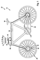
- Fig. 1 shows a vehicle according to the invention 22 with a vehicle brake unit 10 according to the invention in a schematic representation.
- the vehicle 22 is designed as a bicycle.
- the vehicle 22 is characterized by a training as a bicycle.
- the vehicle 22 includes a vehicle frame 24.
- the vehicle 22 includes two wheels 26, which are each attached to the vehicle frame 24.
- only one of the wheels 26 will be described and provided with reference numerals.
- the wheel 26 related features also refer to the other wheel 26.
- the vehicle 22 has a drive unit 28, by means of which the vehicle 22 is driven.
- the drive unit 28 is intended to be driven by a driver (not shown).
- the vehicle 22 is movable.
- the vehicle 22 has a vehicle saddle 30 which is fixed to the vehicle frame 24.
- the vehicle seat 30 is provided as a seat for the driver.
- the vehicle 22 includes a vehicle handlebar 32 that is attached to the vehicle frame 24.
- the vehicle 22 on two handles 42 which are attached to the vehicle handlebar 32. From the two handles 42 in Fig. 1 and Fig. 2 is only one shown. In the following, only one of the two handles 42 will be described.
- the vehicle 22 comprises the vehicle brake unit 10, which has a brake adjustment unit 12, which is intended to set a braking effect in a targeted manner.
- the vehicle brake unit 10 is designed as a two-wheeled brake unit.
- the vehicle brake unit 10 is equipped with a brake unit 20, which is designed as a disc brake.
- the brake unit 20 is disposed at a pivot point of the wheel 26 on the vehicle frame 24.
- the vehicle brake unit 10 comprises two brake lever units 34, which are provided for actuating the brake unit 20. Of the brake lever units 34 is in Fig. 1 and Fig. 2 only one shown. In the following, only one of the two brake lever units 34 will be described.
- the brake lever unit 34 is connected to the brake unit 20 by means of a brake line 36.
- the vehicle brake unit 10 comprises the brake line 36.
- the brake line 36 has a brake line train and a brake line sheathing (cf. Fig. 2 ).
- the Brems effetszugummantelung is intended to protect the Brems effetszug against external influences protective.
- the brake pipe train is provided for transmitting a braking force from the brake lever unit 34 to the brake unit 20.
- the brake lever unit 34 has a brake lever unit housing 38.
- the brake lever unit 34 has a brake lever element 40, which is mounted pivotably about a pivot axis 44 on the brake lever unit housing 38.
- the brake lever unit housing 38 has a brake lever recess, which is arranged both on a side facing the vehicle driver 32 and on a side of the brake lever element 40 facing away from the vehicle driver 32.
- the brake lever member 40 is easily pivotable about the pivot axis 44.
- the brake lever member 40 is provided for operation by the driver.
- the brake lever member 40 is provided to transmit the braking force exerted by the operation and acting on the brake lever member 40 to the brake unit 20.
- the brake lever member 40 is provided to transmit the braking force exerted by the operation and acting on the brake lever member 40 by means of the brake pipe 36 to the brake unit 20.
- the brake lever element 40 is provided to be pivoted about the pivot axis 44 in the direction of the handle 42 during operation with a brake lever unit housing 38 facing away from the end.
- the brake adjusting unit 12 has an actuating unit 16, which is provided to set the braking effect partially automatically depending on a parameter.
- the operating unit 16 has a wheel sensor unit 46, which is provided to measure a rotational speed of the wheel 26.
- the wheel sensor unit 46 is arranged on the brake unit 20.
- the actuating unit 16 is provided to determine a slip of the wheel 26 by means of the wheel sensor unit 46.
- the actuating unit 16 is provided to detect a blockage of the wheel 26 on the basis of the slip.
- the characteristic is formed as the blocking of the wheel 26.
- the wheel sensor unit 46 is provided to transmit the measured data wirelessly to the actuator unit 16.
- the brake adjusting unit 12 comprises a control unit 48, which is provided to regulate the braking effect in a continuously ongoing control circuit targeted.
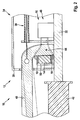
- Fig. 2 shows a section of the vehicle brake unit 10 according to the invention Fig. 1 in a greatly enlarged sectional view.
- the brake adjusting unit 12 has a braking element 14, which is intended to contribute to a setting of the braking effect by a change in the material properties.
- the brake element 14 is provided for generating a counterforce, which is directed against the braking force. The contribution is designed as the counterforce.
- the material property change of the brake member 14 is formed as a rigidity change.
- the brake element 14 is disposed in the brake lever unit housing 38. Namely, the brake element 14 is disposed on a wall of the brake lever unit housing 38. With a side facing away from the wall of the brake lever unit housing 38, the brake member 14 is in direct contact with the brake lever member 40.
- the brake member 14 is disposed in a relaxed state of the vehicle brake unit 10 in a relaxed state between the brake lever unit housing 38 and the brake lever member 40.
- the powerless state is defined as an absence of external forces acting on the vehicle brake unit 10, especially as an absence of the braking force.
- the brake element 14 comprises a magneto-rheological material.
- the brake element 14 is intended to have the material property change by means of an external stimulus.
- the brake element 14 is provided to undo the material property change after removal of the external stimulus.
- the brake element 14 is intended to remember its initial state. Namely, the braking member 14 is provided to return to its original state after removal of the external stimulus.
- the magneto-rheological material comprises a magneto-rheological elastomer.
- the brake adjusting unit 12 is provided to generate the external stimulus.
- the brake adjusting unit 12 has a field generating unit 18 which is provided to generate a field for attaining the material property change of the braking member 14.
- the field generation unit 18 is in Fig. 2 shown only schematically in the form of two line elements.
- the field generation unit 18 is disposed in the brake lever unit housing 38.
- the field generation unit 18 is disposed on two opposite sides of the brake member 14.
- the field generation unit 18 is arranged on the two opposite sides of the brake element 14 with some distance from the brake element 14. As a result, a change in shape of the brake element 14 can be realized without difficulty.
- the field generation unit 18 has a recess in a region of the brake lever element 40.
- the field generation unit 18 is intended to generate a magnetic field.
- the field is designed as the magnetic field.
- the brake adjusting unit 12 is provided to operate the field generating unit 18 by means of the control unit 48.
- the field generation unit 18 is connected to the control unit 48 by means of an electrical line.
- the field generation unit 18 comprises electromagnets which are intended to generate the field.
- the field generation unit 18 is intended to generate a homogeneous field in the brake element 14.
- the electromagnets are connected to generate the homogeneous field respectively corresponding to the electrical line.
- the brake adjusting unit 12 further includes an accumulator which is provided to supply the brake adjusting unit 12 with electric power.
- the accumulator is integrated in the control unit 48.
- the Bremseinstelltechnik 12 is provided to be powered by a dynamo with electrical energy.
- the vehicle driver exerts the braking force by the driver actuating the brake lever element 40.
- the brake unit 20 is activated and the vehicle 22 braked.
- the wheel sensor unit 46 measures the blocking case of the wheel 26, it transmits the measured data to the brake setting unit 12.
- the brake setting unit 12 adjusts the braking effect in accordance with the transmitted data.
- the brake adjusting unit 12 is provided to control the braking effect by means of the control unit 48 in a continuously ongoing control circuit targeted
Landscapes
- Engineering & Computer Science (AREA)
- Mechanical Engineering (AREA)
- Transportation (AREA)
- Regulating Braking Force (AREA)
- Tires In General (AREA)
- Braking Arrangements (AREA)
Description
- In der JPS59164427 ist bereits eine Fahrzeugbremseinheit, insbesondere eine Zweiradbremseinheit, die zumindest eine Bremseinstelleinheit aufweist, die dazu vorgesehen ist, eine Bremswirkung gezielt einzustellen, mit den Merkmalen des Oberbegriffes des Anspruchs 1, vorgeschlagen worden.
- Die Erfindung geht aus von einer Fahrzeugbremseinheit gemäß Anspruch 1, insbesondere einer Zweiradbremseinheit, die zumindest eine Bremseinstelleinheit aufweist, die dazu vorgesehen ist, eine Bremswirkung gezielt einzustellen.
- Es wird vorgeschlagen, dass die Bremseinstelleinheit zumindest ein Bremselement aufweist, das dazu vorgesehen ist, durch zumindest eine Materialeigenschaftsänderung zumindest einen Beitrag zu einer Einstellung, der Bremswirkung zu bewirken. Unter einer "Bremseinstelleinheit" soll insbesondere eine Einheit verstanden werden, die dazu vorgesehen ist, die Bremswirkung gezielt, vorzugsweise planmäßig, insbesondere bewusst, einzustellen. Insbesondere umfasst die Bremseinstelleinheit zumindest eine Einstelleinheit. Unter einer "Einstelleinheit" soll insbesondere eine Einheit mit einer Prozessoreinheit und mit einer Speichereinheit sowie mit einem in der Speichereinheit gespeicherten Betriebsprogramm verstanden werden. Grundsätzlich kann die Bremseinstelleinheit mehrere untereinander verbundene Einstelleinheiten aufweisen, die vorzugsweise dazu vorgesehen sind, über ein Bus-System, wie insbesondere ein CAN-Bus-System, miteinander zu kommunizieren. Insbesondere umfasst die Einstelleinheit zumindest eine Steuereinheit und/oder zumindest eine Regeleinheit. Unter einer "Steuereinheit" soll insbesondere eine Einheit verstanden werden, die dazu vorgesehen ist, einmalig die Bremswirkung zu beeinflussen und anschließend in dem beeinflussten Zustand zu halten. Unter einer "Regeteinheit" soll insbesondere eine Einheit verstanden werden, die dazu vorgesehen ist, einmalig die Bremswirkung zu beeinflussen, anschließend zu prüfen, ob die beeinflusste Bremswirkung eine gewünschte Wirkung erzielt und entsprechend einem Ergebnis der Prüfung die Bremswirkung erneut zu beeinflussen. Insbesondere ist die Regeleinheit dazu vorgesehen, die Bremswirkung in einem kontinuierlich andauernden Regelkreislauf zu regeln, insbesondere zu überwachen. Unter der Wendung, dass die Bremseinstelleinheit dazu vorgesehen ist, die Bremswirkung "gezielt" einzustellen, soll insbesondere verstanden werden, dass die Bremseinstelleinheit dazu vorgesehen ist, die Bremswirkung, vorzugsweise planmäßig, insbesondere bewusst, in eine bestimmte Richtung einzustellen, vorzugsweise zu beeinflussen, insbesondere zu regeln. Unter einem "Bremselement" soll insbesondere ein Element der Bremseinstelleinheit verstanden werden, das dazu vorgesehen ist, von der Bremseinstelleinheit eingestellt zu werden. Insbesondere ist das Bremselement dazu vorgesehen, durch die Materialeigenschaftsänderung den Beitrag zu der Einstellung der Bremswirkung zu bewirken. Beispielsweise ist das Bremselement zu einer Reduzierung eines Widerstands gegen eine, vorzugsweise von einem Fahrzeugführer ausgeübte, Bremskraft um mehr als 20 %, vorzugsweise um mehr als 40 % und insbesondere um mehr als 70 % vorgesehen. Insbesondere ist das Bremselement zu einer Erhöhung des Widerstands gegen die, vorzugsweise von dem Fahrzeugführer ausgeübte, Bremskraft um mehr als 20 %, vorzugsweise um mehr als 40 % und insbesondere um mehr als 70 % vorgesehen. Vorzugsweise ist das Bremselement zu einer Erzeugung einer Gegenkraft vorgesehen, welche entgegen der Bremskraft ausgerichtet ist und einen Betrag von mehr als 10 N, vorzugsweise von mehr als 20 N und insbesondere von mehr als 40 N aufweist. Insbesondere ist der Beitrag als eine Gegenkraft ausgebildet. Unter einer "Materialeigenschaftsänderung" eines Elements, insbesondere des Bremselements, soll insbesondere eine Änderung zumindest eines physikalischen und/oder chemischen und/oder geometrischen Parameters verstanden werden. Beispielsweise ist der Parameter als eine Dichte, ein Brechungsindex, eine Gitter-struktur und/oder eine Geometrie ausgebildet. Ebenfalls denkbar sind weitere, einem Fachmann als sinnvoll erscheinende Parameter. Durch eine erfindungsgemäße Ausgestaltung kann vorteilhaft eine gezielte Einstellung der Bremswirkung erreicht und damit eine Sicherheit für einen Fahrzeugführer eines die Fahrzeugbremseinheit umfassenden Fahrzeugs erhöht werden.
- Ferner wird vorgeschlagen, dass die Bremseinstelleinheit zumindest eine Betätigungseinheit aufweist, die dazu vorgesehen ist, die Bremswirkung zumindest teilweise selbsttätig abhängig von zumindest einer Kenngröße einzustellen. Beispielsweise ist denkbar, dass die Betätigungseinheit zumindest einen Regensensor aufweist und dazu vorgesehen ist, bei Regen die Bremswirkung einzustellen. Insbesondere weist die Betätigungseinheit zumindest eine Radsensoreinheit auf, die dazu vorgesehen ist, zumindest eine Drehzahl eines Rads, vorzugsweise eines Rads zumindest eines die Fahrzeugbremseinheit aufweisenden Fahrzeugs, zu messen. Vorzugsweise ist die Betätigungseinheit dazu vorgesehen, mittels der Radsensoreinheit zumindest einen Schlupf des Rads zu bestimmen. Insbesondere ist die Betätigungseinheit dazu vorgesehen, anhand des Schlupfs ein Blockieren des Rads zu erkennen. Vorzugsweise ist die Kenngröße als das Blockieren des Rads ausgebildet. Unter der Wendung, dass die Betätigungseinheit dazu vorgesehen ist, die Bremswirkung "selbsttätig" abhängig von der Kenngröße einzustellen, soll insbesondere verstanden werden, dass die Betätigungseinheit dazu vorgesehen ist, die Bremswirkung von sich aus abhängig von der Kenngröße einzustellen. Insbesondere ist die Betätigungseinheit dazu vorgesehen, die Bremswirkung unter Vermeidung einer Variation der, vorzugsweise von dem Fahrzeugführer ausgeübten, Bremskraft einzustellen. Unter der Wendung, dass die Betätigungseinheit dazu vorgesehen ist, die Bremswirkung "zumindest teilweise selbsttätig" abhängig von der Kenngröße einzustellen, soll insbesondere verstanden werden, dass die Betätigungseinheit dazu vorgesehen ist, bei Auftreten der, vorzugsweise von dem Fahrzeugführer ausgeübten, Bremskraft die Bremswirkung von sich aus abhängig von der Kenngröße einzustellen. Durch eine erfindungsgemäße Ausgestaltung kann vorteilhaft die Bremswirkung unabhängig von äußeren Einflüssen, insbesondere unabhängig von der von dem Fahrzeugführer erzeugten Bremskraft, sicher und effektiv eingestellt werden.
- Zudem wird vorgeschlagen, dass die Materialeigenschaftsänderung des Bremselements zumindest als eine Steifigkeitsänderung ausgebildet ist. Insbesondere ist die Materialeigenschaftsänderung des Bremselements zumindest als eine Schersteifigkeitsänderung ausgebildet. Beispielsweise ist denkbar, dass das Bremselement dazu vorgesehen ist, durch ein Weicherstellen des Bremselements eine Reduzierung eines Widerstands gegen die Bremskraft um mehr als 20 %, vorzugsweise um mehr als 40 % und insbesondere um mehr als 70 % zu ermöglichen. Dabei ist das Bremselement als ein Bremsbelag ausgebildet und insbesondere in einem Bereich eines Rads eines Fahrzeugs angeordnet. Insbesondere ist das Bremselement dazu vorgesehen, durch ein Härterstellen des Bremselements eine Erhöhung des Widerstands gegen die Bremskraft um mehr als 20 %, vorzugsweise um mehr als 40 % und insbesondere um mehr als 70 % zu ermöglichen. Vorzugsweise ist das Bremselement dazu vorgesehen, eine Gegenkraft zu erzeugen, die entgegen der Bremskraft gerichtet ist. Insbesondere ist das Bremselement in einem Bereich zu einer Erzeugung der Bremskraft angeordnet. Vorzugsweise ist der Bereich zu der Erzeugung der Bremskraft als ein Bremshebel und/oder als ein Bremspedal ausgebildet. Insbesondere ist das Bremselement in einem Bereich einer Handbremsbetätigungseinheit, die zu der Erzeugung der Bremskraft vorgesehen ist, angeordnet. Unter einer "Steifigkeit" des Materials soll insbesondere eine Eigenschaft des Materials, insbesondere des Bremselements, verstanden werden, die einen Widerstand des Materials gegen Verformung beschreibt. Insbesondere ist die Steifigkeit als ein Widerstand gegen eine durch zumindest einen, vorzugsweise äußeren, Reiz aufgebrachte Verformung ausgebildet. Vorzugsweise ist der Reiz als eine Kraft und/oder als ein Drehmoment ausgebildet. Durch eine erfindungsgemäße Ausgestaltung kann vorteilhaft eine Wirkung der Bremskraft gezielt beeinflusst und damit die Bremswirkung in einer sicheren, zuverlässigen Weise eingestellt werden.
- Weiterhin wird vorgeschlagen, dass die Bremseinstelleinheit zumindest eine Felderzeugungseinheit aufweist, die dazu vorgesehen ist, zumindest ein Feld zu einer Erreichung der Materialeigenschaftsänderung des Bremselements zu erzeugen. Unter einer "Felderzeugungseinheit" soll insbesondere eine Einheit verstanden werden, die dazu vorgesehen ist, ein inneres und/oder ein äußeres Feld zu erzeugen. Insbesondere ist die Felderzeugungseinheit dazu vorgesehen, mittels des Felds zumindest ein Element, insbesondere das Bremselement, gezielt, vorzugsweise planmäßig, insbesondere bewusst, zu beeinflussen. Unter einem "inneren Feld" soll insbesondere ein Feld innerhalb des Elements verstanden werden. Unter einem "äußeren Feld" soll insbesondere ein Feld außerhalb des Elements verstanden werden. Insbesondere ist die Felderzeugungseinheit dazu vorgesehen, das äußere Feld außerhalb des Elements zu erzeugen. Durch eine erfindungsgemäße Ausgestaltung kann vorteilhaft die Materialeigenschaftsänderung des Bremselements durch ein Feld erzeugt werden, wodurch eine gezielte, sichere Einstellung der Materialeigenschaftsänderung des Bremselements ermöglicht werden kann.
- Ferner wird vorgeschlagen, dass das Feld als ein magnetisches Feld ausgebildet ist. Alternativ und/oder zusätzlich ist denkbar, dass das Feld als ein elektrisches Feld ausgebildet ist. Durch eine erfindungsgemäße Ausgestaltung kann vorteilhaft eine magnetische Eigenschaft des Bremselements gezielt zu einer sicheren Einstellung der Materialeigenschaftsänderung des Bremselements ausgenutzt werden.
- Zudem wird vorgeschlagen, dass das Bremselement zumindest ein magneto-rheologisches Material umfasst. Alternativ und/oder zusätzlich ist denkbar, dass das Bremselement zumindest ein elektro-rheologisches Material umfasst. Unter der Wendung, dass das Bremselement zumindest ein magneto-rheologisches Material umfasst, soll insbesondere verstanden werden, dass das Bremselement zu einem Massenanteil und/oder zu einem Volumenanteil von mehr als 70 %, vorzugsweise von mehr als 80 % und insbesondere von mehr als 90 % aus dem magneto-rheologischen Material ausgebildet ist. Unter einem "magneto-rheologischen Material" soll insbesondere eine Suspension von magnetischen Partikeln, vorzugsweise mit einer Größe in einem Bereich von einigen µm, in einem Träger verstanden werden. Insbesondere ist das magneto-rheologische Material dazu vorgesehen, zumindest eine, vorzugsweise rheologische, Materialeigenschaft bei Anlegen eines magnetischen Felds von weniger als 0,1 T, vorzugsweise von weniger als 0,01 T und insbesondere von weniger als 0,001 T, vorzugsweise rasch, insbesondere reversibel, zu verändern. Vorzugsweise ist eine Änderung der Materialeigenschaft durch eine Variation des Felds beeinflussbar. Insbesondere ist die Änderung der Materialeigenschaft proportional zu einer Stärke des angelegten Felds. Vorzugsweise sind bei Anlegen des Felds Materialeigenschaftsänderungen von mehreren hundert Prozent erreichbar. Insbesondere ist das magneto-rheologische Material dazu vorgesehen, nach Abschalten des angelegten Felds in seinen Ausgangszustand, insbesondere in seinen Zustand vor Anlegen des Felds, vorzugsweise rasch, zurückzukehren. Vorzugsweise ist die Materialeigenschaft als eine Form und/oder als eine Steifigkeit, vorzugsweise als eine Schersteifigkeit, des magneto-rheologischen Materials ausgebildet. Insbesondere sind die Partikel zu einem Volumenanteil zwischen 5 % und 50 % eines Gesamtvolumens des magnetorheologischen Materials in dem Träger dispergiert. Vorzugsweise sind die Partikel als ferromagnetische und/oder paramagnetische Partikel ausgebildet. Beispielsweise sind die Partikel als Eisen, Eisenoxid, Eisennitrid, Eisencarbid, Carbonyleisen, Nickel, Kobalt, Chromoxid und/oder eine Kombination zumindest eines der vorgenannten Materialien mit zumindest einem weiteren Material ausgebildet. Beispielsweise ist der Träger als Polyalphaolefine, Naturkautschuk, Silikon, Polybutadien, Polyethylen, Polyisopren und/oder eine Kombination zumindest eines der vorgenannten Materialien mit zumindest einem weiteren Element ausgebildet. Unter einer "Suspension" soll insbesondere ein, vorzugsweise heterogenes, Stoffgemisch aus zumindest einem Trägermaterial und in dem Trägermaterial verteilten Partikeln, vorzugsweise mit einer Partikelgröße von weniger als 100 µm, vorzugsweise von weniger als 50 µm und insbesondere von weniger als 10 µm, verstanden werden. Beispielsweise ist das Trägermaterial als eine Flüssigkeit oder ein Festkörper ausgebildet. Unter "rasch" soll insbesondere eine Zeitspanne von wenigen Millisekunden verstanden werden. Unter einem "elektro-rheologischen Material" soll insbesondere eine Suspension von elektrischen Partikeln, vorzugsweise mit einer Größe in einem Bereich von einigen µm, in einem Träger verstanden werden. Insbesondere ist das elektro-rheologische Material dazu vorgesehen, zumindest eine, vorzugsweise rheologische, Materialeigenschaft bei Anlegen eines elektrischen Felds von weniger als 200 V/m, vorzugsweise von weniger als 100 V/m und insbesondere von weniger als 50 V/m, vorzugsweise rasch, insbesondere reversibel, zu verändern. Vorzugsweise ist eine Änderung der Materialeigenschaft durch eine Variation des Felds beeinflussbar. Insbesondere ist die Änderung der Materialeigenschaft proportional zu einer Stärke des angelegten Felds. Vorzugsweise sind bei Anlegen des Felds Materialeigenschaftsänderungen von mehreren zehn Prozent erreichbar. Insbesondere ist das elektro-rheologische Material dazu vorgesehen, nach Abschalten des angelegten Felds in seinen Ausgangszustand, insbesondere in seinen Zustand vor Anlegen des Felds, vorzugsweise rasch, zurückzukehren. Vorzugsweise ist die Materialeigenschaft als eine Form und/oder als eine Steifigkeit, vorzugsweise als eine Schersteifigkeit, des elektro-rheologischen Materials ausgebildet. Insbesondere sind die Partikel zu einem Volumenanteil zwischen 5 % und 50 % eines Gesamtvolumens des elektro-rheologischen Materials in dem Träger dispergiert. Durch eine erfindungsgemäße Ausgestaltung kann vorteilhaft das Bremselement ein Material umfassen, das in einer einfachen Weise gezielt beeinflussbar ist und auf die Beeinflussung vorhersagbar reagiert. Dadurch kann vorteilhaft eine Sicherheit der Fahrzeugbremseinheit weiter erhöht werden.
- Weiterhin wird vorgeschlagen, dass das magneto-rheologische Material zumindest ein magneto-rheologisches Elastomer umfasst. Alternativ oder zusätzlich ist denkbar, dass das elektro-rheologische Material zumindest ein elektro-rheologisches Elastomer umfasst. Unter einem "magneto-rheologischen Elastomer" soll insbesondere ein magneto-rheologisches Material verstanden werden, bei welchem der Träger als ein Elastomer ausgebildet ist. Unter einem "elektro-rheologischen Elastomer" soll insbesondere ein elektro-rheologisches Material verstanden werden, bei welchem der Träger als ein Elastomer ausgebildet ist. Durch eine erfindungsgemäße Ausgestaltung kann vorteilhaft eine spezielle, für vorliegende Bedürfnisse besonders gut geeignete Form des magneto-rheologischen Materials verwendet werden.
- Ferner wird vorgeschlagen, dass die Fahrzeugbremseinheit zumindest eine Bremseinheit, die als eine Scheibenbremse ausgebildet ist, aufweist. Durch eine erfindungsgemäße Ausgestaltung kann vorteilhaft eine langlebige Bremseinheit erreicht werden. Zudem kann durch eine Ausbildung der Bremseinheit als Scheibenbremse eine Bremswirkung erhöht und damit ein sicheres, schnelleres Abbremsen gewährleistet werden.
- Zudem wird ein Fahrzeug, insbesondere ein Zweirad, mit zumindest einer erfindungsgemäßen Fahrzeugbremseinheit vorgeschlagen. Durch eine erfindungsgemäße Ausgestaltung kann vorteilhaft ein Fahrzeug mit der erfindungsgemäßen Fahrzeugbremseinheit ausgestattet werden, wodurch ein sicheres Fahrzeug erreicht werden kann.
- Weiterhin wird vorgeschlagen, dass das Fahrzeug eine Ausbildung als Fahrrad umfasst. Alternativ ist denkbar, dass das Fahrzeug eine Ausbildung als Motorrad umfasst. Durch eine erfindungsgemäße Ausgestaltung kann vorteilhaft ein Fahrrad mit einer besonders zuverlässigen, sicheren Fahrzeugbremseinheit erreicht werden.
- Ferner wird ein Verfahren gemäß Anspruch 11 zu einem Betreiben zumindest einer erfindungsgemäßen Fahrzeugbremseinheit, bei dem das Bremselement der Bremseinstelleinheit durch zumindest eine Materialeigenschaftsänderung zumindest einen Beitrag zu einer Einstellung der Bremswirkung bewirkt, vorgeschlagen. Durch eine erfindungsgemäße Ausgestaltung kann vorteilhaft die erfindungsgemäße Fahrzeugbremseinheit in einer korrekten, sicheren, reproduzierbaren Weise betrieben werden und damit eine Sicherheit weiter erhöht werden.
- Die erfindungsgemäße Fahrzeugbremseinheit soll hierbei nicht auf die oben beschriebene Anwendung und Ausführungsform beschränkt sein. Insbesondere kann die erfindungsgemäße Fahrzeugbremseinheit zu einer Erfüllung einer hierin beschriebenen Funktionsweise eine von einer hierin genannten Anzahl von einzelnen Elementen, Bauteilen und Einheiten abweichende Anzahl aufweisen.
- Weitere Vorteile ergeben sich aus der folgenden Zeichnungsbeschreibung. In der Zeichnung ist ein Ausführungsbeispiel der Erfindung dargestellt. Die Zeichnung, die Beschreibung und die Ansprüche enthalten zahlreiche Merkmale in Kombination. Der Fachmann wird die Merkmale zweckmäßigerweise auch einzeln betrachten und zu sinnvollen weiteren Kombinationen zusammenfassen.
- Es zeigen:
- Fig. 1
- ein erfindungsgemäßes Fahrzeug mit einer erfindungsgemäßen Fahrzeugbremseinheit in einer schematischen Darstellung und
- Fig. 2
- einen Ausschnitt der erfindungsgemäßen Fahrzeugbremseinheit aus
Fig. 1 in einer stark vergrößerten Schnittdarstellung. -
Fig. 1 zeigt ein erfindungsgemäßes Fahrzeug 22 mit einer erfindungsgemäßen Fahrzeugbremseinheit 10 in einer schematischen Darstellung. Im Folgenden wird lediglich auf für die vorliegende Erfindung wesentliche Merkmale detailliert eingegangen. Das Fahrzeug 22 ist als ein Zweirad ausgebildet. Im vorliegenden Ausführungsbeispiel ist das Fahrzeug 22 gekennzeichnet durch eine Ausbildung als Fahrrad. Das Fahrzeug 22 umfasst einen Fahrzeugrahmen 24. Zudem umfasst das Fahrzeug 22 zwei Räder 26, die jeweils an dem Fahrzeugrahmen 24 befestigt sind. Im Folgenden wird lediglich eines der Räder 26 beschrieben und mit Bezugszeichen versehen. Analog hierzu beziehen sich im Folgenden mit dem Rad 26 in Verbindung stehende Merkmale gleichfalls auf das weitere Rad 26. Das Fahrzeug 22 weist eine Antriebseinheit 28 auf, mittels der das Fahrzeug 22 antreibbar ist. Die Antriebseinheit 28 ist dazu vorgesehen, von einem Fahrzeugführer (nicht dargestellt) angetrieben zu werden. Mittels einer von dem Fahrzeugführer auf die Antriebseinheit 28 aufgebrachten Energie ist das Fahrzeug 22 bewegbar. Das Fahrzeug 22 weist einen Fahrzeugsattel 30 auf, der an dem Fahrzeugrahmen 24 befestigt ist. Der Fahrzeugsattel 30 ist als eine Sitzgelegenheit für den Fahrzeugführer vorgesehen. Das Fahrzeug 22 umfasst einen Fahrzeuglenker 32, der an dem Fahrzeugrahmen 24 befestigt ist. Weiterhin weist das Fahrzeug 22 zwei Handgriffe 42 auf, die an dem Fahrzeuglenker 32 angebracht sind. Von den beiden Handgriffen 42 inFig. 1 undFig. 2 ist lediglich einer dargestellt. Im Folgenden wird lediglich einer der beiden Handgriffe 42 beschrieben. - Das Fahrzeug 22 umfasst die Fahrzeugbremseinheit 10, die eine Bremseinstelleinheit 12 aufweist, die dazu vorgesehen ist, eine Bremswirkung gezielt einzustellen. Die Fahrzeugbremseinheit 10 ist als eine Zweiradbremseinheit ausgebildet. Ausgestattet ist die Fahrzeugbremseinheit 10 mit einer Bremseinheit 20, die als eine Scheibenbremse ausgebildet ist. Die Bremseinheit 20 ist an einer Anlenkstelle des Rads 26 an dem Fahrzeugrahmen 24 angeordnet. Die Fahrzeugbremseinheit 10 umfasst zwei Bremshebeleinheiten 34, die zu einer Betätigung der Bremseinheit 20 vorgesehen sind. Von den Bremshebeleinheiten 34 ist in
Fig. 1 undFig. 2 jeweils lediglich eine dargestellt. Im Folgenden wird lediglich eine der beiden Bremshebeleinheiten 34 beschrieben. Die Bremshebeleinheit 34 ist mittels einer Bremsleitung 36 mit der Bremseinheit 20 verbunden. Die Fahrzeugbremseinheit 10 umfasst die Bremsleitung 36. Die Bremsleitung 36 weist einen Bremsleitungszug sowie eine Bremsleitungszugummantelung auf (vgl.Fig. 2 ). Die Bremsleitungszugummantelung ist dazu vorgesehen, den Bremsleitungszug vor äußeren Einflüssen schützend zu lagern. Der Bremsleitungszug ist zu einer Übertragung einer Bremskraft von der Bremshebeleinheit 34 an die Bremseinheit 20 vorgesehen. - Die Bremshebeleinheit 34 weist ein Bremshebeleinheitengehäuse 38 auf. Zudem weist die Bremshebeleinheit 34 ein Bremshebelelement 40 auf, das um eine Schwenkachse 44 schwenkbar an dem Bremshebeleinheitengehäuse 38 gelagert ist. In einem Bereich, in welchem das Bremshebelelement 40 das Bremshebeleinheitengehäuse 38 durchquert, weist das Bremshebeleinheitengehäuse 38 eine Bremshebelaussparung auf, die sowohl an einer dem Fahrzeuglenker 32 zuweisenden Seite als auch an einer dem Fahrzeuglenker 32 abweisenden Seite des Bremshebelelements 40 angeordnet ist. Dadurch ist das Bremshebelelement 40 problemlos um die Schwenkachse 44 schwenkbar. Das Bremshebelelement 40 ist zu einer Betätigung durch den Fahrzeugführer vorgesehen. Das Bremshebelelement 40 ist dazu vorgesehen, die durch die Betätigung ausgeübte und auf das Bremshebelelement 40 einwirkende Bremskraft an die Bremseinheit 20 zu übertragen. Und zwar ist das Bremshebelelement 40 dazu vorgesehen, die durch die Betätigung ausgeübte und auf das Bremshebelelement 40 einwirkende Bremskraft mittels der Bremsleitung 36 an die Bremseinheit 20 zu übertragen. Das Bremshebelelement 40 ist dazu vorgesehen, bei der Betätigung mit einem dem Bremshebeleinheitengehäuse 38 abweisenden Ende um die Schwenkachse 44 in Richtung des Handgriffs 42 verschwenkt zu werden.
- Die Bremseinstelleinheit 12 weist eine Betätigungseinheit 16 auf, die dazu vorgesehen ist, die Bremswirkung teilweise selbsttätig abhängig von einer Kenngröße einzustellen. Die Betätigungseinheit 16 weist eine Radsensoreinheit 46 auf, die dazu vorgesehen ist, eine Drehzahl des Rads 26 zu messen. Im vorliegenden Ausführungsbeispiel ist die Radsensoreinheit 46 an der Bremseinheit 20 angeordnet. Die Betätigungseinheit 16 ist dazu vorgesehen, mittels der Radsensoreinheit 46 einen Schlupf des Rads 26 zu bestimmen. Die Betätigungseinheit 16 ist dazu vorgesehen, anhand des Schlupfs ein Blockieren des Rads 26 zu erkennen. Vorzugsweise ist die Kenngröße als das Blockieren des Rads 26 ausgebildet. Die Radsensoreinheit 46 ist dazu vorgesehen, die gemessenen Daten drahtlos an die Betätigungseinheit 16 zu übermitteln. Die Bremseinstelleinheit 12 umfasst eine Regeleinheit 48, die dazu vorgesehen ist, die Bremswirkung in einem kontinuierlich andauernden Regelkreislauf gezielt zu regeln.
-
Fig. 2 zeigt einen Ausschnitt der erfindungsgemäßen Fahrzeugbremseinheit 10 ausFig. 1 in einer stark vergrößerten Schnittdarstellung. Die Bremseinstelleinheit 12 weist ein Bremselement 14 auf, das dazu vorgesehen ist, durch eine Materialeigenschaftsänderung einen Beitrag zu einer Einstellung der Bremswirkung zu bewirken. Das Bremselement 14 ist zu einer Erzeugung einer Gegenkraft, die entgegen der Bremskraft gerichtet ist, vorgesehen. Der Beitrag ist als die Gegenkraft ausgebildet. Die Materialeigenschaftsänderung des Bremselements 14 ist als eine Steifigkeitsänderung ausgebildet. Im vorliegenden Ausführungsbeispiel ist das Bremselement 14 in dem Bremshebeleinheitengehäuse 38 angeordnet. Und zwar ist das Bremselement 14 an einer Wandung des Bremshebeleinheitengehäuses 38 angeordnet. Mit einer der Wandung des Bremshebeleinheitengehäuses 38 abweisenden Seite ist das Bremselement 14 in einem direkten Kontakt mit dem Bremshebelelement 40. Das Bremselement 14 ist in einem kraftlosen Zustand der Fahrzeugbremseinheit 10 in einem entspannten Zustand zwischen dem Bremshebeleinheitengehäuse 38 sowie dem Bremshebelelement 40 angeordnet. Der kraftlose Zustand ist definiert als eine Abwesenheit äußerer, auf die Fahrzeugbremseinheit 10 einwirkender Kräfte, vor allem als eine Abwesenheit der Bremskraft. - Das Bremselement 14 umfasst ein magneto-rheologisches Material. Das Bremselement 14 ist dazu vorgesehen, mittels eines äußeren Reizes die Materialeigenschaftsänderung aufzuweisen. Zudem ist das Bremselement 14 dazu vorgesehen, nach einem Entfernen des äußeren Reizes die Materialeigenschaftsänderung rückgängig zu machen. Das Bremselement 14 ist dazu vorgesehen, sich an seinen Ausgangszustand zu erinnern. Und zwar ist das Bremselement 14 dazu vorgesehen, nach dem Entfernen des äußeren Reizes in seinen Ausgangzustand zurückzukehren. Das magneto-rheologische Material umfasst ein magneto-rheologisches Elastomer.
- Die Bremseinstelleinheit 12 ist dazu vorgesehen, den äußeren Reiz zu erzeugen. Und zwar weist die Bremseinstelleinheit 12 eine Felderzeugungseinheit 18 auf, die dazu vorgesehen ist, ein Feld zu einer Erreichung der Materialeigenschaftsänderung des Bremselements 14 zu erzeugen. Die Felderzeugungseinheit 18 ist in
Fig. 2 lediglich schematisch in Form zweier Leitungselemente dargestellt. Die Felderzeugungseinheit 18 ist in dem Bremshebeleinheitengehäuse 38 angeordnet. Und zwar ist die Felderzeugungseinheit 18 an zwei einander gegenüberliegenden Seiten des Bremselements 14 angeordnet. Die Felderzeugungseinheit 18 ist an den zwei einander gegenüberliegenden Seiten des Bremselements 14 mit etwas Abstand zu dem Bremselement 14 angeordnet. Dadurch ist eine Formänderung des Bremselements 14 problemlos realisierbar. Die Felderzeugungseinheit 18 weist in einem Bereich des Bremshebelelements 40 eine Aussparung auf. Dadurch ist das Bremshebelelement 40 problemlos um die Schwenkachse 44 schwenkbar. Die Felderzeugungseinheit 18 ist dazu vorgesehen, ein magnetisches Feld zu erzeugen. Das Feld ist als das magnetische Feld ausgebildet. Die Bremseinstelleinheit 12 ist dazu vorgesehen, die Felderzeugungseinheit 18 mittels der Regeleinheit 48 zu betreiben. Die Felderzeugungseinheit 18 ist mittels einer elektrischen Leitung mit der Regeleinheit 48 verbunden. Die Felderzeugungseinheit 18 umfasst Elektromagnete, die dazu vorgesehen sind, das Feld zu erzeugen. Die Felderzeugungseinheit 18 ist dazu vorgesehen, ein homogenes Feld in dem Bremselement 14 zu erzeugen. Die Elektromagnete sind zu einer Erzeugung des homogenen Felds entsprechend jeweils mit der elektrischen Leitung verbunden. Die Bremseinstelleinheit 12 umfasst ferner einen Akkumulator, der dazu vorgesehen ist, die Bremseinstelleinheit 12 mit elektrischer Energie zu versorgen. Der Akkumulator ist in der Regeleinheit 48 integriert. Alternativ ist denkbar, dass die Bremseinstelleinheit 12 dazu vorgesehen ist, mittels eines Dynamos mit elektrischer Energie versorgt zu werden. - Es ist ein Verfahren zu einem Betreiben der Fahrzeugbremseinheit 10, bei dem das Bremselement 14 der Bremseinstelleinheit 12 durch die Materialeigenschaftsänderung den Beitrag zu der Einstellung der Bremswirkung bewirkt, vorgesehen. In einem ersten Verfahrensschritt übt der Fahrzeugführer die Bremskraft aus, indem der Fahrzeugführer das Bremshebelelement 40 betätigt. Durch die Bremskraft wird die Bremseinheit 20 aktiviert und das Fahrzeug 22 abgebremst. Misst die Radsensoreinheit 46 den Blockierfall des Rads 26, so übermittelt sie die gemessenen Daten an die Bremseinstelleinheit 12. Die Bremseinstelleinheit 12 stellt entsprechend den übermittelten Daten die Bremswirkung ein. Die Bremseinstelleinheit 12 ist dazu vorgesehen, die Bremswirkung mittels der Regeleinheit 48 in einem kontinuierlich andauernden Regelkreislauf gezielt zu regeln
Claims (11)
- Fahrzeugbremseinheit, insbesondere Zweiradbremseinheit, die zumindest eine Bremseinstelleinheit (12) aufweist, die dazu vorgesehen ist, eine Bremswirkung gezielt einzustellen, wobei die Bremseinstelleinheit (12) zumindest ein Bremselement (14) aufweist, das dazu vorgesehen ist, durch zumindest eine Materialeigenschaftsänderung zumindest einen Beitrag zu einer Einstellung der Bremswirkung zu bewirken, dadurch gekennzeichnet, dass das Bremselement (14) in einem Bremshebeleinheitengehäuse (38) einer Bremshebeleinheit (34) angeordnet ist, wobei das Bremselement (14) zur Erzeugung einer Bremskraft vorgesehen ist.
- Fahrzeugbremseinheit nach Anspruch 1, dadurch gekennzeichnet, dass die Bremseinstelleinheit (12) zumindest eine Betätigungseinheit (16) aufweist, die dazu vorgesehen ist, die Bremswirkung zumindest teilweise selbsttätig abhängig von zumindest einer Kenngröße einzustellen.
- Fahrzeugbremseinheit nach einem der vorhergehenden Ansprüche, dadurch gekennzeichnet, dass die Materialeigenschaftsänderung des Bremselements (14) zumindest als eine Steifigkeitsänderung ausgebildet ist.
- Fahrzeugbremseinheit nach einem der vorhergehenden Ansprüche, dadurch gekennzeichnet, dass die Bremseinstelleinheit (12) zumindest eine Felderzeugungseinheit (18) aufweist, die dazu vorgesehen ist, zumindest ein Feld zu einer Erreichung der Materialeigenschaftsänderung des Bremselements (14) zu erzeugen.
- Fahrzeugbremseinheit nach Anspruch 4, dadurch gekennzeichnet, dass das Feld als ein magnetisches Feld ausgebildet ist.
- Fahrzeugbremseinheit nach einem der vorhergehenden Ansprüche, dadurch gekennzeichnet, dass das Bremselement (14) zumindest ein magneto-rheologisches Material umfasst.
- Fahrzeugbremseinheit nach Anspruch 6, dadurch gekennzeichnet, dass das magneto-rheologische Material zumindest ein magneto-rheologisches Elastomer umfasst.
- Fahrzeugbremseinheit nach einem der vorhergehenden Ansprüche, gekennzeichnet durch zumindest eine Bremseinheit (20), die als eine Scheibenbremse ausgebildet ist.
- Fahrzeug, insbesondere Zweirad, mit zumindest einer Fahrzeugbremseinheit (10) nach einem der Ansprüche 1 bis 8.
- Fahrzeug nach Anspruch 9, gekennzeichnet durch eine Ausbildung als Fahrrad.
- Verfahren zu einem Betreiben zumindest einer Fahrzeugbremseinheit (10) nach Anspruch 1, bei dem das Bremselement (14) der Bremseinstelleinheit (12) durch zumindest eine Materialeigenschaftsänderung zumindest einen Beitrag zu einer Einstellung der Bremswirkung bewirkt.
Applications Claiming Priority (1)
| Application Number | Priority Date | Filing Date | Title |
|---|---|---|---|
| DE201210224382 DE102012224382A1 (de) | 2012-12-27 | 2012-12-27 | Fahrzeugbremseinheit |
Publications (2)
| Publication Number | Publication Date |
|---|---|
| EP2749483A1 EP2749483A1 (de) | 2014-07-02 |
| EP2749483B1 true EP2749483B1 (de) | 2016-09-21 |
Family
ID=49666983
Family Applications (1)
| Application Number | Title | Priority Date | Filing Date |
|---|---|---|---|
| EP13193685.8A Not-in-force EP2749483B1 (de) | 2012-12-27 | 2013-11-20 | Fahrzeugbremseinheit |
Country Status (3)
| Country | Link |
|---|---|
| EP (1) | EP2749483B1 (de) |
| CN (1) | CN103895632B (de) |
| DE (1) | DE102012224382A1 (de) |
Families Citing this family (12)
| Publication number | Priority date | Publication date | Assignee | Title |
|---|---|---|---|---|
| DE102013213413A1 (de) * | 2013-07-09 | 2015-01-15 | Robert Bosch Gmbh | Aktuatorvorrichtung für eine Bremse eines Fahrzeugs, Fahrzeug sowie Verfahren zum Aktuieren einer Bremse eines Fahrzeugs |
| EP3088263B1 (de) * | 2015-04-28 | 2017-12-20 | Bitron S.p.A. | Pedalsteuerungsvorrichtung, insbesondere für ein motorfahrzeug |
| CN107850148B (zh) * | 2015-07-29 | 2020-02-07 | 埃索欧耐迪克超动力 | 使用磁流变流体离合器设备的手动致动式制动系统 |
| DE102019203840A1 (de) * | 2019-03-21 | 2020-09-24 | Zf Friedrichshafen Ag | Bedienvorrichtung, Fahrzeug und Verfahren zum Betreiben eines Fahrzeugs |
| TWI710495B (zh) * | 2019-04-03 | 2020-11-21 | 臻錄貿易有限公司 | 把手結構 |
| DE102019219395A1 (de) * | 2019-12-12 | 2021-06-17 | Zf Friedrichshafen Ag | Bedienvorrichtung, Fahrzeug und Verfahren zum Betreiben eines Fahrzeugs |
| DE102022212477A1 (de) * | 2022-11-23 | 2024-05-23 | Zf Friedrichshafen Ag | Bedieneinrichtung für einen Tretlagerantrieb eines Elektrofahrrades, Verfahren zur Ansteuerung des Tretlagerantriebs sowie Elektrofahrrad |
| DE102023208253A1 (de) * | 2023-08-29 | 2024-08-14 | Zf Friedrichshafen Ag | Bremssystem für ein Fahrrad oder Motorrad |
| DE102023208260A1 (de) * | 2023-08-29 | 2024-05-29 | Zf Friedrichshafen Ag | Bremssystem für ein Fahrrad |
| DE102023208255A1 (de) * | 2023-08-29 | 2024-05-29 | Zf Friedrichshafen Ag | Bremssystem für ein Fahrrad |
| DE102023208254A1 (de) * | 2023-08-29 | 2024-08-14 | Zf Friedrichshafen Ag | Bremssystem für ein Fahrrad |
| DE102023208259A1 (de) * | 2023-08-29 | 2024-06-06 | Zf Friedrichshafen Ag | Bremssystem für ein Fahrrad |
Family Cites Families (11)
| Publication number | Priority date | Publication date | Assignee | Title |
|---|---|---|---|---|
| JPS59164424A (ja) * | 1983-03-05 | 1984-09-17 | Magune Kk | 自転車用無接触磁性流体制動装置 |
| DE3431823A1 (de) * | 1984-08-30 | 1986-03-13 | Alfred Teves Gmbh, 6000 Frankfurt | Servoeinrichtung, insbesondere fuer eine kraftfahrzeug-bremsanlage |
| DE19848186A1 (de) * | 1998-10-20 | 2000-04-27 | Volkswagen Ag | Pedaleinrichtung |
| KR100381818B1 (ko) * | 1999-10-15 | 2003-04-26 | 한국과학기술원 | 간단한 구조의 에너지공급부를 구비한 자기유변유체브레이크 및 그러한 자기유변유체브레이크를 구비한 회전기계 |
| DE10015714A1 (de) * | 2000-03-29 | 2001-10-04 | Bayerische Motoren Werke Ag | Elektromechanische Fahrzeug-Bremsanlage |
| KR20050023914A (ko) * | 2003-09-03 | 2005-03-10 | 현대자동차주식회사 | 회전형 엠알 감쇠기를 이용한 전동식 브레이크용 페달시뮬레이터 |
| DE102006031738A1 (de) * | 2006-07-10 | 2008-01-17 | Kastriot Merlaku | Brems-System für Fahrzeuge oder Maschinen aller Art |
| DE102006031855A1 (de) * | 2006-07-10 | 2008-01-17 | Kastriot Merlaku | Brems-Vorrichtung für einspurige Fahrzeuge, vorzugsweise für Fahrräder oder Motorräder |
| KR20110095374A (ko) * | 2008-12-18 | 2011-08-24 | 로베르트 보쉬 게엠베하 | 브레이크 부스터 |
| DE102010060879A1 (de) * | 2010-11-30 | 2012-05-31 | Dr. Ing. H.C. F. Porsche Aktiengesellschaft | Lagerbüchse |
| CN202326834U (zh) * | 2011-11-03 | 2012-07-11 | 浙江师范大学 | 一种新型制动器 |
-
2012
- 2012-12-27 DE DE201210224382 patent/DE102012224382A1/de not_active Withdrawn
-
2013
- 2013-11-20 EP EP13193685.8A patent/EP2749483B1/de not_active Not-in-force
- 2013-12-26 CN CN201310729996.5A patent/CN103895632B/zh not_active Expired - Fee Related
Also Published As
| Publication number | Publication date |
|---|---|
| CN103895632A (zh) | 2014-07-02 |
| EP2749483A1 (de) | 2014-07-02 |
| CN103895632B (zh) | 2018-11-16 |
| DE102012224382A1 (de) | 2014-07-03 |
Similar Documents
| Publication | Publication Date | Title |
|---|---|---|
| EP2749483A1 (de) | Fahrzeugbremseinheit | |
| EP3380389B1 (de) | Feedback-aktuator für eine lenkeinrichtung | |
| EP3380390B1 (de) | Feedbackaktuator für eine steer-by-wire-lenkung | |
| DE60303081T2 (de) | Handradstellglied | |
| DE10113502A1 (de) | Gurtaufroller | |
| EP2487079B1 (de) | Verfahren zum Betreiben eines Kraftfahrzeugs bei Durchfahren einer Kurve | |
| EP2433604A2 (de) | Hilfsantriebsvorrichtung, Rollstuhl und Verfahren zur Ermittlung von physischen Leistungsdaten eines Rollstuhlfahrers | |
| EP3395660B1 (de) | Vorrichtung und verfahren zum regeln eines lenkwinkels bei einem zweiradlenker | |
| DE102013104748A1 (de) | Verstellanordnung für einen Kraftfahrzeugsitz | |
| EP1369763B9 (de) | Fahrpedal | |
| EP3148860A1 (de) | Lenkwelle für eine kraftfahrzeuglenkung | |
| DE102007009563A1 (de) | Bremshebelanordnung | |
| EP3795436A1 (de) | Druckmodulator für ein antiblockier-system eines fahrrads | |
| EP2738055A1 (de) | Antiblockier-Bremsanordnung für ein Fahrzeug, Fahrzeug sowie Verfahren zum Abbremsen eines Fahrzeugs | |
| EP3412926A1 (de) | Planetenrad-getriebeanordnung insbesondere für eine elektromechanische betriebsbremse oder eine elektromechanische parkbremse für ein kraftfahrzeug | |
| DE102005019316A1 (de) | Verfahren zur Erkennung eines von einem Fahrer verursachten Lenkeingriffs in ein Servolenksystem eines Kraftfahrzeugs | |
| DE102006002456B4 (de) | Bremsmomentensensor für Fahrzeugbremsen | |
| DE102022109052A1 (de) | Lenkvorgabeeinrichtung zum Vorgeben einer Lenkbewegung nach dem Steer-by-Wire-Konzept und Verfahren zum Betreiben einer Lenkvorgabeeinrichtung | |
| EP2433603A2 (de) | Hilfsantriebsvorrichtung, Rollstuhl und Verfahren zur Ermittlung der manuellen Antriebskraft eines Rollstuhlfahrers | |
| DE102009055366A1 (de) | Hydraulisches Bremssystem für ein Fahrrad | |
| EP1833697A1 (de) | Fahrzustandsüberwachungseinrichtung für ein kraftfahrzeug | |
| DE202007007739U1 (de) | Muskelgetriebenes Fahrzeug | |
| EP3975966B1 (de) | Vorrichtung zum bremsen einer rotationsbewegung eines rotationselementes und rollvorrichtung | |
| DE102018201599B4 (de) | Lenkvorrichtung für ein Fahrzeug und Fahrzeug | |
| EP3702257B1 (de) | Fahrzeug mit einem bedienelement zum beschleunigen und bremsen |
Legal Events
| Date | Code | Title | Description |
|---|---|---|---|
| 17P | Request for examination filed |
Effective date: 20131120 |
|
| AK | Designated contracting states |
Kind code of ref document: A1 Designated state(s): AL AT BE BG CH CY CZ DE DK EE ES FI FR GB GR HR HU IE IS IT LI LT LU LV MC MK MT NL NO PL PT RO RS SE SI SK SM TR |
|
| AX | Request for extension of the european patent |
Extension state: BA ME |
|
| PUAI | Public reference made under article 153(3) epc to a published international application that has entered the european phase |
Free format text: ORIGINAL CODE: 0009012 |
|
| R17P | Request for examination filed (corrected) |
Effective date: 20150105 |
|
| RBV | Designated contracting states (corrected) |
Designated state(s): AL AT BE BG CH CY CZ DE DK EE ES FI FR GB GR HR HU IE IS IT LI LT LU LV MC MK MT NL NO PL PT RO RS SE SI SK SM TR |
|
| GRAP | Despatch of communication of intention to grant a patent |
Free format text: ORIGINAL CODE: EPIDOSNIGR1 |
|
| INTG | Intention to grant announced |
Effective date: 20160419 |
|
| GRAS | Grant fee paid |
Free format text: ORIGINAL CODE: EPIDOSNIGR3 |
|
| GRAA | (expected) grant |
Free format text: ORIGINAL CODE: 0009210 |
|
| AK | Designated contracting states |
Kind code of ref document: B1 Designated state(s): AL AT BE BG CH CY CZ DE DK EE ES FI FR GB GR HR HU IE IS IT LI LT LU LV MC MK MT NL NO PL PT RO RS SE SI SK SM TR |
|
| REG | Reference to a national code |
Ref country code: GB Ref legal event code: FG4D Free format text: NOT ENGLISH |
|
| REG | Reference to a national code |
Ref country code: CH Ref legal event code: EP |
|
| REG | Reference to a national code |
Ref country code: AT Ref legal event code: REF Ref document number: 830794 Country of ref document: AT Kind code of ref document: T Effective date: 20161015 |
|
| REG | Reference to a national code |
Ref country code: IE Ref legal event code: FG4D Free format text: LANGUAGE OF EP DOCUMENT: GERMAN |
|
| REG | Reference to a national code |
Ref country code: DE Ref legal event code: R096 Ref document number: 502013004656 Country of ref document: DE |
|
| REG | Reference to a national code |
Ref country code: FR Ref legal event code: PLFP Year of fee payment: 4 |
|
| REG | Reference to a national code |
Ref country code: NL Ref legal event code: FP |
|
| REG | Reference to a national code |
Ref country code: LT Ref legal event code: MG4D |
|
| PG25 | Lapsed in a contracting state [announced via postgrant information from national office to epo] |
Ref country code: RS Free format text: LAPSE BECAUSE OF FAILURE TO SUBMIT A TRANSLATION OF THE DESCRIPTION OR TO PAY THE FEE WITHIN THE PRESCRIBED TIME-LIMIT Effective date: 20160921 Ref country code: NO Free format text: LAPSE BECAUSE OF FAILURE TO SUBMIT A TRANSLATION OF THE DESCRIPTION OR TO PAY THE FEE WITHIN THE PRESCRIBED TIME-LIMIT Effective date: 20161221 Ref country code: LT Free format text: LAPSE BECAUSE OF FAILURE TO SUBMIT A TRANSLATION OF THE DESCRIPTION OR TO PAY THE FEE WITHIN THE PRESCRIBED TIME-LIMIT Effective date: 20160921 Ref country code: FI Free format text: LAPSE BECAUSE OF FAILURE TO SUBMIT A TRANSLATION OF THE DESCRIPTION OR TO PAY THE FEE WITHIN THE PRESCRIBED TIME-LIMIT Effective date: 20160921 |
|
| PG25 | Lapsed in a contracting state [announced via postgrant information from national office to epo] |
Ref country code: LV Free format text: LAPSE BECAUSE OF FAILURE TO SUBMIT A TRANSLATION OF THE DESCRIPTION OR TO PAY THE FEE WITHIN THE PRESCRIBED TIME-LIMIT Effective date: 20160921 Ref country code: GR Free format text: LAPSE BECAUSE OF FAILURE TO SUBMIT A TRANSLATION OF THE DESCRIPTION OR TO PAY THE FEE WITHIN THE PRESCRIBED TIME-LIMIT Effective date: 20161222 Ref country code: SE Free format text: LAPSE BECAUSE OF FAILURE TO SUBMIT A TRANSLATION OF THE DESCRIPTION OR TO PAY THE FEE WITHIN THE PRESCRIBED TIME-LIMIT Effective date: 20160921 Ref country code: BE Free format text: LAPSE BECAUSE OF NON-PAYMENT OF DUE FEES Effective date: 20161130 |
|
| PG25 | Lapsed in a contracting state [announced via postgrant information from national office to epo] |
Ref country code: EE Free format text: LAPSE BECAUSE OF FAILURE TO SUBMIT A TRANSLATION OF THE DESCRIPTION OR TO PAY THE FEE WITHIN THE PRESCRIBED TIME-LIMIT Effective date: 20160921 Ref country code: RO Free format text: LAPSE BECAUSE OF FAILURE TO SUBMIT A TRANSLATION OF THE DESCRIPTION OR TO PAY THE FEE WITHIN THE PRESCRIBED TIME-LIMIT Effective date: 20160921 |
|
| PG25 | Lapsed in a contracting state [announced via postgrant information from national office to epo] |
Ref country code: BG Free format text: LAPSE BECAUSE OF FAILURE TO SUBMIT A TRANSLATION OF THE DESCRIPTION OR TO PAY THE FEE WITHIN THE PRESCRIBED TIME-LIMIT Effective date: 20161221 Ref country code: SM Free format text: LAPSE BECAUSE OF FAILURE TO SUBMIT A TRANSLATION OF THE DESCRIPTION OR TO PAY THE FEE WITHIN THE PRESCRIBED TIME-LIMIT Effective date: 20160921 Ref country code: CZ Free format text: LAPSE BECAUSE OF FAILURE TO SUBMIT A TRANSLATION OF THE DESCRIPTION OR TO PAY THE FEE WITHIN THE PRESCRIBED TIME-LIMIT Effective date: 20160921 Ref country code: PL Free format text: LAPSE BECAUSE OF FAILURE TO SUBMIT A TRANSLATION OF THE DESCRIPTION OR TO PAY THE FEE WITHIN THE PRESCRIBED TIME-LIMIT Effective date: 20160921 Ref country code: SK Free format text: LAPSE BECAUSE OF FAILURE TO SUBMIT A TRANSLATION OF THE DESCRIPTION OR TO PAY THE FEE WITHIN THE PRESCRIBED TIME-LIMIT Effective date: 20160921 Ref country code: IS Free format text: LAPSE BECAUSE OF FAILURE TO SUBMIT A TRANSLATION OF THE DESCRIPTION OR TO PAY THE FEE WITHIN THE PRESCRIBED TIME-LIMIT Effective date: 20170121 Ref country code: PT Free format text: LAPSE BECAUSE OF FAILURE TO SUBMIT A TRANSLATION OF THE DESCRIPTION OR TO PAY THE FEE WITHIN THE PRESCRIBED TIME-LIMIT Effective date: 20170123 Ref country code: ES Free format text: LAPSE BECAUSE OF FAILURE TO SUBMIT A TRANSLATION OF THE DESCRIPTION OR TO PAY THE FEE WITHIN THE PRESCRIBED TIME-LIMIT Effective date: 20160921 |
|
| REG | Reference to a national code |
Ref country code: DE Ref legal event code: R097 Ref document number: 502013004656 Country of ref document: DE |
|
| REG | Reference to a national code |
Ref country code: CH Ref legal event code: PL |
|
| PLBE | No opposition filed within time limit |
Free format text: ORIGINAL CODE: 0009261 |
|
| STAA | Information on the status of an ep patent application or granted ep patent |
Free format text: STATUS: NO OPPOSITION FILED WITHIN TIME LIMIT |
|
| PG25 | Lapsed in a contracting state [announced via postgrant information from national office to epo] |
Ref country code: LI Free format text: LAPSE BECAUSE OF NON-PAYMENT OF DUE FEES Effective date: 20161130 Ref country code: DK Free format text: LAPSE BECAUSE OF FAILURE TO SUBMIT A TRANSLATION OF THE DESCRIPTION OR TO PAY THE FEE WITHIN THE PRESCRIBED TIME-LIMIT Effective date: 20160921 Ref country code: CH Free format text: LAPSE BECAUSE OF NON-PAYMENT OF DUE FEES Effective date: 20161130 |
|
| REG | Reference to a national code |
Ref country code: IE Ref legal event code: MM4A |
|
| 26N | No opposition filed |
Effective date: 20170622 |
|
| PG25 | Lapsed in a contracting state [announced via postgrant information from national office to epo] |
Ref country code: LU Free format text: LAPSE BECAUSE OF NON-PAYMENT OF DUE FEES Effective date: 20161130 |
|
| REG | Reference to a national code |
Ref country code: FR Ref legal event code: PLFP Year of fee payment: 5 |
|
| PG25 | Lapsed in a contracting state [announced via postgrant information from national office to epo] |
Ref country code: IE Free format text: LAPSE BECAUSE OF NON-PAYMENT OF DUE FEES Effective date: 20161120 Ref country code: SI Free format text: LAPSE BECAUSE OF FAILURE TO SUBMIT A TRANSLATION OF THE DESCRIPTION OR TO PAY THE FEE WITHIN THE PRESCRIBED TIME-LIMIT Effective date: 20160921 |
|
| REG | Reference to a national code |
Ref country code: BE Ref legal event code: MM Effective date: 20161130 |
|
| PG25 | Lapsed in a contracting state [announced via postgrant information from national office to epo] |
Ref country code: HU Free format text: LAPSE BECAUSE OF FAILURE TO SUBMIT A TRANSLATION OF THE DESCRIPTION OR TO PAY THE FEE WITHIN THE PRESCRIBED TIME-LIMIT; INVALID AB INITIO Effective date: 20131120 |
|
| PG25 | Lapsed in a contracting state [announced via postgrant information from national office to epo] |
Ref country code: MK Free format text: LAPSE BECAUSE OF FAILURE TO SUBMIT A TRANSLATION OF THE DESCRIPTION OR TO PAY THE FEE WITHIN THE PRESCRIBED TIME-LIMIT Effective date: 20160921 Ref country code: CY Free format text: LAPSE BECAUSE OF FAILURE TO SUBMIT A TRANSLATION OF THE DESCRIPTION OR TO PAY THE FEE WITHIN THE PRESCRIBED TIME-LIMIT Effective date: 20160921 Ref country code: MC Free format text: LAPSE BECAUSE OF FAILURE TO SUBMIT A TRANSLATION OF THE DESCRIPTION OR TO PAY THE FEE WITHIN THE PRESCRIBED TIME-LIMIT Effective date: 20160921 Ref country code: HR Free format text: LAPSE BECAUSE OF FAILURE TO SUBMIT A TRANSLATION OF THE DESCRIPTION OR TO PAY THE FEE WITHIN THE PRESCRIBED TIME-LIMIT Effective date: 20160921 |
|
| GBPC | Gb: european patent ceased through non-payment of renewal fee |
Effective date: 20171120 |
|
| PG25 | Lapsed in a contracting state [announced via postgrant information from national office to epo] |
Ref country code: MT Free format text: LAPSE BECAUSE OF FAILURE TO SUBMIT A TRANSLATION OF THE DESCRIPTION OR TO PAY THE FEE WITHIN THE PRESCRIBED TIME-LIMIT Effective date: 20160921 |
|
| PG25 | Lapsed in a contracting state [announced via postgrant information from national office to epo] |
Ref country code: TR Free format text: LAPSE BECAUSE OF FAILURE TO SUBMIT A TRANSLATION OF THE DESCRIPTION OR TO PAY THE FEE WITHIN THE PRESCRIBED TIME-LIMIT Effective date: 20160921 Ref country code: AL Free format text: LAPSE BECAUSE OF FAILURE TO SUBMIT A TRANSLATION OF THE DESCRIPTION OR TO PAY THE FEE WITHIN THE PRESCRIBED TIME-LIMIT Effective date: 20160921 |
|
| PG25 | Lapsed in a contracting state [announced via postgrant information from national office to epo] |
Ref country code: GB Free format text: LAPSE BECAUSE OF NON-PAYMENT OF DUE FEES Effective date: 20171120 |
|
| REG | Reference to a national code |
Ref country code: AT Ref legal event code: MM01 Ref document number: 830794 Country of ref document: AT Kind code of ref document: T Effective date: 20181120 |
|
| PG25 | Lapsed in a contracting state [announced via postgrant information from national office to epo] |
Ref country code: AT Free format text: LAPSE BECAUSE OF NON-PAYMENT OF DUE FEES Effective date: 20181120 |
|
| PGFP | Annual fee paid to national office [announced via postgrant information from national office to epo] |
Ref country code: NL Payment date: 20201119 Year of fee payment: 8 |
|
| PGFP | Annual fee paid to national office [announced via postgrant information from national office to epo] |
Ref country code: FR Payment date: 20201119 Year of fee payment: 8 Ref country code: IT Payment date: 20201130 Year of fee payment: 8 |
|
| PGFP | Annual fee paid to national office [announced via postgrant information from national office to epo] |
Ref country code: DE Payment date: 20210126 Year of fee payment: 8 |
|
| REG | Reference to a national code |
Ref country code: DE Ref legal event code: R119 Ref document number: 502013004656 Country of ref document: DE |
|
| REG | Reference to a national code |
Ref country code: NL Ref legal event code: MM Effective date: 20211201 |
|
| PG25 | Lapsed in a contracting state [announced via postgrant information from national office to epo] |
Ref country code: NL Free format text: LAPSE BECAUSE OF NON-PAYMENT OF DUE FEES Effective date: 20211201 |
|
| PG25 | Lapsed in a contracting state [announced via postgrant information from national office to epo] |
Ref country code: DE Free format text: LAPSE BECAUSE OF NON-PAYMENT OF DUE FEES Effective date: 20220601 |
|
| PG25 | Lapsed in a contracting state [announced via postgrant information from national office to epo] |
Ref country code: FR Free format text: LAPSE BECAUSE OF NON-PAYMENT OF DUE FEES Effective date: 20211130 |
|
| PG25 | Lapsed in a contracting state [announced via postgrant information from national office to epo] |
Ref country code: IT Free format text: LAPSE BECAUSE OF NON-PAYMENT OF DUE FEES Effective date: 20211120 |