EP2749414A1 - Web control to reduce waste and corresponding method - Google Patents
Web control to reduce waste and corresponding method Download PDFInfo
- Publication number
- EP2749414A1 EP2749414A1 EP13199739.7A EP13199739A EP2749414A1 EP 2749414 A1 EP2749414 A1 EP 2749414A1 EP 13199739 A EP13199739 A EP 13199739A EP 2749414 A1 EP2749414 A1 EP 2749414A1
- Authority
- EP
- European Patent Office
- Prior art keywords
- printing
- web
- cylinder
- blanket cylinder
- images
- Prior art date
- Legal status (The legal status is an assumption and is not a legal conclusion. Google has not performed a legal analysis and makes no representation as to the accuracy of the status listed.)
- Granted
Links
- 238000000034 method Methods 0.000 title claims abstract description 31
- 239000002699 waste material Substances 0.000 title abstract description 4
- 238000007689 inspection Methods 0.000 claims description 33
- 230000007246 mechanism Effects 0.000 claims description 20
- 238000005096 rolling process Methods 0.000 claims description 6
- 239000000758 substrate Substances 0.000 abstract description 18
- 238000012360 testing method Methods 0.000 description 9
- 239000000123 paper Substances 0.000 description 3
- 238000011144 upstream manufacturing Methods 0.000 description 3
- 238000009736 wetting Methods 0.000 description 3
- 230000001133 acceleration Effects 0.000 description 2
- 239000000463 material Substances 0.000 description 2
- 238000012545 processing Methods 0.000 description 2
- 238000012552 review Methods 0.000 description 2
- 238000005406 washing Methods 0.000 description 2
- 238000004140 cleaning Methods 0.000 description 1
- 239000011248 coating agent Substances 0.000 description 1
- 238000000576 coating method Methods 0.000 description 1
- 238000007796 conventional method Methods 0.000 description 1
- 238000001035 drying Methods 0.000 description 1
- 230000009977 dual effect Effects 0.000 description 1
- 230000000694 effects Effects 0.000 description 1
- 239000004744 fabric Substances 0.000 description 1
- -1 for example Substances 0.000 description 1
- 238000003384 imaging method Methods 0.000 description 1
- 238000012986 modification Methods 0.000 description 1
- 230000004048 modification Effects 0.000 description 1
- 230000003287 optical effect Effects 0.000 description 1
- 238000012805 post-processing Methods 0.000 description 1
- 230000003068 static effect Effects 0.000 description 1
- 230000001360 synchronised effect Effects 0.000 description 1
- 238000011179 visual inspection Methods 0.000 description 1
Images


Classifications
-
- B—PERFORMING OPERATIONS; TRANSPORTING
- B41—PRINTING; LINING MACHINES; TYPEWRITERS; STAMPS
- B41F—PRINTING MACHINES OR PRESSES
- B41F33/00—Indicating, counting, warning, control or safety devices
- B41F33/0036—Devices for scanning or checking the printed matter for quality control
-
- B—PERFORMING OPERATIONS; TRANSPORTING
- B41—PRINTING; LINING MACHINES; TYPEWRITERS; STAMPS
- B41F—PRINTING MACHINES OR PRESSES
- B41F13/00—Common details of rotary presses or machines
- B41F13/02—Conveying or guiding webs through presses or machines
- B41F13/04—Conveying or guiding webs through presses or machines intermittently
-
- B—PERFORMING OPERATIONS; TRANSPORTING
- B41—PRINTING; LINING MACHINES; TYPEWRITERS; STAMPS
- B41F—PRINTING MACHINES OR PRESSES
- B41F13/00—Common details of rotary presses or machines
- B41F13/08—Cylinders
- B41F13/24—Cylinder-tripping devices; Cylinder-impression adjustments
-
- B—PERFORMING OPERATIONS; TRANSPORTING
- B41—PRINTING; LINING MACHINES; TYPEWRITERS; STAMPS
- B41F—PRINTING MACHINES OR PRESSES
- B41F33/00—Indicating, counting, warning, control or safety devices
- B41F33/04—Tripping devices or stop-motions
- B41F33/06—Tripping devices or stop-motions for starting or stopping operation of sheet or web feed
-
- B—PERFORMING OPERATIONS; TRANSPORTING
- B41—PRINTING; LINING MACHINES; TYPEWRITERS; STAMPS
- B41P—INDEXING SCHEME RELATING TO PRINTING, LINING MACHINES, TYPEWRITERS, AND TO STAMPS
- B41P2233/00—Arrangements for the operation of printing presses
- B41P2233/10—Starting-up the machine
-
- B—PERFORMING OPERATIONS; TRANSPORTING
- B41—PRINTING; LINING MACHINES; TYPEWRITERS; STAMPS
- B41P—INDEXING SCHEME RELATING TO PRINTING, LINING MACHINES, TYPEWRITERS, AND TO STAMPS
- B41P2235/00—Cleaning
- B41P2235/10—Cleaning characterised by the methods or devices
- B41P2235/20—Wiping devices
- B41P2235/22—Rollers
-
- B—PERFORMING OPERATIONS; TRANSPORTING
- B65—CONVEYING; PACKING; STORING; HANDLING THIN OR FILAMENTARY MATERIAL
- B65H—HANDLING THIN OR FILAMENTARY MATERIAL, e.g. SHEETS, WEBS, CABLES
- B65H2403/00—Power transmission; Driving means
- B65H2403/90—Machine drive
- B65H2403/94—Other features of machine drive
- B65H2403/942—Bidirectional powered handling device
-
- B—PERFORMING OPERATIONS; TRANSPORTING
- B65—CONVEYING; PACKING; STORING; HANDLING THIN OR FILAMENTARY MATERIAL
- B65H—HANDLING THIN OR FILAMENTARY MATERIAL, e.g. SHEETS, WEBS, CABLES
- B65H2801/00—Application field
- B65H2801/03—Image reproduction devices
- B65H2801/21—Industrial-size printers, e.g. rotary printing press
Definitions
- the present invention relates generally to printing presses.
- U.S. Patent No. 6,053,107 purportedly discloses a preprinted web having a plurality of first repeating images being reprinted with a plurality of second repeating images which are in register with the first images.
- a register mark is printed on the web for each of the first images.
- U.S. Patent No. 8,240,843 purportedly discloses a dual web winder device for a web press that includes a pair of drive motors and a pair of shafts. Each shaft is coupled to one of the drive motors and configured to carry a roll of web media. The shafts and drive motors are synchronized to simultaneously unwind a first roll of web media from one shaft and rewind a second roll of web media on the other shaft.
- Cost savings may be generated by reducing the amount of web material that is wasted. Web material may be wasted during startup of the press, changes between print jobs or when components of the printing press need to be replaced or exchanged.
- a printing press which includes a web supply supplying a web to the press; at least one printing unit (preferably a plurality of printing units) configured and arranged to print images on the web; an inspection unit configured and arranged to inspect the images on the web; a rewind device configured and arranged to rewind the web to one of the printing positions; and a controller.
- the controller is coupled to the at least one printing unit (or to the plurality of printing units) and the rewind device, and the controller configured and arranged to control the at least one printing unit (or the plurality of printing units) to print first images on the web at corresponding printing position, and, after the inspection unit inspects the images on the web, control the rewind device to rewind the web to one of the printing positions, and thereafter, control the at least one printing unit (or the plurality of printing units) to print at least one further image over at least one of the first images on the web.
- the printing position is a position of the web with respect to one of the printing units.
- the controller is configured to record or determine a number of first images that are printed on the web and control an amount of web to rewind based on the number of first images printed on the web.
- the controller further controls printing the at least one further images so at least one of the further images is printed on an unprinted area of the web.
- each printing unit includes a plate cylinder and a blanket cylinder, an ink removal device configured and arranged to selectively contact one of the plate cylinder and the blanket cylinder, and a throw off mechanism configured and arranged to selectively separate the blanket cylinder from the web.
- the controller is configured and arranged to control the throw off mechanism to separate the blanket cylinder from the web, and while the blanket cylinder is separated from the web, control the ink removal device to contact one of the plate cylinder and the blanket cylinder.
- the ink removal device is configured to selectively contact the blanket cylinder, and the blanket cylinder includes a printing blanket.
- the ink removal device includes a roller, and the ink removal device is configured and arranged to selectively move the roller into rolling contact with the printing blanket of the blanket cylinder.
- the ink removal device is configured to selectively contact the plate cylinder
- the plate cylinder includes a printing plate
- the ink removal device is configured and arranged to selectively contact the printing plate of the plate cylinder.
- a method for printing an image comprising the steps of: supplying a web to a printing press; printing a plurality of first images on the web at corresponding printing positions; inspecting one of the first images on the web; rewinding the web to one of the printing positions; and printing a further image over one of the first images on the web.
- a method for printing an image comprising the steps of: moving a web in a first direction; printing a first image on the web moving in the first direction; rewinding the web; moving the web in the first direction; and printing a further image on the web moving in the first direction.
- the printing may be performed by a printing unit of a printing press.
- the method may further comprise making adjustments to the printed image or printing press after the first image is printed on the web.
- the printing press may include a printing unit having a plate cylinder and a blanket cylinder
- the method may further comprise: after the step of printing the plurality of first images and before the step of rewinding the web: separating the blanket cylinder from the web using a throw off mechanism, moving an ink removal device into contact with one of the plate cylinder or blanket cylinder, and removing ink from said one of the plate cylinder or the blanket cylinder with the ink removal device; and after the step of rewinding and before the step of printing the further image: moving the ink removal device out of contact with said one of the plate cylinder or blanket cylinder, and bringing the blanket cylinder into contact with the web using the throw off mechanism.
- the method may include adjusting individual ink zones in the printing unit.
- the ink removal device may move into and out of contact with a printing blanket of the blanket cylinder, and the step of moving may further include: moving a roller in the ink removal device into rolling contact with the printing blanket of the blanket cylinder to remove ink from the printing blanket.
- the ink removal device may move into and out of contact with a printing plate of the plate cylinder, and the step of moving may further include: moving the ink removal device into contact with the printing plate of the plate cylinder to remove ink from the printing plate.
- the present invention can reduce the amount of substrate required for the printing press to reach saleable copy. Since the amount of substrate used prior to saleable copies being printed is wasted, reducing the amount of substrate used during this time reduces waste.
- the motion of the substrate is controlled.
- the acceleration, deceleration and transport direction can be controlled to minimize the total amount of web substrate required to reach the desired state of printing.
- Fig. 1 shows a printing press 100 in accordance with the present invention.
- the printing press 100 includes a substrate supply 10 for providing a substrate to the printing press for printing thereon.
- the substrate may be a paper web substrate 12 or other suitable printing substrate.
- the web substrate 12 is fed from web supply and infeed 10 through a printing section 20 of the printing press 100 then through to any post print processing stations 40 which may include, for example, a dryer and/or a chill roll stand.
- the web 12 is then passed through an inspection station 50.
- a web rewind unit 60 is located downstream of the inspection station 50.
- Printing section 20 may include a plurality of printing units 20.
- the printing units maybe perfecting or non-perfecting print units.
- the printing units may be offset print units as shown.
- Each printing unit 20 includes a plate cylinder 26 and a blanket cylinder 24.
- an additional print couple is provided on the lower side of the web.
- an impression cylinder may be provided to counteract the blanket cylinder.
- Each print unit may print a different color, for example, cyan, magenta, yellow or black.
- inking device 28 is associated with each plate cylinder 26 as is known in the art.
- inking device 28 may include an ink train and a dampening train in the case of an offset lithographic printing press as is well known in the art.
- Ink removal device 30 is associated with the plate cylinder 26 or the blanket cylinder 24. Schematically shown ink removal device 30 may, for example provide washing solution or wetting solution to the printing plate, and may include nozzles for applying the solution and a cleaning cloth or roller for removing the ink and washing/wetting solution, and optionally a dryer for drying the plate.
- An example of such a conventional ink removal device is described in CA 2,154,012 , incorporated herein by reference.
- ink removal device 30 may be an ink take-away roller 30'(shown in dotted lines) as is known in the art for removing ink from the blanket cylinder or plate cylinder.
- An example of an ink takeaway roller is described in United States Patent No. 5,235,913 , the entire disclosure of which is hereby incorporated by reference.
- the ink removal device (30, 30') contacts the printing plate of the plate cylinder or the printing blanket of the blanket cylinder to remove ink from the printing plate or printing blanket, and is spaced apart from the plate cylinder or blanket cylinder when the printing unit is printing on the web.
- printing units 22 of print section 20 and post processing stations 40 are brought online to prepare for printing a first job.
- Printing units 22 and processing stations 40 are brought up to operating speed without running web 12. Once these components of press 100 are running at operating speed, web 12 is fed from supply 10 into printing section 20 in a direction A. Thus, the speed of the web 12 matches the speed of the press components 22, 40 and printing begins.
- a first image is printed on web 12 at an initial or first printing position 34. Images are printed on web 12, until an image acceptable for inspection is printed; for example, image B shown in Fig. 2A . Printing a minimum number of images is desired to reduce the amount of web consumed and amount of ink used. As shown in Fig. 2A , two images, image A and image B were printed. Preferably, less than 5 images or impressions are printed.
- Throw-off mechanisms are well known in the art and will not be discussed in detail herein.
- moving the impression cylinder out of contact with the blanket cylinder will typically cause the blanket cylinder to come out of contact with the web.
- the blanket cylinder could be moved upward out of contact with the impression cylinder while the impression cylinder either remains in a fixed position or moves downward. This may or may not require movement of the plate cylinder , ink train, and/or dampening train.
- blanket cylinder could move in an arcuate upward path while the plate cylinder remains in place. In a perfecting printing unit, the upper blanket cylinder would move upward and/or the lower blanket cylinder would move downward.
- these components may also move when the printing unit is taken off impression.
- These mechanisms can be actuated by the controller 70 with a wide variety of actuators, including motors, hydraulic cylinders, pneumatic cylinders, and the like.
- ink removal or wetting devices 30, 30' may also continue to run to keep the plate cylinders and/or blanket cylinders clean and/or from carrying surplus ink.
- Test image B is inspected while web 12 is stopped by inspection unit 50.
- the ink removal devices 30 or 30' may be moved into contact with the plate cylinder or blanket cylinder to clean the cylinders, and may be moved out of contact with the plate cylinder or blanket cylinder to allow printing.
- Inspection unit 50 may be any type of substrate inspection device, as known in the art.
- inspection unit 50 may be a visual inspection unit in which a press operator visually inspects the web onsite.
- Inspection unit 50 may also include cameras and/or a graphic user interface so a press operator may review and inspect web 12 at a remote location.
- Inspection unit 50 may be digital. Unit 50 may scan web 12 and compare the actual web 12 with stored metrics or a known desired result.
- qualities may affect the quality of the printed image including, for example, qualities of the ink, such as the color array, optical density, dot shape, dot gain, ink trapping, doubling, ghosting, evenness of ink distribution, other qualities of the printed image may also include resolution including sharpness and gradation, registration including dot/color registration and printed image registration other qualities may include clarity of the image. Surface characteristics such as gloss, mottling and evenness may also be inspected. Any conceivable or desired characteristic of the web, image, ink, etc. may be reviewed or inspected.
- Printing a color control bar in trim areas of the printed image is a desired way to review and achieve color printing and accuracy.
- the application of ink in each color may need to be monitored and adjusted individually.
- Targeted adjustments and controls of individual ink zones and ink fountains may be made based on the color control bar and the printed areas associated with each ink zone and ink fountain.
- web 12 is accelerated to match the press speed including the speed of printing units 22.
- Printing units 22 are moved back into printing position, thrown-on, as known in the art, the ink removal devices 30 (or 30') are disengaged, and the printing press continues printing images on web 12. Since web 12 was stopped during the inspection of image B, web 12 did not run continuously and superfluously through press 100. As a result, the amount of web 12 wasted is hereby reduced when compared to conventional methods in which web 12 continues to run through press 100.
- plate cylinder 26 may include an encoder 32 which counts the number of images A, B (See Figs. 2A to D ) printed on a given length of web 12. Encoder 32 counts two images A, B printed on web 12. Web 12 is then rewound by web supply 10 two image/impression lengths.
- Other methods for aligning a web may also be used. For example, registration marks may be used to rewind web 12 to the first printing position 34 with respect to printing unit 22.
- the length of web rewind may also be estimated based on speed set points or speed command values, for example, estimated acceleration of the web and time elapsed.
- web 12 is rewound again to the first image printing position 34 so a third image, image A" is printed over image A and image A' as shown in Fig. 2C .
- a third image B" is printed over image B and image B' and a second image C' is printed over image C.
- the first new image suitable for inspection is image D.
- web 12 may be rewound to the second image printing position 36 and reprinting may begin over images B, B' instead rewinding the web all the way back to the initial or first image printing position 34. See for example, Fig. 2D , in which a third image A is printed over first and second images B, B'. It is not necessary for second or third images to be exactly and precisely aligned with previous images on web 12. On the contrary, the re-printed web will be discarded so registration of second and third images over first and second images, respectively, does not need to be precise.
- Web 12 may move in either direction, direction A or the opposite direction B. Controller 70 may move web 12 in direction A during a printing operation. Controller 70 may move in web 12 in the opposite direction B to rewind web 12 to a previous printing position 34, 36. Controller 70 in conjunction with encoder 32 may record the number of impressions or images A, B, etc. printed on web 12 until an acceptable test image B is printed. Controller 70 then controls the rewinding of web 12 based on the number of images or impressions printed. Controller 70 may also control the further printing on web 12 to ensure that a second test image is printed on a clean or unused portion of web 12.
- controller 70 may record the number of images first printed on the web, control a length of web to be rewound based on the number of first printed images, then control the number of second images printed on the web to ensure at least one second image is printed on a clean or unprinted area of web 12. Movement of the ink removal devices 30, 30' may also be controlled by the controller 70. The throw-off mechanisms discussed above can also be controlled by the controller 70.
- Web 12 can be moved in the forward (A) or reverse (B) direction through the press as is known in the art.
- the controller 70 will instruct one or more driven rollers downstream of the printing units to rotate, thereby pulling the web in the forward direction A through the printing units and towards the rewind unit 60.
- the downstream rollers may, for example, be in a driven nip roller pair in a chill roll stand or be the rewind unit itself, or nip roller pairs in or upstream of the rewind unit.
- the controller 70 will instruct one or more driven rollers upstream of the printing units to rotate in reverse (as compared to the rotation of these rollers during printing) thereby pulling the web in the reverse direction B through the printing units and towards the roll stand 10.
- the upstream rollers may, for example, be a driven nip roller pair in an infeed.
- a graphic user interface 70 may be employed to interact with a user or press operator.
- User input may be desired for web and image inspection.
- the user or press operator may determine if a further test image suitable for inspection needs to be printed.
- printing unit inkers and post unit processors may be adjusted based on the results of the inspection and any deviations from the desired results.
- printing press 100 is brought up to the desired press speed 210, web 12 is then subsequently brought up to press speed 220 and images are printed on the web 230. Once a test image is printed, the web is stopped 240 and the image and/or web are inspected 250. If needed, web 12 is rewound 260 to an initial or previous printing position 34, 36. Adjustments may be made to any of the press components after inspection. Web 12 is brought up to press speed again 270 and further printing begins 280. Successive images printed on web 12 are printed over previously printed portions of web 12, with new test images to be inspected being printed on clean portions of web 12. If test images pass inspection, web 12 is not rewound. Web 12 is brought up to press speed 270 and printing continues 280. The web stopping, rewind, and printing loop may be repeated as many times as desired until an acceptable or desired image is printed.
- controller 70 can be configured to control printing units 22 to throw-off the web, control ink removal devices 30, 30' and to move the web in the forward direction A and the reverses direction B is well known in the art, and therefore will not be recounted herein. Rather, the embodiments of the present invention are directed to a novel system for reaching a saleable copy during make-ready or startup with reduced waste.
- controller 70 can, for example, be one or more programmable logic controller(s) (PLC), or any suitable hardware based or software based electronic controller or controllers including, for example, one or more microcomputers with related support circuitry, one or more finite static machine(s), one or more field programmable gate array(s), FPGA, or one or more application-specific integrated circuit(s), ASIC, among others.
- PLC programmable logic controller
- ASIC application-specific integrated circuit
- Figures 1-7 illustrate the present invention in the context of a web offset lithographic press
- the present invention can be applied to any type of web press including without limitation flexographic presses, gravure presses, digital presses, and inkjet presses.
- the presses may include a single printing unit or a plurality of printing units.
- the web itself could be any continuous substrate to be printed, included without limitation, paper, plastic, cardboard, corrugated cardboard, and the like.
- the invention comprises generally the following features, in every possible combination.
- a printing press comprising:
- the at least one printing unit is a plurality of printing units.
- the printing position is a position of the web with respect to one of the printing units.
- the controller is configured to record or determine a number of first images that are printed on the web and control an amount of web to rewind based on the number of first images printed on the web.
- the controller further controls printing the at least one further images so at least one of the further images is printed on an unprinted area of the web.
- Each printing unit includes:
- One of the plate cylinder and the blanket cylinder is the blanket cylinder; wherein the blanket cylinder includes a printing blanket; and wherein the ink removal device includes a roller, and wherein the ink removal device is configured and arranged to selectively move the roller into rolling contact with the printing blanket of the blanket cylinder.
- One of the plate cylinder and the blanket cylinder is the plate cylinder; wherein the plate cylinder includes a printing plate; and wherein the ink removal device is configured and arranged to selectively contact the printing plate of the plate cylinder.
- a method for printing an image comprising the steps of:
- the printing press includes a printing unit having a plate cylinder and a blanket cylinder, the method further comprising:
- a method for printing an image comprising the steps of:
- the steps of printing the first image and printing the further image are performed by a printing unit including a plate cylinder an a blanket cylinder, and wherein the method further comprises:
- said one of the plate cylinder and the blanket cylinder is the blanket cylinder, the blanket cylinder including a printing blanket, and wherein the step of moving includes:
- Said one of the plate cylinder and the blanket cylinder is the plate cylinder, the plate cylinder including a printing plate, and wherein the step of moving includes:
- the methods further comprise the step of making adjustments to the printed image or printing press after the first image is printed on the web.
Abstract
Description
- This application claims priority to United States Provisional Application Serial No.
61/747,774, filed December 31, 2012 - The present invention relates generally to printing presses.
-
U.S. Patent No. 6,053,107 purportedly discloses a preprinted web having a plurality of first repeating images being reprinted with a plurality of second repeating images which are in register with the first images. A register mark is printed on the web for each of the first images. When the web is reprinted, the positions of the register marks are sensed and compared with the positions of the second images, and the unwind tension of the web is adjusted to maintain the relative positions substantially constant. -
U.S. Patent No. 8,240,843 purportedly discloses a dual web winder device for a web press that includes a pair of drive motors and a pair of shafts. Each shaft is coupled to one of the drive motors and configured to carry a roll of web media. The shafts and drive motors are synchronized to simultaneously unwind a first roll of web media from one shaft and rewind a second roll of web media on the other shaft. - The cost of printing substrates, for example, paper webs is high in the printing arts. Cost savings may be generated by reducing the amount of web material that is wasted. Web material may be wasted during startup of the press, changes between print jobs or when components of the printing press need to be replaced or exchanged.
- In accordance with a first embodiment of the present invention, a printing press is provided which includes a web supply supplying a web to the press; at least one printing unit (preferably a plurality of printing units) configured and arranged to print images on the web; an inspection unit configured and arranged to inspect the images on the web; a rewind device configured and arranged to rewind the web to one of the printing positions; and a controller. The controller is coupled to the at least one printing unit (or to the plurality of printing units) and the rewind device, and the controller configured and arranged to control the at least one printing unit (or the plurality of printing units) to print first images on the web at corresponding printing position, and, after the inspection unit inspects the images on the web, control the rewind device to rewind the web to one of the printing positions, and thereafter, control the at least one printing unit (or the plurality of printing units) to print at least one further image over at least one of the first images on the web.
- In accordance with another aspect of the first embodiment, the printing position is a position of the web with respect to one of the printing units.
- In accordance with another aspect of the first embodiment, the controller is configured to record or determine a number of first images that are printed on the web and control an amount of web to rewind based on the number of first images printed on the web.
- In accordance with another aspect of the first embodiment, the controller further controls printing the at least one further images so at least one of the further images is printed on an unprinted area of the web.
- In accordance with another aspect of the first embodiment, each printing unit includes a plate cylinder and a blanket cylinder, an ink removal device configured and arranged to selectively contact one of the plate cylinder and the blanket cylinder, and a throw off mechanism configured and arranged to selectively separate the blanket cylinder from the web. The controller is configured and arranged to control the throw off mechanism to separate the blanket cylinder from the web, and while the blanket cylinder is separated from the web, control the ink removal device to contact one of the plate cylinder and the blanket cylinder.
- In accordance with another aspect of the first embodiment, the ink removal device is configured to selectively contact the blanket cylinder, and the blanket cylinder includes a printing blanket. The ink removal device includes a roller, and the ink removal device is configured and arranged to selectively move the roller into rolling contact with the printing blanket of the blanket cylinder.
- In accordance with another aspect of the first embodiment, the ink removal device is configured to selectively contact the plate cylinder, the plate cylinder includes a printing plate, and the ink removal device is configured and arranged to selectively contact the printing plate of the plate cylinder.
- In accordance with a second embodiment of the present invention, a method for printing an image comprising the steps of: supplying a web to a printing press; printing a plurality of first images on the web at corresponding printing positions; inspecting one of the first images on the web; rewinding the web to one of the printing positions; and printing a further image over one of the first images on the web.
- In accordance with a third embodiment of the present invention, a method for printing an image comprising the steps of: moving a web in a first direction; printing a first image on the web moving in the first direction; rewinding the web; moving the web in the first direction; and printing a further image on the web moving in the first direction. The printing may be performed by a printing unit of a printing press.
- In accordance with another aspect of the second or third embodiment, the method may further comprise making adjustments to the printed image or printing press after the first image is printed on the web.
- In accordance with another aspect of the second or third embodiment, the printing press may include a printing unit having a plate cylinder and a blanket cylinder, and the method may further comprise: after the step of printing the plurality of first images and before the step of rewinding the web: separating the blanket cylinder from the web using a throw off mechanism, moving an ink removal device into contact with one of the plate cylinder or blanket cylinder, and removing ink from said one of the plate cylinder or the blanket cylinder with the ink removal device; and after the step of rewinding and before the step of printing the further image: moving the ink removal device out of contact with said one of the plate cylinder or blanket cylinder, and bringing the blanket cylinder into contact with the web using the throw off mechanism. Further, after the step of inspecting and before the step of printing the further image, the method may include adjusting individual ink zones in the printing unit.
- In accordance with another aspect of the second or third embodiment, the ink removal device may move into and out of contact with a printing blanket of the blanket cylinder, and the step of moving may further include: moving a roller in the ink removal device into rolling contact with the printing blanket of the blanket cylinder to remove ink from the printing blanket.
- In accordance with another aspect of the second or third embodiment, the ink removal device may move into and out of contact with a printing plate of the plate cylinder, and the step of moving may further include: moving the ink removal device into contact with the printing plate of the plate cylinder to remove ink from the printing plate.
- The present invention can reduce the amount of substrate required for the printing press to reach saleable copy. Since the amount of substrate used prior to saleable copies being printed is wasted, reducing the amount of substrate used during this time reduces waste. In accordance with the present invention, the motion of the substrate is controlled. The acceleration, deceleration and transport direction can be controlled to minimize the total amount of web substrate required to reach the desired state of printing.
- A preferred embodiment of the present invention will be elucidated with reference to the drawings, in which:
-
Fig. 1 shows a printing press according to the present invention; -
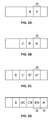
Figs. 2A to 2D shows an array of images printed according to the present invention; and -
Fig. 3 shows a flow chart according to the present invention. -
Fig. 1 shows aprinting press 100 in accordance with the present invention. Theprinting press 100 includes asubstrate supply 10 for providing a substrate to the printing press for printing thereon. The substrate may be apaper web substrate 12 or other suitable printing substrate. Theweb substrate 12 is fed from web supply and infeed 10 through aprinting section 20 of theprinting press 100 then through to any postprint processing stations 40 which may include, for example, a dryer and/or a chill roll stand. Theweb 12 is then passed through aninspection station 50. Aweb rewind unit 60 is located downstream of theinspection station 50. -
Printing section 20 may include a plurality ofprinting units 20. The printing units maybe perfecting or non-perfecting print units. The printing units may be offset print units as shown. Eachprinting unit 20 includes aplate cylinder 26 and ablanket cylinder 24. For perfecting print units, an additional print couple is provided on the lower side of the web. For non-perfecting print units, an impression cylinder may be provided to counteract the blanket cylinder. Each print unit may print a different color, for example, cyan, magenta, yellow or black. - An
inking device 28 is associated with eachplate cylinder 26 as is known in the art. For example, inkingdevice 28 may include an ink train and a dampening train in the case of an offset lithographic printing press as is well known in the art.Ink removal device 30 is associated with theplate cylinder 26 or theblanket cylinder 24. Schematically shownink removal device 30 may, for example provide washing solution or wetting solution to the printing plate, and may include nozzles for applying the solution and a cleaning cloth or roller for removing the ink and washing/wetting solution, and optionally a dryer for drying the plate. An example of such a conventional ink removal device is described inCA 2,154,012 , incorporated herein by reference. Alternatively,ink removal device 30 may be an ink take-away roller 30'(shown in dotted lines) as is known in the art for removing ink from the blanket cylinder or plate cylinder. An example of an ink takeaway roller is described in United States Patent No.5,235,913 , the entire disclosure of which is hereby incorporated by reference. As one of ordinary skill in the art with appreciate, the ink removal device (30, 30') contacts the printing plate of the plate cylinder or the printing blanket of the blanket cylinder to remove ink from the printing plate or printing blanket, and is spaced apart from the plate cylinder or blanket cylinder when the printing unit is printing on the web. - In accordance with the present invention,
printing units 22 ofprint section 20 andpost processing stations 40 are brought online to prepare for printing a first job.Printing units 22 andprocessing stations 40 are brought up to operating speed without runningweb 12. Once these components ofpress 100 are running at operating speed,web 12 is fed fromsupply 10 intoprinting section 20 in a direction A. Thus, the speed of theweb 12 matches the speed of thepress components web 12 at an initial orfirst printing position 34. Images are printed onweb 12, until an image acceptable for inspection is printed; for example, image B shown inFig. 2A . Printing a minimum number of images is desired to reduce the amount of web consumed and amount of ink used. As shown inFig. 2A , two images, image A and image B were printed. Preferably, less than 5 images or impressions are printed. - Once a test image acceptable for inspection is printed,
web 12 is stopped as quickly as possible.Printing units 22 may continue to run while the web is stopped. To accommodate this,printing units 22 may be thrown offweb 12 so as to not interfere with the stoppedweb 12. - Throw-off mechanisms are well known in the art and will not be discussed in detail herein. For example, in a non-perfecting press, moving the impression cylinder out of contact with the blanket cylinder will typically cause the blanket cylinder to come out of contact with the web. Alternatively, the blanket cylinder could be moved upward out of contact with the impression cylinder while the impression cylinder either remains in a fixed position or moves downward. This may or may not require movement of the plate cylinder , ink train, and/or dampening train. For example, depending on the arrangement, blanket cylinder could move in an arcuate upward path while the plate cylinder remains in place. In a perfecting printing unit, the upper blanket cylinder would move upward and/or the lower blanket cylinder would move downward. Depending on the arrangement of the plate cylinder, ink train and dampener train, these components may also move when the printing unit is taken off impression. There are a wide variety of well-known mechanisms that can be used to effect throw off. Non-limiting examples include mounting the plate and/or blanket cylinders in eccentric bearings, mounting the plate and/or blanket cylinders on pivotable brackets, mounting the cylinders on tracks or carriages, and combinations of the foregoing. These mechanisms can be actuated by the
controller 70 with a wide variety of actuators, including motors, hydraulic cylinders, pneumatic cylinders, and the like. - While the web is stopped and the printing units continue to run, ink removal or wetting
devices 30, 30' may also continue to run to keep the plate cylinders and/or blanket cylinders clean and/or from carrying surplus ink. Test image B is inspected whileweb 12 is stopped byinspection unit 50. Theink removal devices 30 or 30' may be moved into contact with the plate cylinder or blanket cylinder to clean the cylinders, and may be moved out of contact with the plate cylinder or blanket cylinder to allow printing. -
Inspection unit 50 may be any type of substrate inspection device, as known in the art. For example,inspection unit 50 may be a visual inspection unit in which a press operator visually inspects the web onsite.Inspection unit 50 may also include cameras and/or a graphic user interface so a press operator may review and inspectweb 12 at a remote location.Inspection unit 50 may be digital.Unit 50 may scanweb 12 and compare theactual web 12 with stored metrics or a known desired result. Many qualities may affect the quality of the printed image including, for example, qualities of the ink, such as the color array, optical density, dot shape, dot gain, ink trapping, doubling, ghosting, evenness of ink distribution, other qualities of the printed image may also include resolution including sharpness and gradation, registration including dot/color registration and printed image registration other qualities may include clarity of the image. Surface characteristics such as gloss, mottling and evenness may also be inspected. Any conceivable or desired characteristic of the web, image, ink, etc. may be reviewed or inspected. - Printing a color control bar in trim areas of the printed image is a desired way to review and achieve color printing and accuracy. On a multicolor press the application of ink in each color may need to be monitored and adjusted individually. Targeted adjustments and controls of individual ink zones and ink fountains may be made based on the color control bar and the printed areas associated with each ink zone and ink fountain.
- If the print quality of image B passes inspection,
web 12 is accelerated to match the press speed including the speed ofprinting units 22.Printing units 22 are moved back into printing position, thrown-on, as known in the art, the ink removal devices 30 (or 30') are disengaged, and the printing press continues printing images onweb 12. Sinceweb 12 was stopped during the inspection of image B,web 12 did not run continuously and superfluously throughpress 100. As a result, the amount ofweb 12 wasted is hereby reduced when compared to conventional methods in whichweb 12 continues to run throughpress 100. - When image B is not acceptable and/or does not pass inspection, another test image suitable for inspection must be printed on
web 12. In order to reduce the amount of web wasted,web substrate 12 is rewound in direction B to afirst printing position 34 where a further image will be printed over the first image A. In accordance with the present invention,web 12 is accelerated up to the matched velocity ofpress 100 andweb 12 will be printed upon by thefirst printing unit 22. A second image A' is printed onweb 12 over the first image A atfirst printing position 34 onweb 12. SeeFig. 2B . A second image B' is printed over the first image B. A third image C is printed on an unprinted area ofweb 12. Image C becomes the first image suitable for inspection during this second round of printing since image C is the only image printed on a clean, unused portion ofweb 12. - In order to rewind and align
web 12 to the proper position for printing by printing unit 22 a plurality of methods may be used. For example,plate cylinder 26 may include anencoder 32 which counts the number of images A, B (SeeFigs. 2A to D ) printed on a given length ofweb 12.Encoder 32 counts two images A, B printed onweb 12.Web 12 is then rewound byweb supply 10 two image/impression lengths. Other methods for aligning a web may also be used. For example, registration marks may be used to rewindweb 12 to thefirst printing position 34 with respect toprinting unit 22. The length of web rewind may also be estimated based on speed set points or speed command values, for example, estimated acceleration of the web and time elapsed. - If image C fails inspection,
web 12 is rewound again to the firstimage printing position 34 so a third image, image A" is printed over image A and image A' as shown inFig. 2C . A third image B" is printed over image B and image B' and a second image C' is printed over image C. The first new image suitable for inspection is image D. If desired,web 12 may be rewound to the secondimage printing position 36 and reprinting may begin over images B, B' instead rewinding the web all the way back to the initial or firstimage printing position 34. See for example,Fig. 2D , in which a third image A is printed over first and second images B, B'. It is not necessary for second or third images to be exactly and precisely aligned with previous images onweb 12. On the contrary, the re-printed web will be discarded so registration of second and third images over first and second images, respectively, does not need to be precise. -
Web 12 may move in either direction, direction A or the oppositedirection B. Controller 70 may moveweb 12 in direction A during a printing operation.Controller 70 may move inweb 12 in the opposite direction B to rewindweb 12 to aprevious printing position Controller 70 in conjunction withencoder 32 may record the number of impressions or images A, B, etc. printed onweb 12 until an acceptable test image B is printed.Controller 70 then controls the rewinding ofweb 12 based on the number of images or impressions printed.Controller 70 may also control the further printing onweb 12 to ensure that a second test image is printed on a clean or unused portion ofweb 12. Thus,controller 70 may record the number of images first printed on the web, control a length of web to be rewound based on the number of first printed images, then control the number of second images printed on the web to ensure at least one second image is printed on a clean or unprinted area ofweb 12. Movement of theink removal devices 30, 30' may also be controlled by thecontroller 70. The throw-off mechanisms discussed above can also be controlled by thecontroller 70. -
Web 12 can be moved in the forward (A) or reverse (B) direction through the press as is known in the art. To move theweb 12 in the forward direction A while the printing units are thrown off the web, thecontroller 70 will instruct one or more driven rollers downstream of the printing units to rotate, thereby pulling the web in the forward direction A through the printing units and towards therewind unit 60. The downstream rollers may, for example, be in a driven nip roller pair in a chill roll stand or be the rewind unit itself, or nip roller pairs in or upstream of the rewind unit. To the move the web in the reverse direction B, while the printing units are thrown off the web, thecontroller 70 will instruct one or more driven rollers upstream of the printing units to rotate in reverse (as compared to the rotation of these rollers during printing) thereby pulling the web in the reverse direction B through the printing units and towards theroll stand 10. The upstream rollers may, for example, be a driven nip roller pair in an infeed. - A
graphic user interface 70 may be employed to interact with a user or press operator. User input may be desired for web and image inspection. The user or press operator may determine if a further test image suitable for inspection needs to be printed. - After image inspection and during web rewind, printing unit inkers and post unit processors may be adjusted based on the results of the inspection and any deviations from the desired results.
- As shown in
Figs. 1 and3 , the printing, inspection and rewind process may be repeated as desired. In accordance with a method of the present invention,printing press 100 is brought up to the desiredpress speed 210,web 12 is then subsequently brought up to pressspeed 220 and images are printed on theweb 230. Once a test image is printed, the web is stopped 240 and the image and/or web are inspected 250. If needed,web 12 is rewound 260 to an initial orprevious printing position Web 12 is brought up to press speed again 270 and further printing begins 280. Successive images printed onweb 12 are printed over previously printed portions ofweb 12, with new test images to be inspected being printed on clean portions ofweb 12. If test images pass inspection,web 12 is not rewound.Web 12 is brought up to pressspeed 270 and printing continues 280. The web stopping, rewind, and printing loop may be repeated as many times as desired until an acceptable or desired image is printed. - By rewinding the web to an initial or previous printing position, multiple images and process adjustments consume only a minimal amount of substrate web. No additional substrate is consumed during the inspection process since the web is stopped during inspection. Inspection can verify all processes not limited to correct image, ink coverage, web coating, image numbering, digital imaging, etc.
- It should be noted that the manner in which a controller, such as
controller 70 can be configured to controlprinting units 22 to throw-off the web, controlink removal devices 30, 30' and to move the web in the forward direction A and the reverses direction B is well known in the art, and therefore will not be recounted herein. Rather, the embodiments of the present invention are directed to a novel system for reaching a saleable copy during make-ready or startup with reduced waste. In this regard,controller 70 can, for example, be one or more programmable logic controller(s) (PLC), or any suitable hardware based or software based electronic controller or controllers including, for example, one or more microcomputers with related support circuitry, one or more finite static machine(s), one or more field programmable gate array(s), FPGA, or one or more application-specific integrated circuit(s), ASIC, among others. - Although
Figures 1-7 illustrate the present invention in the context of a web offset lithographic press, it should be appreciated that the present invention can be applied to any type of web press including without limitation flexographic presses, gravure presses, digital presses, and inkjet presses. Further, the presses may include a single printing unit or a plurality of printing units. Moreover, it should be understood that the web itself could be any continuous substrate to be printed, included without limitation, paper, plastic, cardboard, corrugated cardboard, and the like. - In the preceding specification, the invention has been described with reference to specific exemplary embodiments and examples thereof. It will, however, be evident that various modifications and changes may be made thereto without departing from the broader spirit and scope of invention as set forth in the claims that follow. The specification and drawings are accordingly to be regarded in an illustrative manner rather than a restrictive sense.
- The invention comprises generally the following features, in every possible combination.
- A printing press comprising:
- a web supply supplying a web to the press;
- at least one printing unit configured and arranged to print images on the web;
- an inspection unit configured and arranged to inspect the images on the web;
- a rewind device configured and arranged tor rewind the web to one of the printing positions;
- a controller, the controller coupled to at least one printing unit and the rewind device, the controller configured and arranged to control the at least one printing unit to print first images on the web at corresponding printing position, and, after the inspection unit inspects the images on the web, control the rewind device to rewind the web to one of the printing positions, and thereafter, control the at least one printing unit to print at least one further image over at least one of the first images on the web.
- The at least one printing unit is a plurality of printing units.
- The printing position is a position of the web with respect to one of the printing units.
- The controller is configured to record or determine a number of first images that are printed on the web and control an amount of web to rewind based on the number of first images printed on the web.
- The controller further controls printing the at least one further images so at least one of the further images is printed on an unprinted area of the web.
- Each printing unit includes:
- a plate cylinder and a blanket cylinder,
- an ink removal device configured and arranged to selectively contact one of the plate cylinder and the blanket cylinder, and
- a throw off mechanism configured and arranged to selectively separate the blanket cylinder from the web; and
- One of the plate cylinder and the blanket cylinder is the blanket cylinder;
wherein the blanket cylinder includes a printing blanket; and
wherein the ink removal device includes a roller, and wherein the ink removal device is configured and arranged to selectively move the roller into rolling contact with the printing blanket of the blanket cylinder. - One of the plate cylinder and the blanket cylinder is the plate cylinder;
wherein the plate cylinder includes a printing plate; and
wherein the ink removal device is configured and arranged to selectively contact the printing plate of the plate cylinder. - A method for printing an image comprising the steps of:
- supplying a web to a printing press, in particular the printing press being a printing press according to one of the preceding claims;
- printing a plurality of first images on the web at corresponding printing positions;
- inspecting one of the first images on the web;
- rewinding the web to one of the printing positions; and
- printing a further image over one of the first images on the web.
- The printing press includes a printing unit having a plate cylinder and a blanket cylinder, the method further comprising:
- after the step of printing the plurality of first images and before the step of rewinding the web:
- separating the blanket cylinder from the web using a throw off mechanism,
- moving an ink removal device into contact with one of the plate cylinder or blanket cylinder, and
- removing ink from said one of the plate cylinder or the blanket cylinder with the ink removal device; and
- after the step of rewinding and before the step of printing the further image:
- moving the ink removal device out of contact with said one of the plate cylinder or blanket cylinder, and
- bringing the blanket cylinder into contact with the web using the throw off mechanism.
- A method for printing an image comprising the steps of:
- moving a web in a first direction;
- printing a first image on the web moving in the first direction;
- rewinding the web;
- moving the web in the first direction; and
- printing a further image on the web moving in the first direction. (Priority Claim 15)
- The steps of printing the first image and printing the further image are performed by a printing unit including a plate cylinder an a blanket cylinder, and wherein the method further comprises:
- after the step of printing the first image and before the step of rewinding the web:
- separating the blanket cylinder from the web using a throw off mechanism,
- moving an ink removal device into contact with one of the plate cylinder or blanket cylinder, and removing ink from said one of the plate cylinder or the blanket cylinder with the ink removal device; and
- after the step of rewinding and before the step of printing the further image:
- moving the ink removal device out of contact with said one of the plate cylinder or
- blanket cylinder, and
- bringing the blanket cylinder into contact with the web using the throw off mechanism.
- After the step of inspecting and before the step of printing the further image,
adjusting individual ink zones in the printing unit. - Wherein said one of the plate cylinder and the blanket cylinder is the blanket cylinder, the blanket cylinder including a printing blanket, and wherein the step of moving includes:
- moving a roller in the ink removal device into rolling contact with the printing blanket of the blanket cylinder to remove ink from the printing blanket.
- Said one of the plate cylinder and the blanket cylinder is the plate cylinder, the plate cylinder including a printing plate, and wherein the step of moving includes:
- moving the ink removal device into contact with the printing plate of the plate cylinder to remove ink from the printing plate. (Priority Claims 14 and 20)
- The methods further comprise the step of making adjustments to the printed image or printing press after the first image is printed on the web.
Claims (16)
- A printing press comprising:a web supply supplying a web to the press;at least one printing unit configured and arranged to print images on the web;an inspection unit configured and arranged to inspect the images on the web;a rewind device configured and arranged tor rewind the web to one of the printing positions;a controller, the controller coupled to at least one printing unit and the rewind device, the controller configured and arranged to control the at least one printing unit to print first images on the web at corresponding printing position, and, after the inspection unit inspects the images on the web, control the rewind device to rewind the web to one of the printing positions, and thereafter, control the at least one printing unit to print at least one further image over at least one of the first images on the web.
- The printing press as recited in claim 1 wherein the at least one printing unit is a plurality of printing units.
- The printing press as recited in claim 2 wherein the printing position is a position of the web with respect to one of the printing units.
- The printing press as recited in any one of claims 1 to 3 wherein the controller is configured to record or determine a number of first images that are printed on the web and control an amount of web to rewind based on the number of first images printed on the web.
- The printing press as recited in claim 3 or 4 wherein the controller further controls printing the at least one further images so at least one of the further images is printed on an unprinted area of the web.
- The printing press according to at least claim 2,
wherein each printing unit includes:a plate cylinder and a blanket cylinder,an ink removal device configured and arranged to selectively contact one of the plate cylinder and the blanket cylinder, anda throw off mechanism configured and arranged to selectively separate the blanket cylinder from the web; andwherein the controller is configured and arranged to control the throw off mechanism to separate the blanket cylinder from the web, and while the blanket cylinder is separated from the web, control the ink removal device to contact one of the plate cylinder and the blanket cylinder. - The printing press of claim 6,
wherein said one of the plate cylinder and the blanket cylinder is the blanket cylinder; wherein the blanket cylinder includes a printing blanket; and
wherein the ink removal device includes a roller, and wherein the ink removal device is configured and arranged to selectively move the roller into rolling contact with the printing blanket of the blanket cylinder. - The printing press of claim 6,
wherein said one of the plate cylinder and the blanket cylinder is the plate cylinder;
wherein the plate cylinder includes a printing plate; and
wherein the ink removal device is configured and arranged to selectively contact the printing plate of the plate cylinder. - A method for printing an image comprising the steps of:supplying a web to a printing press, in particular the printing press being a printing press according to one of the preceding claims;printing a plurality of first images on the web at corresponding printing positions;inspecting one of the first images on the web;rewinding the web to one of the printing positions; andprinting a further image over one of the first images on the web.
- The method of claim 9, wherein the printing press includes a printing unit having a plate cylinder and a blanket cylinder, the method further comprising:after the step of printing the plurality of first images and before the step of rewinding the web:separating the blanket cylinder from the web using a throw off mechanism,moving an ink removal device into contact with one of the plate cylinder or blanket cylinder, andremoving ink from said one of the plate cylinder or the blanket cylinder with the ink removal device; andafter the step of rewinding and before the step of printing the further image:moving the ink removal device out of contact with said one of the plate cylinder or blanket cylinder, andbringing the blanket cylinder into contact with the web using the throw off mechanism. (Priority Claim 11)
- A method for printing an image comprising the steps of:moving a web in a first direction;printing a first image on the web moving in the first direction;rewinding the web;moving the web in the first direction; andprinting a further image on the web moving in the first direction. (Priority Claim 15)
- The method of claim 11, wherein the steps of printing the first image and printing the further image are performed by a printing unit including a plate cylinder an a blanket cylinder, and wherein the method further comprises:after the step of printing the first image and before the step of rewinding the web:separating the blanket cylinder from the web using a throw off mechanism,moving an ink removal device into contact with one of the plate cylinder or blanket cylinder, and removing ink from said one of the plate cylinder or the blanket cylinder with the ink removal device; andafter the step of rewinding and before the step of printing the further image:moving the ink removal device out of contact with said one of the plate cylinder orblanket cylinder, andbringing the blanket cylinder into contact with the web using the throw off mechanism. (Priority Claim 17)
- The method of claim 10 or 12, further comprising,
after the step of inspecting and before the step of printing the further image,
adjusting individual ink zones in the printing unit. (Priority Claims 12 and 18) - The method of any one of claims 10, 12 or 13, wherein said one of the plate cylinder and the blanket cylinder is the blanket cylinder, the blanket cylinder including a printing blanket, and wherein the step of moving includes:moving a roller in the ink removal device into rolling contact with the printing blanket of the blanket cylinder to remove ink from the printing blanket. (Priority Claims 13 and 19)
- The method of any one of claims 10, 12, 13 or 14, wherein said one of the plate cylinder and the blanket cylinder is the plate cylinder, the plate cylinder including a printing plate, and wherein the step of moving includes:moving the ink removal device into contact with the printing plate of the plate cylinder to remove ink from the printing plate. (Priority Claims 14 and 20)
- The method as recited in any one of claims 9 to 15, further comprising making adjustments to the printed image or printing press after the first image is printed on the web. (Priority Claims 10 and 16)
Applications Claiming Priority (2)
| Application Number | Priority Date | Filing Date | Title |
|---|---|---|---|
| US201261747774P | 2012-12-31 | 2012-12-31 | |
| US14/136,210 US9492996B2 (en) | 2012-12-31 | 2013-12-20 | Web control to reduce waste and method |
Publications (2)
| Publication Number | Publication Date |
|---|---|
| EP2749414A1 true EP2749414A1 (en) | 2014-07-02 |
| EP2749414B1 EP2749414B1 (en) | 2017-04-26 |
Family
ID=49918479
Family Applications (1)
| Application Number | Title | Priority Date | Filing Date |
|---|---|---|---|
| EP13199739.7A Active EP2749414B1 (en) | 2012-12-31 | 2013-12-30 | Web control to reduce waste and corresponding method |
Country Status (3)
| Country | Link |
|---|---|
| US (1) | US9492996B2 (en) |
| EP (1) | EP2749414B1 (en) |
| CN (1) | CN103909727B (en) |
Cited By (4)
| Publication number | Priority date | Publication date | Assignee | Title |
|---|---|---|---|---|
| EP2886344A1 (en) * | 2013-12-19 | 2015-06-24 | Goss International Americas, Inc. | Method for reducing web printing press start-up waste, and related printing press and printed product |
| DE202015101699U1 (en) * | 2015-04-07 | 2016-07-08 | Bobst Bielefeld Gmbh | Rotary press |
| EP3078495A1 (en) * | 2015-04-07 | 2016-10-12 | Bobst Bielefeld GmbH | Rotary printing press |
| WO2016173606A1 (en) * | 2015-04-30 | 2016-11-03 | Hewlett-Packard Indigo B.V. | Printed output inspection |
Families Citing this family (10)
| Publication number | Priority date | Publication date | Assignee | Title |
|---|---|---|---|---|
| DE202012102681U1 (en) * | 2012-07-18 | 2012-08-14 | Druckhaus Schütze GmbH | Web offset printing machine for single-sided printing of a material web |
| US9616657B2 (en) * | 2013-10-01 | 2017-04-11 | Goss International Americas, Inc. | Closed loop ink thickness control system with reduced substrate waste in a printing press |
| JP6493192B2 (en) * | 2015-12-15 | 2019-04-03 | コニカミノルタ株式会社 | Image forming apparatus |
| CN109963716B (en) * | 2016-10-18 | 2020-12-11 | 旭化成株式会社 | Printing device |
| WO2018082974A1 (en) * | 2016-11-01 | 2018-05-11 | OCE Holding B.V. | Printing system and method for printing an image on a printed media piece without using registration marks |
| US11449290B2 (en) | 2017-07-14 | 2022-09-20 | Georgia-Pacific Corrugated Llc | Control plan for paper, sheet, and box manufacturing systems |
| US20190016551A1 (en) * | 2017-07-14 | 2019-01-17 | Georgia-Pacific Corrugated, LLC | Reel editor for pre-print paper, sheet, and box manufacturing systems |
| US11520544B2 (en) | 2017-07-14 | 2022-12-06 | Georgia-Pacific Corrugated Llc | Waste determination for generating control plans for digital pre-print paper, sheet, and box manufacturing systems |
| US10642551B2 (en) | 2017-07-14 | 2020-05-05 | Georgia-Pacific Corrugated Llc | Engine for generating control plans for digital pre-print paper, sheet, and box manufacturing systems |
| US11485101B2 (en) | 2017-07-14 | 2022-11-01 | Georgia-Pacific Corrugated Llc | Controls for paper, sheet, and box manufacturing systems |
Citations (2)
| Publication number | Priority date | Publication date | Assignee | Title |
|---|---|---|---|---|
| GB1557652A (en) * | 1977-03-17 | 1979-12-12 | Baker Perkins Holdings Ltd | Web fed multi unit rotary printing presses and to methods operating the same |
| CA2154012A1 (en) * | 1994-07-22 | 1996-01-23 | Barbara Nussel | An erasable printing plate and a process and apparatus for erasing and regenerating the printing plate |
Family Cites Families (15)
| Publication number | Priority date | Publication date | Assignee | Title |
|---|---|---|---|---|
| DE2353359C3 (en) * | 1973-10-24 | 1979-05-10 | Windmoeller & Hoelscher, 4540 Lengerich | Method for avoiding waste when a multicolor RoUen rotary printing press is shut down for the removal of samples from the web during transfer printing |
| IT1071327B (en) * | 1976-08-25 | 1985-04-02 | Buettner Schilde Haas Ag | DEVICE FOR DRYING TAPE-MATERIAL, PERMEABLE TO AIR |
| US5412577A (en) * | 1992-10-28 | 1995-05-02 | Quad/Tech International | Color registration system for a printing press |
| US5816161A (en) * | 1994-07-22 | 1998-10-06 | Man Roland Druckmaschinen Ag | Erasable printing plate having a smooth pore free metallic surface |
| US6053107A (en) | 1999-01-13 | 2000-04-25 | Paper Converting Machine Co. | Method and apparatus for registering a pre-printed web on a printing press |
| GB9909228D0 (en) | 1999-04-23 | 1999-06-16 | Holmdale Precision Ltd | A roll rewinding apparatus |
| US6796240B2 (en) * | 2001-06-04 | 2004-09-28 | Quad/Tech, Inc. | Printing press register control using colorpatch targets |
| US20040169888A1 (en) * | 2003-02-28 | 2004-09-02 | Eveland Michael J. | Method and apparatus for printing on a partially-printed medium |
| DE10319770A1 (en) * | 2003-05-02 | 2004-12-09 | Koenig & Bauer Ag | Method for regulating the color density of a color applied by a printing press to a printing medium and device for regulating various parameters relevant for the printing process of a printing press |
| EP1743771A1 (en) * | 2005-07-14 | 2007-01-17 | Oxy-Dry Maschinen GmbH | Device for cleaning cylinders of a printing machine |
| US8042910B2 (en) | 2008-05-29 | 2011-10-25 | Hewlett-Packard Development Company, L.P. | Replaceable printbar assembly |
| US8240843B2 (en) | 2009-03-16 | 2012-08-14 | Hewlett-Packard Development Company, L.P. | Media roll winder for digital web press |
| US20110006148A1 (en) | 2009-07-13 | 2011-01-13 | Primera Technology, Inc. | Tensioner for continuous web rewind roll |
| US20110168042A1 (en) | 2010-01-11 | 2011-07-14 | Goss International Americas, Inc. | Variable Oscillating Web Printing Press and Method |
| US20110297023A1 (en) | 2010-06-04 | 2011-12-08 | Goss International Americas, Inc. | Apparatus and method for producing newspapers from a printed web |
-
2013
- 2013-12-20 US US14/136,210 patent/US9492996B2/en active Active
- 2013-12-30 EP EP13199739.7A patent/EP2749414B1/en active Active
- 2013-12-31 CN CN201310757334.9A patent/CN103909727B/en active Active
Patent Citations (2)
| Publication number | Priority date | Publication date | Assignee | Title |
|---|---|---|---|---|
| GB1557652A (en) * | 1977-03-17 | 1979-12-12 | Baker Perkins Holdings Ltd | Web fed multi unit rotary printing presses and to methods operating the same |
| CA2154012A1 (en) * | 1994-07-22 | 1996-01-23 | Barbara Nussel | An erasable printing plate and a process and apparatus for erasing and regenerating the printing plate |
Cited By (10)
| Publication number | Priority date | Publication date | Assignee | Title |
|---|---|---|---|---|
| EP2886344A1 (en) * | 2013-12-19 | 2015-06-24 | Goss International Americas, Inc. | Method for reducing web printing press start-up waste, and related printing press and printed product |
| US9616655B2 (en) | 2013-12-19 | 2017-04-11 | Goss International Americas, Inc. | Method for reducing web printing press start-up waste, and related printing press and printed product |
| US9873243B2 (en) | 2013-12-19 | 2018-01-23 | Goss International Americas, Inc. | Method for reducing web printing press start-up waste, and related printing press and printed product |
| DE202015101699U1 (en) * | 2015-04-07 | 2016-07-08 | Bobst Bielefeld Gmbh | Rotary press |
| EP3078495A1 (en) * | 2015-04-07 | 2016-10-12 | Bobst Bielefeld GmbH | Rotary printing press |
| EP3078496A1 (en) * | 2015-04-07 | 2016-10-12 | Bobst Bielefeld GmbH | Rotary printing press |
| WO2016173606A1 (en) * | 2015-04-30 | 2016-11-03 | Hewlett-Packard Indigo B.V. | Printed output inspection |
| CN107405912A (en) * | 2015-04-30 | 2017-11-28 | 惠普印迪格公司 | Printout checks |
| CN107405912B (en) * | 2015-04-30 | 2019-08-06 | 惠普印迪格公司 | Printout checks |
| US10603895B2 (en) | 2015-04-30 | 2020-03-31 | Hp Indigo B.V. | Printed output inspection |
Also Published As
| Publication number | Publication date |
|---|---|
| CN103909727A (en) | 2014-07-09 |
| US9492996B2 (en) | 2016-11-15 |
| CN103909727B (en) | 2017-12-05 |
| EP2749414B1 (en) | 2017-04-26 |
| US20140182470A1 (en) | 2014-07-03 |
Similar Documents
| Publication | Publication Date | Title |
|---|---|---|
| EP2749414B1 (en) | Web control to reduce waste and corresponding method | |
| US9004635B2 (en) | Method to execute a pause function during the print operation in an inkjet printing | |
| RU2647231C2 (en) | Gravure printing press, and printing system having a gravure printing press | |
| JP2010532724A (en) | Removing printing ink | |
| US9242454B2 (en) | Independent inker control and method | |
| JP2004313829A (en) | Varnish application method, varnish application apparatus and printer | |
| US10919289B2 (en) | Printing machine with a twin printing unit and method for operating such a printing machine | |
| US9027475B2 (en) | Method for changing edition on a rotary press | |
| US9789680B2 (en) | Method for adjusting the print repeat length of a print image in a multicolor rotary printing machine | |
| JP6652328B2 (en) | Composite printing machine having gravure printing device and composite printing method for performing gravure printing as additional printing | |
| US6705219B2 (en) | Rotary offset printing unit with rubber blanket belt and offset printing method | |
| DE102016214713B4 (en) | Method for checking a strip width of a press strip | |
| JP2014516823A (en) | Rotary offset printing machine and method for printing on a substrate | |
| US20050241505A1 (en) | Printing press and method for printing two webs | |
| US9616655B2 (en) | Method for reducing web printing press start-up waste, and related printing press and printed product | |
| US6837161B2 (en) | Ink removal method for printing press | |
| RU58444U1 (en) | FLEXOGRAPHIC DEVICE FOR PRINTING ON A POLYMER TAPE | |
| JP2007118543A (en) | Printing machine and method for operating printing machine | |
| US20180361767A1 (en) | Rotogravure unit including a pull roller and narrow-web rotary printing machine | |
| JP2011521807A (en) | Operation of non-heated film unit with printing device | |
| JP2010201650A (en) | Printing machine and method for operating printing machine | |
| JP2009233983A (en) | Printing machine and its control method | |
| JP2004155183A (en) | Lithographic printing machine | |
| JP2006053550A (en) | Method of tandem offset color printing | |
| JP2009220361A (en) | Dampening device for printer, and printer |
Legal Events
| Date | Code | Title | Description |
|---|---|---|---|
| 17P | Request for examination filed |
Effective date: 20131230 |
|
| AK | Designated contracting states |
Kind code of ref document: A1 Designated state(s): AL AT BE BG CH CY CZ DE DK EE ES FI FR GB GR HR HU IE IS IT LI LT LU LV MC MK MT NL NO PL PT RO RS SE SI SK SM TR |
|
| AX | Request for extension of the european patent |
Extension state: BA ME |
|
| PUAI | Public reference made under article 153(3) epc to a published international application that has entered the european phase |
Free format text: ORIGINAL CODE: 0009012 |
|
| R17P | Request for examination filed (corrected) |
Effective date: 20141223 |
|
| RBV | Designated contracting states (corrected) |
Designated state(s): AL AT BE BG CH CY CZ DE DK EE ES FI FR GB GR HR HU IE IS IT LI LT LU LV MC MK MT NL NO PL PT RO RS SE SI SK SM TR |
|
| GRAP | Despatch of communication of intention to grant a patent |
Free format text: ORIGINAL CODE: EPIDOSNIGR1 |
|
| RIC1 | Information provided on ipc code assigned before grant |
Ipc: B41F 33/00 20060101ALI20161206BHEP Ipc: B41F 33/06 20060101ALI20161206BHEP Ipc: B41F 13/24 20060101ALI20161206BHEP Ipc: B41F 13/04 20060101AFI20161206BHEP Ipc: B65H 23/00 20060101ALI20161206BHEP |
|
| INTG | Intention to grant announced |
Effective date: 20170105 |
|
| GRAS | Grant fee paid |
Free format text: ORIGINAL CODE: EPIDOSNIGR3 |
|
| GRAJ | Information related to disapproval of communication of intention to grant by the applicant or resumption of examination proceedings by the epo deleted |
Free format text: ORIGINAL CODE: EPIDOSDIGR1 |
|
| GRAL | Information related to payment of fee for publishing/printing deleted |
Free format text: ORIGINAL CODE: EPIDOSDIGR3 |
|
| GRAR | Information related to intention to grant a patent recorded |
Free format text: ORIGINAL CODE: EPIDOSNIGR71 |
|
| GRAA | (expected) grant |
Free format text: ORIGINAL CODE: 0009210 |
|
| INTC | Intention to grant announced (deleted) | ||
| AK | Designated contracting states |
Kind code of ref document: B1 Designated state(s): AL AT BE BG CH CY CZ DE DK EE ES FI FR GB GR HR HU IE IS IT LI LT LU LV MC MK MT NL NO PL PT RO RS SE SI SK SM TR |
|
| INTG | Intention to grant announced |
Effective date: 20170321 |
|
| REG | Reference to a national code |
Ref country code: GB Ref legal event code: FG4D |
|
| REG | Reference to a national code |
Ref country code: CH Ref legal event code: EP Ref country code: CH Ref legal event code: NV Representative=s name: ARNOLD AND SIEDSMA AG, CH |
|
| REG | Reference to a national code |
Ref country code: AT Ref legal event code: REF Ref document number: 887512 Country of ref document: AT Kind code of ref document: T Effective date: 20170515 |
|
| REG | Reference to a national code |
Ref country code: IE Ref legal event code: FG4D |
|
| REG | Reference to a national code |
Ref country code: DE Ref legal event code: R096 Ref document number: 602013020270 Country of ref document: DE |
|
| REG | Reference to a national code |
Ref country code: NL Ref legal event code: MP Effective date: 20170426 |
|
| REG | Reference to a national code |
Ref country code: LT Ref legal event code: MG4D |
|
| REG | Reference to a national code |
Ref country code: AT Ref legal event code: MK05 Ref document number: 887512 Country of ref document: AT Kind code of ref document: T Effective date: 20170426 |
|
| PG25 | Lapsed in a contracting state [announced via postgrant information from national office to epo] |
Ref country code: NL Free format text: LAPSE BECAUSE OF FAILURE TO SUBMIT A TRANSLATION OF THE DESCRIPTION OR TO PAY THE FEE WITHIN THE PRESCRIBED TIME-LIMIT Effective date: 20170426 |
|
| PG25 | Lapsed in a contracting state [announced via postgrant information from national office to epo] |
Ref country code: HR Free format text: LAPSE BECAUSE OF FAILURE TO SUBMIT A TRANSLATION OF THE DESCRIPTION OR TO PAY THE FEE WITHIN THE PRESCRIBED TIME-LIMIT Effective date: 20170426 Ref country code: NO Free format text: LAPSE BECAUSE OF FAILURE TO SUBMIT A TRANSLATION OF THE DESCRIPTION OR TO PAY THE FEE WITHIN THE PRESCRIBED TIME-LIMIT Effective date: 20170726 Ref country code: LT Free format text: LAPSE BECAUSE OF FAILURE TO SUBMIT A TRANSLATION OF THE DESCRIPTION OR TO PAY THE FEE WITHIN THE PRESCRIBED TIME-LIMIT Effective date: 20170426 Ref country code: GR Free format text: LAPSE BECAUSE OF FAILURE TO SUBMIT A TRANSLATION OF THE DESCRIPTION OR TO PAY THE FEE WITHIN THE PRESCRIBED TIME-LIMIT Effective date: 20170727 Ref country code: AT Free format text: LAPSE BECAUSE OF FAILURE TO SUBMIT A TRANSLATION OF THE DESCRIPTION OR TO PAY THE FEE WITHIN THE PRESCRIBED TIME-LIMIT Effective date: 20170426 Ref country code: ES Free format text: LAPSE BECAUSE OF FAILURE TO SUBMIT A TRANSLATION OF THE DESCRIPTION OR TO PAY THE FEE WITHIN THE PRESCRIBED TIME-LIMIT Effective date: 20170426 Ref country code: FI Free format text: LAPSE BECAUSE OF FAILURE TO SUBMIT A TRANSLATION OF THE DESCRIPTION OR TO PAY THE FEE WITHIN THE PRESCRIBED TIME-LIMIT Effective date: 20170426 |
|
| PG25 | Lapsed in a contracting state [announced via postgrant information from national office to epo] |
Ref country code: RS Free format text: LAPSE BECAUSE OF FAILURE TO SUBMIT A TRANSLATION OF THE DESCRIPTION OR TO PAY THE FEE WITHIN THE PRESCRIBED TIME-LIMIT Effective date: 20170426 Ref country code: LV Free format text: LAPSE BECAUSE OF FAILURE TO SUBMIT A TRANSLATION OF THE DESCRIPTION OR TO PAY THE FEE WITHIN THE PRESCRIBED TIME-LIMIT Effective date: 20170426 Ref country code: SE Free format text: LAPSE BECAUSE OF FAILURE TO SUBMIT A TRANSLATION OF THE DESCRIPTION OR TO PAY THE FEE WITHIN THE PRESCRIBED TIME-LIMIT Effective date: 20170426 Ref country code: IS Free format text: LAPSE BECAUSE OF FAILURE TO SUBMIT A TRANSLATION OF THE DESCRIPTION OR TO PAY THE FEE WITHIN THE PRESCRIBED TIME-LIMIT Effective date: 20170826 Ref country code: BG Free format text: LAPSE BECAUSE OF FAILURE TO SUBMIT A TRANSLATION OF THE DESCRIPTION OR TO PAY THE FEE WITHIN THE PRESCRIBED TIME-LIMIT Effective date: 20170726 Ref country code: PL Free format text: LAPSE BECAUSE OF FAILURE TO SUBMIT A TRANSLATION OF THE DESCRIPTION OR TO PAY THE FEE WITHIN THE PRESCRIBED TIME-LIMIT Effective date: 20170426 |
|
| REG | Reference to a national code |
Ref country code: DE Ref legal event code: R097 Ref document number: 602013020270 Country of ref document: DE |
|
| PG25 | Lapsed in a contracting state [announced via postgrant information from national office to epo] |
Ref country code: DK Free format text: LAPSE BECAUSE OF FAILURE TO SUBMIT A TRANSLATION OF THE DESCRIPTION OR TO PAY THE FEE WITHIN THE PRESCRIBED TIME-LIMIT Effective date: 20170426 Ref country code: CZ Free format text: LAPSE BECAUSE OF FAILURE TO SUBMIT A TRANSLATION OF THE DESCRIPTION OR TO PAY THE FEE WITHIN THE PRESCRIBED TIME-LIMIT Effective date: 20170426 Ref country code: EE Free format text: LAPSE BECAUSE OF FAILURE TO SUBMIT A TRANSLATION OF THE DESCRIPTION OR TO PAY THE FEE WITHIN THE PRESCRIBED TIME-LIMIT Effective date: 20170426 Ref country code: RO Free format text: LAPSE BECAUSE OF FAILURE TO SUBMIT A TRANSLATION OF THE DESCRIPTION OR TO PAY THE FEE WITHIN THE PRESCRIBED TIME-LIMIT Effective date: 20170426 Ref country code: SK Free format text: LAPSE BECAUSE OF FAILURE TO SUBMIT A TRANSLATION OF THE DESCRIPTION OR TO PAY THE FEE WITHIN THE PRESCRIBED TIME-LIMIT Effective date: 20170426 |
|
| PG25 | Lapsed in a contracting state [announced via postgrant information from national office to epo] |
Ref country code: IT Free format text: LAPSE BECAUSE OF FAILURE TO SUBMIT A TRANSLATION OF THE DESCRIPTION OR TO PAY THE FEE WITHIN THE PRESCRIBED TIME-LIMIT Effective date: 20170426 Ref country code: SM Free format text: LAPSE BECAUSE OF FAILURE TO SUBMIT A TRANSLATION OF THE DESCRIPTION OR TO PAY THE FEE WITHIN THE PRESCRIBED TIME-LIMIT Effective date: 20170426 |
|
| PLBE | No opposition filed within time limit |
Free format text: ORIGINAL CODE: 0009261 |
|
| STAA | Information on the status of an ep patent application or granted ep patent |
Free format text: STATUS: NO OPPOSITION FILED WITHIN TIME LIMIT |
|
| 26N | No opposition filed |
Effective date: 20180129 |
|
| PG25 | Lapsed in a contracting state [announced via postgrant information from national office to epo] |
Ref country code: SI Free format text: LAPSE BECAUSE OF FAILURE TO SUBMIT A TRANSLATION OF THE DESCRIPTION OR TO PAY THE FEE WITHIN THE PRESCRIBED TIME-LIMIT Effective date: 20170426 |
|
| REG | Reference to a national code |
Ref country code: DE Ref legal event code: R119 Ref document number: 602013020270 Country of ref document: DE |
|
| REG | Reference to a national code |
Ref country code: CH Ref legal event code: PL |
|
| GBPC | Gb: european patent ceased through non-payment of renewal fee |
Effective date: 20171230 |
|
| PG25 | Lapsed in a contracting state [announced via postgrant information from national office to epo] |
Ref country code: MT Free format text: LAPSE BECAUSE OF NON-PAYMENT OF DUE FEES Effective date: 20171230 Ref country code: LU Free format text: LAPSE BECAUSE OF NON-PAYMENT OF DUE FEES Effective date: 20171230 |
|
| REG | Reference to a national code |
Ref country code: FR Ref legal event code: ST Effective date: 20180831 |
|
| REG | Reference to a national code |
Ref country code: IE Ref legal event code: MM4A |
|
| REG | Reference to a national code |
Ref country code: BE Ref legal event code: MM Effective date: 20171231 |
|
| PG25 | Lapsed in a contracting state [announced via postgrant information from national office to epo] |
Ref country code: IE Free format text: LAPSE BECAUSE OF NON-PAYMENT OF DUE FEES Effective date: 20171230 Ref country code: FR Free format text: LAPSE BECAUSE OF NON-PAYMENT OF DUE FEES Effective date: 20180102 Ref country code: DE Free format text: LAPSE BECAUSE OF NON-PAYMENT OF DUE FEES Effective date: 20180703 |
|
| REG | Reference to a national code |
Ref country code: DE Ref legal event code: R073 Ref document number: 602013020270 Country of ref document: DE |
|
| PG25 | Lapsed in a contracting state [announced via postgrant information from national office to epo] |
Ref country code: GB Free format text: LAPSE BECAUSE OF NON-PAYMENT OF DUE FEES Effective date: 20171230 Ref country code: LI Free format text: LAPSE BECAUSE OF NON-PAYMENT OF DUE FEES Effective date: 20171231 Ref country code: BE Free format text: LAPSE BECAUSE OF NON-PAYMENT OF DUE FEES Effective date: 20171231 Ref country code: CH Free format text: LAPSE BECAUSE OF NON-PAYMENT OF DUE FEES Effective date: 20171231 |
|
| REG | Reference to a national code |
Ref country code: CH Ref legal event code: AECN Free format text: DAS PATENT IST AUFGRUND DES WEITERBEHANDLUNGSANTRAGS VOM 05.10.2018 REAKTIVIERT WORDEN. Ref country code: CH Ref legal event code: NV Representative=s name: MICHELI AND CIE SA, CH |
|
| REG | Reference to a national code |
Ref country code: DE Ref legal event code: R074 Ref document number: 602013020270 Country of ref document: DE |
|
| REG | Reference to a national code |
Ref country code: DE Ref legal event code: R074 Ref document number: 602013020270 Country of ref document: DE |
|
| PG25 | Lapsed in a contracting state [announced via postgrant information from national office to epo] |
Ref country code: CH Free format text: LAPSE BECAUSE OF NON-PAYMENT OF DUE FEES Effective date: 20171231 Ref country code: LI Free format text: LAPSE BECAUSE OF NON-PAYMENT OF DUE FEES Effective date: 20171231 |
|
| PGRI | Patent reinstated in contracting state [announced from national office to epo] |
Ref country code: CH Effective date: 20181205 Ref country code: LI Effective date: 20181205 |
|
| PG25 | Lapsed in a contracting state [announced via postgrant information from national office to epo] |
Ref country code: DE Free format text: LAPSE BECAUSE OF NON-PAYMENT OF DUE FEES Effective date: 20180703 |
|
| PGRI | Patent reinstated in contracting state [announced from national office to epo] |
Ref country code: DE Effective date: 20190213 |
|
| PG25 | Lapsed in a contracting state [announced via postgrant information from national office to epo] |
Ref country code: MC Free format text: LAPSE BECAUSE OF FAILURE TO SUBMIT A TRANSLATION OF THE DESCRIPTION OR TO PAY THE FEE WITHIN THE PRESCRIBED TIME-LIMIT Effective date: 20170426 Ref country code: HU Free format text: LAPSE BECAUSE OF FAILURE TO SUBMIT A TRANSLATION OF THE DESCRIPTION OR TO PAY THE FEE WITHIN THE PRESCRIBED TIME-LIMIT; INVALID AB INITIO Effective date: 20131230 |
|
| PG25 | Lapsed in a contracting state [announced via postgrant information from national office to epo] |
Ref country code: CY Free format text: LAPSE BECAUSE OF NON-PAYMENT OF DUE FEES Effective date: 20170426 |
|
| PG25 | Lapsed in a contracting state [announced via postgrant information from national office to epo] |
Ref country code: MK Free format text: LAPSE BECAUSE OF FAILURE TO SUBMIT A TRANSLATION OF THE DESCRIPTION OR TO PAY THE FEE WITHIN THE PRESCRIBED TIME-LIMIT Effective date: 20170426 |
|
| PG25 | Lapsed in a contracting state [announced via postgrant information from national office to epo] |
Ref country code: TR Free format text: LAPSE BECAUSE OF FAILURE TO SUBMIT A TRANSLATION OF THE DESCRIPTION OR TO PAY THE FEE WITHIN THE PRESCRIBED TIME-LIMIT Effective date: 20170426 |
|
| PG25 | Lapsed in a contracting state [announced via postgrant information from national office to epo] |
Ref country code: PT Free format text: LAPSE BECAUSE OF FAILURE TO SUBMIT A TRANSLATION OF THE DESCRIPTION OR TO PAY THE FEE WITHIN THE PRESCRIBED TIME-LIMIT Effective date: 20170426 |
|
| PG25 | Lapsed in a contracting state [announced via postgrant information from national office to epo] |
Ref country code: AL Free format text: LAPSE BECAUSE OF FAILURE TO SUBMIT A TRANSLATION OF THE DESCRIPTION OR TO PAY THE FEE WITHIN THE PRESCRIBED TIME-LIMIT Effective date: 20170426 |
|
| REG | Reference to a national code |
Ref country code: CH Ref legal event code: NV Representative=s name: E. BLUM AND CO. AG PATENT- UND MARKENANWAELTE V, CH |
|
| REG | Reference to a national code |
Ref country code: DE Ref legal event code: R082 Ref document number: 602013020270 Country of ref document: DE Ref country code: DE Ref legal event code: R082 Ref document number: 602013020270 Country of ref document: DE Representative=s name: DENNEMEYER & ASSOCIATES S.A., DE |
|
| REG | Reference to a national code |
Ref country code: DE Ref legal event code: R082 Ref document number: 602013020270 Country of ref document: DE Representative=s name: DENNEMEYER & ASSOCIATES S.A., DE |
|
| PGFP | Annual fee paid to national office [announced via postgrant information from national office to epo] |
Ref country code: CH Payment date: 20230103 Year of fee payment: 10 |
|
| PGFP | Annual fee paid to national office [announced via postgrant information from national office to epo] |
Ref country code: DE Payment date: 20231214 Year of fee payment: 11 |