EP2748627B1 - Steady frame rate volumetric ultrasound imaging - Google Patents
Steady frame rate volumetric ultrasound imaging Download PDFInfo
- Publication number
- EP2748627B1 EP2748627B1 EP12784349.8A EP12784349A EP2748627B1 EP 2748627 B1 EP2748627 B1 EP 2748627B1 EP 12784349 A EP12784349 A EP 12784349A EP 2748627 B1 EP2748627 B1 EP 2748627B1
- Authority
- EP
- European Patent Office
- Prior art keywords
- volume
- scanning
- scanning lines
- ultrasound
- image
- Prior art date
- Legal status (The legal status is an assumption and is not a legal conclusion. Google has not performed a legal analysis and makes no representation as to the accuracy of the status listed.)
- Active
Links
- 238000012285 ultrasound imaging Methods 0.000 title claims description 7
- 238000002604 ultrasonography Methods 0.000 claims description 69
- 238000000034 method Methods 0.000 claims description 16
- 238000004590 computer program Methods 0.000 claims description 6
- 238000003384 imaging method Methods 0.000 description 19
- 239000000523 sample Substances 0.000 description 17
- 230000008901 benefit Effects 0.000 description 4
- 230000008859 change Effects 0.000 description 4
- 238000010586 diagram Methods 0.000 description 4
- 230000006870 function Effects 0.000 description 4
- 230000001419 dependent effect Effects 0.000 description 3
- 230000000694 effects Effects 0.000 description 3
- 230000005540 biological transmission Effects 0.000 description 2
- 238000002592 echocardiography Methods 0.000 description 2
- 238000001914 filtration Methods 0.000 description 2
- 102100025283 Gap junction alpha-8 protein Human genes 0.000 description 1
- 230000009471 action Effects 0.000 description 1
- 210000003484 anatomy Anatomy 0.000 description 1
- 238000010009 beating Methods 0.000 description 1
- 238000004364 calculation method Methods 0.000 description 1
- 230000006835 compression Effects 0.000 description 1
- 238000007906 compression Methods 0.000 description 1
- 238000001514 detection method Methods 0.000 description 1
- 208000025339 heart septal defect Diseases 0.000 description 1
- 239000011159 matrix material Substances 0.000 description 1
- 230000003287 optical effect Effects 0.000 description 1
- 230000008569 process Effects 0.000 description 1
- 230000009467 reduction Effects 0.000 description 1
- 230000004044 response Effects 0.000 description 1
- 230000007480 spreading Effects 0.000 description 1
Images

Classifications
-
- A—HUMAN NECESSITIES
- A61—MEDICAL OR VETERINARY SCIENCE; HYGIENE
- A61B—DIAGNOSIS; SURGERY; IDENTIFICATION
- A61B8/00—Diagnosis using ultrasonic, sonic or infrasonic waves
- A61B8/48—Diagnostic techniques
- A61B8/483—Diagnostic techniques involving the acquisition of a 3D volume of data
-
- A—HUMAN NECESSITIES
- A61—MEDICAL OR VETERINARY SCIENCE; HYGIENE
- A61B—DIAGNOSIS; SURGERY; IDENTIFICATION
- A61B8/00—Diagnosis using ultrasonic, sonic or infrasonic waves
- A61B8/08—Detecting organic movements or changes, e.g. tumours, cysts, swellings
- A61B8/0883—Detecting organic movements or changes, e.g. tumours, cysts, swellings for diagnosis of the heart
-
- A—HUMAN NECESSITIES
- A61—MEDICAL OR VETERINARY SCIENCE; HYGIENE
- A61B—DIAGNOSIS; SURGERY; IDENTIFICATION
- A61B8/00—Diagnosis using ultrasonic, sonic or infrasonic waves
- A61B8/54—Control of the diagnostic device
-
- G—PHYSICS
- G01—MEASURING; TESTING
- G01S—RADIO DIRECTION-FINDING; RADIO NAVIGATION; DETERMINING DISTANCE OR VELOCITY BY USE OF RADIO WAVES; LOCATING OR PRESENCE-DETECTING BY USE OF THE REFLECTION OR RERADIATION OF RADIO WAVES; ANALOGOUS ARRANGEMENTS USING OTHER WAVES
- G01S15/00—Systems using the reflection or reradiation of acoustic waves, e.g. sonar systems
- G01S15/88—Sonar systems specially adapted for specific applications
- G01S15/89—Sonar systems specially adapted for specific applications for mapping or imaging
- G01S15/8906—Short-range imaging systems; Acoustic microscope systems using pulse-echo techniques
- G01S15/8993—Three dimensional imaging systems
-
- G—PHYSICS
- G01—MEASURING; TESTING
- G01S—RADIO DIRECTION-FINDING; RADIO NAVIGATION; DETERMINING DISTANCE OR VELOCITY BY USE OF RADIO WAVES; LOCATING OR PRESENCE-DETECTING BY USE OF THE REFLECTION OR RERADIATION OF RADIO WAVES; ANALOGOUS ARRANGEMENTS USING OTHER WAVES
- G01S7/00—Details of systems according to groups G01S13/00, G01S15/00, G01S17/00
- G01S7/52—Details of systems according to groups G01S13/00, G01S15/00, G01S17/00 of systems according to group G01S15/00
- G01S7/52017—Details of systems according to groups G01S13/00, G01S15/00, G01S17/00 of systems according to group G01S15/00 particularly adapted to short-range imaging
- G01S7/52085—Details related to the ultrasound signal acquisition, e.g. scan sequences
-
- G—PHYSICS
- G10—MUSICAL INSTRUMENTS; ACOUSTICS
- G10K—SOUND-PRODUCING DEVICES; METHODS OR DEVICES FOR PROTECTING AGAINST, OR FOR DAMPING, NOISE OR OTHER ACOUSTIC WAVES IN GENERAL; ACOUSTICS NOT OTHERWISE PROVIDED FOR
- G10K11/00—Methods or devices for transmitting, conducting or directing sound in general; Methods or devices for protecting against, or for damping, noise or other acoustic waves in general
- G10K11/18—Methods or devices for transmitting, conducting or directing sound
- G10K11/26—Sound-focusing or directing, e.g. scanning
- G10K11/34—Sound-focusing or directing, e.g. scanning using electrical steering of transducer arrays, e.g. beam steering
Definitions
- the present invention relates to an ultrasound system and method for providing a live three-dimensional image of a volume, for example an anatomical site of a patient.
- the present invention further relates to a computer program for implementing such method.
- volume imaging In three-dimensional ultrasound imaging, or volume imaging, the acquisition of a three-dimensional image is accomplished by conducting many two-dimensional scans that slice through the volume of interest. Hence, a multitude of two-dimensional images is acquired that lie next to another. By proper image processing, a three-dimensional image of the volume of interest can be built out of the multitude of two-dimensional images. The three-dimensional information acquired from the multitude of two-dimensional images is displayed in proper form on a display for the user of the ultrasound system.
- live three-dimensional imaging or 4D imaging
- a real-time view on the volume can be acquired enabling a user to view moving parts of the anatomical site, for example a beating heart or else.
- live three-dimensional imaging there is sometimes a need to image a relatively small area of the heart such as a single valve, or a septal defect, and there is sometimes the need to image a large area of the heart such as an entire ventricle.
- ROI region of interest
- the so-called line density that is a dimension of the volume divided by the total number of scanning lines, specifically the receive scanning lines of a transducer array, is fixed.
- the line density is also a measure for the space between two adjacent scanning lines.
- the line density is expressed as a dimensional value per line, for example in degrees per line.
- the acquisition rate of the volume changes as the region of interest is changed by a user. Larger volumes require more scanning lines or acoustic lines and, thus, the volume rate drops.
- the acquisition rate should be sufficiently high, that is larger than 20 Hz, in particular larger than 24 Hz, to provide a live and moving image.
- the reference US 2008/0089571 A1 discloses an ultrasonic probe to scan a three-dimensional region using ultrasonic beams by raising the scanning line density of the transmission of ultrasonic beams for a region of interest compared to the scanning line density of the transmission of ultrasonic beams for regions other than the region of interest among three-dimensional regions.
- WO 2005/034760 A1 A closest prior art for the invention is referred to in WO 2005/034760 A1 .
- the document refers to an ultrasound imaging system for providing a three-dimensional image of a volume comprising
- an ultrasound imaging system according to claim 1 is presented.
- a method according to claim 7 is presented. size of the volume while maintaining a total number of scanning lines across the volume, scanning the volume along the scanning lines with a transducer array providing an ultrasound signal, processing the ultrasound signal to provide image data, and displaying the three-dimensional ultrasound image using the image data.
- the basic idea of the invention is to adjust the line density automatically as a function of the size of the volume or region of interest. By this, a constant and sufficiently high volume acquisition rate can be provided to the user as they change the size of the region of interest to fit their need without any other adjustments.
- live three-dimensional imaging there is a need to maintain a sufficiently high volume rate to properly visualize the dynamic nature of the anatomy inspected.
- a significant technical benefit of the present invention is that if a size of the region of interest or volume is reduced by the user to image smaller structures, the imaging spatial resolution increases owing to the higher density of the acoustic lines within the region of interest. This is because the total number of scanning lines is kept constant. If the region of interest becomes smaller, the density of the acoustic lines must become higher.
- this allows the ultrasound system to maintain high volume acquisition rates across both small and large regions of interest by spreading the scanning lines slicing through the volume as the size of the volume increases, by effectively maintaining a fixed number of acoustic lines or scanning lines and hence a fixed volume acquisition rate. This is regardless of the size of the region of interest.
- the controller is further configured to adjust the density of the scanning lines as a function of a target volume acquisition rate.
- a target volume acquisition rate or desired volume acquisition rate is inputted into the controller.
- the user might set the target volume acquisition rate to 24 Hz to make sure to being provided with a live three-dimensional image.
- a target acquisition rate for live three-dimensional imaging might also be set automatically, in particular t a value equal or greater than 24 Hz.
- the controller is configured to receive the target volume acquisition rate via a user input.
- a controller is provided to the user which enables the user to choose a target volume acquisition rate to selectively trade-off acquisition rate with imaging spatial resolution as desired.
- the user may give up live three-dimensional imaging and set a target volume acquisition rate to a lower rate, for example 10 Hz, but with a significantly higher imaging resolution. This is may be of advantage if the user might want to inspect a non-moving or non-dynamic site in the body of the patient with good resolution.
- the controller is configured to receive the size of the volume in the form of a lateral extent in degrees, an elevation extent in degrees and a depth expressed by a scanning time of each scanning line.
- scanning time it is meant the time the ultrasound system spends to acquire or receive an ultrasound echo response image along each scanning line.
- the scanning time therefore, is usually inputted in the form of time per line.
- scanning time has an effect on the time waited between a sent ultrasound impulse and the answer received by a reflection from the inspected tissue, it is directly proportional to the depth of the volume or region of interest.
- the controller is configured to receive the lateral extent and the elevation extent via user input. Hence, the user might vary the lateral extent and the elevation extent to narrow the image acquisition to a smaller region of interest.
- the controller may be configured to receive the scanning time of each scanning line as a preset or fixed parameter of the ultrasound system. By presetting the scanning time for each scanning line and keeping the total number of scanning lines constant, the ultrasound system is possible to maintain a constant volume acquisition rate during scanning.
- this equation directly provides for a proportional relationship between the size of the origin of interest and the line density. If the lateral extent or the elevation extent is lowered and, as a result, the size of the volume is reduced, the line density is lowered as well. Further, if the lateral extent or the elevation extent are raised via user input, and, hence, the size of the volume is increased, the line density is increased, and, by this, the ultrasound system is able to maintain the target volume acquisition rate. For example, a user narrows only the lateral extent from 40 degrees to 10 degrees. Hence, the new size of the volume will one fourth of the old size of the volume. Taking into the square root in the formula, the new line density will be half of the old line density.
- the line density has an effect on the spacing of the scanning lines in both the lateral and the elevation direction. Therefore, the number of scanning lines in a given volume will be four times higher. As the new volume has one fourth of the old size, the total number of scanning lines remains constant and, further, the volume acquisition rate remains constant.
- the controller is further configured to apply a boundary condition on the adjusted density of the scanning lines.
- the boundary condition is a maximum boundary condition or a maximum line density.
- the maximum line density might be set so that a total number of lines multiplied with the maximum line density does not exceed a maximum angle the transducer array is able to work within.
- the maximum line density might be set to an angle so that the receive beams along adjacent scanning lines do not drift apart too much so that even small objects in a deep position in the volume can still be detected.
- the boundary condition may be a minimum boundary condition or a minimum line density. By this, for example, it might be secured that the line density is not lower than a minimum line density or line spacing achievable with a certain transducer array.
- the controller is further configured to adjust the size of the volume to meet the boundary condition. For example, if the user sets the lateral extent and the elevation extent of the region of interest too large, the controller may override the selection and set some to maximum values instead to meet boundary condition.
- the controller is configured to adjust an actual volume acquisition rate to meet the boundary condition.
- this action might be the last measure to meet the boundary conditions.
- adjusting the actual volume acquisition rate may be combined with the measure of adjusting the size of the volume to meet the boundary condition.
- the controller may be configured to lower the actual volume acquisition rate not below 24 Hz to maintain a live three-dimensional imaging under any circumstances. The controller may then start to lower the size of the volume to meet the boundary condition.
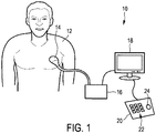
- Fig. 1 shows a schematic illustration of an ultrasound system 10 according to an embodiment, in particular a medical ultrasound three-dimensional imaging system.
- the ultrasound system 10 is applied to inspect a volume of an anatomical site, in particular an anatomical site of a patient 12.
- the ultrasound system 10 comprises an ultrasound probe 14 having at least one transducer array having a multitude of transducer elements for transmitting and/or receiving ultrasound waves.
- the transducer elements each can transmit ultrasound waves in form of at least one transmit impulse of a specific pulse duration, in particular a plurality of subsequent transmit pulses.
- the transducer elements can for example be arranged in a one-dimensional row, for example for providing a two-dimensional image that can be moved or swiveled around an axis mechanically. Further, the transducer elements may be arranged in a two-dimensional array, in particular for providing a multi-planar or three-dimensional image.
- the multitude of two-dimensional images, each along a specific acoustic line or scanning line, in particular scanning receive line, may be obtained in three different ways.
- the user might achieve the multitude of images via manual scanning.
- the ultrasound probe may comprise position-sensing devices that can keep track of a location and orientation of the scan lines or scan planes. However, this is currently not contemplated.
- the transducer may be automatically mechanically scanned within the ultrasound probe. This may be the case if a one dimensional transducer array is used.
- a phased two-dimensional array of transducers is located within the ultrasound probe and the ultrasound beams are electronically scanned.
- the ultrasound probe may be hand-held by the user of the system, for example medical staff or a doctor.
- the ultrasound probe 14 is applied to the body of the patient 12 so that an image of an anatomical site in the patient 12 is provided.
- the ultrasound system 10 has a controlling unit 16 that controls the provision of a three-dimensional image via the ultrasound system 10.
- the controlling unit 16 controls not only the acquisition of data via the transducer array of the ultrasound probe 14 but also signal and image processing that form the three-dimensional images out of the echoes of the ultrasound beams received by the transducer array of the ultrasound probe 14.
- the ultrasound system 10 further comprises a display 18 for displaying the three-dimensional images to the user.
- an input device 20 is provided that may comprise keys or a keyboard 22 and further inputting devices, for example a track ball 24.
- the input device 20 might be connected to the display 18 or directly to the controlling unit 16.
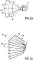
- Fig. 2a shows an example of a volume 50 relative to the ultrasound probe 14.
- the exemplary volume 50 depicted in this example is of a sector type, due to the transducer array of the ultrasound probe 14 being arranged as a phased two-dimensional electronically scanned array.
- the size of the volume 50 may be expressed by an elevation angle 52 and a lateral angle 54.
- a depth 56 of the volume 50 may be expressed by a so-called line time in seconds per line. That is the scanning time spent to scan a specific scanning line.
- Fig. 2b shows an illustrative example how the volume 50 may be divided into a multitude of slices 58 or two-dimensional images each acquired along a multitude of so-called scan lines 59.
- the two-dimensional transducer array of the ultrasound probe 14 is operated by a beam former in a way that the volume 50 is scanned along a multitude of these scan lines 58 sequentially.
- a single transmit beam might illuminate a multitude, for example four, receive scanning lines along which signals are acquired in parallel. If so, such sets of receive lines are then electronically scanned across the volume 50 sequentially.
- a resolution of a three-dimensional image processed out of the acquired two-dimensional images depends on a so-called line density which in turn depends on a spacing 60 between two adjacent scanning lines 59. In fact, it is the distance between two adjacent scan lines 59 within a slice 58 and, further, between the slices 58.
- the line density in the direction of the lateral extent and in the direction of the elevation extent is the same.
- the line density is measured in the form of degrees per line.
- Fig. 3 shows a schematic block diagram of the ultrasound system 10.
- the ultrasound system 10 comprises an ultrasound probe (PR) 14, the controlling unit (CU) 16, the display (DI) 18 and the input device (ID) 20.
- the probe 14 comprises a phased two-dimensional transducer array 26.
- the controlling unit (CU) 16 may comprise a central processing unit that may include analog and/or digital electronic circuits, a processor, microprocessor or the like to coordinate the whole image acquisition and provision.
- the controlling unit 16 comprises a herein called image acquisition controller 28.
- the image acquisition controller 28 does not need to be a separate entity or unit within the ultrasound system 10. It can be a part of the controlling unit 16 and generally be hardware or software implemented.
- the image acquisition controller 28 as part of the controlling unit 16 may control a beam former and, by this, what images of the volume 50 are taken and how these images are taken.
- the beam former 30 generates the voltages that drives the transducer array 26, determines parts repetition frequencies, it may scan, focus and apodize the transmitted beam and the reception or receive beam(s) and may further amplify filter and digitize the echo voltage stream returned by the transducer array 26.
- a herein called image acquisition part 32 of the image acquisition controller 28 of the controlling unit 16 may determine general scanning strategies.
- Such general strategies may include a desired volume acquisition rate, lateral extent of the volume, an elevation extent of the volume, maximum and minimum line densities, scanning line times and the line density as already explained above.
- the image acquisition part 32 does not need to be a separate entity or unit within the ultrasound system 10. It can be a part of the controlling unit 16 and generally be hardware or software implemented. The current distinction is made for illustrative purposes only.
- the image acquisition part 32 can also be implemented in, for example, the beam former 30 or the general controlling unit 16 or may be implemented as a software run on a data processing unit of the controller 16.
- the beam former 30 further receives the ultrasound signals from the transducer array 26 and forwards them as image signals.
- the ultrasound system 10 comprises a signal processor 34 that receives the image signals.
- the signal processor 34 is generally provided for analogue-to-digital-converting, digital filtering, for example, band pass filtering, as well as the detection and compression, for example a dynamic range reduction, of the received ultrasound echoes or image signals.
- the signal processor forwards image data.
- the ultrasound system 10 comprises an image processor 36 that converts image data received from the signal processor 34 into display data finally shown on the display 18.
- the image processor 36 receives the image data, preprocesses the image data and may store it in an image memory. These image data is then further post-processed to provide images most convenient to the user via the display 18.
- the image processor 36 may form the three-dimensional images out of a multitude of two-dimensional images acquired along the multitude of scan lines 59 in each slice 58.
- a user interface is generally depicted with reference numeral 38 and comprises the display 18 and the input device 20. It may also comprise further input devices, for example, a mouse or further buttons which may even be provided on the ultrasound probe 14 itself.
- a particular example for a three-dimensional ultrasound system which may apply the current invention is the CX50 CompactXtreme Ultrasound system sold by the applicant, in particular together with a X7-2t TEE transducer of the applicant or another transducer using the xMATRIX technology of the applicant.
- matrix transducer systems as found on Philips iE33 systems or mechanical 3D/4D transducer technology as found, for example, on the Philips iU22 and HD15 systems may apply the current invention. 10
- system inputs are made as preset or fixed parameters of the ultrasound system 10. These so-called system inputs in particular are a maximum line density, in minimum line density and a scan line time.
- the user may then input a target volume acquisition rate and, in particular, further specify the size of the volume to be scanned or region of interest in the form of a lateral extent and an elevation extent of the volume 50 to the ultrasound system 10.
- the user may input the lateral extent and the elevation extent directly as a numeric value, for example, 40 degrees. But, the user may also, for example, select a certain region via the user interface 38 on the display 18 which selection is then translated into numerical values for the lateral extent and elevation extent and forwarded to the image acquisition part 32.
- the system inputs may be a maximum line density of 3 degrees, a minimum line density of 0.75 degrees and a line time of 0.00005 seconds per line.
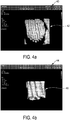
- Fig. 4a shows a first example display 40 as it may be shown to the user on the display 18 of the ultrasound system 10.
- a first large scanned volume 42 is shown as a three-dimensional image of the region of interest.
- the user has set a target volume acquisition rate to 25 Hz (1/seconds), further, the lateral extent is set to 40 degrees and the elevation extent is set to 40 degrees.
- the controller 28 can calculate the line density as 1.41 degrees per line via above-identified empirical formula. As this value is within the boundary conditions set via the minimum line density and maximum line density, the actual volume rate of 25 Hz can be maintained as desired.
- a second example display 44 is shown.
- an image of a smaller region of interest 46 is shown.
- the user has decided that a particular part of the volume 42 shown in the first example display 40 is of particular interest and may have marked it with a corresponding frame.
- the user may have directly inputted different values for the lateral and elevation extent of the volume.
- the desired volume rate may still be 25 Hz (1/seconds) to maintain a live or real time three-dimensional imaging.
- the lateral extent is set to 22 degrees and the elevation extent is set to 28 degrees.
- the controller 28 can now calculate the line density to 0.88 degrees per line given the same system inputs as identified above and in the first example. As this line density is within the boundary conditions, the actual volume acquisition rate equals the desired or target volume acquisition rate of 25 Hz. Hence, a live three-dimensional imaging is maintained since the total number of scanning lines 59 across the volume 50 is kept constant. Further, the user automatically has the technical benefit that the smaller region of interest 64 in the example display 44 is acquired with a significantly smaller line density.
- the spatial resolution of the smaller region of interest 64 is higher than the spatial resolution of the first larger region of interest 42.
- the volume acquisition rate is maintained at 25 Hz.
- live three-dimensional imaging is provided to the user after he has picked a smaller region of interest during use. If the user would turn back to the larger volume 42, the same applies vice versa.
- the acquisition rate will remain constant.
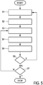
- Fig. 5 shows a schematic flow diagram of an embodiment of a method.
- the ultrasound system 10 scans the volume 50 along the scanning lines 59 with the transducer array and provides an ultrasound signal.
- the ultrasound signal is processed in the beam former 30 and the signal processor 34 to provide image data.
- the three-dimensional ultrasound image is displayed using the image data.
- step S6 it is determined whether the size of the volume to be scanned has changed. In particular, this is the case if the region of interest is changed by the user so that the lateral extent and/or the elevation extent of the volume change. If so, the new user input parameters are inputted into the controller 28 and the line density is recalculated in step S2. The scanning then continues with step S3.
- step S6 it may be further determined if the whole scanning process shall be stopped in a step S7. If so, a method ends, if not, scanning continues in step S3.
- a computer program may be stored/distributed on a suitable medium, such as an optical storage medium or a solid-state medium supplied together with or as part of other hardware, but may also be distributed in other forms, such as via the Internet or other wired or wireless telecommunication systems.
- a suitable medium such as an optical storage medium or a solid-state medium supplied together with or as part of other hardware, but may also be distributed in other forms, such as via the Internet or other wired or wireless telecommunication systems.
Description
- The present invention relates to an ultrasound system and method for providing a live three-dimensional image of a volume, for example an anatomical site of a patient. The present invention further relates to a computer program for implementing such method.
- In three-dimensional ultrasound imaging, or volume imaging, the acquisition of a three-dimensional image is accomplished by conducting many two-dimensional scans that slice through the volume of interest. Hence, a multitude of two-dimensional images is acquired that lie next to another. By proper image processing, a three-dimensional image of the volume of interest can be built out of the multitude of two-dimensional images. The three-dimensional information acquired from the multitude of two-dimensional images is displayed in proper form on a display for the user of the ultrasound system.
- Further, so-called live three-dimensional imaging, or 4D imaging, is often used in clinical applications. In live three-dimensional imaging, a real-time view on the volume can be acquired enabling a user to view moving parts of the anatomical site, for example a beating heart or else. In the clinical application of live three-dimensional imaging there is sometimes a need to image a relatively small area of the heart such as a single valve, or a septal defect, and there is sometimes the need to image a large area of the heart such as an entire ventricle.
- Hence, the so-called region of interest (ROI) and its size might change through a clinical application of live three-dimensional ultrasound imaging.
- In conventional praxis, the so-called line density, that is a dimension of the volume divided by the total number of scanning lines, specifically the receive scanning lines of a transducer array, is fixed. The line density is also a measure for the space between two adjacent scanning lines. Typically, the line density is expressed as a dimensional value per line, for example in degrees per line. In the case of a fixed line density, the acquisition rate of the volume changes as the region of interest is changed by a user. Larger volumes require more scanning lines or acoustic lines and, thus, the volume rate drops. However, in live three-dimensional imaging, the acquisition rate should be sufficiently high, that is larger than 20 Hz, in particular larger than 24 Hz, to provide a live and moving image. Hence, there is often provided a control for the user to change the line density to compensate for the drop of the acquisition rate. But this is a manual step that can be cumbersome and time-consuming for the user.
- Therefore, methods for automatically changing the line density have been contemplated. The reference
US 2008/0089571 A1 discloses an ultrasonic probe to scan a three-dimensional region using ultrasonic beams by raising the scanning line density of the transmission of ultrasonic beams for a region of interest compared to the scanning line density of the transmission of ultrasonic beams for regions other than the region of interest among three-dimensional regions. - A closest prior art for the invention is referred to in
WO 2005/034760 A1 . The document refers to an ultrasound imaging system for providing a three-dimensional image of a volume comprising - a transducer means configured to provide an ultrasound receive signal,
- a scanning means configured to control the transducer means to scan the volume along a multitude of scanning lines, to receive the ultrasound receive signal and to provide an image signal,
- a signal processor configured to receive the image signal and to provide image data,
- an image processor configured to receive the image data from the signal processor and to provide display data,
- a display configured to receive the display data and to provide the three-dimensional image, and
- a controller for controlling the scanning means,
- to receive a size of the volume via user input, wherein the size of the volume is in the form of a lateral extent, an elevation extent and a depth, and
- to adjust a density of the scanning lines within the volume as a function of a size of the volume while maintaining a total number of scanning lines across the volume.
- There is a need to further improve such three-dimensional ultrasound systems.
- It is an object of the present invention to provide an improved ultrasound system and method. It is a further object of the present invention to provide a computer program for implementing such method.
- In a first aspect of the present invention, an ultrasound imaging system according to claim 1 is presented.
- In a further aspect of the present invention a method according to claim 7 is presented. size of the volume while maintaining a total number of scanning lines across the volume, scanning the volume along the scanning lines with a transducer array providing an ultrasound signal, processing the ultrasound signal to provide image data, and displaying the three-dimensional ultrasound image using the image data.
- In a further aspect of the present invention a computer program according to claim 8 is presented.
- The basic idea of the invention is to adjust the line density automatically as a function of the size of the volume or region of interest. By this, a constant and sufficiently high volume acquisition rate can be provided to the user as they change the size of the region of interest to fit their need without any other adjustments. In live three-dimensional imaging there is a need to maintain a sufficiently high volume rate to properly visualize the dynamic nature of the anatomy inspected. When changing between a large region of interest and a small region of interest, there is willingness on the part of the clinician to decrease the image resolution when imaging large regions of interest and to increase the resolution when smaller regions of interest are to be imaged.
- Hence, a significant technical benefit of the present invention is that if a size of the region of interest or volume is reduced by the user to image smaller structures, the imaging spatial resolution increases owing to the higher density of the acoustic lines within the region of interest. This is because the total number of scanning lines is kept constant. If the region of interest becomes smaller, the density of the acoustic lines must become higher.
- Further, this allows the ultrasound system to maintain high volume acquisition rates across both small and large regions of interest by spreading the scanning lines slicing through the volume as the size of the volume increases, by effectively maintaining a fixed number of acoustic lines or scanning lines and hence a fixed volume acquisition rate. This is regardless of the size of the region of interest.
- Preferred embodiments of the invention are defined in the dependent claims. It shall be understood that the claimed method has similar and/or identical preferred embodiments as the claimed device and as defined in the dependent claims.
- In one embodiment, the controller is further configured to adjust the density of the scanning lines as a function of a target volume acquisition rate. Hence, a target volume acquisition rate or desired volume acquisition rate is inputted into the controller. In particular, the user might set the target volume acquisition rate to 24 Hz to make sure to being provided with a live three-dimensional image. However, a target acquisition rate for live three-dimensional imaging might also be set automatically, in particular t a value equal or greater than 24 Hz.
- The controller is configured to receive the target volume acquisition rate via a user input. By this, a controller is provided to the user which enables the user to choose a target volume acquisition rate to selectively trade-off acquisition rate with imaging spatial resolution as desired. By this, there is achieved a technical effect in that the user may give up live three-dimensional imaging and set a target volume acquisition rate to a lower rate, for example 10 Hz, but with a significantly higher imaging resolution. This is may be of advantage if the user might want to inspect a non-moving or non-dynamic site in the body of the patient with good resolution.
- The controller is configured to receive the size of the volume in the form of a lateral extent in degrees, an elevation extent in degrees and a depth expressed by a scanning time of each scanning line. By scanning time it is meant the time the ultrasound system spends to acquire or receive an ultrasound echo response image along each scanning line. The scanning time, therefore, is usually inputted in the form of time per line. As scanning time has an effect on the time waited between a sent ultrasound impulse and the answer received by a reflection from the inspected tissue, it is directly proportional to the depth of the volume or region of interest. In particular, the controller is configured to receive the lateral extent and the elevation extent via user input. Hence, the user might vary the lateral extent and the elevation extent to narrow the image acquisition to a smaller region of interest. Further, the controller may be configured to receive the scanning time of each scanning line as a preset or fixed parameter of the ultrasound system. By presetting the scanning time for each scanning line and keeping the total number of scanning lines constant, the ultrasound system is possible to maintain a constant volume acquisition rate during scanning.
- In a further embodiment, the controller is further configured to adjust the density of the scanning lines based on the following empirical formula:

- The controller is further configured to apply a boundary condition on the adjusted density of the scanning lines. By this, it can be secured that the adjusted line density is kept only in a practical range of densities. The boundary condition is a maximum boundary condition or a maximum line density. For example, given that the total number of acoustic lines is fixed, the maximum line density might be set so that a total number of lines multiplied with the maximum line density does not exceed a maximum angle the transducer array is able to work within. As a further example, the maximum line density might be set to an angle so that the receive beams along adjacent scanning lines do not drift apart too much so that even small objects in a deep position in the volume can still be detected. Additionally or alternatively, the boundary condition may be a minimum boundary condition or a minimum line density. By this, for example, it might be secured that the line density is not lower than a minimum line density or line spacing achievable with a certain transducer array.
- The controller is further configured to adjust the size of the volume to meet the boundary condition. For example, if the user sets the lateral extent and the elevation extent of the region of interest too large, the controller may override the selection and set some to maximum values instead to meet boundary condition.
- In a further embodiment, the controller is configured to adjust an actual volume acquisition rate to meet the boundary condition. However, as the controller shall usually maintain the target volume acquisition rate, this action might be the last measure to meet the boundary conditions. Further, adjusting the actual volume acquisition rate may be combined with the measure of adjusting the size of the volume to meet the boundary condition. In particular, the controller may be configured to lower the actual volume acquisition rate not below 24 Hz to maintain a live three-dimensional imaging under any circumstances. The controller may then start to lower the size of the volume to meet the boundary condition.
- These and other aspects of the invention will be apparent from and elucidated with reference to the embodiment(s) described hereinafter. In the following drawings
-
Fig. 1 shows a schematic illustration of an ultrasound system according to an embodiment; -
Fig. 2a shows a schematic representation of a region of interest in relation to an ultrasonic probe; -
Fig. 2b shows a schematic example how a multitude of scanning lines may spread through the volume inFig. 2a ; -
Fig. 3 shows a schematic block diagram of the ultrasound system according to the embodiment; -
Fig. 4a shows an example of a display with a large region of interest; -
Fig. 4b shows another example of a display with a region of interest smaller than that ofFig. 4a ; and -
Fig. 5 shows a schematic flow diagram of a method according to an embodiment. -
Fig. 1 shows a schematic illustration of anultrasound system 10 according to an embodiment, in particular a medical ultrasound three-dimensional imaging system. Theultrasound system 10 is applied to inspect a volume of an anatomical site, in particular an anatomical site of apatient 12. Theultrasound system 10 comprises anultrasound probe 14 having at least one transducer array having a multitude of transducer elements for transmitting and/or receiving ultrasound waves. In one example, the transducer elements each can transmit ultrasound waves in form of at least one transmit impulse of a specific pulse duration, in particular a plurality of subsequent transmit pulses. The transducer elements can for example be arranged in a one-dimensional row, for example for providing a two-dimensional image that can be moved or swiveled around an axis mechanically. Further, the transducer elements may be arranged in a two-dimensional array, in particular for providing a multi-planar or three-dimensional image. - In general, the multitude of two-dimensional images, each along a specific acoustic line or scanning line, in particular scanning receive line, may be obtained in three different ways. First, the user might achieve the multitude of images via manual scanning. In this case, the ultrasound probe may comprise position-sensing devices that can keep track of a location and orientation of the scan lines or scan planes. However, this is currently not contemplated. Second, the transducer may be automatically mechanically scanned within the ultrasound probe. This may be the case if a one dimensional transducer array is used. Third, and preferably, a phased two-dimensional array of transducers is located within the ultrasound probe and the ultrasound beams are electronically scanned. The ultrasound probe may be hand-held by the user of the system, for example medical staff or a doctor. The
ultrasound probe 14 is applied to the body of the patient 12 so that an image of an anatomical site in thepatient 12 is provided. - Further, the
ultrasound system 10 has a controllingunit 16 that controls the provision of a three-dimensional image via theultrasound system 10. As will be explained in further detail below, the controllingunit 16 controls not only the acquisition of data via the transducer array of theultrasound probe 14 but also signal and image processing that form the three-dimensional images out of the echoes of the ultrasound beams received by the transducer array of theultrasound probe 14. - The
ultrasound system 10 further comprises adisplay 18 for displaying the three-dimensional images to the user. Further, aninput device 20 is provided that may comprise keys or akeyboard 22 and further inputting devices, for example atrack ball 24. Theinput device 20 might be connected to thedisplay 18 or directly to the controllingunit 16. -
Fig. 2a shows an example of avolume 50 relative to theultrasound probe 14. Theexemplary volume 50 depicted in this example is of a sector type, due to the transducer array of theultrasound probe 14 being arranged as a phased two-dimensional electronically scanned array. Hence, the size of thevolume 50 may be expressed by anelevation angle 52 and alateral angle 54. Adepth 56 of thevolume 50 may be expressed by a so-called line time in seconds per line. That is the scanning time spent to scan a specific scanning line. -
Fig. 2b shows an illustrative example how thevolume 50 may be divided into a multitude ofslices 58 or two-dimensional images each acquired along a multitude of so-calledscan lines 59. During image acquisition, the two-dimensional transducer array of theultrasound probe 14 is operated by a beam former in a way that thevolume 50 is scanned along a multitude of thesescan lines 58 sequentially. However, in multi-line receive processing, a single transmit beam might illuminate a multitude, for example four, receive scanning lines along which signals are acquired in parallel. If so, such sets of receive lines are then electronically scanned across thevolume 50 sequentially. - Hence, a resolution of a three-dimensional image processed out of the acquired two-dimensional images depends on a so-called line density which in turn depends on a
spacing 60 between two adjacent scanning lines 59. In fact, it is the distance between twoadjacent scan lines 59 within aslice 58 and, further, between theslices 58. As a result, the line density in the direction of the lateral extent and in the direction of the elevation extent is the same. Hence, the line density is measured in the form of degrees per line. -
Fig. 3 shows a schematic block diagram of theultrasound system 10. As already laid out above, theultrasound system 10 comprises an ultrasound probe (PR) 14, the controlling unit (CU) 16, the display (DI) 18 and the input device (ID) 20. As further laid out above, theprobe 14 comprises a phased two-dimensional transducer array 26. In general, the controlling unit (CU) 16 may comprise a central processing unit that may include analog and/or digital electronic circuits, a processor, microprocessor or the like to coordinate the whole image acquisition and provision. Further, the controllingunit 16 comprises a herein calledimage acquisition controller 28. However, it has to be understood that theimage acquisition controller 28 does not need to be a separate entity or unit within theultrasound system 10. It can be a part of the controllingunit 16 and generally be hardware or software implemented. The current distinction is made for illustrative purposes only. Theimage acquisition controller 28 as part of the controllingunit 16 may control a beam former and, by this, what images of thevolume 50 are taken and how these images are taken. The beam former 30 generates the voltages that drives thetransducer array 26, determines parts repetition frequencies, it may scan, focus and apodize the transmitted beam and the reception or receive beam(s) and may further amplify filter and digitize the echo voltage stream returned by thetransducer array 26. Further, a herein calledimage acquisition part 32 of theimage acquisition controller 28 of the controllingunit 16 may determine general scanning strategies. Such general strategies may include a desired volume acquisition rate, lateral extent of the volume, an elevation extent of the volume, maximum and minimum line densities, scanning line times and the line density as already explained above. Again, theimage acquisition part 32 does not need to be a separate entity or unit within theultrasound system 10. It can be a part of the controllingunit 16 and generally be hardware or software implemented. The current distinction is made for illustrative purposes only. Theimage acquisition part 32 can also be implemented in, for example, the beam former 30 or the general controllingunit 16 or may be implemented as a software run on a data processing unit of thecontroller 16. - The beam former 30 further receives the ultrasound signals from the
transducer array 26 and forwards them as image signals. - Further, the
ultrasound system 10 comprises asignal processor 34 that receives the image signals. Thesignal processor 34 is generally provided for analogue-to-digital-converting, digital filtering, for example, band pass filtering, as well as the detection and compression, for example a dynamic range reduction, of the received ultrasound echoes or image signals. The signal processor forwards image data. - Further, the
ultrasound system 10 comprises animage processor 36 that converts image data received from thesignal processor 34 into display data finally shown on thedisplay 18. In particular, theimage processor 36 receives the image data, preprocesses the image data and may store it in an image memory. These image data is then further post-processed to provide images most convenient to the user via thedisplay 18. In the current case, in particular, theimage processor 36 may form the three-dimensional images out of a multitude of two-dimensional images acquired along the multitude ofscan lines 59 in eachslice 58. - A user interface is generally depicted with
reference numeral 38 and comprises thedisplay 18 and theinput device 20. It may also comprise further input devices, for example, a mouse or further buttons which may even be provided on theultrasound probe 14 itself. - A particular example for a three-dimensional ultrasound system which may apply the current invention is the CX50 CompactXtreme Ultrasound system sold by the applicant, in particular together with a X7-2t TEE transducer of the applicant or another transducer using the xMATRIX technology of the applicant. In general, matrix transducer systems as found on Philips iE33 systems or mechanical 3D/4D transducer technology as found, for example, on the Philips iU22 and HD15 systems may apply the current invention. 10
- In use, general system inputs are made as preset or fixed parameters of the
ultrasound system 10. These so-called system inputs in particular are a maximum line density, in minimum line density and a scan line time. The user may then input a target volume acquisition rate and, in particular, further specify the size of the volume to be scanned or region of interest in the form of a lateral extent and an elevation extent of thevolume 50 to theultrasound system 10. The user may input the lateral extent and the elevation extent directly as a numeric value, for example, 40 degrees. But, the user may also, for example, select a certain region via theuser interface 38 on thedisplay 18 which selection is then translated into numerical values for the lateral extent and elevation extent and forwarded to theimage acquisition part 32. - Based on these inputs, the line density is characterized according to the following empirical formula:

- For example, the system inputs may be a maximum line density of 3 degrees, a minimum line density of 0.75 degrees and a line time of 0.00005 seconds per line.
-
Fig. 4a shows afirst example display 40 as it may be shown to the user on thedisplay 18 of theultrasound system 10. On the display, a first large scannedvolume 42 is shown as a three-dimensional image of the region of interest. - In this example, the user has set a target volume acquisition rate to 25 Hz (1/seconds), further, the lateral extent is set to 40 degrees and the elevation extent is set to 40 degrees. With these values as user inputs and the above-identified system inputs, the
controller 28 can calculate the line density as 1.41 degrees per line via above-identified empirical formula. As this value is within the boundary conditions set via the minimum line density and maximum line density, the actual volume rate of 25 Hz can be maintained as desired. - In
Fig. 4b a second example display 44 is shown. In this display 44, an image of a smaller region ofinterest 46 is shown. For example, the user has decided that a particular part of thevolume 42 shown in thefirst example display 40 is of particular interest and may have marked it with a corresponding frame. Alternatively, the user may have directly inputted different values for the lateral and elevation extent of the volume. - In the second example display 44, the desired volume rate may still be 25 Hz (1/seconds) to maintain a live or real time three-dimensional imaging. The lateral extent is set to 22 degrees and the elevation extent is set to 28 degrees. The
controller 28 can now calculate the line density to 0.88 degrees per line given the same system inputs as identified above and in the first example. As this line density is within the boundary conditions, the actual volume acquisition rate equals the desired or target volume acquisition rate of 25 Hz. Hence, a live three-dimensional imaging is maintained since the total number ofscanning lines 59 across thevolume 50 is kept constant. Further, the user automatically has the technical benefit that the smaller region of interest 64 in the example display 44 is acquired with a significantly smaller line density. Hence, the spatial resolution of the smaller region of interest 64 is higher than the spatial resolution of the first larger region ofinterest 42. However, since theultrasound system 10 has maintained a constant total number ofscanning lines 59, the volume acquisition rate is maintained at 25 Hz. Hence, live three-dimensional imaging is provided to the user after he has picked a smaller region of interest during use. If the user would turn back to thelarger volume 42, the same applies vice versa. In particular, even though the user has enlarged the region of interest, the acquisition rate will remain constant. -
Fig. 5 shows a schematic flow diagram of an embodiment of a method. After the method has been started, the first step S1 is carried out. In this step, the controller receives the parameters determining the size of thevolume 50. These parameters are received as user inputs via theinput device 20. Further, system inputs have already been made into theultrasound system 10. System inputs remain constant over a scan of an anatomical site, wherein the user inputs may vary over time during the particular scan. The system inputs are a maximum line density, a minimum line density and a line time. The user inputs are a desired or target volume acquisition rate, a lateral extent of thevolume 50 and an elevation extent of thevolume 50. Then, in a step S2, thecontroller 28 calculates and adjusts the line density according to the following formula as laid out above:
- By this, the line density in degrees per line is calculated. Then, in a step S3, the
ultrasound system 10 scans thevolume 50 along thescanning lines 59 with the transducer array and provides an ultrasound signal. In step S4, the ultrasound signal is processed in the beam former 30 and thesignal processor 34 to provide image data. Last, in a step S5, the three-dimensional ultrasound image is displayed using the image data. - Further, optionally, during use and in step S6, it is determined whether the size of the volume to be scanned has changed. In particular, this is the case if the region of interest is changed by the user so that the lateral extent and/or the elevation extent of the volume change. If so, the new user input parameters are inputted into the
controller 28 and the line density is recalculated in step S2. The scanning then continues with step S3. - If the size of the volume has not changed in step S6, it may be further determined if the whole scanning process shall be stopped in a step S7. If so, a method ends, if not, scanning continues in step S3.
- While the invention has been illustrated and described in detail in the drawings and foregoing description, such illustration and description are to be considered illustrative or exemplary and not restrictive; the invention is not limited to the disclosed embodiments. Other variations to the disclosed embodiments can be understood and effected by those skilled in the art in practicing the claimed invention, from a study of the drawings, the disclosure, and the appended claims.
- In the claims, the word "comprising" does not exclude other elements or steps, and the indefinite article "a" or "an" does not exclude a plurality. A single element or other unit may fulfill the functions of several items recited in the claims. The mere fact that certain measures are recited in mutually different dependent claims does not indicate that a combination of these measures cannot be used to advantage.
- A computer program may be stored/distributed on a suitable medium, such as an optical storage medium or a solid-state medium supplied together with or as part of other hardware, but may also be distributed in other forms, such as via the Internet or other wired or wireless telecommunication systems.
- Any reference signs in the claims should not be construed as limiting the scope.
Claims (8)
- An ultrasound imaging system (10) for providing a three-dimensional image of a volume (50), the ultrasound imaging system comprising:a transducer array (26) configured to provide an ultrasound receive signal;a beam former configured to control the transducer array to scan the volume (50) along a multitude of scanning lines (59), and further configured to receive the ultrasound receive signal and to provide an image signal;a signal processor (34) configured to receive the image signal and to provide image data;an image processor (36) configured to receive the image data from the signal processor (34) and to provide display data;a display (18) configured to receive the display data and to provide the three-dimensional image; anda controller (28) for controlling the beam former (30),wherein the controller (28) is configured to:- receive a size of the volume (50) and a target acquisition rate for said volume via user input, wherein the size of the volume is in the form of a lateral extent in degrees, an elevation extent in degrees and a depth expressed by a scanning time of each scanning line,- adjust the density (60) of the scanning lines (59) within the volume (50) as a function of the size of the volume (50) while maintaining the total number of scanning lines (59) across the volume (50) constant and the density (60) of the scanning lines (59) within boundary conditions set as maximum and minimum scanning line densities determined by the transducer array (26), and- adjust the actual size of the volume (50), overriding a user selection, so that the density (60) of the scanning lines (59) meets the boundary conditions.
- The system of claim 1, wherein the controller (28) is configured to receive the scanning time of each scanning line as a preset parameter of the ultrasound system.
- The system of any preceding claim, wherein the controller (28) is configured to receive the total number of scanning lines (59) as a preset parameter of the ultrasound system.
- The system of any preceding claim, wherein the controller (28) is further configured to adjust the density (60) of the scanning lines (59) based on the following empirical formula:

- The system of any preceding claim, wherein the controller (28) is configured to adjust the actual volume acquisition rate in combination with the actual size of the volume sufficiently to meet the boundary conditions.
- The system of claim 5, wherein the controller (28) is configured to first lower the actual volume acquisition rate to a predetermined minimum rate, and then start to lower the actual size of the volume to meet the boundary conditions.
- A method for providing a three-dimensional ultrasound image of a volume (50), wherein the volume (50) is scanned along a multitude of scanning lines (59), the method comprising the following steps:- scanning (S3) the volume (50) along the scanning lines (59) with a transducer array (26) providing an ultrasound signal;- processing (S4) the ultrasound signal to provide image data; and- displaying (S5) the three-dimensional ultrasound image using the image data; wherein the method further comprises the steps of:- receiving (S1) a size of the volume (50) and a target acquisition rate for said volume via user input, wherein the size of the volume is in the form of a lateral extent in degrees, an elevation extent in degrees and a depth expressed by a scanning time of each scanning line,- adjusting (S2) the density of the scanning lines (59) within the volume (50) as a function of the size of the volume (50) while maintaining the total number of scanning lines (59) across the volume (50) constant and the density (60) of the scanning lines (59) within boundary conditions set as maximum and minimum scanning line densities determined by the transducer array (26), and- adjusting the actual size of the volume (50), overriding a user selection, so that the density (60) of the scanning lines (59) meets the boundary conditions.
- A computer program comprising program code means for causing a computer to carry out the steps of the method as claimed in claim 7 when said computer program is carried out on a computer.
Applications Claiming Priority (2)
| Application Number | Priority Date | Filing Date | Title |
|---|---|---|---|
| US201161557955P | 2011-11-10 | 2011-11-10 | |
| PCT/IB2012/056088 WO2013068894A1 (en) | 2011-11-10 | 2012-11-01 | Steady frame rate volumetric ultrasound imaging |
Publications (2)
| Publication Number | Publication Date |
|---|---|
| EP2748627A1 EP2748627A1 (en) | 2014-07-02 |
| EP2748627B1 true EP2748627B1 (en) | 2021-04-07 |
Family
ID=47172849
Family Applications (1)
| Application Number | Title | Priority Date | Filing Date |
|---|---|---|---|
| EP12784349.8A Active EP2748627B1 (en) | 2011-11-10 | 2012-11-01 | Steady frame rate volumetric ultrasound imaging |
Country Status (8)
| Country | Link |
|---|---|
| US (1) | US10939895B2 (en) |
| EP (1) | EP2748627B1 (en) |
| JP (1) | JP6571332B2 (en) |
| CN (1) | CN103946717B (en) |
| BR (1) | BR112014011024A2 (en) |
| IN (1) | IN2014CN03623A (en) |
| MX (1) | MX2014005545A (en) |
| WO (1) | WO2013068894A1 (en) |
Families Citing this family (6)
| Publication number | Priority date | Publication date | Assignee | Title |
|---|---|---|---|---|
| JP2016016022A (en) * | 2014-07-04 | 2016-02-01 | 株式会社東芝 | Ultrasonic diagnostic equipment |
| CN108027437B (en) * | 2015-09-10 | 2022-07-05 | 皇家飞利浦有限公司 | Ultrasound system with wide depth and detailed viewing |
| JP6651316B2 (en) * | 2015-09-16 | 2020-02-19 | キヤノンメディカルシステムズ株式会社 | Ultrasound diagnostic equipment |
| JP7159046B2 (en) * | 2015-12-15 | 2022-10-24 | コリンダス、インコーポレイテッド | System and method for controlling x-ray frame rate of imaging system |
| EP3469993A1 (en) | 2017-10-16 | 2019-04-17 | Koninklijke Philips N.V. | An ultrasound imaging system and method |
| US20190167231A1 (en) * | 2017-12-01 | 2019-06-06 | Sonocine, Inc. | System and method for ultrasonic tissue screening |
Family Cites Families (19)
| Publication number | Priority date | Publication date | Assignee | Title |
|---|---|---|---|---|
| JPH04152939A (en) | 1990-10-17 | 1992-05-26 | Hitachi Medical Corp | Ultrasonic diagnostic device |
| US5793701A (en) | 1995-04-07 | 1998-08-11 | Acuson Corporation | Method and apparatus for coherent image formation |
| JPH09192130A (en) * | 1996-01-12 | 1997-07-29 | Aloka Co Ltd | Ultrasonic diagnostic equipment |
| JP3723663B2 (en) * | 1997-07-15 | 2005-12-07 | フクダ電子株式会社 | Ultrasonic diagnostic equipment |
| EP1162476A1 (en) | 2000-06-06 | 2001-12-12 | Kretztechnik Aktiengesellschaft | Method for examining objects with ultrasound |
| US6468216B1 (en) | 2000-08-24 | 2002-10-22 | Kininklijke Philips Electronics N.V. | Ultrasonic diagnostic imaging of the coronary arteries |
| JP2003010182A (en) * | 2001-06-19 | 2003-01-14 | Ge Medical Systems Global Technology Co Llc | Ultrasonographic method and ultrasonographic device |
| US7758508B1 (en) | 2002-11-15 | 2010-07-20 | Koninklijke Philips Electronics, N.V. | Ultrasound-imaging systems and methods for a user-guided three-dimensional volume-scan sequence |
| JP2004290249A (en) * | 2003-03-25 | 2004-10-21 | Fuji Photo Film Co Ltd | Ultrasonic imaging apparatus and ultrasonic imaging method |
| CN1764849B (en) * | 2003-03-27 | 2010-05-26 | 皇家飞利浦电子股份有限公司 | Guidance of invasive medical devices by wide view three dimensional ultrasonic imaging |
| WO2005034760A1 (en) | 2003-10-08 | 2005-04-21 | Koninklijke Philips Electronics, N.V. | Improved ultrasonic volumetric imaging by coordination of acoustic sampling resolution, volumetric line density and volume imaging rate |
| JP2007512870A (en) | 2003-11-20 | 2007-05-24 | コーニンクレッカ フィリップス エレクトロニクス エヌ ヴィ | Imaging ultrasound diagnostics with automatic adjustment of beamforming |
| US20070078342A1 (en) | 2003-11-21 | 2007-04-05 | Koninklijke Philips Electronics N.V. | Ultrasound imaging system and method having adaptive selection of image frame rate and/or number of echo samples averaged |
| EP1697759B1 (en) | 2003-12-16 | 2010-11-03 | Koninklijke Philips Electronics N.V. | Ultrasonic diagnostic imaging method and system with an automatic control of resolution and frame rate |
| US20050228280A1 (en) | 2004-03-31 | 2005-10-13 | Siemens Medical Solutions Usa, Inc. | Acquisition and display methods and systems for three-dimensional ultrasound imaging |
| US20070007680A1 (en) | 2005-07-05 | 2007-01-11 | Fina Technology, Inc. | Methods for controlling polyethylene rheology |
| JP4969985B2 (en) * | 2006-10-17 | 2012-07-04 | 株式会社東芝 | Ultrasonic diagnostic apparatus and control program for ultrasonic diagnostic apparatus |
| KR100949059B1 (en) | 2006-10-17 | 2010-03-25 | 주식회사 메디슨 | Ultrasound system and method for forming ultrasound image |
| JP5366385B2 (en) * | 2007-09-26 | 2013-12-11 | 株式会社東芝 | Ultrasonic diagnostic apparatus and ultrasonic scanning program |
-
2012
- 2012-11-01 MX MX2014005545A patent/MX2014005545A/en unknown
- 2012-11-01 CN CN201280055160.5A patent/CN103946717B/en active Active
- 2012-11-01 WO PCT/IB2012/056088 patent/WO2013068894A1/en active Application Filing
- 2012-11-01 BR BR112014011024A patent/BR112014011024A2/en not_active IP Right Cessation
- 2012-11-01 EP EP12784349.8A patent/EP2748627B1/en active Active
- 2012-11-01 IN IN3623CHN2014 patent/IN2014CN03623A/en unknown
- 2012-11-01 US US14/356,182 patent/US10939895B2/en active Active
- 2012-11-01 JP JP2014540590A patent/JP6571332B2/en active Active
Non-Patent Citations (1)
| Title |
|---|
| None * |
Also Published As
| Publication number | Publication date |
|---|---|
| US10939895B2 (en) | 2021-03-09 |
| MX2014005545A (en) | 2014-05-30 |
| BR112014011024A2 (en) | 2017-04-25 |
| EP2748627A1 (en) | 2014-07-02 |
| CN103946717A (en) | 2014-07-23 |
| CN103946717B (en) | 2016-12-21 |
| IN2014CN03623A (en) | 2015-09-04 |
| JP2014534885A (en) | 2014-12-25 |
| WO2013068894A1 (en) | 2013-05-16 |
| US20140358006A1 (en) | 2014-12-04 |
| JP6571332B2 (en) | 2019-09-04 |
Similar Documents
| Publication | Publication Date | Title |
|---|---|---|
| EP2748627B1 (en) | Steady frame rate volumetric ultrasound imaging | |
| KR101140525B1 (en) | Method and apparatus for extending an ultrasound image field of view | |
| US10335118B2 (en) | Ultrasonic diagnostic apparatus, medical image processing apparatus, and medical image parallel display method | |
| EP2994053B1 (en) | 3d ultrasound imaging system | |
| EP3013243B1 (en) | Elastography measurement system and method | |
| US9192352B2 (en) | Ultrasonic diagnostic apparatus, medical image diagnostic apparatus, and medical image processing method | |
| CN109310399B (en) | Medical ultrasonic image processing apparatus | |
| US9743910B2 (en) | Ultrasonic diagnostic apparatus, ultrasonic image processing apparatus, medical image diagnostic apparatus, and medical image processing apparatus | |
| JPH06292667A (en) | Method and device for finding volume of celom in real-time system | |
| RU2659021C2 (en) | Ultrasound imaging system and an ultrasound imaging method | |
| US11308609B2 (en) | System and methods for sequential scan parameter selection | |
| CN112890853A (en) | System and method for joint scan parameter selection | |
| JP2010022565A (en) | Ultrasonic diagnosing system | |
| JP2021503999A (en) | Ultrasound lung evaluation | |
| US20130211254A1 (en) | Ultrasound acquisition | |
| EP2748630B1 (en) | Improving large volume three-dimensional ultrasound imaging | |
| KR102545007B1 (en) | Ultrasound imaging apparatus and controlling method for the same | |
| KR101117003B1 (en) | Ultrasound system and method of providing 3-dimensional ultrasound images using volume slices | |
| US20240000430A1 (en) | Processing ultrasound scan data |
Legal Events
| Date | Code | Title | Description |
|---|---|---|---|
| PUAI | Public reference made under article 153(3) epc to a published international application that has entered the european phase |
Free format text: ORIGINAL CODE: 0009012 |
|
| 17P | Request for examination filed |
Effective date: 20140324 |
|
| AK | Designated contracting states |
Kind code of ref document: A1 Designated state(s): AL AT BE BG CH CY CZ DE DK EE ES FI FR GB GR HR HU IE IS IT LI LT LU LV MC MK MT NL NO PL PT RO RS SE SI SK SM TR |
|
| DAX | Request for extension of the european patent (deleted) | ||
| 17Q | First examination report despatched |
Effective date: 20160708 |
|
| STAA | Information on the status of an ep patent application or granted ep patent |
Free format text: STATUS: EXAMINATION IS IN PROGRESS |
|
| RAP1 | Party data changed (applicant data changed or rights of an application transferred) |
Owner name: KONINKLIJKE PHILIPS N.V. |
|
| GRAP | Despatch of communication of intention to grant a patent |
Free format text: ORIGINAL CODE: EPIDOSNIGR1 |
|
| STAA | Information on the status of an ep patent application or granted ep patent |
Free format text: STATUS: GRANT OF PATENT IS INTENDED |
|
| INTG | Intention to grant announced |
Effective date: 20201026 |
|
| GRAS | Grant fee paid |
Free format text: ORIGINAL CODE: EPIDOSNIGR3 |
|
| GRAA | (expected) grant |
Free format text: ORIGINAL CODE: 0009210 |
|
| STAA | Information on the status of an ep patent application or granted ep patent |
Free format text: STATUS: THE PATENT HAS BEEN GRANTED |
|
| AK | Designated contracting states |
Kind code of ref document: B1 Designated state(s): AL AT BE BG CH CY CZ DE DK EE ES FI FR GB GR HR HU IE IS IT LI LT LU LV MC MK MT NL NO PL PT RO RS SE SI SK SM TR |
|
| REG | Reference to a national code |
Ref country code: GB Ref legal event code: FG4D |
|
| REG | Reference to a national code |
Ref country code: AT Ref legal event code: REF Ref document number: 1380387 Country of ref document: AT Kind code of ref document: T Effective date: 20210415 Ref country code: CH Ref legal event code: EP |
|
| REG | Reference to a national code |
Ref country code: DE Ref legal event code: R096 Ref document number: 602012075127 Country of ref document: DE |
|
| REG | Reference to a national code |
Ref country code: IE Ref legal event code: FG4D |
|
| REG | Reference to a national code |
Ref country code: GB Ref legal event code: 746 Effective date: 20210602 |
|
| REG | Reference to a national code |
Ref country code: DE Ref legal event code: R084 Ref document number: 602012075127 Country of ref document: DE |
|
| REG | Reference to a national code |
Ref country code: LT Ref legal event code: MG9D |
|
| REG | Reference to a national code |
Ref country code: NL Ref legal event code: MP Effective date: 20210407 Ref country code: AT Ref legal event code: MK05 Ref document number: 1380387 Country of ref document: AT Kind code of ref document: T Effective date: 20210407 |
|
| PG25 | Lapsed in a contracting state [announced via postgrant information from national office to epo] |
Ref country code: BG Free format text: LAPSE BECAUSE OF FAILURE TO SUBMIT A TRANSLATION OF THE DESCRIPTION OR TO PAY THE FEE WITHIN THE PRESCRIBED TIME-LIMIT Effective date: 20210707 Ref country code: AT Free format text: LAPSE BECAUSE OF FAILURE TO SUBMIT A TRANSLATION OF THE DESCRIPTION OR TO PAY THE FEE WITHIN THE PRESCRIBED TIME-LIMIT Effective date: 20210407 Ref country code: HR Free format text: LAPSE BECAUSE OF FAILURE TO SUBMIT A TRANSLATION OF THE DESCRIPTION OR TO PAY THE FEE WITHIN THE PRESCRIBED TIME-LIMIT Effective date: 20210407 Ref country code: LT Free format text: LAPSE BECAUSE OF FAILURE TO SUBMIT A TRANSLATION OF THE DESCRIPTION OR TO PAY THE FEE WITHIN THE PRESCRIBED TIME-LIMIT Effective date: 20210407 Ref country code: NL Free format text: LAPSE BECAUSE OF FAILURE TO SUBMIT A TRANSLATION OF THE DESCRIPTION OR TO PAY THE FEE WITHIN THE PRESCRIBED TIME-LIMIT Effective date: 20210407 Ref country code: FI Free format text: LAPSE BECAUSE OF FAILURE TO SUBMIT A TRANSLATION OF THE DESCRIPTION OR TO PAY THE FEE WITHIN THE PRESCRIBED TIME-LIMIT Effective date: 20210407 |
|
| PG25 | Lapsed in a contracting state [announced via postgrant information from national office to epo] |
Ref country code: PT Free format text: LAPSE BECAUSE OF FAILURE TO SUBMIT A TRANSLATION OF THE DESCRIPTION OR TO PAY THE FEE WITHIN THE PRESCRIBED TIME-LIMIT Effective date: 20210809 Ref country code: NO Free format text: LAPSE BECAUSE OF FAILURE TO SUBMIT A TRANSLATION OF THE DESCRIPTION OR TO PAY THE FEE WITHIN THE PRESCRIBED TIME-LIMIT Effective date: 20210707 Ref country code: PL Free format text: LAPSE BECAUSE OF FAILURE TO SUBMIT A TRANSLATION OF THE DESCRIPTION OR TO PAY THE FEE WITHIN THE PRESCRIBED TIME-LIMIT Effective date: 20210407 Ref country code: ES Free format text: LAPSE BECAUSE OF FAILURE TO SUBMIT A TRANSLATION OF THE DESCRIPTION OR TO PAY THE FEE WITHIN THE PRESCRIBED TIME-LIMIT Effective date: 20210407 Ref country code: LV Free format text: LAPSE BECAUSE OF FAILURE TO SUBMIT A TRANSLATION OF THE DESCRIPTION OR TO PAY THE FEE WITHIN THE PRESCRIBED TIME-LIMIT Effective date: 20210407 Ref country code: GR Free format text: LAPSE BECAUSE OF FAILURE TO SUBMIT A TRANSLATION OF THE DESCRIPTION OR TO PAY THE FEE WITHIN THE PRESCRIBED TIME-LIMIT Effective date: 20210708 Ref country code: IS Free format text: LAPSE BECAUSE OF FAILURE TO SUBMIT A TRANSLATION OF THE DESCRIPTION OR TO PAY THE FEE WITHIN THE PRESCRIBED TIME-LIMIT Effective date: 20210807 Ref country code: SE Free format text: LAPSE BECAUSE OF FAILURE TO SUBMIT A TRANSLATION OF THE DESCRIPTION OR TO PAY THE FEE WITHIN THE PRESCRIBED TIME-LIMIT Effective date: 20210407 Ref country code: RS Free format text: LAPSE BECAUSE OF FAILURE TO SUBMIT A TRANSLATION OF THE DESCRIPTION OR TO PAY THE FEE WITHIN THE PRESCRIBED TIME-LIMIT Effective date: 20210407 |
|
| REG | Reference to a national code |
Ref country code: DE Ref legal event code: R097 Ref document number: 602012075127 Country of ref document: DE |
|
| PG25 | Lapsed in a contracting state [announced via postgrant information from national office to epo] |
Ref country code: DK Free format text: LAPSE BECAUSE OF FAILURE TO SUBMIT A TRANSLATION OF THE DESCRIPTION OR TO PAY THE FEE WITHIN THE PRESCRIBED TIME-LIMIT Effective date: 20210407 Ref country code: CZ Free format text: LAPSE BECAUSE OF FAILURE TO SUBMIT A TRANSLATION OF THE DESCRIPTION OR TO PAY THE FEE WITHIN THE PRESCRIBED TIME-LIMIT Effective date: 20210407 Ref country code: EE Free format text: LAPSE BECAUSE OF FAILURE TO SUBMIT A TRANSLATION OF THE DESCRIPTION OR TO PAY THE FEE WITHIN THE PRESCRIBED TIME-LIMIT Effective date: 20210407 Ref country code: SK Free format text: LAPSE BECAUSE OF FAILURE TO SUBMIT A TRANSLATION OF THE DESCRIPTION OR TO PAY THE FEE WITHIN THE PRESCRIBED TIME-LIMIT Effective date: 20210407 Ref country code: SM Free format text: LAPSE BECAUSE OF FAILURE TO SUBMIT A TRANSLATION OF THE DESCRIPTION OR TO PAY THE FEE WITHIN THE PRESCRIBED TIME-LIMIT Effective date: 20210407 Ref country code: RO Free format text: LAPSE BECAUSE OF FAILURE TO SUBMIT A TRANSLATION OF THE DESCRIPTION OR TO PAY THE FEE WITHIN THE PRESCRIBED TIME-LIMIT Effective date: 20210407 |
|
| PGFP | Annual fee paid to national office [announced via postgrant information from national office to epo] |
Ref country code: GB Payment date: 20211123 Year of fee payment: 10 |
|
| PLBE | No opposition filed within time limit |
Free format text: ORIGINAL CODE: 0009261 |
|
| STAA | Information on the status of an ep patent application or granted ep patent |
Free format text: STATUS: NO OPPOSITION FILED WITHIN TIME LIMIT |
|
| 26N | No opposition filed |
Effective date: 20220110 |
|
| PG25 | Lapsed in a contracting state [announced via postgrant information from national office to epo] |
Ref country code: IS Free format text: LAPSE BECAUSE OF FAILURE TO SUBMIT A TRANSLATION OF THE DESCRIPTION OR TO PAY THE FEE WITHIN THE PRESCRIBED TIME-LIMIT Effective date: 20210807 Ref country code: AL Free format text: LAPSE BECAUSE OF FAILURE TO SUBMIT A TRANSLATION OF THE DESCRIPTION OR TO PAY THE FEE WITHIN THE PRESCRIBED TIME-LIMIT Effective date: 20210407 |
|
| PG25 | Lapsed in a contracting state [announced via postgrant information from national office to epo] |
Ref country code: MC Free format text: LAPSE BECAUSE OF FAILURE TO SUBMIT A TRANSLATION OF THE DESCRIPTION OR TO PAY THE FEE WITHIN THE PRESCRIBED TIME-LIMIT Effective date: 20210407 |
|
| REG | Reference to a national code |
Ref country code: CH Ref legal event code: PL |
|
| PG25 | Lapsed in a contracting state [announced via postgrant information from national office to epo] |
Ref country code: LU Free format text: LAPSE BECAUSE OF NON-PAYMENT OF DUE FEES Effective date: 20211101 Ref country code: IT Free format text: LAPSE BECAUSE OF FAILURE TO SUBMIT A TRANSLATION OF THE DESCRIPTION OR TO PAY THE FEE WITHIN THE PRESCRIBED TIME-LIMIT Effective date: 20210407 Ref country code: BE Free format text: LAPSE BECAUSE OF NON-PAYMENT OF DUE FEES Effective date: 20211130 |
|
| REG | Reference to a national code |
Ref country code: BE Ref legal event code: MM Effective date: 20211130 |
|
| PG25 | Lapsed in a contracting state [announced via postgrant information from national office to epo] |
Ref country code: IE Free format text: LAPSE BECAUSE OF NON-PAYMENT OF DUE FEES Effective date: 20211101 |
|
| PG25 | Lapsed in a contracting state [announced via postgrant information from national office to epo] |
Ref country code: FR Free format text: LAPSE BECAUSE OF NON-PAYMENT OF DUE FEES Effective date: 20211130 |
|
| PG25 | Lapsed in a contracting state [announced via postgrant information from national office to epo] |
Ref country code: HU Free format text: LAPSE BECAUSE OF FAILURE TO SUBMIT A TRANSLATION OF THE DESCRIPTION OR TO PAY THE FEE WITHIN THE PRESCRIBED TIME-LIMIT; INVALID AB INITIO Effective date: 20121101 Ref country code: CY Free format text: LAPSE BECAUSE OF FAILURE TO SUBMIT A TRANSLATION OF THE DESCRIPTION OR TO PAY THE FEE WITHIN THE PRESCRIBED TIME-LIMIT Effective date: 20210407 |
|
| GBPC | Gb: european patent ceased through non-payment of renewal fee |
Effective date: 20221101 |
|
| PG25 | Lapsed in a contracting state [announced via postgrant information from national office to epo] |
Ref country code: LI Free format text: LAPSE BECAUSE OF NON-PAYMENT OF DUE FEES Effective date: 20220630 Ref country code: CH Free format text: LAPSE BECAUSE OF NON-PAYMENT OF DUE FEES Effective date: 20220630 |
|
| PG25 | Lapsed in a contracting state [announced via postgrant information from national office to epo] |
Ref country code: GB Free format text: LAPSE BECAUSE OF NON-PAYMENT OF DUE FEES Effective date: 20221101 |
|
| PGFP | Annual fee paid to national office [announced via postgrant information from national office to epo] |
Ref country code: DE Payment date: 20231127 Year of fee payment: 12 |