EP2748532B1 - Paroi annulaire de chambre de combustion de turbomachine - Google Patents
Paroi annulaire de chambre de combustion de turbomachine Download PDFInfo
- Publication number
- EP2748532B1 EP2748532B1 EP12756782.4A EP12756782A EP2748532B1 EP 2748532 B1 EP2748532 B1 EP 2748532B1 EP 12756782 A EP12756782 A EP 12756782A EP 2748532 B1 EP2748532 B1 EP 2748532B1
- Authority
- EP
- European Patent Office
- Prior art keywords
- wall
- combustion chamber
- combustion
- air
- turbomachine
- Prior art date
- Legal status (The legal status is an assumption and is not a legal conclusion. Google has not performed a legal analysis and makes no representation as to the accuracy of the status listed.)
- Active
Links
Images

Classifications
-
- F—MECHANICAL ENGINEERING; LIGHTING; HEATING; WEAPONS; BLASTING
- F23—COMBUSTION APPARATUS; COMBUSTION PROCESSES
- F23R—GENERATING COMBUSTION PRODUCTS OF HIGH PRESSURE OR HIGH VELOCITY, e.g. GAS-TURBINE COMBUSTION CHAMBERS
- F23R3/00—Continuous combustion chambers using liquid or gaseous fuel
- F23R3/002—Wall structures
-
- F—MECHANICAL ENGINEERING; LIGHTING; HEATING; WEAPONS; BLASTING
- F23—COMBUSTION APPARATUS; COMBUSTION PROCESSES
- F23R—GENERATING COMBUSTION PRODUCTS OF HIGH PRESSURE OR HIGH VELOCITY, e.g. GAS-TURBINE COMBUSTION CHAMBERS
- F23R3/00—Continuous combustion chambers using liquid or gaseous fuel
- F23R3/42—Continuous combustion chambers using liquid or gaseous fuel characterised by the arrangement or form of the flame tubes or combustion chambers
- F23R3/52—Toroidal combustion chambers
-
- F—MECHANICAL ENGINEERING; LIGHTING; HEATING; WEAPONS; BLASTING
- F23—COMBUSTION APPARATUS; COMBUSTION PROCESSES
- F23R—GENERATING COMBUSTION PRODUCTS OF HIGH PRESSURE OR HIGH VELOCITY, e.g. GAS-TURBINE COMBUSTION CHAMBERS
- F23R2900/00—Special features of, or arrangements for continuous combustion chambers; Combustion processes therefor
- F23R2900/03041—Effusion cooled combustion chamber walls or domes
-
- F—MECHANICAL ENGINEERING; LIGHTING; HEATING; WEAPONS; BLASTING
- F23—COMBUSTION APPARATUS; COMBUSTION PROCESSES
- F23R—GENERATING COMBUSTION PRODUCTS OF HIGH PRESSURE OR HIGH VELOCITY, e.g. GAS-TURBINE COMBUSTION CHAMBERS
- F23R2900/00—Special features of, or arrangements for continuous combustion chambers; Combustion processes therefor
- F23R2900/03042—Film cooled combustion chamber walls or domes
-
- F—MECHANICAL ENGINEERING; LIGHTING; HEATING; WEAPONS; BLASTING
- F23—COMBUSTION APPARATUS; COMBUSTION PROCESSES
- F23R—GENERATING COMBUSTION PRODUCTS OF HIGH PRESSURE OR HIGH VELOCITY, e.g. GAS-TURBINE COMBUSTION CHAMBERS
- F23R3/00—Continuous combustion chambers using liquid or gaseous fuel
- F23R3/02—Continuous combustion chambers using liquid or gaseous fuel characterised by the air-flow or gas-flow configuration
- F23R3/04—Air inlet arrangements
- F23R3/06—Arrangement of apertures along the flame tube
-
- Y—GENERAL TAGGING OF NEW TECHNOLOGICAL DEVELOPMENTS; GENERAL TAGGING OF CROSS-SECTIONAL TECHNOLOGIES SPANNING OVER SEVERAL SECTIONS OF THE IPC; TECHNICAL SUBJECTS COVERED BY FORMER USPC CROSS-REFERENCE ART COLLECTIONS [XRACs] AND DIGESTS
- Y02—TECHNOLOGIES OR APPLICATIONS FOR MITIGATION OR ADAPTATION AGAINST CLIMATE CHANGE
- Y02T—CLIMATE CHANGE MITIGATION TECHNOLOGIES RELATED TO TRANSPORTATION
- Y02T50/00—Aeronautics or air transport
- Y02T50/60—Efficient propulsion technologies, e.g. for aircraft
Definitions
- the present invention relates to the field of combustion chambers for turbomachines, and in particular to the annular walls of turbomachine combustion chambers, comprising a cold side and a hot side.
- turbomachine in the present context, a machine for converting the thermal energy of a working fluid into mechanical energy by expanding said working fluid in a turbine.
- upstream and downstream are defined with respect to the normal flow direction of the working fluid in the turbomachine.
- the present invention relates to so-called internal combustion turbomachines, wherein the working fluid of the turbine includes at least a portion of the products of a combustion having brought this thermal energy to the working fluid.
- turbomachines there are in particular gas turbines, turbojets, turboprops, and turbine engines.
- internal combustion turbomachines comprise, upstream of the turbine, a combustion chamber in which a fuel is mixed with the working fluid, typically air, and burned.
- a fuel is mixed with the working fluid, typically air, and burned.
- the chemical energy contained in the fuel is converted into heat energy in the combustion chamber, thereby heating the working fluid whose thermal energy will then be converted into mechanical energy in the turbine.
- such a turbomachine also comprises, upstream of the combustion chamber, a compressor driven by a rotary shaft common to at least one stage of the turbine to compress the air before combustion.
- the combustion chamber typically comprises at least one annular wall provided with holes to allow to air flowing from the cold side of the wall to penetrate the warm side of the wall.
- a wall extends, in the direction of flow of the working fluid, between a bottom of the combustion chamber, which are normally located fuel injectors, and a combustion gas outlet.
- the combustion chamber is typically located within a gas generator housing, which is in communication with the compressor to receive pressurized air therein.
- the wall comprises at least one so-called primary hole and serving mainly to supply air to the combustion reaction with the fuel injected by the injectors.
- the air entering the combustion chamber through holes located in a second zone further downstream, called the dilution zone serves mainly to dilute the combustion gases, thereby reducing the temperature at the outlet of the combustion chamber. combustion, and thus limit the thermal stresses on the turbine downstream of the combustion chamber.
- the document EP 1 811 231 A2 discloses such a turbomachine combustion chamber having annular walls with three different types of holes for the passage of air within the combustion chamber. Primary holes feed the combustion with primary air. The air passing through dilution holes serves to dilute the combustion gases resulting from combustion with the primary air. Cooling holes allow the passage of air to cool the walls.
- the present invention relates to an annular wall of a turbomachine combustion chamber according to claim 1, comprising a cold side and a hot side, said wall being provided with at least one primary hole to allow a first flow of air circulating the cold side of the wall penetrating the warm side of the wall for supplying the combustion of a fuel within the combustion chamber, and a plurality of cooling holes, each having a diameter of no greater than 1 mm, to allow a second flow of air flowing from the cold side of the wall to penetrate the warm side of the wall to cool the hot side of the wall.
- An object of the present invention is to homogenize the temperature distribution in the combustion chamber, while increasing the efficiency of the thermodynamic cycle of the turbomachine.
- the plurality of cooling holes is also capable of ensuring the dilution of combustion gases from said combustion by the air flow penetrating the hot side of the wall through the cooling holes. Contrary to the prejudices of those skilled in the art, it has been found that the supply of air to such small holes are sufficient to ensure not only the cooling of the walls of the combustion chamber, but also an efficient mixing of the combustion gases with the air supplied by these small diameter orifices, resulting in an efficient dilution of the gases. of combustion.
- said cooling holes may represent at least 50% of an overall surface of air passage through the wall, and more specifically at least % of an overall surface of air passage through the wall downstream of said at least one primary hole.
- Large diameter orifices for the dilution of the combustion gases can thus largely be dispensed with, which not only helps to avoid heterogeneities in the flow in the combustion chamber, but can also facilitate the manufacture of the dilution zone. of the combustion chamber.
- each hole of a plurality of said cooling holes is oriented along an axis whose projection on the wall has an angle ⁇ at least equal to 45 ° with respect to the direction of a central axis of the wall.
- said angle ⁇ could be between 85 ° and 95 °.
- each hole of a plurality of said cooling holes is oriented along an axis having, with respect to the wall, an angle ⁇ no greater than 45 °, and preferably no greater than 30 °. This ensures the stability of the relatively cold air film adjacent to the hot side of the wall.
- said angle ⁇ is at least 15 °, and preferably at least 20 °.
- the present invention also relates to a turbomachine combustion chamber having a concentric inner wall and a concentric outer wall, said inner wall and / or said outer wall being an annular wall according to any one of claims 1 to 7.
- the present invention relates to also to a turbomachine, such as a gas turbine, turbojet, turboprop or turbine engine, in particular for an aeronautical application, comprising a combustion chamber with at least one annular wall according to any one of claims 1 to 7.
- the invention also relates to a method for diluting the combustion gases in a turbomachine combustion chamber, a turbomachine according to claim 10, said combustion chamber comprising at least one annular wall with a cold side and a hot side, and being provided with at least one hole primary to allow a first flow of air flowing from the cold side of the wall to enter the warm side of the wall to fuel the combustion of a fuel within the combustion chamber, and a plurality of holes each of a diameter of not more than 1 mm, to allow a second flow of air flowing from the cold side of the wall to penetrate the warm side of the wall to cool the hot side of the wall, in which the Airflow penetrating the warm side of the wall also ensures the dilution of the flue gases.
- a turbomachine more specifically in the form of a turbine engine 1, is illustrated schematically for explanatory purposes on the figure 1 .
- This turbine engine 1 comprises, in the direction of flow of a working fluid, a centrifugal compressor 3, an annular combustion chamber 4, a first axial turbine 5, and a second axial turbine 6.
- the turbine engine 1 also comprises a first rotary shaft 7 and a second rotary shaft 8 coaxial with the first rotary shaft 7.
- the second rotary shaft 8 connects the centrifugal compressor 3 to the first axial turbine 5, so that the expansion of the working fluid in the first axial turbine 5 downstream of the combustion chamber 4 serves to actuate the compressor 3 upstream of the combustion chamber 4.
- the first rotary shaft 7 connects the second axial turbine 6 to a power output 9 positioned downstream and / or upstream of the machine, so that the subsequent expansion of the working fluid in the second axial turbine 6 downstream of the first axial turbine 5 serves to actuate the power output 9.
- the compression of the working fluid in the centrifugal compressors 3, followed by a heating of the working fluid in the combustion chamber 4, and its expansion in the second axial turbine 6 allow the conversion of a portion of the thermal energy.
- the driving fluid is air, which is added and in which is burned a fuel in the combustion chamber 4, fuel such as, for example, a hydrocarbon.
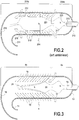
- a combustion chamber 204 of the prior art is illustrated on the figure 2 .
- This combustion chamber 204 comprises an inner wall 211 and an outer wall 212, annular and concentric, extending from a bottom 213, in which the two walls 211 and 212 meet, to an outlet of the combustion gases.
- the combustion chamber 204 may be divided into a primary zone 204a, in which fuel injectors 215, and a dilution zone 204b, downstream of the primary zone 204a, are located.
- the combustion chamber 204 is of the type having a bend 216 in order to limit the axial space requirement.
- This type of combustion chamber is particularly common among centrifugal compressor turbomachines, especially when they are turbine engines such as that illustrated in FIG. figure 1 .
- the walls 211 and 212 of this combustion chamber 204 have three different types of holes, all three allowing the passage of air flow rates on the cold side of the walls 211, 212, outside the combustion chamber 204, the the hot side of the walls 211, 212, inside the combustion chamber 204.
- a first type of holes are the so-called primary holes 217, located in the primary zone 204a and allowing the passage of air for feeding the combustion of the fuel injected by the injectors 215. Downstream of these primary holes 217, the walls 211, 212 also comprise a second type of holes called dilution holes 218, allowing the passage of air for diluting the combustion gases 220 resulting from the combustion of the fuel injected by the injectors 215 with the air entering through the primary holes 217.
- the walls 211, 212 also comprise a third type of holes called cooling holes 219, allowing the passage of air to be used for refilling. stiffen the hot side of each of the walls 211, 212.
- the three types of holes are differentiated in particular by their different sizes.
- the primary holes 217 and especially the dilution holes 218 have substantially larger diameters than the cooling holes 219. Indeed, while the latter, distributed in large numbers on the surface of the walls 211, 212 each have a diameter no greater than 1 mm, the dilution holes 218 have diameters of the order of 5 mm and more.
- the air entering the hot side of the walls 211, 212 through the cooling holes 219 forms a relatively cold air film 221 which remains adjacent to the walls 211, 212 to protect them from
- the air entering through the dilution holes 218 forms jets 222 penetrating deep into the combustion chamber 204 to mix with the combustion gases 220 in the dilution zone 204b.
- a combustion chamber 4 according to one embodiment of the invention is illustrated on the Figure 3 .
- This combustion chamber 4 also comprises an inner wall 11 and an outer wall 12, annular and concentric, extending from a bottom 13, in which the two walls 11 and 12 meet, up to an outlet of the combustion gases.
- the combustion chamber 4 can also be divided into a primary zone 4a, in which fuel injectors 15 are located, and a zone dilution 4b, downstream of the primary zone 4a.
- the inner and outer walls are separated by a maximum radial distance h, and the depth of the primary zone towards the central axis X of the combustion chamber is equal to this distance h.
- the combustion chamber 4 is also of the type having a bend 16 in order to limit its axial size.
- this combustion chamber 4 has only two types of holes allowing the passage of air flow rates on the cold side of the walls 11, 12, outside the chamber.
- combustion chamber 4 at the warm side of the walls 11, 12, inside the combustion chamber 4: primary holes 17 and cooling holes 19.
- the walls 11, 12 have substantially no air passage hole diameter greater than 1 mm.
- the walls 11, 12 may have certain other orifices, such as, for example, holes for the endoscopic inspection of the combustion chamber 4, the cooling holes 19 represent at least 50% of an overall passage area. air through the walls 11,12, and at least 97% in the dilution zone 4b.
- the specific dilution holes of larger diameter being absent, the dilution of the combustion gases 20 is carried out almost exclusively by the air entering the combustion chamber 4 through the cooling holes. 19, the air of the air film 21 adjacent to the walls 11, 12 effectively mixing with the combustion gases 20.
- the cooling holes 19 are oriented so as to pulse on a helical path the air entering the combustion chamber 4 through these cooling holes 19.
- each cooling hole 19 is oriented along an axis which has, relative to the wall 11, 12, an angle ⁇ in the range between 20 ° and 30 °, and a projection on the wall presents an angle ⁇ of approximately 90 ° to the direction of the central axis X.
- the combustion chamber 4 illustrated thus succeeds in diluting the combustion gases in a homogeneous and effective manner, bypassing specific dilution holes of large diameter, and thus avoiding the drawbacks associated therewith.
Landscapes
- Engineering & Computer Science (AREA)
- Chemical & Material Sciences (AREA)
- Combustion & Propulsion (AREA)
- Mechanical Engineering (AREA)
- General Engineering & Computer Science (AREA)
- Turbine Rotor Nozzle Sealing (AREA)
Description
- La présente invention se rapporte au domaine des chambres de combustion pour turbomachines, et en particulier aux parois annulaires de chambres de combustion de turbomachines, comportant un côté froid et un côté chaud.
- Par « turbomachine », on entend, dans le présent contexte, une machine permettant la conversion de l'énergie thermique d'un fluide de travail en énergie mécanique par détente dudit fluide de travail dans une turbine. Dans la description qui suit, les termes "amont" et "aval" sont définis par rapport au sens de circulation normal du fluide de travail dans la turbomachine.
- En particulier, la présente invention se rapporte aux turbomachines dites à combustion interne, dans lequel le fluide de travail de la turbine inclut au moins une partie des produits d'une combustion ayant apporté cette énergie thermique au fluide de travail. Parmi des telles turbomachines, on compte notamment les turbines à gaz, les turboréacteurs, les turbopropulseurs, et les turbomoteurs. Typiquement, des telles turbomachines à combustion interne comprennent, en amont de la turbine, une chambre de combustion dans lequel un carburant est mélangé au fluide de travail, typiquement de l'air, et brûlé. Ainsi, l'énergie chimique contenue dans le carburant est convertie en énergie thermique dans la chambre de combustion, chauffant ainsi le fluide de travail dont l'énergie thermique sera ensuite convertie en énergie mécanique dans la turbine. Typiquement, une telle turbomachine comporte aussi, en amont de la chambre de combustion, un compresseur entraîné par un arbre rotatif commun à au moins un étage de la turbine pour compresser l'air avant la combustion.
- Dans une telle turbomachine, la chambre de combustion comporte typiquement au moins une paroi annulaire munie de trous pour permettre à de l'air circulant du côté froid de la paroi de pénétrer du côté chaud de la paroi. Une telle paroi s'étend, dans le sens de l'écoulement du fluide de travail, entre un fond de la chambre de combustion, où sont normalement situés des injecteurs de carburant, et une sortie de gaz de combustion. La chambre de combustion est typiquement située à l'intérieur d'un carter de générateur de gaz, lequel est en communication avec le compresseur pour recevoir de l'air pressurisé dans ce dernier.
- Dans une telle chambre de combustion, le débit d'air à travers ces trous joue plusieurs rôles. Dans une première zone, dite zone primaire, à proximité du fond de la chambre et donc des injecteurs, la paroi comporte au moins un trou dit primaire et servant principalement à alimenter en air la réaction de combustion avec le carburant injecté par les injecteurs. Toutefois, l'air entrant dans la chambre de combustion à travers des trous situés dans une deuxième zone plus en aval, dite zone de dilution, sert principalement à diluer les gaz de combustion, pour en diminuer ainsi la température en sortie de la chambre de combustion, et donc limiter les contraintes thermiques sur la turbine en aval de la chambre de combustion. Le document
EP 1 811 231 A2 décrit une telle chambre de combustion de turbomachine ayant des parois annulaire avec trois types de trous différents pour le passage d'air à l'intérieur de la chambre de combustion. Des trous primaires alimentent la combustion avec de l'air primaire. L'air passant par des trous de dilution sert à diluer les gaz de combustion résultant de la combustion avec l'air primaire. Des trous de refroidissement permettent le passage de l'air servant à refroidir les parois. - Toutefois, afin d'augmenter l'efficience du cycle thermodynamique de la turbomachine, on a tendance à augmenter de plus en plus la température dans la chambre de combustion. Ceci pose des contraintes thermiques considérables aussi sur les parois de l'enveloppe de la chambre de combustion. Afin de refroidir ces parois, celles-ci peuvent présenter aussi un grand nombre de trous de refroidissement de petit diamètre, normalement non supérieur à 1 mm. L'air entrant dans la chambre de combustion à travers ces trous de refroidissement forme un film relativement froid du côté chaud de chaque paroi, protégeant ainsi le matériau des parois de la chaleur de combustion.
- Dans la zone de dilution des chambres de combustion de l'état de la technique, on a toutefois gardé d'un côté des trous de dilution de grand diamètre, normalement supérieur à 1 mm, pour la dilution des gaz de combustion, et, d'autre part, des trous de refroidissement de petit diamètre, non supérieur à 1 mm, pour le refroidissement des parois de la chambre de combustion, la personne du métier pensant en effet que des jets d'air ne pouvant être produits que par des trous de grand diamètre seraient nécessaires pour pénétrer profondément dans l'écoulement de la chambre de combustion et ainsi obtenir en aval un bon mélange de l'air de dilution avec les gaz de combustion. Toutefois, ceci présente d'autres inconvénients. En particulier, ces jets d'air de dilution peuvent provoquer des hétérogénéités importantes dans la température à l'intérieur de la chambre de combustion. Or, pour des raisons environnementales et d'efficience de combustion, on a intérêt à avoir une distribution la plus homogène possible de la température dans la chambre de combustion. Des pics de température dans celle-ci peuvent provoquer la formation d'oxydes nitreux, tandis que du carburant peut rester sans brûler dans des zones de plus basse température.
- La présente invention se rapporte à une paroi annulaire de chambre de combustion de turbomachine selon la revendication 1, comportant un côté froid et un côté chaud, ladite paroi étant munie d'au moins un trou primaire pour permettre à un premier débit d'air circulant du côté froid de la paroi de pénétrer du côté chaud de la paroi pour alimenter la combustion d'un carburant à l'intérieur de la chambre de combustion, et d'une pluralité de trous de refroidissement, ayant chacun un diamètre non supérieur à 1 mm, pour permettre à un deuxième débit d'air circulant du côté froid de la paroi de pénétrer du côté chaud de la paroi pour refroidir le côté chaud de la paroi.
- Un objet de la présente invention est celui d'homogénéiser la distribution de température dans la chambre de combustion, tout en augmentant l'efficience du cycle thermodynamique de la turbomachine. Pour cela, selon l'invention, la pluralité de trous de refroidissement est aussi apte à assurer la dilution de gaz de combustion issus de ladite combustion par le débit d'air pénétrant du côté chaud de la paroi à travers les trous de refroidissement. Contrairement au préjugé des personnes du métier, on a constaté que l'apport d'air à travers de tels orifices de petit diamètre suffit à assurer non seulement le refroidissement des parois de la chambre de combustion, mais aussi un brassage efficace des gaz de combustion avec l'air apporté par ces orifices de petit diamètre, résultant en une dilution efficace des gaz de combustion.
- En particulier, selon un deuxième aspect de l'invention, dans une telle chambre de combustion, lesdits trous de refroidissement peuvent représenter au moins 50% d'une surface globale de passage d'air à travers la paroi, et plus spécifiquement au moins 97% d'une surface globale de passage d'air à travers la paroi en aval dudit au moins un trou primaire. On peut ainsi largement se passer d'orifices de grand diamètre pour la dilution des gaz de combustion, ce qui non seulement aide à éviter les hétérogénéités dans l'écoulement dans la chambre de combustion, mais peut aussi faciliter la fabrication de la zone de dilution de la chambre de combustion.
- Selon un troisième aspect, afin d'améliorer le brassage des gaz de combustion avec l'air apporté par les trous de refroidissement, chaque trou d'une pluralité desdits trous de refroidissement est orienté suivant un axe dont une projection sur la paroi présente un angle θ au moins égal à 45° par rapport à la direction d'un axe central de la paroi. En particulier, ledit angle θ pourrait être entre 85° et 95°. Ainsi, l'air injecté dans la chambre de combustion à travers les trous de refroidissement suivra un écoulement hélicoïdal, prolongeant son séjour dans la chambre de combustion et épaississant le film d'air relativement froid adjacent au côté chaud de la paroi, ce qui bénéficie non seulement au refroidissement de la paroi, mais aussi au brassage des gaz de combustion avec l'air de ce film plus épais.
- Selon un quatrième aspect, aussi afin d'améliorer le brassage des gaz de combustion avec l'air introduit par les trous de refroidissement, chaque trou d'une pluralité desdits trous de refroidissement est orienté suivant un axe présentant, par rapport à la paroi, un angle β non supérieur à 45°, et de préférence non supérieur à 30°. On assure ainsi la stabilité du film d'air relativement froid adjacent au côté chaud de la paroi.
- Toutefois, selon un cinquième aspect, et aussi afin de stabiliser le film d'air froid, ledit angle β est au moins égal à 15°, et de préférence au moins égal à 20°.
- La présente invention se rapporte aussi à une chambre de combustion de turbomachine comportant une paroi intérieure et une paroi extérieure concentriques, ladite paroi intérieure et/ou ladite paroi extérieure étant une paroi annulaire suivant une quelconque des revendications 1 à 7. La présente invention se rapporte aussi à une turbomachine, telle qu'une turbine à gaz, turboréacteur, turbopropulseur ou turbomoteur, en particulier pour une application aéronautique, comportant une chambre de combustion avec au moins une paroi annulaire suivant l'une quelconque des revendications 1 à 7. La présente invention se rapporte aussi à un procédé de dilution des gaz de combustion dans une chambre de combustion de turbomachine, turbomachine selon la revendication 10, ladite chambre de combustion comportant au moins une paroi annulaire avec un côté froid et un côté chaud, et étant munie d'au moins un trou primaire pour permettre à un premier débit d'air circulant du côté froid de la paroi de pénétrer du côté chaud de la paroi pour alimenter la combustion d'un carburant à l'intérieur de la chambre de combustion, et d'une pluralité de trous de refroidissement, ayant chacun un diamètre non supérieur à 1 mm, pour permettre à un deuxième débit d'air circulant du côté froid de la paroi de pénétrer du côté chaud de la paroi pour refroidir le côté chaud de la paroi, dans lequel procédé le débit d'air pénétrant du côté chaud de la paroi assure aussi la dilution des qaz de combustion.
- L'invention sera bien comprise et ses avantages apparaîtront mieux, à la lecture de la description détaillée qui suit, d'un mode de réalisation représenté à titre d'exemple non limitatif. La description se réfère aux dessins annexés sur lesquels :
- la
figure 1 est une coupe longitudinale schématique d'une turbomachine ; - la
figure 2 est une coupe longitudinale schématique d'une chambre de combustion de l'art antérieur ; - la
figure 3 est une coupe longitudinale schématique d'une chambre de combustion suivant un premier mode de réalisation de l'invention ; - la
figure 4A est une vue de détail d'une paroi de la chambre de combustion de lafigure 3 , en projection cylindrique ; et - la
figure 4B est une vue de détail de la même paroi, en coupe transversale suivant la ligne IVB-IVB. - Une turbomachine, plus spécifiquement sous forme d'un turbomoteur 1, est illustrée schématiquement à titre explicatif sur la
figure 1 . Ce turbomoteur 1 comporte, dans le sens d'écoulement d'un fluide de travail, un compresseur centrifuge 3, une chambre de combustion annulaire 4, une première turbine axiale 5, et une deuxième turbine axiale 6. En outre, le turbomoteur 1 comprend aussi un premier arbre rotatif 7 et un deuxième arbre rotatif 8 coaxial au premier arbre rotatif 7. - Le deuxième arbre rotatif 8 relie le compresseur centrifuge 3 à la première turbine axiale 5, de manière à ce que la détente du fluide de travail dans cette première turbine axiale 5 en aval de la chambre de combustion 4 serve à actionner le compresseur 3 en amont de la chambre de combustion 4. Le premier arbre rotatif 7 relie la deuxième turbine axiale 6 à une sortie de puissance 9 positionnée en aval et/ou en amont de la machine, de telle manière que la détente subséquente du fluide de travail dans la deuxième turbine axiale 6 en aval de la première turbine axiale 5 serve à actionner la sortie de puissance 9.
- Ainsi, la compression du fluide de travail dans le compresseurs centrifuge 3, suivie par un réchauffement du fluide de travail dans la chambre de combustion 4, et sa détente dans la deuxième turbine axiale 6 permettent la conversion d'une partie de l'énergie thermique introduite par la combustion dans la chambre de combustion 4 en travail mécanique extrait par la sortie de puissance 9. Dans la turbomachine illustrée, le fluide moteur est de l'air, auquel on ajoute et dans lequel on brûle un carburant dans la chambre de combustion 4, carburant tel que, par exemple, un hydrocarbure.
- Une chambre de combustion 204 de l'art antérieur est illustrée sur la
figure 2 . Cette chambre de combustion 204 comporte une paroi intérieure 211 et une paroi extérieure 212, annulaires et concentriques, s'étendant d'un fond 213, dans lequel les deux parois 211 et 212 se rejoignent, jusqu'à une sortie des gaz de combustion. La chambre de combustion 204 peut être divisée en une zone primaire 204a, dans laquelle sont situés des injecteurs de carburant 215, et une zone de dilution 204b, en aval de la zone primaire 204a. Dans l'exemple illustré, la chambre de combustion 204 est du type présentant un coude 216 afin de limiter l'encombrement axial. Ce type de chambres de combustion est particulièrement courant parmi les turbomachines à compresseur centrifuges, surtout quand elles sont des turbomoteurs comme celui illustré sur lafigure 1 . - Les parois 211 et 212 de cette chambre de combustion 204 présentent trois types de trous différents, permettant tous les trois le passage de débits d'air du côté froid des parois 211, 212, à l'extérieur de la chambre de combustion 204, au côté chaud des parois 211, 212, à l'intérieur de la chambre des combustion 204. Un premier type de trous sont les trous dits primaires 217, situés dans la zone primaire 204a et permettant le passage d'air servant à alimenter la combustion du carburant injecté par les injecteurs 215. En aval de ces trous primaires 217, les parois 211, 212 comportent aussi un deuxième type de trous dits trous de dilution 218, permettant le passage d'air servant à diluer les gaz de combustion 220 résultant de la combustion du carburant injecté par les injecteurs 215 avec l'air entrant par les trous primaires 217. Les parois 211, 212 comportent aussi un troisième type de trous dits trous de refroidissement 219, permettant le passage d'air servant à refroidir le côté chaud de chacune des parois 211, 212. Les trois types de trous se différentient notamment par leurs tailles différentes. Ainsi, les trous primaires 217 et surtout les trous de dilution 218 présentent des diamètres sensiblement plus grands que les trous de refroidissement 219. En effet, tandis que ces derniers, distribués en grand nombre sur la surface des parois 211, 212 ont chacun un diamètre non supérieur à 1 mm, les trous de dilution 218 ont des diamètres de l'ordre de 5 mm et plus. Ainsi, quand la turbomachine est en fonctionnement, l'air pénétrant du côté chaud des parois 211, 212 à travers les trous de refroidissement 219 forme un film d'air 221 relativement froid qui reste adjacent aux parois 211, 212 afin de les protéger de la chaleur des gaz de combustion 220, l'air pénétrant à travers les trous de dilution 218 forme des jets 222 pénétrant profondément dans la chambre de combustion 204 pour se mélanger avec les gaz de combustion 220 dans la zone de dilution 204b.
- Une chambre de combustion 4 suivant un mode de réalisation de l'invention est illustrée sur la
Figure 3 . Cette chambre de combustion 4 comporte aussi une paroi intérieure 11 et une paroi extérieure 12, annulaires et concentriques, s'étendant d'un fond 13, dans lequel les deux parois 11 et 12 se rejoignent, jusqu'à une sortie des gaz de combustion. La chambre de combustion 4 peut aussi être divisée en une zone primaire 4a, dans laquelle sont situés des injecteurs de carburant 15, et une zone de dilution 4b, en aval de la zone primaire 4a. Dans le mode de réalisation illustré, les parois intérieure et extérieure sont séparées par une distance radiale maximale h, et la profondeur de la zone primaire en direction de l'axe central X de la chambre de combustion est égale à cette distance h. Dans l'exemple illustré, la chambre de combustion 4 est aussi du type présentant un coude 16 afin de limiter son encombrement axial. - Toutefois, contrairement à la chambre de combustion 204 de l'art antérieur, cette chambre de combustion 4 ne présente que deux types de trous permettant le passage de débits d'air du côté froid des parois 11, 12, à l'extérieur de la chambre de combustion 4, au côté chaud des parois 11, 12, à l'intérieur de la chambre de combustion 4 : des trous primaires 17 et des trous de refroidissement 19. Ainsi, en aval desdits trous primaires 17, et en particulier dans la zone de dilution 4b, les parois 11, 12 ne présentent pratiquement pas de trou de passage d'air de diamètre supérieur à 1 mm. Bien que les parois 11,12 puissent présenter certains autres orifices, comme, par exemple des trous pour l'inspection endoscopique de la chambre de combustion 4, les trous de refroidissement 19 représentent au moins 50% d'une surface globale de passage d'air à travers les parois 11,12, et au moins 97% dans la zone de dilution 4b.
- Dans cette chambre de combustion 4, les trous de dilution spécifiques de plus grand diamètre étant absents, la dilution des gaz de combustion 20 s'effectue de manière pratiquement exclusive par l'air pénétrant dans la chambre de combustion 4 à travers les trous de refroidissement 19, l'air du film d'air 21 adjacent aux parois 11, 12 se mélangeant effectivement aux gaz de combustion 20. Afin de faciliter ce mélange, dans le mode de réalisation illustré les trous de refroidissement 19 sont orientés de manière à impulser sur une trajectoire hélicoïdale l'air pénétrant dans la chambre de combustion 4 à travers ces trous de refroidissement 19. Ainsi, comme illustré sur les
figures 4A et 4B , dans ce mode de réalisation chaque trou de refroidissement 19 est orienté suivant un axe qui présente, par rapport à la paroi 11,12, un angle β dans la plage comprise entre 20° et 30°, et dont une projection sur la paroi présente un angle θ d'approximativement 90° par rapport à la direction de l'axe central X. La chambre de combustion 4 illustrée parvient ainsi à diluer les gaz de combustion 20 de manière homogène et effective, en se passant de trous de dilution spécifiques de grand diamètre, et évitant ainsi les inconvénients liés à ceux-ci.
Claims (10)
- Paroi annulaire (11,12) de chambre de combustion (4) de turbomachine, ladite paroi (11,12) ayant un côté froid et un côté chaud et étant munie d'au moins un trou primaire (17) pour permettre à un premier débit d'air circulant du côté froid de la paroi (11,12) de pénétrer du côté chaud de la paroi (11,12) pour alimenter la combustion d'un carburant à l'intérieur de la chambre de combustion (4), et d'une pluralité de trous de refroidissement (19), ayant chacun un diamètre non supérieur à 1 mm, pour permettre à un deuxième débit d'air circulant du côté froid de la paroi (11,12) de pénétrer du côté chaud de la paroi (11,12) pour refroidir le côté chaud de la paroi (11,12), ladite pluralité de trous de refroidissement (19) étant aussi apte à assurer la dilution de gaz de combustion (20) issus de ladite combustion par le débit d'air pénétrant du côté chaud de la paroi (11,12) à travers les trous de refroidissement (19).
- Paroi annulaire (11,12) de chambre de combustion (4) de turbomachine suivant la revendication 1, dans laquelle lesdits trous de refroidissement (19) représentent au moins 50% d'une surface globale de passage d'air à travers la paroi (11,12).
- Paroi annulaire (11,12) de chambre de combustion (4) de turbomachine suivant l'une quelconque des revendications 1 ou 2, dans laquelle lesdits trous de refroidissement (19) représentent au moins 97% d'une surface globale de passage d'air à travers la paroi (11,12) en aval dudit au moins un trou primaire (17).
- Paroi annulaire (11,12) de chambre de combustion (4) de turbomachine suivant l'une quelconque des revendications 1 à 3, dans laquelle chaque trou d'une pluralité desdits trous de refroidissement (19) est orienté suivant un axe dont une projection sur la paroi (11,12) présente un angle θ au moins égal à 45° par rapport à la direction d'un axe central (X) de la paroi (11,12).
- Paroi annulaire (11,12) de chambre de combustion (4) de turbomachine suivant la revendication 4, dans laquelle ledit angle θ est entre 85° et 95°.
- Paroi annulaire (11,12) de chambre de combustion (4) de turbomachine suivant l'une quelconque des revendications précédentes, dans laquelle chaque trou d'une pluralité desdits trous de refroidissement (19) est orienté suivant un axe présentant, par rapport à la paroi (11,12), un angle β non supérieur à 45°, et de préférence non supérieur à 30°.
- Paroi annulaire (11,12) de chambre de combustion (4) de turbomachine suivant la revendication 6, dans laquelle ledit angle β est au moins égal à 15°, et de préférence au moins égal à 20°.
- Chambre de combustion (4) de turbomachine comportant une paroi intérieure (11) et une paroi extérieure (12) concentriques, ladite paroi intérieure (11) et/ou ladite paroi extérieure (12) étant une paroi annulaire suivant une quelconque des revendications 1 à 7.
- Turbomachine (1) comportant une chambre de combustion (4) avec au moins une paroi annulaire (11,12) suivant l'une quelconque des revendications 1 à 7.
- Procédé de dilution des gaz de combustion (20) dans une chambre de combustion (4) de turbomachine, ladite chambre de combustion (4) comportant au moins une paroi annulaire (11,12) avec un côté froid et un côté chaud, et étant munie d'au moins un trou primaire (17) pour permettre à un premier débit d'air circulant du côté froid de la paroi de pénétrer du côté chaud de la paroi (11,12) pour alimenter la combustion d'un carburant à l'intérieur de la chambre de combustion (4), et d'une pluralité de trous de refroidissement (19), ayant chacun un diamètre non supérieur à 1 mm, pour permettre à un deuxième débit d'air circulant du côté froid de la paroi (11,12) de pénétrer du côté chaud de la paroi (11,12) pour refroidir le côté chaud de la paroi (11,12), dans lequel procédé le débit d'air pénétrant du côté chaud de la paroi (11,12) assure aussi la dilution des gaz de combustion (20).
Priority Applications (1)
| Application Number | Priority Date | Filing Date | Title |
|---|---|---|---|
| PL12756782T PL2748532T3 (pl) | 2011-08-26 | 2012-08-22 | Pierścieniowa ścianka komory spalania maszyny wirowej |
Applications Claiming Priority (2)
| Application Number | Priority Date | Filing Date | Title |
|---|---|---|---|
| FR1157574A FR2979416B1 (fr) | 2011-08-26 | 2011-08-26 | Paroi de chambre de combustion |
| PCT/FR2012/051917 WO2013030492A1 (fr) | 2011-08-26 | 2012-08-22 | Paroi de chambre de combustion |
Publications (2)
| Publication Number | Publication Date |
|---|---|
| EP2748532A1 EP2748532A1 (fr) | 2014-07-02 |
| EP2748532B1 true EP2748532B1 (fr) | 2017-08-09 |
Family
ID=46829816
Family Applications (1)
| Application Number | Title | Priority Date | Filing Date |
|---|---|---|---|
| EP12756782.4A Active EP2748532B1 (fr) | 2011-08-26 | 2012-08-22 | Paroi annulaire de chambre de combustion de turbomachine |
Country Status (11)
| Country | Link |
|---|---|
| US (1) | US10156358B2 (fr) |
| EP (1) | EP2748532B1 (fr) |
| JP (1) | JP6012733B2 (fr) |
| KR (1) | KR101971305B1 (fr) |
| CN (1) | CN103765108B (fr) |
| CA (1) | CA2843690C (fr) |
| ES (1) | ES2640795T3 (fr) |
| FR (1) | FR2979416B1 (fr) |
| PL (1) | PL2748532T3 (fr) |
| RU (1) | RU2614305C2 (fr) |
| WO (1) | WO2013030492A1 (fr) |
Families Citing this family (7)
| Publication number | Priority date | Publication date | Assignee | Title |
|---|---|---|---|---|
| FR3021097B1 (fr) * | 2014-05-15 | 2020-05-08 | Safran Power Units | Chambre de combustion a flux inverse comprenant une paroi de coude optimisee |
| CN108290198A (zh) * | 2015-01-09 | 2018-07-17 | 哈佛大学校董委员会 | 以工程化图案具有扭曲的投影狭槽以提供npr特性和改善的应力性能的拉胀结构 |
| RU2017126597A (ru) * | 2015-01-09 | 2019-02-11 | Президент Энд Феллоус Оф Харвард Колледж | Ауксетическая структура с наклонными прорезями в конфигурациях, разработанных для обеспечения заданного поведения с отрицательным коэффициентом Пуассона и улучшенной характеристики охлаждения |
| FR3038364B1 (fr) * | 2015-07-01 | 2020-01-03 | Safran Helicopter Engines | Paroi de chambre de combustion |
| EP3159609A1 (fr) * | 2015-10-21 | 2017-04-26 | Siemens Aktiengesellschaft | Chambre de combustion pour turbine à gaz |
| FR3061948B1 (fr) * | 2017-01-19 | 2021-01-22 | Safran Helicopter Engines | Chambre de combustion de turbomachine a haute permeabilite |
| CN109668173B (zh) * | 2019-01-14 | 2019-11-26 | 西安增材制造国家研究院有限公司 | 一种蒸发管式紧凑型燃烧室 |
Family Cites Families (17)
| Publication number | Priority date | Publication date | Assignee | Title |
|---|---|---|---|---|
| FR2668246B1 (fr) * | 1990-10-17 | 1994-12-09 | Snecma | Chambre de combustion munie d'un dispositif de refroidissement de sa paroi. |
| US5233828A (en) * | 1990-11-15 | 1993-08-10 | General Electric Company | Combustor liner with circumferentially angled film cooling holes |
| CA2048726A1 (fr) * | 1990-11-15 | 1992-05-16 | Phillip D. Napoli | Chemise de chambre de combustion |
| CA2056592A1 (fr) * | 1990-12-21 | 1992-06-22 | Phillip D. Napoli | Chemise de chambre de combustion a refroidissement par gaine d'air a trous multiples avec demarreur a gaine d'air rainuree |
| US5261223A (en) * | 1992-10-07 | 1993-11-16 | General Electric Company | Multi-hole film cooled combustor liner with rectangular film restarting holes |
| FR2733582B1 (fr) * | 1995-04-26 | 1997-06-06 | Snecma | Chambre de combustion comportant une multiperforation d'inclinaison axiale et tangentielle variable |
| RU2173819C2 (ru) * | 1999-10-25 | 2001-09-20 | Центральный институт авиационного моторостроения им. П.И. Баранова | Камера сгорания газотурбинного двигателя |
| US6408629B1 (en) * | 2000-10-03 | 2002-06-25 | General Electric Company | Combustor liner having preferentially angled cooling holes |
| FR2856468B1 (fr) * | 2003-06-17 | 2007-11-23 | Snecma Moteurs | Chambre de combustion annulaire de turbomachine |
| US20060037323A1 (en) * | 2004-08-20 | 2006-02-23 | Honeywell International Inc., | Film effectiveness enhancement using tangential effusion |
| US7614235B2 (en) * | 2005-03-01 | 2009-11-10 | United Technologies Corporation | Combustor cooling hole pattern |
| US7631502B2 (en) * | 2005-12-14 | 2009-12-15 | United Technologies Corporation | Local cooling hole pattern |
| US7546737B2 (en) * | 2006-01-24 | 2009-06-16 | Honeywell International Inc. | Segmented effusion cooled gas turbine engine combustor |
| FR2899315B1 (fr) * | 2006-03-30 | 2012-09-28 | Snecma | Configuration d'ouvertures de dilution dans une paroi de chambre de combustion de turbomachine |
| US7942006B2 (en) | 2007-03-26 | 2011-05-17 | Honeywell International Inc. | Combustors and combustion systems for gas turbine engines |
| US20090199563A1 (en) * | 2008-02-07 | 2009-08-13 | Hamilton Sundstrand Corporation | Scalable pyrospin combustor |
| US9897320B2 (en) * | 2009-07-30 | 2018-02-20 | Honeywell International Inc. | Effusion cooled dual wall gas turbine combustors |
-
2011
- 2011-08-26 FR FR1157574A patent/FR2979416B1/fr active Active
-
2012
- 2012-08-22 RU RU2014111483A patent/RU2614305C2/ru active
- 2012-08-22 WO PCT/FR2012/051917 patent/WO2013030492A1/fr not_active Ceased
- 2012-08-22 PL PL12756782T patent/PL2748532T3/pl unknown
- 2012-08-22 US US14/239,977 patent/US10156358B2/en active Active
- 2012-08-22 CN CN201280040714.4A patent/CN103765108B/zh active Active
- 2012-08-22 ES ES12756782.4T patent/ES2640795T3/es active Active
- 2012-08-22 CA CA2843690A patent/CA2843690C/fr not_active Expired - Fee Related
- 2012-08-22 JP JP2014526534A patent/JP6012733B2/ja not_active Expired - Fee Related
- 2012-08-22 EP EP12756782.4A patent/EP2748532B1/fr active Active
- 2012-08-22 KR KR1020147004607A patent/KR101971305B1/ko not_active Expired - Fee Related
Non-Patent Citations (1)
| Title |
|---|
| None * |
Also Published As
| Publication number | Publication date |
|---|---|
| US10156358B2 (en) | 2018-12-18 |
| PL2748532T3 (pl) | 2017-11-30 |
| RU2614305C2 (ru) | 2017-03-24 |
| JP6012733B2 (ja) | 2016-10-25 |
| ES2640795T3 (es) | 2017-11-06 |
| CN103765108B (zh) | 2016-08-24 |
| CA2843690C (fr) | 2019-08-27 |
| US20140208763A1 (en) | 2014-07-31 |
| KR101971305B1 (ko) | 2019-04-22 |
| WO2013030492A1 (fr) | 2013-03-07 |
| JP2014525557A (ja) | 2014-09-29 |
| CN103765108A (zh) | 2014-04-30 |
| RU2014111483A (ru) | 2015-10-10 |
| KR20140051969A (ko) | 2014-05-02 |
| EP2748532A1 (fr) | 2014-07-02 |
| FR2979416B1 (fr) | 2013-09-20 |
| FR2979416A1 (fr) | 2013-03-01 |
| CA2843690A1 (fr) | 2013-03-07 |
Similar Documents
| Publication | Publication Date | Title |
|---|---|---|
| CA2843690C (fr) | Paroi de chambre de combustion | |
| EP3267111B1 (fr) | Paroi annulaire de chambre de combustion à refroidissement amelioré au niveau des trous primaires et/ou de dilution | |
| EP0913645B1 (fr) | Chambre de combustion pour turbomachine | |
| US9759426B2 (en) | Combustor nozzles in gas turbine engines | |
| FR2965605A1 (fr) | Turbomachine incluant un element de tube de melange comportant un generateur de tourbillons | |
| FR2635577A1 (fr) | Chambre de combustion pour moteur a turbine a gaz | |
| EP1503061A1 (fr) | Procédé de refroidissement, par air refroidi en partie dans un échangeur externe, des parties chaudes d'un turboréacteur, et turboréacteur ainsi refroidi. | |
| FR3001790A1 (fr) | Chambre de combustion a volume variable avec systeme d'injection de combustible en amont des injecteurs | |
| EP2053311B1 (fr) | Parois de chambre de combustion à dilution et refroidissement optimisés, chambre de combustion et turbomachine en étant munies | |
| EP2462383B1 (fr) | Chambre de combustion de turbomachine comprenant des orifices d'entrée d'air améliorés | |
| FR2531748A1 (fr) | Chemise de chambre a combustion a courant d'air de refroidissement a double fonction | |
| US10443402B2 (en) | Thermal shielding in a gas turbine | |
| US20180051570A1 (en) | Gas turbine blade | |
| FR2865525A1 (fr) | Methode de formation d'une zone de passage pour l'alimentation en carburant dans la tubulure d'un injecteur pour turbine d'un reacteur | |
| FR2966505A1 (fr) | Systeme et procede pour refroidir une tuyere | |
| EP2071240B1 (fr) | Chambre de combustion de turbomachine | |
| FR2976970A1 (fr) | Systeme de turbine a vapeur et procede de refroidissement d'espaces entre roues d'une turbine a vapeur | |
| FR3015010A1 (fr) | Paroi annulaire pour chambre de combustion de turbomachine comprenant des orifices de refroidissement a effet contra-rotatif | |
| FR3061948A1 (fr) | Chambre de combustion de turbomachine a haute permeabilite | |
| FR2966517A1 (fr) | Systeme et procede pour refroidir une tuyere | |
| US20160169517A1 (en) | Counter-swirl doublet combustor with plunged holes | |
| US10119470B2 (en) | Shaft assembly of a gas turbine engine and method of controlling flow therein | |
| FR2980553A1 (fr) | Chambre de combustion de turbomachine | |
| FR3098569A1 (fr) | Paroi annulaire pour chambre de combustion de turbomachine comprenant des trous primaires, des trous de dilution et des orifices de refroidissement inclines | |
| FR2968034A1 (fr) | Systeme de purge pour machine tournante |
Legal Events
| Date | Code | Title | Description |
|---|---|---|---|
| PUAI | Public reference made under article 153(3) epc to a published international application that has entered the european phase |
Free format text: ORIGINAL CODE: 0009012 |
|
| 17P | Request for examination filed |
Effective date: 20140318 |
|
| AK | Designated contracting states |
Kind code of ref document: A1 Designated state(s): AL AT BE BG CH CY CZ DE DK EE ES FI FR GB GR HR HU IE IS IT LI LT LU LV MC MK MT NL NO PL PT RO RS SE SI SK SM TR |
|
| DAX | Request for extension of the european patent (deleted) | ||
| 17Q | First examination report despatched |
Effective date: 20160408 |
|
| RAP1 | Party data changed (applicant data changed or rights of an application transferred) |
Owner name: SAFRAN HELICOPTER ENGINES |
|
| GRAP | Despatch of communication of intention to grant a patent |
Free format text: ORIGINAL CODE: EPIDOSNIGR1 |
|
| INTG | Intention to grant announced |
Effective date: 20170328 |
|
| GRAS | Grant fee paid |
Free format text: ORIGINAL CODE: EPIDOSNIGR3 |
|
| GRAA | (expected) grant |
Free format text: ORIGINAL CODE: 0009210 |
|
| AK | Designated contracting states |
Kind code of ref document: B1 Designated state(s): AL AT BE BG CH CY CZ DE DK EE ES FI FR GB GR HR HU IE IS IT LI LT LU LV MC MK MT NL NO PL PT RO RS SE SI SK SM TR |
|
| REG | Reference to a national code |
Ref country code: GB Ref legal event code: FG4D Free format text: NOT ENGLISH |
|
| REG | Reference to a national code |
Ref country code: CH Ref legal event code: EP Ref country code: AT Ref legal event code: REF Ref document number: 917267 Country of ref document: AT Kind code of ref document: T Effective date: 20170815 |
|
| REG | Reference to a national code |
Ref country code: FR Ref legal event code: PLFP Year of fee payment: 6 |
|
| REG | Reference to a national code |
Ref country code: IE Ref legal event code: FG4D Free format text: LANGUAGE OF EP DOCUMENT: FRENCH |
|
| REG | Reference to a national code |
Ref country code: DE Ref legal event code: R096 Ref document number: 602012035682 Country of ref document: DE |
|
| REG | Reference to a national code |
Ref country code: SE Ref legal event code: TRGR |
|
| REG | Reference to a national code |
Ref country code: ES Ref legal event code: FG2A Ref document number: 2640795 Country of ref document: ES Kind code of ref document: T3 Effective date: 20171106 |
|
| REG | Reference to a national code |
Ref country code: NL Ref legal event code: MP Effective date: 20170809 |
|
| REG | Reference to a national code |
Ref country code: LT Ref legal event code: MG4D |
|
| REG | Reference to a national code |
Ref country code: AT Ref legal event code: MK05 Ref document number: 917267 Country of ref document: AT Kind code of ref document: T Effective date: 20170809 |
|
| PG25 | Lapsed in a contracting state [announced via postgrant information from national office to epo] |
Ref country code: AT Free format text: LAPSE BECAUSE OF FAILURE TO SUBMIT A TRANSLATION OF THE DESCRIPTION OR TO PAY THE FEE WITHIN THE PRESCRIBED TIME-LIMIT Effective date: 20170809 Ref country code: NL Free format text: LAPSE BECAUSE OF FAILURE TO SUBMIT A TRANSLATION OF THE DESCRIPTION OR TO PAY THE FEE WITHIN THE PRESCRIBED TIME-LIMIT Effective date: 20170809 Ref country code: FI Free format text: LAPSE BECAUSE OF FAILURE TO SUBMIT A TRANSLATION OF THE DESCRIPTION OR TO PAY THE FEE WITHIN THE PRESCRIBED TIME-LIMIT Effective date: 20170809 Ref country code: NO Free format text: LAPSE BECAUSE OF FAILURE TO SUBMIT A TRANSLATION OF THE DESCRIPTION OR TO PAY THE FEE WITHIN THE PRESCRIBED TIME-LIMIT Effective date: 20171109 Ref country code: HR Free format text: LAPSE BECAUSE OF FAILURE TO SUBMIT A TRANSLATION OF THE DESCRIPTION OR TO PAY THE FEE WITHIN THE PRESCRIBED TIME-LIMIT Effective date: 20170809 Ref country code: LT Free format text: LAPSE BECAUSE OF FAILURE TO SUBMIT A TRANSLATION OF THE DESCRIPTION OR TO PAY THE FEE WITHIN THE PRESCRIBED TIME-LIMIT Effective date: 20170809 |
|
| PG25 | Lapsed in a contracting state [announced via postgrant information from national office to epo] |
Ref country code: GR Free format text: LAPSE BECAUSE OF FAILURE TO SUBMIT A TRANSLATION OF THE DESCRIPTION OR TO PAY THE FEE WITHIN THE PRESCRIBED TIME-LIMIT Effective date: 20171110 Ref country code: RS Free format text: LAPSE BECAUSE OF FAILURE TO SUBMIT A TRANSLATION OF THE DESCRIPTION OR TO PAY THE FEE WITHIN THE PRESCRIBED TIME-LIMIT Effective date: 20170809 Ref country code: LV Free format text: LAPSE BECAUSE OF FAILURE TO SUBMIT A TRANSLATION OF THE DESCRIPTION OR TO PAY THE FEE WITHIN THE PRESCRIBED TIME-LIMIT Effective date: 20170809 Ref country code: IS Free format text: LAPSE BECAUSE OF FAILURE TO SUBMIT A TRANSLATION OF THE DESCRIPTION OR TO PAY THE FEE WITHIN THE PRESCRIBED TIME-LIMIT Effective date: 20171209 Ref country code: BG Free format text: LAPSE BECAUSE OF FAILURE TO SUBMIT A TRANSLATION OF THE DESCRIPTION OR TO PAY THE FEE WITHIN THE PRESCRIBED TIME-LIMIT Effective date: 20171109 |
|
| REG | Reference to a national code |
Ref country code: CH Ref legal event code: PL |
|
| PG25 | Lapsed in a contracting state [announced via postgrant information from national office to epo] |
Ref country code: RO Free format text: LAPSE BECAUSE OF FAILURE TO SUBMIT A TRANSLATION OF THE DESCRIPTION OR TO PAY THE FEE WITHIN THE PRESCRIBED TIME-LIMIT Effective date: 20170809 Ref country code: DK Free format text: LAPSE BECAUSE OF FAILURE TO SUBMIT A TRANSLATION OF THE DESCRIPTION OR TO PAY THE FEE WITHIN THE PRESCRIBED TIME-LIMIT Effective date: 20170809 Ref country code: LI Free format text: LAPSE BECAUSE OF NON-PAYMENT OF DUE FEES Effective date: 20170831 Ref country code: CH Free format text: LAPSE BECAUSE OF NON-PAYMENT OF DUE FEES Effective date: 20170831 |
|
| REG | Reference to a national code |
Ref country code: DE Ref legal event code: R097 Ref document number: 602012035682 Country of ref document: DE |
|
| REG | Reference to a national code |
Ref country code: IE Ref legal event code: MM4A |
|
| PG25 | Lapsed in a contracting state [announced via postgrant information from national office to epo] |
Ref country code: MC Free format text: LAPSE BECAUSE OF FAILURE TO SUBMIT A TRANSLATION OF THE DESCRIPTION OR TO PAY THE FEE WITHIN THE PRESCRIBED TIME-LIMIT Effective date: 20170809 Ref country code: SM Free format text: LAPSE BECAUSE OF FAILURE TO SUBMIT A TRANSLATION OF THE DESCRIPTION OR TO PAY THE FEE WITHIN THE PRESCRIBED TIME-LIMIT Effective date: 20170809 Ref country code: SK Free format text: LAPSE BECAUSE OF FAILURE TO SUBMIT A TRANSLATION OF THE DESCRIPTION OR TO PAY THE FEE WITHIN THE PRESCRIBED TIME-LIMIT Effective date: 20170809 Ref country code: EE Free format text: LAPSE BECAUSE OF FAILURE TO SUBMIT A TRANSLATION OF THE DESCRIPTION OR TO PAY THE FEE WITHIN THE PRESCRIBED TIME-LIMIT Effective date: 20170809 |
|
| REG | Reference to a national code |
Ref country code: BE Ref legal event code: MM Effective date: 20170831 |
|
| PLBE | No opposition filed within time limit |
Free format text: ORIGINAL CODE: 0009261 |
|
| STAA | Information on the status of an ep patent application or granted ep patent |
Free format text: STATUS: NO OPPOSITION FILED WITHIN TIME LIMIT |
|
| PG25 | Lapsed in a contracting state [announced via postgrant information from national office to epo] |
Ref country code: LU Free format text: LAPSE BECAUSE OF NON-PAYMENT OF DUE FEES Effective date: 20170822 |
|
| 26N | No opposition filed |
Effective date: 20180511 |
|
| REG | Reference to a national code |
Ref country code: FR Ref legal event code: PLFP Year of fee payment: 7 |
|
| PG25 | Lapsed in a contracting state [announced via postgrant information from national office to epo] |
Ref country code: IE Free format text: LAPSE BECAUSE OF NON-PAYMENT OF DUE FEES Effective date: 20170822 |
|
| PG25 | Lapsed in a contracting state [announced via postgrant information from national office to epo] |
Ref country code: SI Free format text: LAPSE BECAUSE OF FAILURE TO SUBMIT A TRANSLATION OF THE DESCRIPTION OR TO PAY THE FEE WITHIN THE PRESCRIBED TIME-LIMIT Effective date: 20170809 Ref country code: BE Free format text: LAPSE BECAUSE OF NON-PAYMENT OF DUE FEES Effective date: 20170831 |
|
| PG25 | Lapsed in a contracting state [announced via postgrant information from national office to epo] |
Ref country code: MT Free format text: LAPSE BECAUSE OF FAILURE TO SUBMIT A TRANSLATION OF THE DESCRIPTION OR TO PAY THE FEE WITHIN THE PRESCRIBED TIME-LIMIT Effective date: 20170809 |
|
| PG25 | Lapsed in a contracting state [announced via postgrant information from national office to epo] |
Ref country code: HU Free format text: LAPSE BECAUSE OF FAILURE TO SUBMIT A TRANSLATION OF THE DESCRIPTION OR TO PAY THE FEE WITHIN THE PRESCRIBED TIME-LIMIT; INVALID AB INITIO Effective date: 20120822 |
|
| PG25 | Lapsed in a contracting state [announced via postgrant information from national office to epo] |
Ref country code: CY Free format text: LAPSE BECAUSE OF NON-PAYMENT OF DUE FEES Effective date: 20170809 |
|
| PG25 | Lapsed in a contracting state [announced via postgrant information from national office to epo] |
Ref country code: MK Free format text: LAPSE BECAUSE OF FAILURE TO SUBMIT A TRANSLATION OF THE DESCRIPTION OR TO PAY THE FEE WITHIN THE PRESCRIBED TIME-LIMIT Effective date: 20170809 |
|
| PG25 | Lapsed in a contracting state [announced via postgrant information from national office to epo] |
Ref country code: TR Free format text: LAPSE BECAUSE OF FAILURE TO SUBMIT A TRANSLATION OF THE DESCRIPTION OR TO PAY THE FEE WITHIN THE PRESCRIBED TIME-LIMIT Effective date: 20170809 |
|
| PG25 | Lapsed in a contracting state [announced via postgrant information from national office to epo] |
Ref country code: PT Free format text: LAPSE BECAUSE OF FAILURE TO SUBMIT A TRANSLATION OF THE DESCRIPTION OR TO PAY THE FEE WITHIN THE PRESCRIBED TIME-LIMIT Effective date: 20170809 |
|
| PG25 | Lapsed in a contracting state [announced via postgrant information from national office to epo] |
Ref country code: AL Free format text: LAPSE BECAUSE OF FAILURE TO SUBMIT A TRANSLATION OF THE DESCRIPTION OR TO PAY THE FEE WITHIN THE PRESCRIBED TIME-LIMIT Effective date: 20170809 |
|
| PGFP | Annual fee paid to national office [announced via postgrant information from national office to epo] |
Ref country code: CZ Payment date: 20210726 Year of fee payment: 10 |
|
| PGFP | Annual fee paid to national office [announced via postgrant information from national office to epo] |
Ref country code: ES Payment date: 20210901 Year of fee payment: 10 Ref country code: SE Payment date: 20210720 Year of fee payment: 10 Ref country code: PL Payment date: 20210722 Year of fee payment: 10 |
|
| REG | Reference to a national code |
Ref country code: SE Ref legal event code: EUG |
|
| PG25 | Lapsed in a contracting state [announced via postgrant information from national office to epo] |
Ref country code: SE Free format text: LAPSE BECAUSE OF NON-PAYMENT OF DUE FEES Effective date: 20220823 Ref country code: CZ Free format text: LAPSE BECAUSE OF NON-PAYMENT OF DUE FEES Effective date: 20220822 |
|
| REG | Reference to a national code |
Ref country code: ES Ref legal event code: FD2A Effective date: 20231002 |
|
| PG25 | Lapsed in a contracting state [announced via postgrant information from national office to epo] |
Ref country code: ES Free format text: LAPSE BECAUSE OF NON-PAYMENT OF DUE FEES Effective date: 20220823 |
|
| PG25 | Lapsed in a contracting state [announced via postgrant information from national office to epo] |
Ref country code: PL Free format text: LAPSE BECAUSE OF NON-PAYMENT OF DUE FEES Effective date: 20220822 |
|
| PG25 | Lapsed in a contracting state [announced via postgrant information from national office to epo] |
Ref country code: PL Free format text: LAPSE BECAUSE OF NON-PAYMENT OF DUE FEES Effective date: 20220822 |
|
| PGFP | Annual fee paid to national office [announced via postgrant information from national office to epo] |
Ref country code: DE Payment date: 20250819 Year of fee payment: 14 |
|
| PGFP | Annual fee paid to national office [announced via postgrant information from national office to epo] |
Ref country code: IT Payment date: 20250829 Year of fee payment: 14 |
|
| PGFP | Annual fee paid to national office [announced via postgrant information from national office to epo] |
Ref country code: GB Payment date: 20250825 Year of fee payment: 14 |
|
| PGFP | Annual fee paid to national office [announced via postgrant information from national office to epo] |
Ref country code: FR Payment date: 20250827 Year of fee payment: 14 |