EP2748520B1 - Luminaire à vision directe à diodes électroluminescentes présentant un mélange uniforme du flux lumineux - Google Patents
Luminaire à vision directe à diodes électroluminescentes présentant un mélange uniforme du flux lumineux Download PDFInfo
- Publication number
- EP2748520B1 EP2748520B1 EP12819135.0A EP12819135A EP2748520B1 EP 2748520 B1 EP2748520 B1 EP 2748520B1 EP 12819135 A EP12819135 A EP 12819135A EP 2748520 B1 EP2748520 B1 EP 2748520B1
- Authority
- EP
- European Patent Office
- Prior art keywords
- light
- chamber
- luminaire
- sources
- light sources
- Prior art date
- Legal status (The legal status is an assumption and is not a legal conclusion. Google has not performed a legal analysis and makes no representation as to the accuracy of the status listed.)
- Active
Links
- 239000003086 colorant Substances 0.000 claims description 40
- 238000004891 communication Methods 0.000 claims description 12
- 238000001228 spectrum Methods 0.000 description 19
- 230000005855 radiation Effects 0.000 description 16
- 238000000034 method Methods 0.000 description 12
- 238000005286 illumination Methods 0.000 description 8
- 239000000203 mixture Substances 0.000 description 7
- 230000003287 optical effect Effects 0.000 description 7
- 230000006870 function Effects 0.000 description 5
- 239000000243 solution Substances 0.000 description 5
- 238000001429 visible spectrum Methods 0.000 description 4
- OAICVXFJPJFONN-UHFFFAOYSA-N Phosphorus Chemical compound [P] OAICVXFJPJFONN-UHFFFAOYSA-N 0.000 description 3
- 230000008901 benefit Effects 0.000 description 3
- 230000000694 effects Effects 0.000 description 3
- 238000005401 electroluminescence Methods 0.000 description 3
- 230000004907 flux Effects 0.000 description 3
- 239000004065 semiconductor Substances 0.000 description 3
- 238000013459 approach Methods 0.000 description 2
- 238000005516 engineering process Methods 0.000 description 2
- 239000000463 material Substances 0.000 description 2
- 229920000642 polymer Polymers 0.000 description 2
- 230000004044 response Effects 0.000 description 2
- OKTJSMMVPCPJKN-UHFFFAOYSA-N Carbon Chemical compound [C] OKTJSMMVPCPJKN-UHFFFAOYSA-N 0.000 description 1
- DGAQECJNVWCQMB-PUAWFVPOSA-M Ilexoside XXIX Chemical compound C[C@@H]1CC[C@@]2(CC[C@@]3(C(=CC[C@H]4[C@]3(CC[C@@H]5[C@@]4(CC[C@@H](C5(C)C)OS(=O)(=O)[O-])C)C)[C@@H]2[C@]1(C)O)C)C(=O)O[C@H]6[C@@H]([C@H]([C@@H]([C@H](O6)CO)O)O)O.[Na+] DGAQECJNVWCQMB-PUAWFVPOSA-M 0.000 description 1
- 238000003491 array Methods 0.000 description 1
- 230000000903 blocking effect Effects 0.000 description 1
- 229910052799 carbon Inorganic materials 0.000 description 1
- 238000006243 chemical reaction Methods 0.000 description 1
- 238000004590 computer program Methods 0.000 description 1
- 238000010276 construction Methods 0.000 description 1
- 238000013500 data storage Methods 0.000 description 1
- 230000003292 diminished effect Effects 0.000 description 1
- 230000005670 electromagnetic radiation Effects 0.000 description 1
- 239000000835 fiber Substances 0.000 description 1
- 230000004313 glare Effects 0.000 description 1
- 229910052736 halogen Inorganic materials 0.000 description 1
- 150000002367 halogens Chemical class 0.000 description 1
- 238000002329 infrared spectrum Methods 0.000 description 1
- 238000002347 injection Methods 0.000 description 1
- 239000007924 injection Substances 0.000 description 1
- QSHDDOUJBYECFT-UHFFFAOYSA-N mercury Chemical compound [Hg] QSHDDOUJBYECFT-UHFFFAOYSA-N 0.000 description 1
- 229910001507 metal halide Inorganic materials 0.000 description 1
- 150000005309 metal halides Chemical class 0.000 description 1
- 235000019553 satiation Nutrition 0.000 description 1
- 229910052708 sodium Inorganic materials 0.000 description 1
- 239000011734 sodium Substances 0.000 description 1
- 238000002211 ultraviolet spectrum Methods 0.000 description 1
Images


Classifications
-
- F—MECHANICAL ENGINEERING; LIGHTING; HEATING; WEAPONS; BLASTING
- F21—LIGHTING
- F21K—NON-ELECTRIC LIGHT SOURCES USING LUMINESCENCE; LIGHT SOURCES USING ELECTROCHEMILUMINESCENCE; LIGHT SOURCES USING CHARGES OF COMBUSTIBLE MATERIAL; LIGHT SOURCES USING SEMICONDUCTOR DEVICES AS LIGHT-GENERATING ELEMENTS; LIGHT SOURCES NOT OTHERWISE PROVIDED FOR
- F21K9/00—Light sources using semiconductor devices as light-generating elements, e.g. using light-emitting diodes [LED] or lasers
- F21K9/20—Light sources comprising attachment means
- F21K9/23—Retrofit light sources for lighting devices with a single fitting for each light source, e.g. for substitution of incandescent lamps with bayonet or threaded fittings
- F21K9/232—Retrofit light sources for lighting devices with a single fitting for each light source, e.g. for substitution of incandescent lamps with bayonet or threaded fittings specially adapted for generating an essentially omnidirectional light distribution, e.g. with a glass bulb
-
- F—MECHANICAL ENGINEERING; LIGHTING; HEATING; WEAPONS; BLASTING
- F21—LIGHTING
- F21V—FUNCTIONAL FEATURES OR DETAILS OF LIGHTING DEVICES OR SYSTEMS THEREOF; STRUCTURAL COMBINATIONS OF LIGHTING DEVICES WITH OTHER ARTICLES, NOT OTHERWISE PROVIDED FOR
- F21V7/00—Reflectors for light sources
- F21V7/0008—Reflectors for light sources providing for indirect lighting
-
- F—MECHANICAL ENGINEERING; LIGHTING; HEATING; WEAPONS; BLASTING
- F21—LIGHTING
- F21V—FUNCTIONAL FEATURES OR DETAILS OF LIGHTING DEVICES OR SYSTEMS THEREOF; STRUCTURAL COMBINATIONS OF LIGHTING DEVICES WITH OTHER ARTICLES, NOT OTHERWISE PROVIDED FOR
- F21V7/00—Reflectors for light sources
- F21V7/0025—Combination of two or more reflectors for a single light source
- F21V7/0033—Combination of two or more reflectors for a single light source with successive reflections from one reflector to the next or following
- F21V7/0041—Combination of two or more reflectors for a single light source with successive reflections from one reflector to the next or following for avoiding direct view of the light source or to prevent dazzling
-
- F—MECHANICAL ENGINEERING; LIGHTING; HEATING; WEAPONS; BLASTING
- F21—LIGHTING
- F21K—NON-ELECTRIC LIGHT SOURCES USING LUMINESCENCE; LIGHT SOURCES USING ELECTROCHEMILUMINESCENCE; LIGHT SOURCES USING CHARGES OF COMBUSTIBLE MATERIAL; LIGHT SOURCES USING SEMICONDUCTOR DEVICES AS LIGHT-GENERATING ELEMENTS; LIGHT SOURCES NOT OTHERWISE PROVIDED FOR
- F21K9/00—Light sources using semiconductor devices as light-generating elements, e.g. using light-emitting diodes [LED] or lasers
- F21K9/60—Optical arrangements integrated in the light source, e.g. for improving the colour rendering index or the light extraction
- F21K9/62—Optical arrangements integrated in the light source, e.g. for improving the colour rendering index or the light extraction using mixing chambers, e.g. housings with reflective walls
-
- F—MECHANICAL ENGINEERING; LIGHTING; HEATING; WEAPONS; BLASTING
- F21—LIGHTING
- F21S—NON-PORTABLE LIGHTING DEVICES; SYSTEMS THEREOF; VEHICLE LIGHTING DEVICES SPECIALLY ADAPTED FOR VEHICLE EXTERIORS
- F21S10/00—Lighting devices or systems producing a varying lighting effect
- F21S10/02—Lighting devices or systems producing a varying lighting effect changing colors
-
- F—MECHANICAL ENGINEERING; LIGHTING; HEATING; WEAPONS; BLASTING
- F21—LIGHTING
- F21Y—INDEXING SCHEME ASSOCIATED WITH SUBCLASSES F21K, F21L, F21S and F21V, RELATING TO THE FORM OR THE KIND OF THE LIGHT SOURCES OR OF THE COLOUR OF THE LIGHT EMITTED
- F21Y2105/00—Planar light sources
-
- F—MECHANICAL ENGINEERING; LIGHTING; HEATING; WEAPONS; BLASTING
- F21—LIGHTING
- F21Y—INDEXING SCHEME ASSOCIATED WITH SUBCLASSES F21K, F21L, F21S and F21V, RELATING TO THE FORM OR THE KIND OF THE LIGHT SOURCES OR OF THE COLOUR OF THE LIGHT EMITTED
- F21Y2113/00—Combination of light sources
- F21Y2113/10—Combination of light sources of different colours
-
- F—MECHANICAL ENGINEERING; LIGHTING; HEATING; WEAPONS; BLASTING
- F21—LIGHTING
- F21Y—INDEXING SCHEME ASSOCIATED WITH SUBCLASSES F21K, F21L, F21S and F21V, RELATING TO THE FORM OR THE KIND OF THE LIGHT SOURCES OR OF THE COLOUR OF THE LIGHT EMITTED
- F21Y2115/00—Light-generating elements of semiconductor light sources
- F21Y2115/10—Light-emitting diodes [LED]
Definitions
- the present invention is directed generally to apparatus and methods of providing mixed light by LED light sources. More particularly, various inventive methods and apparatus disclosed herein relate to the generation of light that is substantially uniform in brightness and color from a color-mixing LED-based luminaire.
- LEDs light-emitting diodes
- Functional advantages and benefits of LEDs include high energy conversion and optical efficiency, durability, lower operating costs, and many others.
- Recent advances in LED technology have provided efficient and robust full-spectrum lighting sources that enable a variety of lighting effects in many applications.
- Some of the fixtures embodying these sources feature a lighting module, including one or more LEDs capable of producing different colors, e.g. red, green, and blue, as well as a processor for independently controlling the output of the LEDs in order to generate a variety of colors and color-changing lighting effects, for example, as discussed in detail in U.S. Patent Nos. 6,016,038 and 6,211,626 , incorporated herein by reference.
- lighting fixtures that embody one or more LEDs capable of producing light at particular color points and color temperatures
- Appropriate mixing of the LEDs may reduce the presence of any undesired chromatic nonuniformity in the light output of the lighting fixture and provide more desirable light output characteristics.
- many lighting fixtures employ multiple large mixing chambers and/or only provide illumination from a single planar light exit opening. Such configurations may result in an undesirably large mixing solution and/or a mixing solution of limited utility.
- various techniques developed for mixing light from LED light sources in the far field i.e., illuminating a distant surface with light having uniform brightness or color
- one important characteristic of a direct-view luminaire is the uniform appearance of the surface that emits light.
- a uniform appearance is one in which there are no bright or dark areas or color variations in the light, such as greenish or pinkish spots.
- an observer should not be able to distinguish individual light sources (or rows thereof) or discern individual colors (e.g., red, green, or blue) simply by looking at the luminaire.
- Color uniformity is important because architects and lighting designers go to great lengths to obscure individual bright spots and color variations on luminaires for aesthetic appeal.
- fixtures may be installed within a recess (or at a further distance from a wall) to hide scalloping effects and direct glare.
- the value of a product that creates uniform color on a wall is greatly diminished when the luminaire exhibits prominent color or brightness non-uniformities that have to be hidden using other techniques.
- WO2008011723 discloses an illumination module comprising an optical system of a first chamber and a second chamber containing a plurality of light sources, output light from the light sources is directed from the second chamber via a diffuser provided in an opening of the second chamber and subsequently via the first chamber to the exterior.
- a luminaire includes a plurality of light sources that, in combination, are configured to generate a plurality of different colors of light (e.g., using groups of different color LEDs).
- the luminaire further includes a first light mixing chamber and one or more second light mixing chambers in light communication with the first light mixing chamber. For example, one or more small light mixing chambers can be in light communication with a large light mixing chamber.
- At least one directly viewable light exit surface is coupled to the large light mixing chamber.
- the light sources are contained in the small light mixing chamber(s), which is configured to prevent light emitted from the light sources from directly impinging on the light exit surface(s). Light travels from the small light mixing chamber(s) through the opening(s) to illuminate the large light mixing chamber.
- the large light mixing chamber and the light exit surface(s) are configured to mix the light emitted from the light sources such that all light exiting the light exit surface(s) is substantially uniform in brightness and color.
- a luminaire includes a plurality of light sources, that, in combination, are configured to generate a plurality of different colors of light, a first chamber configured to mix the plurality of different colors of light, at least one light exit surface coupled to the first chamber and configured to further mix light emitted from the light sources, and a second chamber containing the light sources and having at least one wall and an opening in communication with the first chamber.
- the wall is configured to prevent the light emitted from the light sources from directly impinging upon the light exit surface.
- the opening is configured to permit the light emitted from the light sources to travel through the opening from the second chamber to the first chamber.
- the first chamber and the light exit surface are configured together to mix the light emitted from the light sources such that all light exiting the at least one light exit surface is substantially uniform in brightness and color.
- the luminaire further comprises at least one of a lens, a prism, a specular reflector, and a light diffuser disposed in the opening. Furthermore, the plurality of light sources is a first plurality of light sources, and the luminaire further comprises a third chamber in light communication with the first chamber and containing a second plurality of light sources.
- the first plurality of light sources is configured to generate a first set of colors of light and the second plurality of light sources is configured to generate a second set of colors of light that is different than the first set of colors such that a combination of the first set of colors and the second set of colors provides the plurality of different colors of light.
- the light exit surface includes at least one directly viewable surface. In at least one embodiment, the light exit surface includes at least one transmissive diffusive surface.
- the first chamber includes at least one light reflecting surface.
- the light reflecting surface is configured to diffusively reflect at least a portion of the light emitted from the light sources toward the at least one light exit surface.
- the first chamber is configured to mix light such that several different colors of light overlap before reaching the light exit surface.
- the luminaire includes a transmissive light diffuser disposed within the first chamber between the opening and the light exit surface.
- a method of producing illumination using a luminaire having a first chamber and a second chamber coupled to the first chamber and containing a plurality of light sources includes generating a plurality of different colors of light within the second chamber, configuring an opening between the first and second chambers such that light emitted from the light sources is permitted to travel through the opening from the second chamber into the first chamber, blocking the light emitted from the light sources from directly impinging upon the light exit surface using at least one wall, and mixing the plurality of different colors of light using the first chamber and the exit surface in combination such that all light exiting the light exit surface is substantially uniform in brightness and color.
- the light exit surface is directly viewable.
- mixing the plurality of different colors of light includes diffusing the light emitted from the light sources before the light impinges upon the at least one light exit surface. In at least one embodiment, the method further includes mixing at least a portion of the light emitted from the light sources using the second chamber.
- a luminaire in yet another aspect, includes a plurality of light sources configured to, in combination, generate a plurality of different colors of light, a first chamber, at least one direct-view light exit surface coupled to the first chamber, a second chamber containing the light sources and having an opening in communication with the first chamber configured to permit light emitted from the light sources to travel through the opening from the second chamber to the first chamber, and means for mixing the light emitted from the light sources such that all light exiting the at least one light exit surface is substantially uniform in brightness and color.
- the means for mixing the light includes at least one reflective diffuser and at least one transmissive diffuser.
- the term "LED” should be understood to include any electroluminescent diode or other type of carrier injection/junction-based system that is capable of generating radiation in response to an electric signal.
- the term LED includes, but is not limited to, various semiconductor-based structures that emit light in response to current, light emitting polymers, organic light emitting diodes (OLEDs), electroluminescent strips, and the like.
- the term LED refers to light emitting diodes of all types (including semi-conductor and organic light emitting diodes) that may be configured to generate radiation in one or more of the infrared spectrum, ultraviolet spectrum, and various portions of the visible spectrum (generally including radiation wavelengths from approximately 400 nanometers to approximately 700 nanometers).
- LEDs include, but are not limited to, various types of infrared LEDs, ultraviolet LEDs, red LEDs, blue LEDs, green LEDs, yellow LEDs, amber LEDs, orange LEDs, and white LEDs (discussed further below). It also should be appreciated that LEDs may be configured and/or controlled to generate radiation having various bandwidths (e.g., full widths at half maximum, or FWHM) for a given spectrum (e.g., narrow bandwidth, broad bandwidth), and a variety of dominant wavelengths within a given general color categorization.
- bandwidths e.g., full widths at half maximum, or FWHM
- an LED configured to generate essentially white light may include a number of dies which respectively emit different spectra of electroluminescence that, in combination, mix to form essentially white light.
- a white light LED may be associated with a phosphor material that converts electroluminescence having a first spectrum to a different second spectrum.
- electroluminescence having a relatively short wavelength and narrow bandwidth spectrum "pumps" the phosphor material, which in turn radiates longer wavelength radiation having a somewhat broader spectrum.
- an LED does not limit the physical and/or electrical package type of an LED.
- an LED may refer to a single light emitting device having multiple dies that are configured to respectively emit different spectra of radiation (e.g., that may or may not be individually controllable).
- an LED may be associated with a phosphor that is considered as an integral part of the LED (e.g., some types of white LEDs).
- the term LED may refer to packaged LEDs, non-packaged LEDs, surface mount LEDs, chip-on-board LEDs, T-package mount LEDs, radial package LEDs, power package LEDs, LEDs including some type of encasement and/or optical element (e.g., a diffusing lens), etc.
- light source should be understood to refer to any one or more of a variety of radiation sources, including, but not limited to, LED-based sources (including one or more LEDs as defined above), incandescent sources (e.g., filament lamps, halogen lamps), fluorescent sources, phosphorescent sources, high-intensity discharge sources (e.g., sodium vapor, mercury vapor, and metal halide lamps), lasers, other types of electroluminescent sources, pyro-luminescent sources (e.g., flames), candle-luminescent sources (e.g., gas mantles, carbon arc radiation sources), photo-luminescent sources (e.g., gaseous discharge sources), cathode luminescent sources using electronic satiation, galvano-luminescent sources, crystalloluminescent sources, kine-luminescent sources, thermo-luminescent sources, triboluminescent sources, sonoluminescent sources, radioluminescent sources, and luminescent polymers.
- LED-based sources including one or more LED
- a given light source may be configured to generate electromagnetic radiation within the visible spectrum, outside the visible spectrum, or a combination of both.
- a light source may include as an integral component one or more filters (e.g., color filters), lenses, or other optical components.
- filters e.g., color filters
- light sources may be configured for a variety of applications, including, but not limited to, indication, display, and/or illumination.
- An "illumination source” is a light source that is particularly configured to generate radiation of sufficient flux to effectively illuminate an interior or exterior space.
- sufficient flux refers to sufficient luminous power in the visible spectrum generated in the space or environment (the unit “lumens” often is employed to represent the total light output from a light source in all directions, in terms of radiant power or "luminous flux”) to provide ambient illumination (i.e., light that may be perceived indirectly and that may be, for example, reflected off of one or more of a variety of intervening surfaces before being perceived in whole or in part).
- spectrum should be understood to refer to any one or more frequencies (or wavelengths) of radiation produced by one or more light sources. Accordingly, the term “spectrum” refers to frequencies (or wavelengths) not only in the visible range, but also frequencies (or wavelengths) in the infrared, ultraviolet, and other areas of the overall electromagnetic spectrum. Also, a given spectrum may have a relatively narrow bandwidth (e.g., a FWHM having essentially few frequency or wavelength components) or a relatively wide bandwidth (several frequency or wavelength components having various relative strengths). It should also be appreciated that a given spectrum may be the result of a mixing of two or more other spectra (e.g., mixing radiation respectively emitted from multiple light sources).
- color is used interchangeably with the term “spectrum.”
- the term “color” generally is used to refer primarily to a property of radiation that is perceivable by an observer (although this usage is not intended to limit the scope of this term). Accordingly, the terms “different colors” implicitly refer to multiple spectra having different wavelength components and/or bandwidths. It also should be appreciated that the term “color” may be used in connection with both white and non-white light.
- color temperature generally is used herein in connection with white light, although this usage is not intended to limit the scope of this term.
- Color temperature essentially refers to a particular color content or shade (e.g., reddish, bluish) of white light.
- the color temperature of a given radiation sample conventionally is characterized according to the temperature in Kelvin (K) of a black body radiator that radiates essentially the same spectrum as the radiation sample in question.
- K Kelvin
- Black body radiator color temperatures generally fall within a range of from approximately 700K (typically considered the first visible to the human eye) to over 10,000 K; white light generally is perceived at color temperatures above 1500-2000K.
- light fixture or “luminaire” are used herein interchangeably to refer to an implementation or arrangement of one or more lighting units or a plurality of light sources in a particular form factor, assembly, or package.
- the term “lighting unit” is used herein to refer to an apparatus including one or more light sources of same or different types.
- a given lighting unit may have any one of a variety of mounting arrangements for the light source(s), enclosure/housing arrangements and shapes, and/or electrical and mechanical connection configurations. Additionally, a given lighting unit optionally may be associated with (e.g., include, be coupled to and/or packaged together with) various other components (e.g., control circuitry) relating to the operation of the light source(s).
- LED-based lighting unit refers to a lighting unit that includes one or more LED-based light sources as discussed above, alone or in combination with other non LED-based light sources.
- a “multi-channel” lighting unit refers to an LED-based or non LED-based lighting unit that includes at least two light sources configured to respectively generate different spectrums of radiation, wherein each different source spectrum may be referred to as a "channel" of the multi-channel lighting unit.
- direct-view luminaire is used herein generally to describe various lighting fixtures in which the light emitted from the lighting fixture exits the fixture at a location directly viewable by an observer.
- a direct-view luminaire can include one or more light-emitting surfaces located such that at least a portion of the light emitting surface is directly viewable by the observer. It should be appreciated that light sources included in a direct-view luminaire may be blocked from direct view.
- controller is used herein generally to describe various apparatus relating to the operation of one or more light sources.
- a controller can be implemented in numerous ways (e.g., such as with dedicated hardware) to perform various functions discussed herein.
- a "processor” is one example of a controller which employs one or more microprocessors that may be programmed using software (e.g., microcode) to perform various functions discussed herein.
- a controller may be implemented with or without employing a processor, and also may be implemented as a combination of dedicated hardware to perform some functions and a processor (e.g., one or more programmed microprocessors and associated circuitry) to perform other functions. Examples of controller components that may be employed in various embodiments of the present disclosure include, but are not limited to, conventional microprocessors, application specific integrated circuits (ASICs), and field-programmable gate arrays (FPGAs).
- ASICs application specific integrated circuits
- FPGAs field-programmable gate arrays
- a processor or controller may be associated with one or more storage media (generically referred to herein as "memory,” e.g., volatile and non-volatile computer memory such as RAM, PROM, EPROM, and EEPROM, floppy disks, compact disks, optical disks, magnetic tape, etc.).
- the storage media may be encoded with one or more programs that, when executed on one or more processors and/or controllers, perform at least some of the functions discussed herein.
- Various storage media may be fixed within a processor or controller or may be transportable, such that the one or more programs stored thereon can be loaded into a processor or controller so as to implement various aspects of the present invention discussed herein.
- program or “computer program” are used herein in a generic sense to refer to any type of computer code (e.g., software or microcode) that can be employed to program one or more processors or controllers.
- one or more devices coupled to a network may serve as a controller for one or more other devices coupled to the network (e.g., in a master/slave relationship).
- a networked environment may include one or more dedicated controllers that are configured to control one or more of the devices coupled to the network.
- multiple devices coupled to the network each may have access to data that is present on the communications medium or media; however, a given device may be "addressable" in that it is configured to selectively exchange data with (i.e., receive data from and/or transmit data to) the network, based, for example, on one or more particular identifiers (e.g., "addresses") assigned to it.
- network refers to any interconnection of two or more devices (including controllers or processors) that facilitates the transport of information (e.g. for device control, data storage, data exchange, etc.) between any two or more devices and/or among multiple devices coupled to the network.
- networks suitable for interconnecting multiple devices may include any of a variety of network topologies and employ any of a variety of communication protocols.
- any one connection between two devices may represent a dedicated connection between the two systems, or alternatively a non-dedicated connection.
- non-dedicated connection may carry information not necessarily intended for either of the two devices (e.g., an open network connection).
- various networks of devices as discussed herein may employ one or more wireless, wire/cable, and/or fiber optic links to facilitate information transport throughout the network.
- a direct-view luminaire is the uniform appearance of the surface that emits light such that individual light sources or different colors are not visually discernable.
- Known solutions for achieving uniform appearance in direct-view applications are often complex and inefficient.
- Applicants have recognized and appreciated that the uniformity of the light-emitting surface of a direct-view luminaire can be improved by employing a combination of mixing chambers.
- the mixing chambers provide light mixing and prevent light emitted from light sources included therein from directly impinging on the light-emitting surface.
- various embodiments and implementations of the present invention are directed to apparatus and methods for mixing light using a combination of a first light mixing chamber and at least one second light mixing chamber.
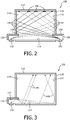
- FIG. 1A is a top view of of a luminaire 100 not according to the invention.
- the luminaire 100 includes a first light mixing chamber 110 and a second light mixing chamber 120 coupled to the first chamber 110.
- the second chamber 120 includes a plurality of light sources 130.
- the light sources 130 can be configured to, in combination, generate several different colors of light, for example, with one or more LEDs 132 arranged in groups of similar or dissimilar colors.
- light emitted by the light sources 130 travels from the second chamber 120 into the first chamber 110, where at least a portion of the light is mixed.
- a light exit surface 112 is coupled to the first chamber 110 and configured to permit at least some of the light within the first chamber 110 to travel through the light exit surface 112 such that the light exiting the surface 112 is directly viewable by an observer.
- the light sources 130 can include non-LED light sources, such as traditional fluorescent, high-intensity discharge (HID), and incandescent lamps. Further, any of the preceding may be employed alone or in combination with one another and/or LEDs in luminaires in accordance with various embodiments of the invention.
- the light sources 130 can be included in a lighting unit or a plurality of lighting units. In further embodiments, the light sources can be included in a multi-channel lighting unit or a plurality of multi-channel lighting units.
- FIG. 1B is a side cross-section view of the luminaire 100 of FIG. 1A along a cut line 1A-1A.
- the first chamber 110 generally has dimensions of D depth and H height.
- the height H is approximately 6 centimeters (cm) or less, allowing the luminaire 100 to have a low profile, although it should be appreciated that heights greater than 6 cm can be used.
- the second chamber 120 includes an opening 134 in communication with the first chamber 110, and at least one wall 136.
- the wall 136 protrudes into the first chamber 110 by a dimension d 1 .
- the wall 136 is configured to prevent light emitted by the light sources 130, a portion of which is shown by dashed line 140, from directly impinging upon the light exit surface 112.
- LED 132 may travel away from the LED in several directions, only light traveling away from the LED within an angular range of ⁇ degrees (as shown in FIG. 1B ) will directly travel through the opening 134 from the second chamber 120 into the first chamber 110, such as the portion of light indicated at 140.
- no light emitted from the LED 132 can directly impinge upon the light exit surface 112 because there is no line-of-sight between the LED 132 and the light exit surface 112. This forces the light to interact with at least the first chamber 110, where it is mixed, before it reaches the light exit surface 112.
- some of the light emitted by the light sources 130 may optionally be mixed in the second chamber 120 before entering the first chamber 110.
- the light exit surface 112 includes a light transmissive diffuser.
- the diffusive property of the light exit surface 112 compensates for the variations in brightness of the light in the first chamber 110 by uniformly mixing the light such that all light exiting the surface 112 (e.g., light directly viewable from the luminaire 100) is substantially uniform in brightness and color. Consequently, individual light sources (e.g., LED 132) and individual colors emitted by the light sources 130 are not discernable by an observer directly viewing the light exit surface 112.
- the geometry of the luminaire 100 provides for light mixing within at least the first chamber 110 and prevents light from the light sources 130 from directly impinging upon the light exit surface 112.
- the first chamber 110 is larger than the second chamber 120.
- the first chamber 110, the second chamber 120, the wall 136 and the light sources 130 in combination enable the luminaire 100 to have a low profile of approximately 6 cm or less at least because the wall 136 prevents light from directly impinging upon the light exit surface 112 regardless of the height H of the first chamber 110.
- the light is forced to mix in the first chamber 110 before traveling through the light exit surface 112, which aids in producing uniformly colored and bright light.
- the depth d 1 at which the wall 136 protrudes into the first chamber 110 can be varied according to the location of the light sources 130 (e.g., LED 132) in the second chamber 120.
- the depth d 1 and/or the location of the light sources 130 may be varied such that the light emitted by the light sources 130 does not directly impinge upon the light exit surface 112.
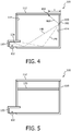
- the luminaire 100 includes a third light mixing chamber 150 coupled to the first chamber 110 in a manner similar to the second chamber 120, but at a different location on the first chamber 110.
- the third chamber 150 includes at least one wall 156, which protrudes into the first chamber 110.
- the second chamber 120 contains a first portion of the light sources 130, for example, LED (or LEDs) 132, and the third chamber 150 contains a second portion of the light sources 130, for example, LED (or LEDs) 152.
- the first portion of the light sources 130 may all be configured to emit a single color of light or several different colors of light.
- the second portion of the light sources 130 may be configured to emit a single color of light, for example, a color the same as or different than the first portion, or several different colors of light.
- any number of light mixing chambers can be coupled to the first chamber 110 in a manner similar to the second chamber 120 and/or the third chamber 150.
- each light mixing chamber can include one or more lighting units and/or multi-channel lighting units.
- one or more of the light sources 130 e.g., individual LEDs
- the first chamber 110 of the luminaire 100 includes at least one light reflecting surface 114.
- the light reflecting surface(s) 114 may, for example, be located on or near the sidewalls or bottom wall of the first chamber 110, and may face generally toward an interior portion of the first chamber 110 such that light within the first chamber 110 reflects off of the surface(s) 114.
- LED 132 emits light indicated by the dashed lines 142 and LED 152 emits light indicated by the solid lines 144.
- the light 142 enters the first chamber 110 from the second chamber 120, and the light 144 enters the first chamber 110 from the third chamber 150.
- the light 142 and the light 152 is mixed in the first chamber 110 at least in part by reflecting off of the light reflecting surface(s) 114 one or more times before reaching the light exit surface 112.
- the light reflecting surface 114 can, in some embodiments, include a light diffusive reflecting surface, which further aids in the mixing of the light by scattering light reflected off of the surface 114 in several different directions.
- the second chamber 120 and/or the third chamber 150 include one or more light reflecting surfaces (not shown). Some of the light 142 is mixed within the second chamber 120 and some of the light 144 is mixed within the third chamber 150 by reflecting off of the light reflecting surfaces therein.
- the light 142 is a first color of light
- the light 144 is a second color of light different from the first color. At least some of the light 142, 144 is reflected by the reflecting surfaces 114 in the first chamber 110 such that the light 142, 144 arrives at common points 146 of the light exit surface 112, causing the light 142, 144, and therefore the different colors, to mix at the common points 146. Other portions (not shown) of the light 142, 144 arrive at different points on the light exit surface 112.
- the luminaire 100 can include any number of light mixing chambers, according to some embodiments.
- the luminaire 100 includes the first chamber 110 and the second chamber 120.
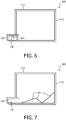
- the first chamber 110 of the luminaire 100 includes at least one light reflecting surface 114.
- the light reflecting surface(s) 114 may, for example, be located on or near the sidewalls or bottom wall of the first chamber 110, and may face generally toward an interior portion of the first chamber 110 such that light within the first chamber 110 reflects off of the surface(s) 114.
- LED 132 emits light indicated by the dashed lines 140.
- the light 140 enters the first chamber 110 from the second chamber 120, and is mixed in the first chamber 110 by reflecting off of the light reflecting surface(s) 114 one or more times before impinging upon the light exit surface 112.
- the light reflecting surface 114 can, in some embodiments, include a light diffusive reflecting surface, which further aids in the mixing of the light by scattering light reflected off of the surface 114 in several different directions.
- the second chamber 120 includes at least one light reflecting surface 124. Some of the light 140 emitted by the LED 132 can be mixed in the second chamber 120 by reflecting off of the light reflecting surface(s) 124 of the second chamber before entering the first chamber 110.
- the second chamber 120 may include at least one light reflecting surface therein.
- light from LED 132 shown by dashed lines 146 and 148, travels away from the LED 132 in different directions and reflects off of the light reflecting surfaces 114 and 124, mixing within the first chamber 110 and/or second chamber 120.
- Some of the light 146, 148 reflects off of the light reflecting surface 114 at a common point of incidence 160 in the same direction (i.e., the light 146 and 148 overlaps after reflecting off of the point 160), shown by line 162, and arrives at a point 164 on the light exit surface 112.
- the light 162 therefore includes a combination of the light 146 and 148.
- the light 162 includes a mixture of the different colors. This is possible because the reflections off of the light reflecting surfaces 114 (and, optionally, light reflecting surfaces 124) are diffuse. When other light (not shown) arrives at other points of the light exit surface 112 in a similar manner to the light 162, the result is that all or nearly all light reaching the light exit surface 112 is substantially uniform in color.
- the light exit surface 112 in some embodiments, may be configured to further mix the light to provide additional improvements in uniformity of color and brightness.
- the light mixing chambers may be used to mix light, in particular, different colors of light.
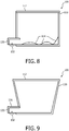
- a transmissive diffuser 170 is disposed within the first chamber 110 between the light exit surface 112 and the second chamber 120.
- the transmissive diffuser 170 is configured to further mix the light within the first chamber 110 by diffusing light traveling within the first chamber 110 before the light reaches the light exit surface 112.
- the luminaire 100 may optionally include multiple transmissive diffusers disposed within the first chamber 110 between the light exit surface 112 and the second chamber 120.
- the transmissive diffuser 170 may be oriented horizontally across the interior of the first chamber 110 or at another angle to mix light in one of a number of different ways. In another embodiment, the transmissive diffuser 170 may extend across a portion of the interior of the first chamber 110. In various embodiments, the use of multiple transmissive diffusers can act to more completely mix the light observed at the light exit surface 112.
- a lens, prism, specular reflector, or diffuser 172 is disposed within the opening 134 of the second chamber 120.
- the lens, prism, specular reflector, or diffuser 172 is configured to mix the light traveling from the second chamber 120 to the first chamber 110 before it reaches the first chamber 110.
- the lens, prism, or specular reflector 172 may be disposed upon one or more of the LEDs 132 to mix or redirect the light as it is emitted, for example to direct the light toward a particular location or locations in the first mixing chamber in order to improve color mixing or uniformity.
- the transmissive diffuser 170 (or multiple transmissive diffusers) in the first chamber 110 can be employed in combination with the element 172 included in the opening 134.
- the luminaire 100 may include one or more light reflecting surfaces 114.
- the light reflecting surface(s) 114 are substantially parallel to the interior side, top or bottom walls of the first chamber 110 and/or other chambers (e.g., the second chamber 120 and the third chamber 150), such as shown in FIG. 2 .
- the first chamber 110 are tilted.
- at least some of the light reflecting surfaces of the second chamber 120 are tilted.
- the light reflecting surfaces 114 of the first chamber 110 are curved in one or more dimensions. As with the titled reflecting surfaces described above, adjusting the curves of the reflecting surface(s) 114 aids in mixing by varying the number of reflections and/or directions of light reflected therefrom.
- the light reflecting surface(s) 114 may include bumps and/or other textures (not shown), which may be distributed evenly or unevenly within the first chamber 110 and/or second chamber 120. Such bumps or textures can be used to further improve the mixing of light using the diverse reflective characteristics of the surface(s) 114.
- one or more sidewalls of the first chamber 110 of the luminaire 100 are flared inward or outward.
- the sidewalls may be straight or curved.
- flared sidewalls provide similar light mixing benefits to those described above with reference to the tilted or curved light reflecting surfaces in FIGS. 7 and 8 , as will be appreciated by one of skill in the art.
- the second chamber 120 (and other chambers, such as the third chamber 150 shown in FIG. 2 ) may protrude into the first chamber 110 by some distance d 1 , for example, as shown in FIG. 1B .
- Other geometric configurations of the various light mixing chambers are possible.
- the second chamber 120 is contained entirely within the first chamber 110 of the luminaire 100.
- one end of the second chamber 120 is flush with a sidewall of the first chamber 110, allowing the luminaire 100 to be relatively compact in size.
- the wall 136 is configured to prevent light emitted from the light sources (e.g., LED 132) from directly impinging upon the light exit surface 112.
- FIG. 11 Another geometric configuration is shown in FIG. 11 where the second chamber 120 is external to the first chamber 110 of the luminaire 100, according to one embodiment.
- the wall 136 does not protrude into the first chamber 110.
- the LEDs 132 are oriented to face toward the center of the first chamber 110 instead of upward (such as shown in the luminaire 100 of FIG. 1B ).
- the location and/or orientation of the second chamber 120 and/or the light sources may vary, providing flexibility in the design, construction and performance of the luminaire 100. For example, by orienting the LED 132 towards the first chamber 110, more light can directly enter the first chamber 110 (depending on the emission characteristics of the LED 132), which can provide a more efficient use of the light.
- FIGS. 13, 14 and 15 show several embodiments of the luminaire 100 having multiple second, small chambers 120.
- the second chambers 120 may be placed on alternating sides of the first chamber 110 (as in FIG. 13 ), all on the same side of the first chamber 110 (as in FIG. 14 ), or on opposite ends of the first chamber 110 (as in FIG. 15 ).
- other arrangements of the second chamber 120 are possible for adapting the size and shape of the luminaire 100 for different applications (e.g., mounting the luminaire 100 in very small or non-uniformly shaped spaces), for adapting the luminaire 100 to provide illumination in various directions, or to provide other aesthetic characteristics).
- the luminaire 100 is configured to be modular, in that any number of second chambers 120 can be coupled to the first chamber 110 to build, for example, a fixture as small as a few centimeters in any dimension, or as large as a ceiling of a room.
- the light sources 130 include tunable white, RGB, and/or RGBWA lights.
- the light sources 130 may include 15 LEDs in three groups of five (each group contained within a different second chamber 120). Each group of LEDs may include an amber, green, blue, red and white LED, or other types, colors or numbers of LEDs. Other combinations of LEDs are possible to provide various colors and amounts of light output.
- the sizes of the first chamber 110 and the second chamber 120 can be varied relative to one another.
- the first chamber 110 is a large chamber relative to the size of one or more second chambers 120 that are coupled to it.
- the dimensions of the second chamber may vary from the dimensions of the third chamber.
- one or more LED-based direct view luminaires 100 may be coupled to a controller over a network.
- the network provides a communication path between the controller and each luminaire.
- several luminaires may be arranged to provide light across a large space.
- the luminaires may be controlled individually, in groups or all together by the controller, for example, to control the brightness and/or color of any one or more of the luminaires.
- the phrase "at least one,” in reference to a list of one or more elements, should be understood to mean at least one element selected from any one or more of the elements in the list of elements, but not necessarily including at least one of each and every element specifically listed within the list of elements and not excluding any combinations of elements in the list of elements.
- This definition also allows that elements may optionally be present other than the elements specifically identified within the list of elements to which the phrase "at least one" refers, whether related or unrelated to those elements specifically identified.
Landscapes
- Engineering & Computer Science (AREA)
- General Engineering & Computer Science (AREA)
- Physics & Mathematics (AREA)
- Microelectronics & Electronic Packaging (AREA)
- Optics & Photonics (AREA)
- Non-Portable Lighting Devices Or Systems Thereof (AREA)
- Led Device Packages (AREA)
Claims (12)
- Luminaire (100), comprenant:une pluralité de sources de lumière (130, 132) configurées, en combinaison, pour générer une pluralité de couleurs de lumière différentes ;une première chambre (110) configurée pour mélanger la pluralité de couleurs de lumière différentes ;au moins une surface de sortie de lumière (112) couplée à la première chambre et configurée pour mélanger davantage la lumière émise par la pluralité de sources de lumière ; etune deuxième chambre (120) contenant la pluralité de sources de lumière et ayant au moins une paroi (136) et une ouverture (134) en communication avec la première chambre, l'au moins une paroi étant configurée pour empêcher la lumière émise par la pluralité de sources de lumière d'arriver directement sur l'au moins une surface de sortie de lumière, et l'ouverture étant configurée pour permettre à la lumière émise par la pluralité de sources de lumière de circuler à travers l'ouverture de la deuxième chambre à la première chambre,dans lequel la première chambre et l'au moins une surface de sortie de lumière sont configurées conjointement pour mélanger la lumière émise par la pluralité de sources de lumière de sorte que toute la lumière sortant de l'au moins une surface de sortie de lumière soit sensiblement uniforme en termes de luminosité et/ou de couleur,
et dans lequel le luminaire comprend en outre au moins l'un parmi une lentille, un prisme, un réflecteur spéculaire, et un diffuseur de lumière (172) disposé dans l'ouverture,
caractérisé en ce que la pluralité de sources de lumière est une première pluralité de sources de lumière, et le luminaire comprend en outre une troisième chambre (150) en communication de lumière avec la première chambre et contenant une seconde pluralité de sources de lumière (130, 152),
dans lequel la première pluralité de sources de lumière est configurée pour générer un premier jeu de couleurs de lumière et la seconde pluralité de sources de lumière est configurée pour générer un second jeu de couleurs de lumière qui est différent du premier jeu de couleurs de sorte qu'une combinaison du premier jeu de couleurs et du second jeu de couleurs fournisse la pluralité de couleurs de lumière différentes. - Luminaire (100) selon la revendication 1, dans lequel l'au moins une surface de sortie de lumière (112) comporte au moins une surface diffusive transmissive.
- Luminaire (100) selon la revendication 1, dans lequel la deuxième chambre (120) est configurée pour mélanger la lumière émise par la pluralité de sources de lumière.
- Luminaire (100) selon la revendication 1, dans lequel la première chambre (110) comporte au moins une surface réfléchissant la lumière (114).
- Luminaire (100) selon la revendication 4, dans lequel l'au moins une surface réfléchissant la lumière (114) comporte au moins une surface diffusive réfléchissante.
- Luminaire (100) selon la revendication 4, dans lequel l'au moins une surface réfléchissant la lumière (114) est configurée pour réfléchir au moins une portion de la lumière émise par la pluralité de sources de lumière (130, 132) vers l'au moins une surface de sortie de lumière (112).
- Luminaire (100) selon la revendication 6, dans lequel l'au moins une surface réfléchissant la lumière (114) est au moins une première surface réfléchissant la lumière, et
dans lequel la deuxième chambre (120) comporte au moins une seconde surface réfléchissant la lumière (124). - Luminaire (100) selon la revendication 7, dans lequel la portion de la lumière émise par la pluralité de sources de lumière (130, 132) est une première portion de la lumière émise par la pluralité de sources de lumière, et
dans lequel l'au moins une seconde surface réfléchissant la lumière (124) est configurée pour réfléchir au moins une seconde portion de la lumière émise par la pluralité de sources de lumière qui est différente de la première portion, vers l'au moins une première surface réfléchissant la lumière (114). - Luminaire (100) selon la revendication 8, dans lequel l'au moins une première surface réfléchissant la lumière (114) comporte un point de réflexion de lumière incidente sur celle-ci, et
dans lequel l'au moins une seconde surface réfléchissant la lumière (124) est en outre configurée pour réfléchir la seconde portion de la lumière vers le point de réflexion de lumière incidente de sorte que les première et seconde portions de la lumière soient toutes deux réfléchies par la première surface réfléchissant la lumière vers l'au moins une surface de sortie de lumière dans une même direction depuis le point de réflexion de lumière incidente. - Luminaire (100) selon la revendication 1, comprenant en outre un diffuseur de lumière transmissive (170) disposé dans la première chambre (110) entre l'ouverture (134) et l'au moins une surface de sortie de lumière (112).
- Luminaire (100) selon la revendication 1, dans lequel le premier jeu de couleurs de lumière est une première couleur de lumière unique (142), et
dans lequel le second jeu de couleurs de lumière est une seconde couleur de lumière unique (144). - Luminaire (100) selon la revendication 1, dans lequel la pluralité de sources de lumière (130, 132) est la première pluralité de sources de lumière, et
dans lequel le luminaire comprend en outre une première unité d'éclairage multicanal comportant la première pluralité de sources de lumière, une seconde unité d'éclairage multicanal comportant la seconde pluralité de sources de lumière, et une troisième chambre en communication de lumière avec la première chambre et contenant la seconde unité d'éclairage multicanal.
Applications Claiming Priority (2)
| Application Number | Priority Date | Filing Date | Title |
|---|---|---|---|
| US201161560970P | 2011-11-17 | 2011-11-17 | |
| PCT/IB2012/056494 WO2013072885A1 (fr) | 2011-11-17 | 2012-11-16 | Luminaire à vision directe à diodes électroluminescentes présentant un mélange uniforme du flux lumineux |
Publications (2)
| Publication Number | Publication Date |
|---|---|
| EP2748520A1 EP2748520A1 (fr) | 2014-07-02 |
| EP2748520B1 true EP2748520B1 (fr) | 2017-03-01 |
Family
ID=47628401
Family Applications (1)
| Application Number | Title | Priority Date | Filing Date |
|---|---|---|---|
| EP12819135.0A Active EP2748520B1 (fr) | 2011-11-17 | 2012-11-16 | Luminaire à vision directe à diodes électroluminescentes présentant un mélange uniforme du flux lumineux |
Country Status (7)
| Country | Link |
|---|---|
| US (1) | US9551466B2 (fr) |
| EP (1) | EP2748520B1 (fr) |
| JP (1) | JP6588701B2 (fr) |
| CN (1) | CN103930714B (fr) |
| IN (1) | IN2014CN03658A (fr) |
| RU (1) | RU2633391C2 (fr) |
| WO (1) | WO2013072885A1 (fr) |
Families Citing this family (10)
| Publication number | Priority date | Publication date | Assignee | Title |
|---|---|---|---|---|
| US9425896B2 (en) * | 2013-12-31 | 2016-08-23 | Xicato, Inc. | Color modulated LED-based illumination |
| EP2942617A1 (fr) * | 2014-05-08 | 2015-11-11 | Image Engineering GmbH & Co. KG | Dispositif d'éclairage |
| CN115539867A (zh) | 2015-09-24 | 2022-12-30 | 卡任特照明解决方案有限公司 | 照明装置 |
| US10100984B2 (en) | 2015-10-15 | 2018-10-16 | GE Lighting Solutions, LLC | Indirect light mixing LED module for point-source applications |
| ITUA20161504A1 (it) * | 2016-03-09 | 2017-09-09 | Neri S P A | Ottica e corpo illuminante |
| KR102565959B1 (ko) * | 2016-04-29 | 2023-08-14 | 엘지이노텍 주식회사 | 조명 모듈 및 이를 구비한 조명 장치 |
| DE102017208999A1 (de) * | 2017-05-29 | 2018-11-29 | Volkswagen Aktiengesellschaft | Beleuchtungsvorrichtung zur Beleuchtung des Innenraums eines Kraftfahrzeugs |
| DE102017006756B4 (de) | 2017-07-17 | 2019-11-07 | Emz-Hanauer Gmbh & Co. Kgaa | Farbtemperaturvariable Leuchtvorrichtung sowie elektrisches Haushaltsgerät mit einer solchen Leuchtvorrichtung |
| EP3655696B1 (fr) | 2017-07-21 | 2020-12-23 | Signify Holding B.V. | Module électroluminescent |
| CN115135924A (zh) | 2020-02-18 | 2022-09-30 | 昕诺飞控股有限公司 | 光混合室和照明器 |
Citations (1)
| Publication number | Priority date | Publication date | Assignee | Title |
|---|---|---|---|---|
| WO2008011723A2 (fr) * | 2006-07-28 | 2008-01-31 | Tir Technology Lp | Module d'éclairage ayant des directions de propagation de chaleur et de lumière similaires |
Family Cites Families (28)
| Publication number | Priority date | Publication date | Assignee | Title |
|---|---|---|---|---|
| US6211626B1 (en) | 1997-08-26 | 2001-04-03 | Color Kinetics, Incorporated | Illumination components |
| US6016038A (en) | 1997-08-26 | 2000-01-18 | Color Kinetics, Inc. | Multicolored LED lighting method and apparatus |
| US7040774B2 (en) | 2003-05-23 | 2006-05-09 | Goldeneye, Inc. | Illumination systems utilizing multiple wavelength light recycling |
| US6995355B2 (en) * | 2003-06-23 | 2006-02-07 | Advanced Optical Technologies, Llc | Optical integrating chamber lighting using multiple color sources |
| DE10349788A1 (de) * | 2003-10-24 | 2005-05-25 | LiSol Gesellschaft für Licht- und Solartechnik mbH | Leuchte mit einem Grundkörper aus lichtdurchlässigem Kunststoffmaterial |
| US7506996B2 (en) * | 2004-01-22 | 2009-03-24 | Continental Automotive Systems Us, Inc. | Illuminated display having two single-colored light sources |
| JP4694567B2 (ja) | 2004-06-29 | 2011-06-08 | コーニンクレッカ フィリップス エレクトロニクス エヌ ヴィ | Led照明 |
| JP4560650B2 (ja) * | 2004-11-22 | 2010-10-13 | ライツ・アドバンスト・テクノロジー株式会社 | バックライトユニット |
| DE102005035007B4 (de) * | 2005-07-22 | 2008-03-20 | Erco Leuchten Gmbh | Leuchte |
| JP4729720B2 (ja) | 2005-12-21 | 2011-07-20 | 株式会社 日立ディスプレイズ | 面状照明装置及びこの面状照明装置をバックライトとした液晶表示装置 |
| RU2309441C1 (ru) * | 2006-03-10 | 2007-10-27 | Закрытое акционерное общество "Конструкторское бюро Технотроник" | Жидкокристаллический экран |
| TW200827872A (en) | 2006-10-26 | 2008-07-01 | Koninkl Philips Electronics Nv | Illumination system and display device |
| CN101611262B (zh) * | 2007-02-16 | 2011-01-26 | 夏普株式会社 | 背光装置和使用该背光装置的平面显示装置 |
| TW200907502A (en) | 2007-05-21 | 2009-02-16 | Rohm & Haas Denmark Finance As | Mini lightbar illuminators for LCD displays |
| CN101680606B (zh) | 2007-05-24 | 2013-01-02 | 皇家飞利浦电子股份有限公司 | 颜色可调照明系统 |
| EP2843464A1 (fr) * | 2007-05-29 | 2015-03-04 | Koninklijke Philips N.V. | Dispositif d'éclairage ayant une fenêtre de sortie de lumière |
| US7942556B2 (en) * | 2007-06-18 | 2011-05-17 | Xicato, Inc. | Solid state illumination device |
| JP2009043636A (ja) | 2007-08-10 | 2009-02-26 | Mitsubishi Electric Corp | 面状光源装置および表示装置 |
| CN101430066A (zh) | 2007-11-06 | 2009-05-13 | 富士迈半导体精密工业(上海)有限公司 | 半导体固态光源模块及半导体固态光源模组 |
| US20090122227A1 (en) | 2007-11-08 | 2009-05-14 | Rohm And Haas Denmark Finance A/S | Integrated backlight illumination assembly |
| TW200933075A (en) * | 2008-01-21 | 2009-08-01 | Jiahn-Chang Wu | Reflection type lamp |
| JP2011034674A (ja) * | 2008-02-05 | 2011-02-17 | Asagi Create:Kk | 面状光源および電飾看板 |
| EP2263039A1 (fr) * | 2008-04-03 | 2010-12-22 | Koninklijke Philips Electronics N.V. | Dispositif emetteur de lumiere blanche ameliore |
| US7980728B2 (en) * | 2008-05-27 | 2011-07-19 | Abl Ip Holding Llc | Solid state lighting using light transmissive solid in or forming optical integrating volume |
| JP2010040296A (ja) | 2008-08-04 | 2010-02-18 | Harison Toshiba Lighting Corp | アレイ光源用光学素子及びそれを用いた発光装置 |
| US8434887B2 (en) | 2009-08-27 | 2013-05-07 | Dolby Laboratories Licensing Corporation | Optical mixing and shaping system for display backlights and displays incorporating the same |
| US9163802B2 (en) * | 2009-12-02 | 2015-10-20 | Abl Ip Holding Llc | Lighting fixtures using solid state device and remote phosphors to produce white light |
| ITPR20100021A1 (it) | 2010-03-23 | 2011-09-24 | Coemar Spa | Proiettore luminoso a led con unico fascio riflesso |
-
2012
- 2012-11-16 CN CN201280056423.4A patent/CN103930714B/zh active Active
- 2012-11-16 US US14/359,249 patent/US9551466B2/en active Active
- 2012-11-16 EP EP12819135.0A patent/EP2748520B1/fr active Active
- 2012-11-16 RU RU2014124351A patent/RU2633391C2/ru active
- 2012-11-16 JP JP2014541805A patent/JP6588701B2/ja active Active
- 2012-11-16 WO PCT/IB2012/056494 patent/WO2013072885A1/fr active Application Filing
- 2012-11-16 IN IN3658CHN2014 patent/IN2014CN03658A/en unknown
Patent Citations (1)
| Publication number | Priority date | Publication date | Assignee | Title |
|---|---|---|---|---|
| WO2008011723A2 (fr) * | 2006-07-28 | 2008-01-31 | Tir Technology Lp | Module d'éclairage ayant des directions de propagation de chaleur et de lumière similaires |
Also Published As
| Publication number | Publication date |
|---|---|
| RU2014124351A (ru) | 2015-12-27 |
| RU2633391C2 (ru) | 2017-10-12 |
| CN103930714A (zh) | 2014-07-16 |
| CN103930714B (zh) | 2016-08-24 |
| EP2748520A1 (fr) | 2014-07-02 |
| JP6588701B2 (ja) | 2019-10-09 |
| US9551466B2 (en) | 2017-01-24 |
| IN2014CN03658A (fr) | 2015-10-16 |
| JP2014533876A (ja) | 2014-12-15 |
| US20140321115A1 (en) | 2014-10-30 |
| WO2013072885A1 (fr) | 2013-05-23 |
Similar Documents
| Publication | Publication Date | Title |
|---|---|---|
| EP2748520B1 (fr) | Luminaire à vision directe à diodes électroluminescentes présentant un mélange uniforme du flux lumineux | |
| US10292225B2 (en) | Methods and apparatus for adaptable lighting unit | |
| EP2802805B1 (fr) | Appareil d'éclairage en vue directe à base de del avec apparence d'éclairage uniforme | |
| EP2745041B1 (fr) | Luminaire à base de diodes électroluminescentes ayant une optique de mélange | |
| US20150173151A1 (en) | Tunable correlated color temperature led-based white light source with mixing chamber and remote phosphor exit window | |
| US20140204586A1 (en) | LED-based Lighting Unit With Optical Component for Mixing Light Output from a Plurality of LEDs | |
| CA2837519A1 (fr) | Luminaire a base de del a lentille texturee | |
| US10061071B2 (en) | Panel luminaire | |
| WO2016071845A1 (fr) | Lentille asymétrique et appareil d'éclairage linéaire | |
| US20170175975A1 (en) | Method and apparatus for an asymmetric optical lens | |
| US10746362B1 (en) | Wall wash luminaire | |
| US10241309B2 (en) | Forward throw asymmetric optic design | |
| US10036538B2 (en) | Method and apparatus for uniform illumination of a surface |
Legal Events
| Date | Code | Title | Description |
|---|---|---|---|
| PUAI | Public reference made under article 153(3) epc to a published international application that has entered the european phase |
Free format text: ORIGINAL CODE: 0009012 |
|
| 17P | Request for examination filed |
Effective date: 20140325 |
|
| AK | Designated contracting states |
Kind code of ref document: A1 Designated state(s): AL AT BE BG CH CY CZ DE DK EE ES FI FR GB GR HR HU IE IS IT LI LT LU LV MC MK MT NL NO PL PT RO RS SE SI SK SM TR |
|
| DAX | Request for extension of the european patent (deleted) | ||
| 17Q | First examination report despatched |
Effective date: 20150701 |
|
| RAP1 | Party data changed (applicant data changed or rights of an application transferred) |
Owner name: PHILIPS LIGHTING HOLDING B.V. |
|
| GRAJ | Information related to disapproval of communication of intention to grant by the applicant or resumption of examination proceedings by the epo deleted |
Free format text: ORIGINAL CODE: EPIDOSDIGR1 |
|
| GRAP | Despatch of communication of intention to grant a patent |
Free format text: ORIGINAL CODE: EPIDOSNIGR1 |
|
| RIC1 | Information provided on ipc code assigned before grant |
Ipc: F21Y 113/10 20160101ALI20160823BHEP Ipc: F21Y 115/10 20160101ALN20160823BHEP Ipc: F21V 7/00 20060101ALI20160823BHEP Ipc: F21S 10/02 20060101AFI20160823BHEP |
|
| INTG | Intention to grant announced |
Effective date: 20160922 |
|
| GRAS | Grant fee paid |
Free format text: ORIGINAL CODE: EPIDOSNIGR3 |
|
| GRAA | (expected) grant |
Free format text: ORIGINAL CODE: 0009210 |
|
| AK | Designated contracting states |
Kind code of ref document: B1 Designated state(s): AL AT BE BG CH CY CZ DE DK EE ES FI FR GB GR HR HU IE IS IT LI LT LU LV MC MK MT NL NO PL PT RO RS SE SI SK SM TR |
|
| REG | Reference to a national code |
Ref country code: GB Ref legal event code: FG4D |
|
| REG | Reference to a national code |
Ref country code: CH Ref legal event code: EP Ref country code: AT Ref legal event code: REF Ref document number: 871813 Country of ref document: AT Kind code of ref document: T Effective date: 20170315 |
|
| REG | Reference to a national code |
Ref country code: IE Ref legal event code: FG4D |
|
| REG | Reference to a national code |
Ref country code: DE Ref legal event code: R096 Ref document number: 602012029358 Country of ref document: DE |
|
| REG | Reference to a national code |
Ref country code: NL Ref legal event code: MP Effective date: 20170301 |
|
| REG | Reference to a national code |
Ref country code: LT Ref legal event code: MG4D |
|
| REG | Reference to a national code |
Ref country code: AT Ref legal event code: MK05 Ref document number: 871813 Country of ref document: AT Kind code of ref document: T Effective date: 20170301 |
|
| PG25 | Lapsed in a contracting state [announced via postgrant information from national office to epo] |
Ref country code: FI Free format text: LAPSE BECAUSE OF FAILURE TO SUBMIT A TRANSLATION OF THE DESCRIPTION OR TO PAY THE FEE WITHIN THE PRESCRIBED TIME-LIMIT Effective date: 20170301 Ref country code: NO Free format text: LAPSE BECAUSE OF FAILURE TO SUBMIT A TRANSLATION OF THE DESCRIPTION OR TO PAY THE FEE WITHIN THE PRESCRIBED TIME-LIMIT Effective date: 20170601 Ref country code: LT Free format text: LAPSE BECAUSE OF FAILURE TO SUBMIT A TRANSLATION OF THE DESCRIPTION OR TO PAY THE FEE WITHIN THE PRESCRIBED TIME-LIMIT Effective date: 20170301 Ref country code: HR Free format text: LAPSE BECAUSE OF FAILURE TO SUBMIT A TRANSLATION OF THE DESCRIPTION OR TO PAY THE FEE WITHIN THE PRESCRIBED TIME-LIMIT Effective date: 20170301 Ref country code: GR Free format text: LAPSE BECAUSE OF FAILURE TO SUBMIT A TRANSLATION OF THE DESCRIPTION OR TO PAY THE FEE WITHIN THE PRESCRIBED TIME-LIMIT Effective date: 20170602 |
|
| RIN2 | Information on inventor provided after grant (corrected) |
Inventor name: ROBERGE, BRAIN Inventor name: GOLDSTEIN, PETER ISAAC Inventor name: ROTH, ERIC ANTHONY |
|
| PG25 | Lapsed in a contracting state [announced via postgrant information from national office to epo] |
Ref country code: ES Free format text: LAPSE BECAUSE OF FAILURE TO SUBMIT A TRANSLATION OF THE DESCRIPTION OR TO PAY THE FEE WITHIN THE PRESCRIBED TIME-LIMIT Effective date: 20170301 Ref country code: AT Free format text: LAPSE BECAUSE OF FAILURE TO SUBMIT A TRANSLATION OF THE DESCRIPTION OR TO PAY THE FEE WITHIN THE PRESCRIBED TIME-LIMIT Effective date: 20170301 Ref country code: LV Free format text: LAPSE BECAUSE OF FAILURE TO SUBMIT A TRANSLATION OF THE DESCRIPTION OR TO PAY THE FEE WITHIN THE PRESCRIBED TIME-LIMIT Effective date: 20170301 Ref country code: SE Free format text: LAPSE BECAUSE OF FAILURE TO SUBMIT A TRANSLATION OF THE DESCRIPTION OR TO PAY THE FEE WITHIN THE PRESCRIBED TIME-LIMIT Effective date: 20170301 Ref country code: RS Free format text: LAPSE BECAUSE OF FAILURE TO SUBMIT A TRANSLATION OF THE DESCRIPTION OR TO PAY THE FEE WITHIN THE PRESCRIBED TIME-LIMIT Effective date: 20170301 Ref country code: BG Free format text: LAPSE BECAUSE OF FAILURE TO SUBMIT A TRANSLATION OF THE DESCRIPTION OR TO PAY THE FEE WITHIN THE PRESCRIBED TIME-LIMIT Effective date: 20170601 |
|
| PG25 | Lapsed in a contracting state [announced via postgrant information from national office to epo] |
Ref country code: NL Free format text: LAPSE BECAUSE OF FAILURE TO SUBMIT A TRANSLATION OF THE DESCRIPTION OR TO PAY THE FEE WITHIN THE PRESCRIBED TIME-LIMIT Effective date: 20170301 |
|
| PG25 | Lapsed in a contracting state [announced via postgrant information from national office to epo] |
Ref country code: IT Free format text: LAPSE BECAUSE OF FAILURE TO SUBMIT A TRANSLATION OF THE DESCRIPTION OR TO PAY THE FEE WITHIN THE PRESCRIBED TIME-LIMIT Effective date: 20170301 Ref country code: SK Free format text: LAPSE BECAUSE OF FAILURE TO SUBMIT A TRANSLATION OF THE DESCRIPTION OR TO PAY THE FEE WITHIN THE PRESCRIBED TIME-LIMIT Effective date: 20170301 Ref country code: RO Free format text: LAPSE BECAUSE OF FAILURE TO SUBMIT A TRANSLATION OF THE DESCRIPTION OR TO PAY THE FEE WITHIN THE PRESCRIBED TIME-LIMIT Effective date: 20170301 Ref country code: CZ Free format text: LAPSE BECAUSE OF FAILURE TO SUBMIT A TRANSLATION OF THE DESCRIPTION OR TO PAY THE FEE WITHIN THE PRESCRIBED TIME-LIMIT Effective date: 20170301 Ref country code: EE Free format text: LAPSE BECAUSE OF FAILURE TO SUBMIT A TRANSLATION OF THE DESCRIPTION OR TO PAY THE FEE WITHIN THE PRESCRIBED TIME-LIMIT Effective date: 20170301 |
|
| REG | Reference to a national code |
Ref country code: FR Ref legal event code: PLFP Year of fee payment: 6 |
|
| PG25 | Lapsed in a contracting state [announced via postgrant information from national office to epo] |
Ref country code: PT Free format text: LAPSE BECAUSE OF FAILURE TO SUBMIT A TRANSLATION OF THE DESCRIPTION OR TO PAY THE FEE WITHIN THE PRESCRIBED TIME-LIMIT Effective date: 20170703 Ref country code: IS Free format text: LAPSE BECAUSE OF FAILURE TO SUBMIT A TRANSLATION OF THE DESCRIPTION OR TO PAY THE FEE WITHIN THE PRESCRIBED TIME-LIMIT Effective date: 20170701 Ref country code: SM Free format text: LAPSE BECAUSE OF FAILURE TO SUBMIT A TRANSLATION OF THE DESCRIPTION OR TO PAY THE FEE WITHIN THE PRESCRIBED TIME-LIMIT Effective date: 20170301 Ref country code: PL Free format text: LAPSE BECAUSE OF FAILURE TO SUBMIT A TRANSLATION OF THE DESCRIPTION OR TO PAY THE FEE WITHIN THE PRESCRIBED TIME-LIMIT Effective date: 20170301 |
|
| REG | Reference to a national code |
Ref country code: DE Ref legal event code: R097 Ref document number: 602012029358 Country of ref document: DE |
|
| PLBE | No opposition filed within time limit |
Free format text: ORIGINAL CODE: 0009261 |
|
| STAA | Information on the status of an ep patent application or granted ep patent |
Free format text: STATUS: NO OPPOSITION FILED WITHIN TIME LIMIT |
|
| PG25 | Lapsed in a contracting state [announced via postgrant information from national office to epo] |
Ref country code: DK Free format text: LAPSE BECAUSE OF FAILURE TO SUBMIT A TRANSLATION OF THE DESCRIPTION OR TO PAY THE FEE WITHIN THE PRESCRIBED TIME-LIMIT Effective date: 20170301 |
|
| 26N | No opposition filed |
Effective date: 20171204 |
|
| PG25 | Lapsed in a contracting state [announced via postgrant information from national office to epo] |
Ref country code: SI Free format text: LAPSE BECAUSE OF FAILURE TO SUBMIT A TRANSLATION OF THE DESCRIPTION OR TO PAY THE FEE WITHIN THE PRESCRIBED TIME-LIMIT Effective date: 20170301 |
|
| PG25 | Lapsed in a contracting state [announced via postgrant information from national office to epo] |
Ref country code: MC Free format text: LAPSE BECAUSE OF FAILURE TO SUBMIT A TRANSLATION OF THE DESCRIPTION OR TO PAY THE FEE WITHIN THE PRESCRIBED TIME-LIMIT Effective date: 20170301 |
|
| PG25 | Lapsed in a contracting state [announced via postgrant information from national office to epo] |
Ref country code: CH Free format text: LAPSE BECAUSE OF NON-PAYMENT OF DUE FEES Effective date: 20171130 Ref country code: LI Free format text: LAPSE BECAUSE OF NON-PAYMENT OF DUE FEES Effective date: 20171130 |
|
| PG25 | Lapsed in a contracting state [announced via postgrant information from national office to epo] |
Ref country code: LU Free format text: LAPSE BECAUSE OF NON-PAYMENT OF DUE FEES Effective date: 20171116 |
|
| REG | Reference to a national code |
Ref country code: BE Ref legal event code: MM Effective date: 20171130 |
|
| REG | Reference to a national code |
Ref country code: IE Ref legal event code: MM4A |
|
| PG25 | Lapsed in a contracting state [announced via postgrant information from national office to epo] |
Ref country code: MT Free format text: LAPSE BECAUSE OF NON-PAYMENT OF DUE FEES Effective date: 20171116 |
|
| PG25 | Lapsed in a contracting state [announced via postgrant information from national office to epo] |
Ref country code: IE Free format text: LAPSE BECAUSE OF NON-PAYMENT OF DUE FEES Effective date: 20171116 |
|
| PG25 | Lapsed in a contracting state [announced via postgrant information from national office to epo] |
Ref country code: BE Free format text: LAPSE BECAUSE OF NON-PAYMENT OF DUE FEES Effective date: 20171130 |
|
| PG25 | Lapsed in a contracting state [announced via postgrant information from national office to epo] |
Ref country code: HU Free format text: LAPSE BECAUSE OF FAILURE TO SUBMIT A TRANSLATION OF THE DESCRIPTION OR TO PAY THE FEE WITHIN THE PRESCRIBED TIME-LIMIT; INVALID AB INITIO Effective date: 20121116 |
|
| PG25 | Lapsed in a contracting state [announced via postgrant information from national office to epo] |
Ref country code: CY Free format text: LAPSE BECAUSE OF NON-PAYMENT OF DUE FEES Effective date: 20170301 |
|
| PG25 | Lapsed in a contracting state [announced via postgrant information from national office to epo] |
Ref country code: MK Free format text: LAPSE BECAUSE OF FAILURE TO SUBMIT A TRANSLATION OF THE DESCRIPTION OR TO PAY THE FEE WITHIN THE PRESCRIBED TIME-LIMIT Effective date: 20170301 |
|
| PG25 | Lapsed in a contracting state [announced via postgrant information from national office to epo] |
Ref country code: TR Free format text: LAPSE BECAUSE OF FAILURE TO SUBMIT A TRANSLATION OF THE DESCRIPTION OR TO PAY THE FEE WITHIN THE PRESCRIBED TIME-LIMIT Effective date: 20170301 |
|
| PG25 | Lapsed in a contracting state [announced via postgrant information from national office to epo] |
Ref country code: AL Free format text: LAPSE BECAUSE OF FAILURE TO SUBMIT A TRANSLATION OF THE DESCRIPTION OR TO PAY THE FEE WITHIN THE PRESCRIBED TIME-LIMIT Effective date: 20170301 |
|
| REG | Reference to a national code |
Ref country code: DE Ref legal event code: R082 Ref document number: 602012029358 Country of ref document: DE Representative=s name: MEISSNER BOLTE PATENTANWAELTE RECHTSANWAELTE P, DE Ref country code: DE Ref legal event code: R081 Ref document number: 602012029358 Country of ref document: DE Owner name: SIGNIFY HOLDING B.V., NL Free format text: FORMER OWNER: PHILIPS LIGHTING HOLDING B.V., EINDHOVEN, NL |
|
| P01 | Opt-out of the competence of the unified patent court (upc) registered |
Effective date: 20230421 |
|
| PGFP | Annual fee paid to national office [announced via postgrant information from national office to epo] |
Ref country code: GB Payment date: 20231121 Year of fee payment: 12 |
|
| PGFP | Annual fee paid to national office [announced via postgrant information from national office to epo] |
Ref country code: FR Payment date: 20231123 Year of fee payment: 12 |
|
| PGFP | Annual fee paid to national office [announced via postgrant information from national office to epo] |
Ref country code: DE Payment date: 20240129 Year of fee payment: 12 |