EP2748040B1 - Train d'atterrissage - Google Patents
Train d'atterrissage Download PDFInfo
- Publication number
- EP2748040B1 EP2748040B1 EP11799482.2A EP11799482A EP2748040B1 EP 2748040 B1 EP2748040 B1 EP 2748040B1 EP 11799482 A EP11799482 A EP 11799482A EP 2748040 B1 EP2748040 B1 EP 2748040B1
- Authority
- EP
- European Patent Office
- Prior art keywords
- bushing
- outer bushing
- drive
- gear ring
- gear
- Prior art date
- Legal status (The legal status is an assumption and is not a legal conclusion. Google has not performed a legal analysis and makes no representation as to the accuracy of the status listed.)
- Active
Links
- 230000005540 biological transmission Effects 0.000 claims description 16
- 229910052751 metal Inorganic materials 0.000 claims description 12
- 239000002184 metal Substances 0.000 claims description 12
- 238000012423 maintenance Methods 0.000 claims description 9
- 239000011295 pitch Substances 0.000 claims description 5
- 238000003825 pressing Methods 0.000 claims description 3
- 238000004519 manufacturing process Methods 0.000 description 3
- 239000000463 material Substances 0.000 description 3
- 238000000034 method Methods 0.000 description 3
- 230000007423 decrease Effects 0.000 description 2
- 230000007246 mechanism Effects 0.000 description 2
- 229910001092 metal group alloy Inorganic materials 0.000 description 2
- 229910000838 Al alloy Inorganic materials 0.000 description 1
- RKTYLMNFRDHKIL-UHFFFAOYSA-N copper;5,10,15,20-tetraphenylporphyrin-22,24-diide Chemical group [Cu+2].C1=CC(C(=C2C=CC([N-]2)=C(C=2C=CC=CC=2)C=2C=CC(N=2)=C(C=2C=CC=CC=2)C2=CC=C3[N-]2)C=2C=CC=CC=2)=NC1=C3C1=CC=CC=C1 RKTYLMNFRDHKIL-UHFFFAOYSA-N 0.000 description 1
- 238000005520 cutting process Methods 0.000 description 1
- 230000003247 decreasing effect Effects 0.000 description 1
- 238000001125 extrusion Methods 0.000 description 1
- 238000003860 storage Methods 0.000 description 1
Images


Classifications
-
- B—PERFORMING OPERATIONS; TRANSPORTING
- B60—VEHICLES IN GENERAL
- B60S—SERVICING, CLEANING, REPAIRING, SUPPORTING, LIFTING, OR MANOEUVRING OF VEHICLES, NOT OTHERWISE PROVIDED FOR
- B60S9/00—Ground-engaging vehicle fittings for supporting, lifting, or manoeuvring the vehicle, wholly or in part, e.g. built-in jacks
- B60S9/02—Ground-engaging vehicle fittings for supporting, lifting, or manoeuvring the vehicle, wholly or in part, e.g. built-in jacks for only lifting or supporting
- B60S9/04—Ground-engaging vehicle fittings for supporting, lifting, or manoeuvring the vehicle, wholly or in part, e.g. built-in jacks for only lifting or supporting mechanically
- B60S9/06—Ground-engaging vehicle fittings for supporting, lifting, or manoeuvring the vehicle, wholly or in part, e.g. built-in jacks for only lifting or supporting mechanically of screw-and-nut type
- B60S9/08—Ground-engaging vehicle fittings for supporting, lifting, or manoeuvring the vehicle, wholly or in part, e.g. built-in jacks for only lifting or supporting mechanically of screw-and-nut type the screw axis being substantially vertical
Definitions
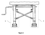
- This invention relates to the jacks ensuring trailers, truck trailers and tractor trailers to stand firmly and functionally in park without a tractor unit.
- Trailer parking legs are used in order to ensure trailers, truck trailers and tractor trailers to stand independently in park without a tractor unit.
- Two parking legs are fixed on the right and left sides of the wheelless front parts of vehicles such as trailer, tractor trailer.
- the fact that the part, which is located in the height adjusting mechanisms of parking legs in the left and right hands and called as nut, has different geometry for both legs is one of the most important problems of parking legs produced today.
- the reason for this problem is the fact that the height adjusting shaft passing through the nut is not produced equiaxially with the body of parking leg.
- the shaft used in the left parking leg of the vehicle is located on the right side of parking leg, and the shaft used in the right parking leg of the vehicle is located on the left side of parking leg.
- a telescopic support device for trailers is mentioned.
- the device includes an outer tube, a first inner tube that can stretch downward inside the outer tube and at least one telescopic support leg consisting of one fixing plate for fixing the support bracket to the object to be supported.
- it is produced with girders from a light metal like aluminum alloy as monolith with the outer tube fixing plate by extrusion method.
- the objective of this invention is to produce a parking leg ensuring vehicles such as trailers, truck trailers and tractor trailers to stand functional and in balance independently of a tractor unit.
- Another objective of this invention is to produce a parking leg which is equiaxial with height adjusting shaft, outer bushing and inner bushing.
- Another object of this invention is to produce a lightened and strengthened parking leg.
- Another object of this invention is to produce a cost-efficient parking leg.
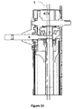
- Parking leg (1) subjecting to the invention which ensures trailers, truck trailers and tractor trailers to stand firmly and functionally in park without a tractor unit includes;
- Inner bushing (2) constitutes the part of the trailer parking leg (1) subjecting to the invention that is fixed on the ground. Other parts of the parking leg (1) are connected to the inner bushing (2) directly or indirectly.
- the inner bushing (2) is produced from a sheet metal made from any metal or metal alloy for the preferred application of the invention.
- stamping press (13) is exerted to the bushing. Usage of heavy and costly shaped tubes is prevented by producing inner bushing from sheet metal.
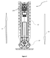
- the outer bushing (3) circles the inner bushing (2) and preferably has a tetragonal structure as the inner bushing (2).
- the outer bushing (3) can move up and down over the inner bushing (2) while the height of the parking leg (1) is adjusted.
- the outer bushing (3) is produced from a sheet metal made from any metal or metal alloy for the preferred application of the invention.
- stamping press (13) is exerted to the bushing.
- the drive shaft (4) is the part to which the necessary drive is given for the height adjustment of the parking leg (1). During the upward and downward movement of the outer bushing (3), the drive shaft (4) also moves together with the outer bushing (3). The drive shaft (4) can move inside or outside of the outer bushing (3).
- the pinion gear (5) is fixed to the drive shaft (4) as equiaxial with the drive shaft (4).
- the pinion gear (5) gets in contact with the big gear ring (6).
- the pinion gear (5) starts to rotate the big gear ring (6) with the drive it gets from the drive shaft (4).
- the pinion gear (5) contacts with the gears on the inner surface of the drive gear (19).
- the trailer parking leg can be used in preferred speed by moving the drive shaft (4) in the direction of arrow C or arrow B.
- the big gear ring (6) When the big gear ring (6) is pushed in the direction of arrow C, it contacts with the pinion gear (5).
- the big gear ring (6) is fixed to the support shaft (8) which passes through its center equiaxially.
- the big gear ring (6) starts to rotate with the drive it gets from the pinion gear (5) and rotates the support shaft (8) in the same axis.
- the vertical cone gear (7) is fixed to the support shaft (8) equiaxially with the support shaft (8).
- the vertical cone gear (7) also starts to rotate in the same axis with the support shaft (8).
- the vertical cone gear (7) is in contact with the horizontal cone gear (9).
- the movement of the vertical cone gear (7) enables the horizontal cone gear (9) which is fixed in the outer bushing in the same axis with inner bushing (2) and outer bushing (3) to rotate around its own axis.
- the vertical cone gear (7) and the horizontal cone gear (9) is located inside the outer bushing (3).
- the horizontal cone gear (9) is fixed to the height adjusting shaft (10) which is placed in the same axis with the horizontal cone gear (9). By the movement of the horizontal cone gear (9), the height adjusting gear starts to rotate in the same axis.
- the screw pitches on the exterior surface of the height adjusting shaft (10) are in cooperation with the screw pitches on the threaded hole (111) located on the nut.
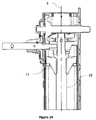
- the pinion gear (5) which is fixed on the drive shaft (4) enables the drive gear (19) to rotate in the same axis and direction.
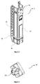
- the drive gear (19) is placed equiaxially with the drive shaft (4) on the part of drive shaft (4) out of the outer bushing (3) and in such a way that it can rotate independently of the drive shaft.
- the drive gear (19) which is placed outside of the outer bushing (3) is preferably covered by transmission cover (18).
- the small gear ring (20) is fixed to the part of support shaft (8) that is removed from the outer bushing (3) through the assembly slot (14).
- the small gear ring (20) is in contact with the drive gear (19) and transfers the drive it gets from the drive gear (19) to the support shaft (8) and the big gear ring (6).
- the small gear ring (20) is covered with the transmission cover for the preferred application of the invention.
- the height adjusting shaft (10) By placing the small gear ring (20) and drive gear (19) outside of the outer bushing (3), a wide area is provided inside the inner bushing (2) and the height adjusting shaft (10) can be placed in the same axis with the inner bushing (2). By this way, the center of threaded hole (111) through which the height adjusting shaft (10) passes comes up to the symmetry axis (S) of the nut (11) and the inner bushing (2).
- the fact that the small gear ring (20) and drive shaft (4) are placed outside of the outer bushing (3) also facilitates the assembly and maintenance of small gear ring (20) and drive shaft (4).
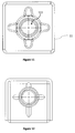
- the connector plate (12) is the part with which the parking leg (1) subjecting to the invention is assembled to vehicles like trailers.
- the connector plate (12) is produced as monolith with the outer bushing (3) for the preferred application of the invention.
- stamping press In order to increase the endurance of outer bushing (3) and inner bushing (2) on the parking leg (1) subjecting to the invention stamping press (13), which can be in different forms, is used to give a shape. By this way, endurance level against deformation has increased; the opportunity of production with lighter materials has arisen, total weight and cost have decreased.
- Profile presses (15) are available under the outer bushing (3) for increasing the endurance level. Bands are not required anymore for this part thanks to the increased endurance level attained by profile pressing (15). By this way the number of the materials decreases, and so do the cost and weight.
- Equiaxial countersinks (16) are placed on the connector plates equiaxially with the screw holes (121). Equiaxial countersinks (16) provide high endurance, a firm structure and easy assembly.
- the assembly slot (14) is a slot opened on the outer bushing (3).
- Small gear ring is placed on the part of support shaft (8) driving off the outer bushing (3), which locates out of the outer bushing (3) through the assembly slot.
- the fact that the small gear ring (20) is placed out of the outer bushing (3) through the assembly slot (14) facilitates maintenance and assembly.
- the drive gear (19) can be placed on the part of the drive shaft (4) out of the outer bushing by the fact that the small gear ring (20) is placed out of the outer bushing (3). By this way, maintenance and assembly of the drive gear (19) can be done easily.
- the transmission cover (18) is placed over the drive gear (19) and small gear ring (20) which locate out of the outer bushing (3), and protect drive gear (19) and small gear ring (20) from outer environment.
- the transmission cover (18) is produced in a way that it can be removed from the outer bushing (3).
- the transmission cover (18) is preferably fixed to the outer bushing with at least one screw. Countersinks are placed equiaxially with the connection axis around the screw holes (which are not shown in figures) used for fixing the transmission cover (18) to the outer bushing (3). By this way, the connection becomes more rigid.
- the endurance level of the transmission cover (18) is increased by applying horizontal, vertical and rotational stamping press.
Claims (14)
- Un pied de stationnement (1) permettant aux remorques, remorques de camion, et remorques de tracteur de reposer fermement et fonctionnellement dans le parking sans ayant une unité de tracteur comportant:- au moins une bague intérieure (2),- au moins une bague extérieure (3) située à l'extérieure de ladite au moins une bague intérieure (2) et se déplaçant vers le haut (U) et vers le bas (D),- au moins un capot de transmission (18) située sur au moins une bague extérieure (3),- au moins un arbre d'entrainement (4) placé verticalement aux axes de ladite au moins une bague intérieure (2) et au moins une bague extérieure (3),- au moins un engrenage à pignons (5) fixé sur au moins un arbre d'entrainement (4) étant équiaxial avec ledit au moins un arbre d'entrainement,- au moins une large couronne dentée (6),- au moins un pignon conique vertical (7) fixé sur au moins une large couronne dentée (6) étant équiaxial avec ladite large couronne dentée (6),- au moins un arbre de support (8) passant par les centres de ladite au moins une couronne dentée (6) et au moins un pignon conique vertical (7),- au moins un pignon conique horizontal (9) placé dans un axe vertical à l'axe dudit pignon conique vertical (7) et étant en contact avec au moins un pignon conique vertical (7),- au moins un arbre de réglage en hauteur (10) fixé sur au moins un pignon conique horizontal (9),- au moins un sabot (17) fixé ladite au moins une bague intérieure (2),- au moins un palier d'arbre d'entrainement (23) situé dans au moins une bague extérieure (3) et supportant au moins arbre d'entrainement (4) et par lequel passe au moins un arbre de réglage en hauteur (10),- au moins un écrou (11) par lequel passe au moins un arbre de réglage en hauteur (10) et qui est placé dans ladite au moins une bague intérieure (2),- un trou taraudé (111) situé sur ladite au moins un écrou (11) assurant que ledit arbre de réglage (10) passe par ledit au moins un écrou (11),- au moins un écrou-porteur (21) fixant ledit au moins un écrou (11) à l'intérieur de ladite au moins une bague intérieure (2),- un carter d'huile (22) situé sur la partie supérieure (U) de l'écrou,- au moins un engrenage d'entrainement (19),- au moins une petite bague d'entrainement (20) transférant la transmission arrivant dudit au moins en engrenage d'entrainement (19) à l'arbre support (8) et la large bague d'entrainement (6), aux plaques de connexion (12) sur les deux côtés de ladite au moins une bague extérieure (3), aux trous de vis (121) situés sur les plaques de connexion (12), la pression d'emboutissage (13) étant appliquée sur ladite au moins une bague extérieure (3) pour augmenter la résistance de ladite au moins une bague extérieure (3),- au moins un rainure de montage (14) placé sur au moins une bague extérieure (3), le profilé pressant (15) exercé à ladite au moins une bague extérieure (3), les fraises équiaxiaux (16) sur les plaques de connexion (12), et dans lequel est placée un arbre de réglage en hauteur (10) à l'intérieur de ladite au moins une bague intérieure (2) équiaxialement avec ladite au moins une bague intérieure (2), un écrou (11) ayant un trou taraudé (111) dont le centre est sur l'axe symétrique dudit au moins un écrou (11),- au moins un rainure de montage (14) assurant le placement dudit au moins un arbre d'entrainement (4) et de ladite au moins une petite bauge d'entrainement (20) sur l'extérieure de ladite bague extérieure (3) en permettant au arbre d'entrainement de support (8) d'actionner ladite au moins une bague extérieure (3),- ladite au moins une petite bague d'entrainement (20) étant placée à l'extérieure de ladite bague extérieure (3) afin de faire de la place dans ladite au moins une bague intérieure (2) et faciliter le maintien et le montage,- ladite au moins un engrenage d'entrainement (19) étant placée à l'extérieure de ladite bague extérieure (3) afin de faire de la place dans ladite au moins une bague intérieure (2) et faciliter le maintien et le montage,- ladite au moins une bague intérieure (2) étant réalisée en tôle métallique pour les poids et les coûts réduits, et dont le niveau de résistance est augmenté par la pression d'emboutissage (13),- ladite au moins une bague extérieure (3) étant réalisée en tôle métallique pour les poids et les coûts réduits, et dont le niveau de résistance est augmenté par la pression d'emboutissage (13).
- Un pied de stationnement (1) comme indiqué dans la revendication 1 qui est caractérisé en une bague extérieure (3) pouvant se déplacer vers le haut et le bas sur ladite au moins une bague intérieure (2).
- Un pied de stationnement (1) comme indiqué dans l'une des revendications précédentes qui est caractérisé par ladite au moins un arbre d'entrainement (4) se déplaçant avec la bague extérieure (3) pendant le mouvement de ladite au moins une bague extérieure (3).
- Un pied de stationnement (1) comme indiqué dans l'une des revendications précédentes qui est caractérisé par au moins un arbre d'entrainement (4), dans lequel l'une de ses extrémités peut actionner ladite au moins une bague extérieure (3) par le rainure de montage (14).
- Un pied de stationnement (1) comme indiqué dans l'une des revendications précédentes qui est caractérisé par l'arbre de support (8), dans lequel l'une de ses extrémités peut actionner ladite au moins une bague extérieure (3) par le rainure de montage (14).
- Un pied de stationnement (1) comme indiqué dans l'une des revendications précédentes qui est caractérisé par ledit arbre de réglage (10) avec les pas de vis sur sa surface extérieure.
- Un pied de stationnement (1) comme indiqué dans l'une des revendications précédentes qui est caractérisé par au moins un écrou (11) avec les pas de vis sur sa surface intérieure.
- Un pied de stationnement (1) comme indiqué dans l'une des revendications précédentes qui est caractérisé par un engrenage d'entrainement (19) qui est fixé à la partie dudit au moins un arbre d'entrainement (4), qui peut être enlevé de ladite au moins une bague extérieure (3) par le rainure de montage (14).
- Un pied de stationnement (1) comme indiqué dans l'une des revendications précédentes qui est caractérisé par une bauge d'entrainement qui est fixé à la partie de l'arbre de support (8) qui peut être enlevé de ladite au moins une bague extérieure (3) par le rainure de montage (14).
- Un pied de stationnement (1) comme indiqué dans l'une des revendications précédentes qui est caractérisé par ledit rainure de montage (14) placé sur ladite au moins une bague extérieure (3) et assurant le placement de l'arbre d'entrainement (19) et ladite au moins une petite bague d'entrainement (20) sur l'extérieure de ladite au moins une bague extérieure (3) en permettant à une extrémité de l'arbre de support (8) et l'arbre d'entrainement (4) d'actionner la bague extérieure (3).
- Un pied de stationnement (1) comme indiqué dans l'une des revendications précédentes qui est caractérisé par un capot de transmission (18) placé sur ledit au moins un engrenage d'entrainement (19) et ladite petite bague d'entrainement (20) située à l'extérieur de ladite au moins une bague extérieure (3) et protégeant ledit au moins engrenage d'entrainement (19) et ladite petite bague d'entrainement (20) du milieu extérieur.
- Un pied de stationnement (1) selon la revendication 11 qui est caractérisé par ledit capot de transmission (18) pouvant être monté à ou démonté de ladite au moins une bague extérieure (3) par les vis.
- Un pied de stationnement (1) selon la revendication 11 ou 12 qui est caractérisé par ledit capot de transmission (18) ayant des fraises étant équiaxiaux avec les axes de connexion, autour des trous de vis utilisés pour son montage à ladite au moins une bague extérieure.
- Un pied de stationnement (1) comme indiqué dans la revendication 11 ou 12 ou 13 qui est caractérisé par le capot de transmission (18) dont le niveau de résistance est augmenté par la pression d'emboutissage horizontale, verticale, et rotative.
Applications Claiming Priority (2)
| Application Number | Priority Date | Filing Date | Title |
|---|---|---|---|
| TR201109286 | 2011-09-21 | ||
| PCT/IB2011/055101 WO2013041917A1 (fr) | 2011-09-21 | 2011-11-15 | Béquille |
Publications (2)
| Publication Number | Publication Date |
|---|---|
| EP2748040A1 EP2748040A1 (fr) | 2014-07-02 |
| EP2748040B1 true EP2748040B1 (fr) | 2016-03-09 |
Family
ID=45390125
Family Applications (1)
| Application Number | Title | Priority Date | Filing Date |
|---|---|---|---|
| EP11799482.2A Active EP2748040B1 (fr) | 2011-09-21 | 2011-11-15 | Train d'atterrissage |
Country Status (2)
| Country | Link |
|---|---|
| EP (1) | EP2748040B1 (fr) |
| WO (1) | WO2013041917A1 (fr) |
Family Cites Families (6)
| Publication number | Priority date | Publication date | Assignee | Title |
|---|---|---|---|---|
| DE3902613A1 (de) * | 1989-01-29 | 1990-08-02 | Jost Werke Gmbh | Teleskop-stuetzvorrichtung |
| DE19836635C5 (de) * | 1998-08-13 | 2005-07-14 | Jost-Werke Gmbh & Co. Kg | Vorrichtung zum Abstützen eines Aufliegers eines Sattelschleppers |
| ES2354496T3 (es) * | 2002-04-02 | 2011-03-15 | Saf-Holland, Inc. | Tren de estacionamiento y método de ensamblaje. |
| DE102006035919A1 (de) * | 2006-07-31 | 2008-02-14 | Haacon Hebetechnik Gmbh | Hubeinrichtung |
| EP2223830A4 (fr) * | 2007-11-21 | 2014-03-12 | Guangdong Fuwa Eng Mfg Co Ltd | Ecrou de sollicitation de support de semi-remorque |
| DE202009006892U1 (de) * | 2009-03-16 | 2009-09-03 | Riedl, Reinhold, Dipl.-Ing. | Höhenverstellbare Stütze für Sattelauflieger o.dgl. |
-
2011
- 2011-11-15 EP EP11799482.2A patent/EP2748040B1/fr active Active
- 2011-11-15 WO PCT/IB2011/055101 patent/WO2013041917A1/fr active Application Filing
Also Published As
| Publication number | Publication date |
|---|---|
| EP2748040A1 (fr) | 2014-07-02 |
| WO2013041917A1 (fr) | 2013-03-28 |
Similar Documents
| Publication | Publication Date | Title |
|---|---|---|
| CN1651291A (zh) | 用于半拖车或者类似物的可调节高度的支架 | |
| DE60106157T2 (de) | Automatische Radmontier- und Demontiervorrichtung und damit ausgestattetes Radmontagegerät | |
| EP2870102B1 (fr) | Dispositif de levage et procédé de montage et de démontage d'une roue au moyen d'un tel dispositif de levage | |
| CN102272483A (zh) | 包含湿式制动器的传动装置 | |
| CN103153752A (zh) | 转向装置 | |
| EP2611625B1 (fr) | Ensemble roue pour vehicules | |
| EP1714858A1 (fr) | Entraînement auxiliaire pour remorque avec rouleau d'entraînement supporté d'un seul côté | |
| DE3145655C1 (de) | Schuesselmuehlengetriebe | |
| DE202014101670U1 (de) | Schnecken-Rad-Hilfskraftlenkgetriebe | |
| CA2897213A1 (fr) | Cric d'enroulement dual | |
| DE3900075A1 (de) | Radkopf fuer fahrzeuge | |
| EP2748040B1 (fr) | Train d'atterrissage | |
| CN113680911A (zh) | 一种新型铝材加工用冲压装置 | |
| EP3504102A1 (fr) | Volant de direction pour actionner un mouvement de braquage d'un véhicule | |
| CN110667309A (zh) | 一种汽车轮胎自动装配和装卸装置 | |
| CN217474568U (zh) | 一种用于铝型材的冲压结构 | |
| EP1857346A3 (fr) | Appareil de direction de type bascule doté d'un engrenage radial fixe | |
| CN101092148A (zh) | 汽车转向管柱可调倾角装置 | |
| CN113581576B (zh) | 一种用于医药复合硬片包装的喷码设备 | |
| EP1785323B1 (fr) | Supports ajustables en hauteur pour semi-remorques ou similaires | |
| CN110542368A (zh) | 一种重卡汽车精密零件销柱表面的检查装置 | |
| KR101056810B1 (ko) | 차량의 액슬캐리어 | |
| US7367546B1 (en) | Tire jack | |
| RU2220090C1 (ru) | Домкрат для автомобиля | |
| DE3921686C2 (de) | Stützvorrichtung für Sattelanhänger |
Legal Events
| Date | Code | Title | Description |
|---|---|---|---|
| PUAI | Public reference made under article 153(3) epc to a published international application that has entered the european phase |
Free format text: ORIGINAL CODE: 0009012 |
|
| 17P | Request for examination filed |
Effective date: 20140321 |
|
| AK | Designated contracting states |
Kind code of ref document: A1 Designated state(s): AL AT BE BG CH CY CZ DE DK EE ES FI FR GB GR HR HU IE IS IT LI LT LU LV MC MK MT NL NO PL PT RO RS SE SI SK SM TR |
|
| DAX | Request for extension of the european patent (deleted) | ||
| 17Q | First examination report despatched |
Effective date: 20150217 |
|
| GRAP | Despatch of communication of intention to grant a patent |
Free format text: ORIGINAL CODE: EPIDOSNIGR1 |
|
| INTG | Intention to grant announced |
Effective date: 20151016 |
|
| GRAS | Grant fee paid |
Free format text: ORIGINAL CODE: EPIDOSNIGR3 |
|
| GRAA | (expected) grant |
Free format text: ORIGINAL CODE: 0009210 |
|
| AK | Designated contracting states |
Kind code of ref document: B1 Designated state(s): AL AT BE BG CH CY CZ DE DK EE ES FI FR GB GR HR HU IE IS IT LI LT LU LV MC MK MT NL NO PL PT RO RS SE SI SK SM TR |
|
| REG | Reference to a national code |
Ref country code: GB Ref legal event code: FG4D |
|
| REG | Reference to a national code |
Ref country code: AT Ref legal event code: REF Ref document number: 779235 Country of ref document: AT Kind code of ref document: T Effective date: 20160315 Ref country code: CH Ref legal event code: EP |
|
| REG | Reference to a national code |
Ref country code: IE Ref legal event code: FG4D |
|
| REG | Reference to a national code |
Ref country code: DE Ref legal event code: R096 Ref document number: 602011023882 Country of ref document: DE |
|
| REG | Reference to a national code |
Ref country code: LT Ref legal event code: MG4D |
|
| REG | Reference to a national code |
Ref country code: NL Ref legal event code: MP Effective date: 20160309 |
|
| PG25 | Lapsed in a contracting state [announced via postgrant information from national office to epo] |
Ref country code: FI Free format text: LAPSE BECAUSE OF FAILURE TO SUBMIT A TRANSLATION OF THE DESCRIPTION OR TO PAY THE FEE WITHIN THE PRESCRIBED TIME-LIMIT Effective date: 20160309 Ref country code: GR Free format text: LAPSE BECAUSE OF FAILURE TO SUBMIT A TRANSLATION OF THE DESCRIPTION OR TO PAY THE FEE WITHIN THE PRESCRIBED TIME-LIMIT Effective date: 20160610 Ref country code: ES Free format text: LAPSE BECAUSE OF FAILURE TO SUBMIT A TRANSLATION OF THE DESCRIPTION OR TO PAY THE FEE WITHIN THE PRESCRIBED TIME-LIMIT Effective date: 20160309 Ref country code: HR Free format text: LAPSE BECAUSE OF FAILURE TO SUBMIT A TRANSLATION OF THE DESCRIPTION OR TO PAY THE FEE WITHIN THE PRESCRIBED TIME-LIMIT Effective date: 20160309 Ref country code: NO Free format text: LAPSE BECAUSE OF FAILURE TO SUBMIT A TRANSLATION OF THE DESCRIPTION OR TO PAY THE FEE WITHIN THE PRESCRIBED TIME-LIMIT Effective date: 20160609 |
|
| REG | Reference to a national code |
Ref country code: AT Ref legal event code: MK05 Ref document number: 779235 Country of ref document: AT Kind code of ref document: T Effective date: 20160309 |
|
| PG25 | Lapsed in a contracting state [announced via postgrant information from national office to epo] |
Ref country code: SE Free format text: LAPSE BECAUSE OF FAILURE TO SUBMIT A TRANSLATION OF THE DESCRIPTION OR TO PAY THE FEE WITHIN THE PRESCRIBED TIME-LIMIT Effective date: 20160309 Ref country code: LT Free format text: LAPSE BECAUSE OF FAILURE TO SUBMIT A TRANSLATION OF THE DESCRIPTION OR TO PAY THE FEE WITHIN THE PRESCRIBED TIME-LIMIT Effective date: 20160309 Ref country code: PL Free format text: LAPSE BECAUSE OF FAILURE TO SUBMIT A TRANSLATION OF THE DESCRIPTION OR TO PAY THE FEE WITHIN THE PRESCRIBED TIME-LIMIT Effective date: 20160309 Ref country code: RS Free format text: LAPSE BECAUSE OF FAILURE TO SUBMIT A TRANSLATION OF THE DESCRIPTION OR TO PAY THE FEE WITHIN THE PRESCRIBED TIME-LIMIT Effective date: 20160309 Ref country code: LV Free format text: LAPSE BECAUSE OF FAILURE TO SUBMIT A TRANSLATION OF THE DESCRIPTION OR TO PAY THE FEE WITHIN THE PRESCRIBED TIME-LIMIT Effective date: 20160309 Ref country code: NL Free format text: LAPSE BECAUSE OF FAILURE TO SUBMIT A TRANSLATION OF THE DESCRIPTION OR TO PAY THE FEE WITHIN THE PRESCRIBED TIME-LIMIT Effective date: 20160309 |
|
| PG25 | Lapsed in a contracting state [announced via postgrant information from national office to epo] |
Ref country code: IS Free format text: LAPSE BECAUSE OF FAILURE TO SUBMIT A TRANSLATION OF THE DESCRIPTION OR TO PAY THE FEE WITHIN THE PRESCRIBED TIME-LIMIT Effective date: 20160709 Ref country code: EE Free format text: LAPSE BECAUSE OF FAILURE TO SUBMIT A TRANSLATION OF THE DESCRIPTION OR TO PAY THE FEE WITHIN THE PRESCRIBED TIME-LIMIT Effective date: 20160309 |
|
| PG25 | Lapsed in a contracting state [announced via postgrant information from national office to epo] |
Ref country code: SK Free format text: LAPSE BECAUSE OF FAILURE TO SUBMIT A TRANSLATION OF THE DESCRIPTION OR TO PAY THE FEE WITHIN THE PRESCRIBED TIME-LIMIT Effective date: 20160309 Ref country code: RO Free format text: LAPSE BECAUSE OF FAILURE TO SUBMIT A TRANSLATION OF THE DESCRIPTION OR TO PAY THE FEE WITHIN THE PRESCRIBED TIME-LIMIT Effective date: 20160309 Ref country code: SM Free format text: LAPSE BECAUSE OF FAILURE TO SUBMIT A TRANSLATION OF THE DESCRIPTION OR TO PAY THE FEE WITHIN THE PRESCRIBED TIME-LIMIT Effective date: 20160309 Ref country code: PT Free format text: LAPSE BECAUSE OF FAILURE TO SUBMIT A TRANSLATION OF THE DESCRIPTION OR TO PAY THE FEE WITHIN THE PRESCRIBED TIME-LIMIT Effective date: 20160711 Ref country code: CZ Free format text: LAPSE BECAUSE OF FAILURE TO SUBMIT A TRANSLATION OF THE DESCRIPTION OR TO PAY THE FEE WITHIN THE PRESCRIBED TIME-LIMIT Effective date: 20160309 Ref country code: AT Free format text: LAPSE BECAUSE OF FAILURE TO SUBMIT A TRANSLATION OF THE DESCRIPTION OR TO PAY THE FEE WITHIN THE PRESCRIBED TIME-LIMIT Effective date: 20160309 |
|
| REG | Reference to a national code |
Ref country code: DE Ref legal event code: R097 Ref document number: 602011023882 Country of ref document: DE |
|
| PG25 | Lapsed in a contracting state [announced via postgrant information from national office to epo] |
Ref country code: IT Free format text: LAPSE BECAUSE OF FAILURE TO SUBMIT A TRANSLATION OF THE DESCRIPTION OR TO PAY THE FEE WITHIN THE PRESCRIBED TIME-LIMIT Effective date: 20160309 Ref country code: BE Free format text: LAPSE BECAUSE OF FAILURE TO SUBMIT A TRANSLATION OF THE DESCRIPTION OR TO PAY THE FEE WITHIN THE PRESCRIBED TIME-LIMIT Effective date: 20160309 |
|
| PLBE | No opposition filed within time limit |
Free format text: ORIGINAL CODE: 0009261 |
|
| STAA | Information on the status of an ep patent application or granted ep patent |
Free format text: STATUS: NO OPPOSITION FILED WITHIN TIME LIMIT |
|
| PG25 | Lapsed in a contracting state [announced via postgrant information from national office to epo] |
Ref country code: DK Free format text: LAPSE BECAUSE OF FAILURE TO SUBMIT A TRANSLATION OF THE DESCRIPTION OR TO PAY THE FEE WITHIN THE PRESCRIBED TIME-LIMIT Effective date: 20160309 |
|
| 26N | No opposition filed |
Effective date: 20161212 |
|
| PG25 | Lapsed in a contracting state [announced via postgrant information from national office to epo] |
Ref country code: BG Free format text: LAPSE BECAUSE OF FAILURE TO SUBMIT A TRANSLATION OF THE DESCRIPTION OR TO PAY THE FEE WITHIN THE PRESCRIBED TIME-LIMIT Effective date: 20160609 |
|
| PG25 | Lapsed in a contracting state [announced via postgrant information from national office to epo] |
Ref country code: SI Free format text: LAPSE BECAUSE OF FAILURE TO SUBMIT A TRANSLATION OF THE DESCRIPTION OR TO PAY THE FEE WITHIN THE PRESCRIBED TIME-LIMIT Effective date: 20160309 |
|
| REG | Reference to a national code |
Ref country code: CH Ref legal event code: PL |
|
| GBPC | Gb: european patent ceased through non-payment of renewal fee |
Effective date: 20161115 |
|
| PG25 | Lapsed in a contracting state [announced via postgrant information from national office to epo] |
Ref country code: LI Free format text: LAPSE BECAUSE OF NON-PAYMENT OF DUE FEES Effective date: 20161130 Ref country code: CH Free format text: LAPSE BECAUSE OF NON-PAYMENT OF DUE FEES Effective date: 20161130 |
|
| REG | Reference to a national code |
Ref country code: IE Ref legal event code: MM4A |
|
| REG | Reference to a national code |
Ref country code: FR Ref legal event code: ST Effective date: 20170731 |
|
| PG25 | Lapsed in a contracting state [announced via postgrant information from national office to epo] |
Ref country code: LU Free format text: LAPSE BECAUSE OF NON-PAYMENT OF DUE FEES Effective date: 20161130 |
|
| PG25 | Lapsed in a contracting state [announced via postgrant information from national office to epo] |
Ref country code: FR Free format text: LAPSE BECAUSE OF NON-PAYMENT OF DUE FEES Effective date: 20161130 |
|
| PG25 | Lapsed in a contracting state [announced via postgrant information from national office to epo] |
Ref country code: GB Free format text: LAPSE BECAUSE OF NON-PAYMENT OF DUE FEES Effective date: 20161115 Ref country code: IE Free format text: LAPSE BECAUSE OF NON-PAYMENT OF DUE FEES Effective date: 20161115 |
|
| PG25 | Lapsed in a contracting state [announced via postgrant information from national office to epo] |
Ref country code: HU Free format text: LAPSE BECAUSE OF FAILURE TO SUBMIT A TRANSLATION OF THE DESCRIPTION OR TO PAY THE FEE WITHIN THE PRESCRIBED TIME-LIMIT; INVALID AB INITIO Effective date: 20111115 |
|
| PG25 | Lapsed in a contracting state [announced via postgrant information from national office to epo] |
Ref country code: MC Free format text: LAPSE BECAUSE OF FAILURE TO SUBMIT A TRANSLATION OF THE DESCRIPTION OR TO PAY THE FEE WITHIN THE PRESCRIBED TIME-LIMIT Effective date: 20160309 Ref country code: MK Free format text: LAPSE BECAUSE OF FAILURE TO SUBMIT A TRANSLATION OF THE DESCRIPTION OR TO PAY THE FEE WITHIN THE PRESCRIBED TIME-LIMIT Effective date: 20160309 Ref country code: CY Free format text: LAPSE BECAUSE OF FAILURE TO SUBMIT A TRANSLATION OF THE DESCRIPTION OR TO PAY THE FEE WITHIN THE PRESCRIBED TIME-LIMIT Effective date: 20160309 |
|
| PG25 | Lapsed in a contracting state [announced via postgrant information from national office to epo] |
Ref country code: MT Free format text: LAPSE BECAUSE OF NON-PAYMENT OF DUE FEES Effective date: 20161115 |
|
| PG25 | Lapsed in a contracting state [announced via postgrant information from national office to epo] |
Ref country code: TR Free format text: LAPSE BECAUSE OF FAILURE TO SUBMIT A TRANSLATION OF THE DESCRIPTION OR TO PAY THE FEE WITHIN THE PRESCRIBED TIME-LIMIT Effective date: 20160309 Ref country code: AL Free format text: LAPSE BECAUSE OF FAILURE TO SUBMIT A TRANSLATION OF THE DESCRIPTION OR TO PAY THE FEE WITHIN THE PRESCRIBED TIME-LIMIT Effective date: 20160309 |
|
| PGFP | Annual fee paid to national office [announced via postgrant information from national office to epo] |
Ref country code: DE Payment date: 20231130 Year of fee payment: 13 |